EP1812758B1 - Method and device for supplying hot water - Google Patents
Method and device for supplying hot water Download PDFInfo
- Publication number
- EP1812758B1 EP1812758B1 EP05817451.7A EP05817451A EP1812758B1 EP 1812758 B1 EP1812758 B1 EP 1812758B1 EP 05817451 A EP05817451 A EP 05817451A EP 1812758 B1 EP1812758 B1 EP 1812758B1
- Authority
- EP
- European Patent Office
- Prior art keywords
- liquid
- heating
- pump
- temperature
- heating element
- Prior art date
- Legal status (The legal status is an assumption and is not a legal conclusion. Google has not performed a legal analysis and makes no representation as to the accuracy of the status listed.)
- Active
Links
- XLYOFNOQVPJJNP-UHFFFAOYSA-N water Substances O XLYOFNOQVPJJNP-UHFFFAOYSA-N 0.000 title claims description 41
- 238000000034 method Methods 0.000 title claims description 35
- 238000010438 heat treatment Methods 0.000 claims description 141
- 239000007788 liquid Substances 0.000 claims description 108
- 229910052782 aluminium Inorganic materials 0.000 claims description 8
- XAGFODPZIPBFFR-UHFFFAOYSA-N aluminium Chemical compound [Al] XAGFODPZIPBFFR-UHFFFAOYSA-N 0.000 claims description 8
- 239000012530 fluid Substances 0.000 claims description 5
- 230000001960 triggered effect Effects 0.000 claims description 4
- 239000004411 aluminium Substances 0.000 claims 1
- 239000007769 metal material Substances 0.000 claims 1
- 230000000295 complement effect Effects 0.000 description 27
- 239000000463 material Substances 0.000 description 9
- 235000013353 coffee beverage Nutrition 0.000 description 7
- 229910001220 stainless steel Inorganic materials 0.000 description 5
- 239000010935 stainless steel Substances 0.000 description 5
- 238000009835 boiling Methods 0.000 description 3
- 230000007423 decrease Effects 0.000 description 3
- 239000004033 plastic Substances 0.000 description 3
- 238000002360 preparation method Methods 0.000 description 3
- 235000013361 beverage Nutrition 0.000 description 2
- 230000033228 biological regulation Effects 0.000 description 2
- 238000009826 distribution Methods 0.000 description 2
- 238000005265 energy consumption Methods 0.000 description 2
- 239000011521 glass Substances 0.000 description 2
- 230000005484 gravity Effects 0.000 description 2
- 235000012171 hot beverage Nutrition 0.000 description 2
- 239000011810 insulating material Substances 0.000 description 2
- 238000004519 manufacturing process Methods 0.000 description 2
- 238000005259 measurement Methods 0.000 description 2
- RYGMFSIKBFXOCR-UHFFFAOYSA-N Copper Chemical compound [Cu] RYGMFSIKBFXOCR-UHFFFAOYSA-N 0.000 description 1
- 229930182556 Polyacetal Natural products 0.000 description 1
- 239000004952 Polyamide Substances 0.000 description 1
- 239000004642 Polyimide Substances 0.000 description 1
- 229920000491 Polyphenylsulfone Polymers 0.000 description 1
- 239000004743 Polypropylene Substances 0.000 description 1
- 241001122767 Theaceae Species 0.000 description 1
- 230000015572 biosynthetic process Effects 0.000 description 1
- 238000010411 cooking Methods 0.000 description 1
- 229910052802 copper Inorganic materials 0.000 description 1
- 239000010949 copper Substances 0.000 description 1
- 238000005260 corrosion Methods 0.000 description 1
- 230000007797 corrosion Effects 0.000 description 1
- 238000005520 cutting process Methods 0.000 description 1
- 230000008021 deposition Effects 0.000 description 1
- 238000001514 detection method Methods 0.000 description 1
- 238000010586 diagram Methods 0.000 description 1
- 230000035622 drinking Effects 0.000 description 1
- 239000003651 drinking water Substances 0.000 description 1
- 235000020188 drinking water Nutrition 0.000 description 1
- 235000015114 espresso Nutrition 0.000 description 1
- 235000013305 food Nutrition 0.000 description 1
- 239000012212 insulator Substances 0.000 description 1
- 238000007726 management method Methods 0.000 description 1
- 239000002245 particle Substances 0.000 description 1
- 229920002647 polyamide Polymers 0.000 description 1
- 239000004417 polycarbonate Substances 0.000 description 1
- 229920000515 polycarbonate Polymers 0.000 description 1
- 229920001721 polyimide Polymers 0.000 description 1
- 229920006324 polyoxymethylene Polymers 0.000 description 1
- -1 polypropylene Polymers 0.000 description 1
- 229920001155 polypropylene Polymers 0.000 description 1
- 230000002035 prolonged effect Effects 0.000 description 1
- 238000007650 screen-printing Methods 0.000 description 1
- 238000007789 sealing Methods 0.000 description 1
- 238000003860 storage Methods 0.000 description 1
- 238000009834 vaporization Methods 0.000 description 1
- 230000008016 vaporization Effects 0.000 description 1
- 239000002699 waste material Substances 0.000 description 1
- 238000004804 winding Methods 0.000 description 1
Images


Classifications
-
- F—MECHANICAL ENGINEERING; LIGHTING; HEATING; WEAPONS; BLASTING
- F24—HEATING; RANGES; VENTILATING
- F24H—FLUID HEATERS, e.g. WATER OR AIR HEATERS, HAVING HEAT-GENERATING MEANS, e.g. HEAT PUMPS, IN GENERAL
- F24H9/00—Details
- F24H9/20—Arrangement or mounting of control or safety devices
-
- F—MECHANICAL ENGINEERING; LIGHTING; HEATING; WEAPONS; BLASTING
- F24—HEATING; RANGES; VENTILATING
- F24H—FLUID HEATERS, e.g. WATER OR AIR HEATERS, HAVING HEAT-GENERATING MEANS, e.g. HEAT PUMPS, IN GENERAL
- F24H1/00—Water heaters, e.g. boilers, continuous-flow heaters or water-storage heaters
- F24H1/10—Continuous-flow heaters, i.e. heaters in which heat is generated only while the water is flowing, e.g. with direct contact of the water with the heating medium
- F24H1/12—Continuous-flow heaters, i.e. heaters in which heat is generated only while the water is flowing, e.g. with direct contact of the water with the heating medium in which the water is kept separate from the heating medium
- F24H1/14—Continuous-flow heaters, i.e. heaters in which heat is generated only while the water is flowing, e.g. with direct contact of the water with the heating medium in which the water is kept separate from the heating medium by tubes, e.g. bent in serpentine form
- F24H1/16—Continuous-flow heaters, i.e. heaters in which heat is generated only while the water is flowing, e.g. with direct contact of the water with the heating medium in which the water is kept separate from the heating medium by tubes, e.g. bent in serpentine form helically or spirally coiled
- F24H1/162—Continuous-flow heaters, i.e. heaters in which heat is generated only while the water is flowing, e.g. with direct contact of the water with the heating medium in which the water is kept separate from the heating medium by tubes, e.g. bent in serpentine form helically or spirally coiled using electrical energy supply
-
- A—HUMAN NECESSITIES
- A47—FURNITURE; DOMESTIC ARTICLES OR APPLIANCES; COFFEE MILLS; SPICE MILLS; SUCTION CLEANERS IN GENERAL
- A47J—KITCHEN EQUIPMENT; COFFEE MILLS; SPICE MILLS; APPARATUS FOR MAKING BEVERAGES
- A47J31/00—Apparatus for making beverages
- A47J31/44—Parts or details or accessories of beverage-making apparatus
- A47J31/54—Water boiling vessels in beverage making machines
-
- F—MECHANICAL ENGINEERING; LIGHTING; HEATING; WEAPONS; BLASTING
- F24—HEATING; RANGES; VENTILATING
- F24H—FLUID HEATERS, e.g. WATER OR AIR HEATERS, HAVING HEAT-GENERATING MEANS, e.g. HEAT PUMPS, IN GENERAL
- F24H1/00—Water heaters, e.g. boilers, continuous-flow heaters or water-storage heaters
- F24H1/10—Continuous-flow heaters, i.e. heaters in which heat is generated only while the water is flowing, e.g. with direct contact of the water with the heating medium
- F24H1/12—Continuous-flow heaters, i.e. heaters in which heat is generated only while the water is flowing, e.g. with direct contact of the water with the heating medium in which the water is kept separate from the heating medium
- F24H1/14—Continuous-flow heaters, i.e. heaters in which heat is generated only while the water is flowing, e.g. with direct contact of the water with the heating medium in which the water is kept separate from the heating medium by tubes, e.g. bent in serpentine form
- F24H1/16—Continuous-flow heaters, i.e. heaters in which heat is generated only while the water is flowing, e.g. with direct contact of the water with the heating medium in which the water is kept separate from the heating medium by tubes, e.g. bent in serpentine form helically or spirally coiled
-
- F—MECHANICAL ENGINEERING; LIGHTING; HEATING; WEAPONS; BLASTING
- F24—HEATING; RANGES; VENTILATING
- F24H—FLUID HEATERS, e.g. WATER OR AIR HEATERS, HAVING HEAT-GENERATING MEANS, e.g. HEAT PUMPS, IN GENERAL
- F24H15/00—Control of fluid heaters
- F24H15/10—Control of fluid heaters characterised by the purpose of the control
- F24H15/174—Supplying heated water with desired temperature or desired range of temperature
-
- F—MECHANICAL ENGINEERING; LIGHTING; HEATING; WEAPONS; BLASTING
- F24—HEATING; RANGES; VENTILATING
- F24H—FLUID HEATERS, e.g. WATER OR AIR HEATERS, HAVING HEAT-GENERATING MEANS, e.g. HEAT PUMPS, IN GENERAL
- F24H15/00—Control of fluid heaters
- F24H15/20—Control of fluid heaters characterised by control inputs
- F24H15/212—Temperature of the water
- F24H15/219—Temperature of the water after heating
-
- F—MECHANICAL ENGINEERING; LIGHTING; HEATING; WEAPONS; BLASTING
- F24—HEATING; RANGES; VENTILATING
- F24H—FLUID HEATERS, e.g. WATER OR AIR HEATERS, HAVING HEAT-GENERATING MEANS, e.g. HEAT PUMPS, IN GENERAL
- F24H15/00—Control of fluid heaters
- F24H15/20—Control of fluid heaters characterised by control inputs
- F24H15/25—Temperature of the heat-generating means in the heater
-
- F—MECHANICAL ENGINEERING; LIGHTING; HEATING; WEAPONS; BLASTING
- F24—HEATING; RANGES; VENTILATING
- F24H—FLUID HEATERS, e.g. WATER OR AIR HEATERS, HAVING HEAT-GENERATING MEANS, e.g. HEAT PUMPS, IN GENERAL
- F24H15/00—Control of fluid heaters
- F24H15/30—Control of fluid heaters characterised by control outputs; characterised by the components to be controlled
- F24H15/335—Control of pumps, e.g. on-off control
-
- F—MECHANICAL ENGINEERING; LIGHTING; HEATING; WEAPONS; BLASTING
- F24—HEATING; RANGES; VENTILATING
- F24H—FLUID HEATERS, e.g. WATER OR AIR HEATERS, HAVING HEAT-GENERATING MEANS, e.g. HEAT PUMPS, IN GENERAL
- F24H15/00—Control of fluid heaters
- F24H15/30—Control of fluid heaters characterised by control outputs; characterised by the components to be controlled
- F24H15/355—Control of heat-generating means in heaters
- F24H15/37—Control of heat-generating means in heaters of electric heaters
-
- F—MECHANICAL ENGINEERING; LIGHTING; HEATING; WEAPONS; BLASTING
- F24—HEATING; RANGES; VENTILATING
- F24H—FLUID HEATERS, e.g. WATER OR AIR HEATERS, HAVING HEAT-GENERATING MEANS, e.g. HEAT PUMPS, IN GENERAL
- F24H15/00—Control of fluid heaters
- F24H15/40—Control of fluid heaters characterised by the type of controllers
- F24H15/414—Control of fluid heaters characterised by the type of controllers using electronic processing, e.g. computer-based
-
- F—MECHANICAL ENGINEERING; LIGHTING; HEATING; WEAPONS; BLASTING
- F24—HEATING; RANGES; VENTILATING
- F24H—FLUID HEATERS, e.g. WATER OR AIR HEATERS, HAVING HEAT-GENERATING MEANS, e.g. HEAT PUMPS, IN GENERAL
- F24H15/00—Control of fluid heaters
- F24H15/40—Control of fluid heaters characterised by the type of controllers
- F24H15/486—Control of fluid heaters characterised by the type of controllers using timers
-
- F—MECHANICAL ENGINEERING; LIGHTING; HEATING; WEAPONS; BLASTING
- F24—HEATING; RANGES; VENTILATING
- F24H—FLUID HEATERS, e.g. WATER OR AIR HEATERS, HAVING HEAT-GENERATING MEANS, e.g. HEAT PUMPS, IN GENERAL
- F24H9/00—Details
- F24H9/20—Arrangement or mounting of control or safety devices
- F24H9/2007—Arrangement or mounting of control or safety devices for water heaters
- F24H9/2014—Arrangement or mounting of control or safety devices for water heaters using electrical energy supply
- F24H9/2028—Continuous-flow heaters
-
- A—HUMAN NECESSITIES
- A47—FURNITURE; DOMESTIC ARTICLES OR APPLIANCES; COFFEE MILLS; SPICE MILLS; SUCTION CLEANERS IN GENERAL
- A47J—KITCHEN EQUIPMENT; COFFEE MILLS; SPICE MILLS; APPARATUS FOR MAKING BEVERAGES
- A47J31/00—Apparatus for making beverages
- A47J31/44—Parts or details or accessories of beverage-making apparatus
- A47J31/54—Water boiling vessels in beverage making machines
- A47J31/542—Continuous-flow heaters
- A47J31/545—Control or safety devices
-
- F—MECHANICAL ENGINEERING; LIGHTING; HEATING; WEAPONS; BLASTING
- F24—HEATING; RANGES; VENTILATING
- F24H—FLUID HEATERS, e.g. WATER OR AIR HEATERS, HAVING HEAT-GENERATING MEANS, e.g. HEAT PUMPS, IN GENERAL
- F24H15/00—Control of fluid heaters
- F24H15/10—Control of fluid heaters characterised by the purpose of the control
- F24H15/156—Reducing the quantity of energy consumed; Increasing efficiency
Landscapes
- Engineering & Computer Science (AREA)
- General Engineering & Computer Science (AREA)
- Chemical & Material Sciences (AREA)
- Thermal Sciences (AREA)
- Combustion & Propulsion (AREA)
- Mechanical Engineering (AREA)
- Physics & Mathematics (AREA)
- Computer Hardware Design (AREA)
- Food Science & Technology (AREA)
- Cookers (AREA)
- Instantaneous Water Boilers, Portable Hot-Water Supply Apparatuses, And Control Of Portable Hot-Water Supply Apparatuses (AREA)
- Control Of Resistance Heating (AREA)
- Devices For Dispensing Beverages (AREA)
Description
La présente invention concerne, de façon générale, un procédé et un dispositif de fourniture d'eau chaude de boisson.The present invention relates generally to a method and a device for supplying hot drinking water.
On connaît des appareils permettant d'obtenir de l'eau très chaude en petite quantité (par opposition aux chauffe-eaux qui fournissent de grande quantité d'eau moyennement chaude) soit de un à deux litres maximum tels que les distributeurs de boissons chaudes, machines à café ou bouilloires.
Il est par exemple connu du document brevet
- un circuit de transport de liquide ;
- une unité de commande électronique dotée d'une source d'alimentation électrique et d'un moyen de commande du dispositif ;
- un élément de chauffe du liquide comportant une résistance chauffante et disposé en série avec une pompe adaptée pour assurer la circulation de liquide dans le circuit à un débit donné, la pompe et l'élément de chauffe étant alimentés électriquement et commandés indépendamment l'un de l'autre par l'unité de commande.
It is for example known from the
- a liquid transport circuit;
- an electronic control unit having a power source and a control means of the device;
- a liquid heating element comprising a heating resistor and arranged in series with a pump adapted to ensure the circulation of liquid in the circuit at a given flow rate, the pump and the heating element being electrically powered and controlled independently one of the other by the control unit.
Ce dispositif de l'art antérieur comporte un réservoir de stockage de liquide chauffé en permanence par l'élément de chauffe à une température comprise entre 50 et 60°C. Dès que l'utilisateur commande une quantité d'eau chaude, l'élément chauffant est alors suralimenté électriquement pour réchauffer l'eau déjà préchauffée par l'appareil jusqu'à une température supérieure pouvant aller jusqu'à ébullition puis, la pompe est actionnée pour délivrer l'eau une température supérieure à 60°.This device of the prior art comprises a liquid storage tank permanently heated by the heating element at a temperature of between 50 and 60 ° C. As soon as the user orders a quantity of hot water, the heating element is then electrically supercharged to heat the water already preheated by the apparatus to a higher temperature up to boiling and then the pump is actuated to deliver the water a temperature greater than 60 °.
Un tel dispositif permet de délivrer rapidement de l'eau chaude mais à pour inconvénient de consommer en permanence de l'énergie nécessaire à la préchauffe.Such a device makes it possible to quickly deliver hot water but for the inconvenience of consuming permanently the energy necessary for preheating.
Dans le cas des bouilloires, l'inconvénient principal est le temps durant lequel l'appareil chauffe l'eau, donnant à l'utilisateur l'impression d'inactivité de l'appareil. Un autre inconvénient est que l'utilisateur à tendance à faire chauffer plus d'eau que nécessaire, ce qui engendre une perte de temps et d'énergie.In the case of kettles, the main disadvantage is the time during which the appliance heats the water, giving the user the impression of inactivity of the appliance. Another disadvantage is that the user tends to heat more water than necessary, which causes a waste of time and energy.
Dans le cas des distributeurs de boissons chaudes ou des machines à café de type « expressos », une quantité d'eau ou une masse d'aluminium est maintenue continuellement en chauffe. Ce qui engendre une consommation d'énergie inutile.In the case of hot beverage dispensers or "espresso" type coffee machines, a quantity of water or a mass of aluminum is kept continuously heated. Which generates unnecessary energy consumption.
De plus, le temps d'attente avant le début de la délivrance de liquide chaud est relativement important et généralement supérieur à 5 secondes, allongeant ainsi le temps pour obtenir la boisson.In addition, the waiting time before the start of the delivery of hot liquid is relatively large and generally greater than 5 seconds, thus extending the time to obtain the drink.
Une machine à café du type précédemment énoncé, mais supprimant la nécessité de préchauffer une grande quantité d'eau est par ailleurs décrite dans le document brevet
Le terme préchauffe désigne toute opération de chauffe antérieure au moment d'actionnement de l'appareil par l'utilisateur et une très forte puissance est à considérer comme supérieure à 3,5 kW sans pour autant aller au-delà, ce qui poserait des difficultés de réseau électrique domestique normalement prévu pour les utilisations dans le domaine du petit électroménager.The term preheating refers to any previous heating operation at the moment of actuation of the device by the user and a very high power is to be considered greater than 3.5 kW without going beyond, which would pose difficulties domestic electrical network normally intended for use in the field of small household appliances.
Par délivrer assez rapidement, il est entendu d'une part commencer à délivrer le liquide chauffé au débit voulu dans un temps au moins inférieur à 5 secondes après une action de commande du dispositif par l'utilisateur, et d'autre part délivrer un volume de liquide d'au moins 12 centilitres à 70°c en moins de 25 secondes.By delivering rather quickly, it is understood firstly to start delivering the heated liquid at the desired rate in a time at least less than 5 seconds after a user control action of the device, and secondly to deliver a volume of liquid of at least 12 centilitres at 70 ° C in less than 25 seconds.
Il est à noter que dans toute la description de l'invention l'abréviation « cl » désigne l'unité centilitre qui correspond à 10-2 décimètres cubes (dix puissance moins deux décimètres cubes). A cette fin, le problème posé est résolu par un procédé selon la revendication 1. Grâce à ce procédé, il est donc possible de satisfaire le problème posé en délivrant rapidement une quantité donné de liquide chaud à plus 70°C sans avoir à faire appel à une préchauffe continue du liquide à délivrer.It should be noted that throughout the description of the invention the abbreviation "cl" designates the unit centilitre which corresponds to 10 -2 cubic decimetres (ten power minus two cubic decimetres). For this purpose, the problem is solved by a method according to
Grâce au ratio ci-dessus, le procédé de chauffe de l'invention peut être mis en oeuvre en alimentant le dispositif par une alimentation secteur disponible sur les réseaux publics domestiques dans le monde (par exemple réseau européen en 220 V à 16 Ampères et en réseau américain en 110 V).Thanks to the above ratio, the heating method of the invention can be implemented by supplying the device with a mains supply available on the public domestic networks in the world (for example European network in 220 V to 16 amps and in US 110V network).
Ainsi la puissance électrique moyenne de la résistance chauffante utilisée pour la mise en oeuvre du procédé et du dispositif de l'invention est choisie pour être inférieure à 3500 W cette valeur pouvant être mesurée lorsque la résistance est alimentée électriquement par un réseau public domestique précédemment évoqué.Thus, the average electrical power of the heating resistor used for the implementation of the method and the device of the invention is chosen to be less than 3500 W, this value being measurable when the resistor is electrically powered by a previously mentioned public home network. .
Suivant l'invention, on commande la pompe et l'élément de chauffe, indépendamment l'un de l'autre, par une unité de commande électronique dotée d'une source d'alimentation électrique et d'un moyen de commande, le procédé peut être déclenché par une seule commande initiale exercée par l'utilisateur sur le moyen de commande et à réception de cette commande une unité de commande électronique gère l'ensemble des actions du procédé.According to the invention, the pump and the heating element are controlled independently of one another by an electronic control unit equipped with a power source and a control means, the method can be triggered by a single initial command exerted by the user on the control means and upon receipt of this command an electronic control unit manages all actions of the process.
Ainsi la chauffe du liquide est déclenchée uniquement après action de l'utilisateur sur le moyen de commande, puis la circulation à un débit fixe donné de liquide chauffé commence uniquement après que la température du liquide ait atteint le premier seuil de température.Thus the heating of the liquid is triggered only after action of the user on the control means, and then the circulation at a given fixed flow rate of heated liquid begins only after the temperature of the liquid has reached the first temperature threshold.
On peut également faire en sorte que l'on coupe l'alimentation de la résistance chauffante dès que la température mesurée T est supérieure à un second seuil T2 tout en maintenant la circulation du liquide et que l'on coupe la circulation du fluide quand on a fourni à l'utilisateur la quantité de liquide souhaitée. Ceci permet de poursuivre la délivrance en continu de liquide chauffé, sans que celui-ci ne passe sa température de vaporisation. Le liquide délivré est versé dans un récipient qui est préférentiellement une tasse.It is also possible to ensure that the supply of the heating resistor is cut off as soon as the measured temperature T is greater than a second threshold T2 while maintaining the circulation of the liquid and that the flow of the fluid is interrupted when has provided the user with the desired amount of liquid. This makes it possible to continue the continuous delivery of heated liquid, without the latter passing its vaporization temperature. The delivered liquid is poured into a container which is preferably a cup.
L'invention prévoit également un dispositif de préparation de boisson par fourniture d'eau chaude comprenant les caractéristiques de la revendication 10. Ce dispositif répond également au problème posé et permet la mise en oeuvre du procédé de l'invention.
De plus, il peut comporter un élément de chauffe particulier permettant une chauffe rapide d'un volume de liquide grâce à une résistance chauffante sérigraphiée directement sur une face de l'élément complémentaire. La puissance thermique produite par la résistance sérigraphiée est directement transmise au travers de l'élément complémentaire au liquide se trouvant dans l'élément de chauffe, entre le corps et l'élément complémentaire.The invention also provides a hot water supply beverage preparation device comprising the features of
In addition, it may include a particular heating element for rapid heating of a volume of liquid through a heating resistor screen printed directly on one side of the complementary element. The thermal power produced by the screen-printed resistance is directly transmitted through the complementary element to the liquid in the heating element, between the body and the complementary element.
Avantageusement il peut être fait en sorte que dans le procédé de commande, après avoir coupé l'alimentation de la résistance chauffante tout en maintenant la circulation du liquide, on ré-alimente la résistance chauffante dès que la température mesurée passe en dessous d'un troisième seuil de température inférieur au second et supérieur au premier et on recommence suivant le cas le cycle de coupure / ré-alimentation de la résistance chauffante jusqu'à avoir fourni à l'utilisateur la quantité de liquide souhaitée.Advantageously, it can be ensured that in the control method, after having cut off the supply of the heating resistor while maintaining the circulation of the liquid, the heating resistor is re-supplied as soon as the measured temperature falls below third temperature threshold lower than the second and higher than the first and is repeated as the case of the cycle cut / re-supply of the heating resistor until you have provided the user with the desired amount of liquid.
Cette caractéristique permet de délivrer en continu, de l'eau chaude à un débit donné, c'est à dire à un débit fixé et constant et cela tant que la quantité de liquide souhaitée n'est pas atteinte. Ce débit est inférieur à 2 cl/seconde et préférentiellement compris - entre 0.5 et 1.5 cl/seconde.This characteristic makes it possible to deliver hot water continuously at a given flow rate, that is to say at a fixed and constant flow rate, as long as the desired quantity of liquid is not reached. This flow rate is less than 2 cl / second and preferably between 0.5 and 1.5 cl / second.
De plus, afin que l'utilisateur ne soit pas surpris de ne pas avoir de délivrance de liquide après sa commande (voir ci-dessus une attente de moins 5 secondes) avant que la température de liquide T n'ait atteint le premier seuil de température T1, on fait circuler le liquide pour la boisson dans le dispositif de chauffe à faible débit minimum (Dmin) inférieur au débit nominal D.In addition, so that the user is not surprised not to have delivery of liquid after his order (see above waiting for less than 5 seconds) before the liquid temperature T has reached the first threshold of temperature T1, circulating the liquid for the beverage in the heating device at low minimum flow (Dmin) lower than the nominal flow D.
Le dimensionnement particulier de la pompe et de la résistance suivant l'invention fait que lorsque celles-ci sont alimentées, la puissance de chauffe est toujours suffisante pour permettre la chauffe du liquide circulant au débit constant, au-delà du premier seuil de température. Il n'y a donc pas de besoin d'interrompre le débit pour éviter de délivrer un liquide (de l'eau) à une température inférieure à la température du premier seuil.The particular design of the pump and the resistor according to the invention makes that when they are supplied, the heating power is always sufficient to allow the heating of the circulating liquid at a constant flow, beyond the first temperature threshold. There is therefore no need to interrupt the flow to avoid delivering a liquid (water) at a temperature below the temperature of the first threshold.
Ceci permet d'avoir un débit non interrompu et de toujours avoir de l'eau chaude au-dessus du second seuil de température.This makes it possible to have an uninterrupted flow rate and always to have hot water above the second temperature threshold.
Ainsi, après avoir chauffé une partie de liquide au delà de la température de premier seuil, il est certain que tant que le circuit de transport est alimenté en liquide au débit donné et tant que la résistance est alimentée, alors le liquide sortant du dispositif est chauffé jusqu'à atteindre au moins le second seuil de température (généralement au delà de 70°C).Thus, after heating a portion of liquid above the first threshold temperature, it is certain that as long as the transport circuit is supplied with liquid at the given flow rate and as long as the resistance is fed, then the liquid leaving the device is heated to at least the second temperature threshold (generally above 70 ° C).
Grâce à cette caractéristique, le dispositif de l'invention permet de distribuer rapidement un liquide chauffé, cette distribution n'étant interrompue que sur commande de l'utilisateur par l'intermédiaire du moyen de commande ou suivant une programmation de la quantité voulue.Thanks to this characteristic, the device of the invention makes it possible to rapidly distribute a heated liquid, this distribution being interrupted only on the control of the user via the means order or following a programming of the desired quantity.
Etant donné que la puissance de chauffe et le débit fixe permettent d'atteindre le ratio de 2000 prédéfini, cela permet de ne pas avoir à contrôler la résistance en mode proportionnel.Since the heating power and the fixed flow rate make it possible to reach the predefined ratio of 2000, this makes it possible not to have to control the resistance in proportional mode.
Ainsi la résistance chauffante est commandée en tout ou rien par l'unité de commande, ce qui est particulièrement économique par rapport à une solution de régulation proportionnelle.Thus the heating resistor is controlled in all or nothing by the control unit, which is particularly economical compared to a proportional control solution.
Avantageusement, le dispositif comporte un capteur de température relié à l'unité de commande et disposé pour capter une température sur une portion de circuit située entre l'élément de chauffe et l'extrémité libre. Il est à noter que « situé entre l'élément de chauffe et l'extrémité libre » signifie que le capteur peut être positionné sur l'élément de chauffe et également en aval de l'élément de chauffe, entre cet élément et l'extrémité libre.Advantageously, the device comprises a temperature sensor connected to the control unit and arranged to sense a temperature on a circuit portion located between the heating element and the free end. It should be noted that "located between the heating element and the free end" means that the sensor can be positioned on the heating element and also downstream of the heating element, between this element and the end. free.
Ce capteur de température est préférentiellement une thermistances à Coefficient de Température Négatif (C.T.N.) mais peut également être une thermistance à coefficient de température Positif (C.T.P.).This temperature sensor is preferably a Negative Temperature Coefficient thermistors (C.T.N.) but can also be a thermistor with positive temperature coefficient (C.T.P.).
D'autres avantages de l'invention ressortiront clairement de la description qui en est faite ci-après, à titre indicatif et nullement limitatif, en référence aux dessins annexés, dans lesquels:
- la
figure 1 représente une vue en perspective avant d'un dispositif de chauffe de liquide selon un mode de réalisation l'invention ; - la
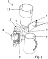
figure 2 représente une vue en perspective arrière du dispositif de lafigure 1 ; - la
figure 3 représente une vue éclatée en perspective de l'élément chauffant du dispositif de l'invention ; - la
figure 4 représente une vue en coupe d'un exemple de clapet obturateur du dispositif de l'invention ; - la
figure 5 représente une vue schématique du circuit de commande du dispositif de l'invention ; - la
figure 6 représente une vue d'un cycle de chauffe réalisé selon le procédé de l'invention et avec le dispositif de l'invention.
- the
figure 1 is a front perspective view of a liquid heater according to one embodiment of the invention; - the
figure 2 represents a rear perspective view of the device of thefigure 1 ; - the
figure 3 represents an exploded perspective view of the heating element of the device of the invention; - the
figure 4 represents a sectional view of an exemplary shutter valve of the device of the invention; - the
figure 5 represents a schematic view of the control circuit of the device of the invention; - the
figure 6 represents a view of a heating cycle carried out according to the method of the invention and with the device of the invention.
Comme annoncé précédemment, l'invention concerne un dispositif de fourniture de liquide chaud, ce liquide étant généralement de l'eau préalablement placée à température ambiante d'environ 20°C à 25°C (conditions pour lesquelles le dispositif est particulièrement adapté).As previously announced, the invention relates to a device for supplying hot liquid, this liquid being generally water previously placed at ambient temperature of about 20 ° C to 25 ° C (conditions for which the device is particularly suitable).
Le dispositif de fourniture d'un liquide 1 chaud représenté aux
Etant donné que le dispositif de l'invention sert à préparer des boissons par fourniture d'eau chaude, les parties du circuit de transport 2 qui- sont en contact avec le liquide chauffé, c'est-à-dire l'eau chaude, sont en matériau(x) alimentaire(s) tel(s) que de l'inox, du plastique (par exemple du PA chargé de verre). L'eau chauffée et mise en circulation selon le procédé de l'invention est délivrée dans un récipient tel qu'une tasse et est propre à être bue par l'utilisateur.Since the device of the invention serves to prepare drinks by supplying hot water, the parts of the
Le circuit de transport 2 possède une extrémité d'alimentation en liquide 3 reliée à un réservoir de liquide 15 par l'intermédiaire d'un clapet obturateur (décrit à la
Grâce à son réservoir, le dispositif de l'invention peut fonctionner sans avoir à être relié à un réseau externe d'alimentation en eau.Thanks to its reservoir, the device of the invention can operate without having to be connected to an external water supply network.
Une tasse est représentée en dessous de l'extrémité libre 4 du circuit de transport 2 pour recevoir le liquide chauffé et délivré.A cup is shown below the
Le circuit comprend également un élément de chauffe du liquide 8 disposé en série avec une pompe 14 et en aval de cette dernière.The circuit also comprises a
Cette pompe 14 est adaptée pour assurer la circulation de liquide dans le circuit 2 à un débit fixe donné D, c'est à dire un débit constant. Le positionnement de la pompe 14 entre le réservoir 15 et l'élément de chauffe 8 permet d'alimenter la pompe en eau tempérée ce qui accroît sa durée de vie. D'autre part, grâce à cette position le liquide se trouvant dans l'élément de chauffe est toujours en légère surpression puisque placé en aval de la pompe. Cette légère -surpression -permet d'avoir momentanément une température de chauffe proche de la température d'ébullition sans risquer la formation massive de vapeur dans le circuit.This
L'unité de commande est alimentée électriquement par un câble d'alimentation non représenté et relié au secteur. Comme cela est visible sur la
L'élément de chauffe 8 qui est représenté sur la
Le corps principal 9 présente une inertie thermique inférieure à celle de l'aluminium et l'élément complémentaire présente une résistance chauffante sérigraphiée sur sa face opposée 13 à celle en regard du corps principal.The main body 9 has a thermal inertia lower than that of aluminum and the complementary element has a screen-printed heating resistor on its face opposite to that facing the main body.
Par inertie thermique (Ith), on entend la capacité d'un corps à emmagasiner plus ou moins de chaleur, ce qui peut s'exprimer par le produit de la valeur de sa densité massique (p) par la valeur de sa capacité thermique spécifique (cp). ![]()
![]()
Selon l'invention, le corps principal est une sorte "d'isolant thermique" en ce que, lors d'une phase de chauffe, il prend beaucoup moins de calories que le liquide en circulation et cela à cause de sa faible inertie thermique.According to the invention, the main body is a kind of "thermal insulator" in that, during a heating phase, it takes a lot less calories than the circulating liquid and this because of its low thermal inertia.
Pour cela, ce corps principal 9 est réalisé en plastique.For this, this main body 9 is made of plastic.
Avantageusement, l'élément complémentaire présente un fort coefficient de conduction thermique transversal, par exemple supérieur à 40. Par coefficient de conduction thermique transversal (Cth), on entend le rapport de la valeur du coefficient de conductibilité thermique (À) du matériau de l'élément complémentaire de chauffe que divise la valeur de son épaisseur (e) exprimée en millimètre.![]()
![]()
En d'autres termes, l'élément complémentaire transmet très rapidement par conduction l'énergie calorifique de la résistance chauffante au liquide, car soit l'épaisseur de l'élément complémentaire est réduite, de l'ordre de 3mm pour un matériau comme l'aluminium à fort coefficient de conductibilité, soit l'épaisseur est très réduite, de l'ordre du millimètre, pour un matériau de moindre coefficient de conductibilité comme l'inox.In other words, the complementary element transmits very rapidly by conduction the heat energy of the heating resistor to the liquid, because either the thickness of the complementary element is reduced, of the order of 3 mm for a material such as aluminum with a high conductivity coefficient, ie the thickness is very small, of the order of one millimeter, for a material with a lower conductivity coefficient such as stainless steel.
Incidemment, le fait que la résistance chauffante soit de type sérigraphié et ceci en combinaison avec le bon coefficient de conduction thermique transversal fait que l'élément complémentaire de chauffe présente également une faible inertie thermique, diminuant les pertes énergétiques. Or, ce type d'élément de chauffe 8 ayant une résistance chauffante 12 sérigraphiée permet de réaliser une chauffe uniforme sur une grande surface en regard du liquide, ce qui augmente son efficacité de conductibilité thermique générale.Incidentally, the fact that the heating resistor is screen-printed type and this in combination with the good coefficient of transverse thermal conduction makes the complementary heating element also has a low thermal inertia, reducing energy losses. However, this type of
Autrement dit, l'élément de chauffe 8 comporte un corps principal 9 qui est relativement isolant thermiquement, et qui est recouvert par un élément complémentaire 10 chauffant rapidement. Cet élément complémentaire 10 transmet donc une énergie calorifique au liquide circulant dans l'espace qui le sépare du corps principal 9. Du fait du fort coefficient de transfert thermique par conduction de l'élément complémentaire, l'essentiel de l'énergie dissipée par la résistance sérigraphiée se transmet au liquide en circulation, plutôt que de s'accumuler dans l'élément complémentaire chauffant 10. De même, le corps principal de chauffe 9 possède une faible inertie thermique, de sorte qu'il emmagasine qu'une faible quantité d'énergie en provenance de l'élément complémentaire chauffant 10.In other words, the
Il s'ensuit que le liquide reçoit très rapidement et de manière quasi intégrale l'énergie calorifique en provenance de la résistance sérigraphiée 12, de sorte que le chauffage du liquide est quasi instantané. De même, le corps principal ne participe pratiquement pas aux phénomènes de chauffage du liquide, de sorte que lorsque le dispositif ne fonctionne pas, il n'est pas nécessaire de fournir une quantité d'énergie pour qu'il reste à une température suffisante.It follows that the liquid receives very quickly and almost completely the heat energy from the screen-printed
Autrement dit, la consommation du dispositif de chauffage en dehors des phases de chauffage proprement dites est nulle. De manière corollaire, la phase de chauffe de l'élément de chauffe 8 est extrêmement rapide dès le début de l'utilisation du dispositif, puisque le corps de chauffe n'a pas besoin de recevoir une quantité importante d'énergie pour arriver à température d'utilisation. Il n'y a donc pas de besoin d'avoir un phase de préchauffage avant que le moyen de commande 7 qui est un bouton marche arrêt ne soit actionné par l'utilisateur.In other words, the consumption of the heating device outside the heating phases themselves is zero. As a corollary, the heating phase of the
En pratique, l'élément de chauffe 8 peut avoir différentes géométries. Ainsi, dans une première forme de réalisation représentée sur la
Dans une autre forme de réalisation, le corps central peut être plat, et recevoir alors un élément chauffant plat également.In another embodiment, the central body may be flat, and then receive a flat heating element as well.
Pour augmenter l'efficacité du dispositif, on peut prévoir, comme c'est le cas sur la
Dans le même but, la résistance sérigraphiée 12 peut être avantageusement localisée à l'aplomb du canal de circulation du liquide.For the same purpose, the screen-printed
En pratique, lorsque l'élément de chauffe est de forme générale cylindrique, la rainure est hélicoïdale 21 comme sur la
Dans le même esprit, le corps principal de chauffe 9 est préférentiellement creux, de manière à encore limiter sa masse, donc son inertie thermique.In the same spirit, the main heating body 9 is preferably hollow, so as to further limit its mass, so its thermal inertia.
Le capteur de température C est agencé sur l'élément complémentaire.The temperature sensor C is arranged on the complementary element.
Du fait que l'élément complémentaire 10 possède une forte conductibilité transversale et que le corps principal 9 et l'élément complémentaire 10 présentent une faible inertie thermique, la régulation électrique et/ou électronique est particulièrement dynamique, quasi instantanée, faisant que le liquide sort à une température plutôt stable avec une consommation énergétique minimisée.Because the
La
Dans ce cas, l'élément de chauffe 8 comporte un corps principal central 9 associé à un élément complémentaire chauffant 10 sous la forme d'un manchon cylindrique. L'espace défini entre la face 11 extérieure du corps principal central 9 et la face intérieure du manchon 10, forme le volume en cylindre creux de circulation du liquide.In this case, the
Dans la forme illustrée, la face extérieure du corps principal 9 comporte une rainure hélicoïdale 4 qui permet de définir avec le manchon un cheminement du liquide autour du corps principal. Toutefois, dans d'autres formes de réalisation, non représentées, formes de réalisation, non représentées, la face extérieure du corps principal 9 peut être totalement cylindrique, de manière à définir avec le manchon un volume de circulation d'épaisseur constante, s'étendant le long du cylindre. D'autres variantes peuvent être envisagées sans sortir du cadre de l'invention définie par les revendications. En pratique, le corps principal central 9 est relié à une alimentation en eau froide, c'est à dire à la sortie d'eau de la pompe. Cette arrivée est reliée à la face extérieure (face 11 du corps principal) par un canal 19 sensiblement radial, qui débouche sur la face extérieure 11.In the form shown, the outer face of the main body 9 has a
Le corps principal central 9 est réalisé de préférence en matière plastique, ou plus généralement dans un matériau possédant une faible inertie thermique Ith, en tout cas inférieure à celle de l'aluminium de l'ordre de 2,30, de manière à n'emmagasiner qu'une faible partie de l'énergie de chauffage. Comme matériau susceptible de bien convenir dans la réalisation du corps principale 9 selon l'invention, on peut citer le polyamide (Ith=1,9), le polyacétal (Ith=2), le polypropylène (Ith=1,6), le poysulfone (Ith=1,4) ou le polycarbonate (Ith=1,5), ou le polyphénile sulfone PPS.The central main body 9 is preferably made of plastic material, or more generally of a material having a low thermal inertia Ith, in any case lower than that of aluminum of the order of 2.30, so that n ' store only a small portion of the heating energy. As a material likely to be suitable for producing the main body 9 according to the invention, mention may be made of polyamide (Ith = 1.9), polyacetal (Ith = 2), polypropylene (Ith = 1.6), poysulfone (Ith = 1.4) or polycarbonate (Ith = 1.5), or polyphenyl sulfone PPS.
Dans la forme illustrée à la
Dans cet exemple, la rainure 21 présente une profondeur de l'ordre de 3 millimètres, et une largeur d'environ 8 millimètres. Cette rainure 21, présente une géométrie hélicoïdale, d'un pas de 9 millimètres environ. En d'autres termes, la profondeur est plus faible que la largeur de telle sorte à "étaler" le liquide contre l'élément complémentaire chauffant 10 et ainsi favoriser le transfert de calories.In this example, the
De préférence, le manchon ou élément complémentaire 10 est réalisé de telle sorte à présenter un fort coefficient de conduction thermique transversal et une faible inertie thermique.Preferably, the sleeve or
L'épaisseur du manchon 10 est réduite au minimum en fonction du matériau de base pour diminuer cette inertie thermique, et pour augmenter les phénomènes de conduction. Parmi les matériaux donnant de bons résultats en termes de propriétés thermiques, on peut citer le cuivre, l'acier inoxydable, l'aluminium ou le verre. Il importe que le manchon 10 permette le dépôt d'une résistance électrique chauffante 12 sérigraphiée.The thickness of the
Le procédé de réalisation des pistes chauffantes consiste à sérigraphier une ou plusieurs couches de matériau isolant, puis une couche de pâte conductrice selon un chemin particulier, une couche pour former des plots de contact et enfin une ou plusieurs couches de matériau isolant. La puissance disponible peut être de l'ordre de 2000W à 3000W.The method of producing the heating tracks consists in screen printing one or more layers of insulating material, then a conductive paste layer according to a particular path, a layer for forming contact pads and finally one or more layers of insulating material. The available power can be of the order of 2000W to 3000W.
Cette résistance électrique 12 forme donc un ruban qui, dans la forme illustrée, est agencé sous forme de cercles transversaux avec décalage le long d'une même ligne longitudinale : toute la surface interne du manchon forme une plaque chauffante contre laquelle les rainures forcent le liquide à couler. Si désiré, la résistance sérigraphiée peut être hélicoïdale, et se trouver à l'aplomb des canaux définis par la rainure 21 du corps principal de chauffe 9. Dans ce cas, l'efficacité du chauffage et sa rapidité sont améliorées.This
Ainsi, pour un manchon / élément complémentaire 10 en inox ayant un diamètre extérieur de l'ordre de 45 mm, l'épaisseur du manchon 10 peut être avantageusement comprise entre 0,5 et 1,5 millimètres, de préférence entre 0,8 et 1 millimètre. Son coefficient de conduction thermique transversal Cth est alors de l'ordre de 60. L'avantage de l'inox est sa résistance à la corrosion et sa tenue à haute température facilitant la réalisation d'éléments chauffants plats.Thus, for a sleeve /
L'emploi d'un manchon / élément complémentaire 10 en aluminium est envisageable, mais avec des éléments chauffants sur support polyimide et des pâtes à plus faible température de cuisson. Par exemple, pour un manchon d'aluminium d'épaisseur de l'ordre de 3 millimètres permettant la réalisation d'éléments chauffants sérigraphiés, son coefficient de conduction thermique Cth est de l'ordre de 70.The use of a sleeve /
En pratique, la circulation de l'eau dans le cheminement le long de la face externe 11 du corps principal 9 s'effectue par l'intermédiaire de la pompe, mais cette circulation pourrait également s'effectuer sans pompe, par gravité, toutefois, la pompe présente l'avantage de fournir un débit constant.In practice, the flow of water in the path along the
Utilement, un capteur de température C, telle qu'une résistance CTN, est rapportée contre l'élément complémentaire chauffant et est branchée à l'unité de commande électronique 5 de la
Lors d'une première mise en marche avec un dispositif de chauffage froid, la régulation commande une pré-chauffe rapide, de l'ordre de 2 à 3 secondes, avant le début de la circulation d'eau. Cette pré-chauffe particulièrement rapide et quasiment non perceptible par l'utilisateur vient de la très faible inertie thermique globale du dispositif et de son efficacité de transfert thermique essentiellement vers l'eau contenue dans le circuit.When it is switched on for the first time with a cold heating device, the control commands a fast pre-heating, of the order of 2 to 3 seconds, before the start of the water circulation. This pre-heat particularly fast and almost unnoticeable by the user comes from the very low overall thermal inertia of the device and its thermal transfer efficiency essentially to the water contained in the circuit.
En pratique, les mesures effectuées avec ce type de dispositif de chauffe (équipé d'une résistance électrique de chauffe d'une puissance de 2 600 watts) permettent d'obtenir un chauffage d'environ 21 centilitres d'eau à une température comprise entre 70 et 80°C en 25 secondes seulement. La phase de pré-chauffe, seulement optionnelle, est particulièrement réduite, puisque le début d'écoulement peut intervenir au plus tard trois secondes environ après la mise en fonctionnement du dispositif de chauffe.In practice, the measurements made with this type of heating device (equipped with an electrical heating resistance of a power of 2600 watts) allow to obtain a heating of about 21 centilitres of water at a temperature between 70 and 80 ° C in just 25 seconds. The pre-heating phase, only optional, is particularly reduced, since the start of flow can occur no later than about three seconds after the heating device is put into operation.
Il ressort de ce qui précède que l'élément de chauffe 8 du dispositif conforme à l'invention présente de multiples avantages, et notamment celui d'avoir une inertie thermique particulièrement réduite. Il s'ensuit donc que l'eau circulant dans le dispositif, chauffe de manière quasi instantanée lors de la mise sous tension de la résistance chauffante 12.It follows from the foregoing that the
Lors de la mise hors tension de la résistance 12, l'élément de chauffe refroidit rapidement grâce à sa faible inertie thermique, préservant ainsi de l'échauffement l'environnement proche et facilitant également la régulation de la température de sortie.When the
La présence de la résistance sérigraphiée assure également une répartition de la puissance de chauffe sur une plus grande surface par rapport aux solutions existantes, de manière à optimiser le transfert thermique.The presence of the screen-printed resistance also ensures a distribution of the heating power over a larger area compared to the solutions to optimize heat transfer.
La
La liaison entre le réservoir et l'extrémité d'alimentation en liquide est réalisée par emboîtement de deux tubes male femelle.The connection between the reservoir and the liquid supply end is made by interlocking two male female tubes.
Le clapet comporte une portion conique d'étanchéité et une tige 22 venant en appui contre une portion complémentaire de l'extrémité d'alimentation lorsque le réservoir est assemblé avec l'extrémité d'alimentation.The valve comprises a conical sealing portion and a
Lors de l'assemblage du réservoir 15 avec l'extrémité d'alimentation 3, la tige 22 du clapet vient en butée contre l'extrémité d'alimentation 3 forçant ainsi le clapet à passer de sa position d'obturation à sa position d'ouverture. Inversement, lorsque l'on sépare le réservoir de l'extrémité d'alimentation 3, le clapet retourne dans sa position d'obturation, par gravité et/ou sous la pression d'un ressort agissant sur le clapet, ou encore par la pression du liquide du réservoir.When assembling the
Ainsi, le clapet obturateur 16 ouvre automatiquement le passage de fluide 17 du réservoir 15 vers la pompe 14 lorsque le réservoir 15 est relié à l'extrémité d'alimentation 3 et obture automatiquement ce passage 17 lorsque le réservoir 15 est débranché de l'extrémité d'alimentation 3.Thus, the
Eventuellement un filtre 18 peut être situé à l'entrée de l'extrémité d'alimentation afin d'éviter que des particules polluantes n'entrent dans le circuit de transport de liquide 2.Optionally a
La
L'unité de commande électronique 5 et/ou électrique comporte un moyen de commande 7 qui est un bouton de mise en route éventuellement couplé avec un moyen de présélection du volume de liquide à distribuer.The
Dans le cas où le dispositif de l'invention comporte un moyen de présélection du volume de liquide à distribuer, celui-ci est préférentiellement une minuterie ajustable manuellement et gérée par l'unité de commande 5. En effet étant donné que le débit délivré par la pompe du dispositif est un débit fixe (constant), alors le volume de liquide effectivement délivré dépend uniquement et directement du temps de fonctionnement de la pompe à débit fixe.In the case where the device of the invention comprises a preselection means of the volume of liquid to be dispensed, it is preferably a timer manually adjustable and managed by the
Par exemple en ajustant la minuterie à 7 secondes, la pompe sera alors alimentée pendant 7 secondes permettant de délivrer environ 7 centilitres d'eau chaude à débit constant.For example, by adjusting the timer to 7 seconds, the pump will be energized for 7 seconds to deliver about 7 centilitres of hot water at a constant rate.
L'unité de commande est également reliée à un capteur de température C et à deux commutateurs agissants respectivement sur l'alimentation électrique de la résistance chauffante 12 et de la pompe 14.The control unit is also connected to a temperature sensor C and two switches respectively acting on the power supply of the
De cette manière la pompe 14 et l'élément de chauffe 8 sont alimentés électriquement et commandés indépendamment l'un de l'autre par l'unité de commande 5.In this way the
Un générateur G (symbolisant l'alimentation électrique secteur) fournit l'énergie électrique à la résistance chauffante 12 et à la pompe 14 auxquels il est relié.A generator G (symbolizing the mains power supply) supplies the electrical energy to the
Le procédé de commande du dispositif est déclenché par une seule commande initiale exercée par l'utilisateur sur le moyen de commande 7 du dispositif. A réception de cette commande, l'unité de commande électronique gère l'ensemble des actions du procédé.
Le fonctionnement de ce circuit et la gestion de la chauffe et du débit par l'unité de commande électronique est décrite sur la
The operation of this circuit and the management of the heating and the flow by the electronic control unit is described on the
La
L'axe des ordonnées de gauche numéroté de 0 à 120°C correspond à la courbe de température en degrés Celsius indiquée par la CTN au cours du temps. Cette courbe est en fait une courbe représentative de la température du liquide ayant transité par l'élément de chauffe 8 en fonction du temps.The left ordinate axis numbered from 0 to 120 ° C corresponds to the temperature curve in degrees Celsius indicated by the NTC over time. This curve is in fact a curve representative of the temperature of the liquid having passed through the
La courbe D correspond au débit instantané de liquide généré par la pompe en fonction du temps. La valeur numérique correspondante à cette courbe D est indiquée- sur l'axe des ordonnées de droite numéroté de 0 à 1.2 centilitres par seconde. Dans cet exemple de fonctionnement le débit fixe de la pompe en fonctionnement est réglé à 1 centilitres par seconde.The curve D corresponds to the instantaneous flow rate of liquid generated by the pump as a function of time. The numerical value corresponding to this curve D is indicated on the right ordinate axis numbered from 0 to 1.2 centilitres per second. In this example of operation the fixed flow rate of the pump in operation is set to 1 centilitres per second.
La troisième courbe notée P est la courbe d'alimentation électrique de la résistance chauffante 12 en fonction du temps. Pour cette courbe aucune unité de puissance électrique n'est donnée. Toutefois les points de cette courbe situés en face du 0 de l'axe des ordonnées de gauche, indiquent que la résistance n'est pas alimentée. Inversement, les points de cette courbe situés en face du 78 de l'axe des ordonnées de gauche, indiquent que la résistance est alimentée avec une puissance électrique d'environ 2600 watts.The third curve marked P is the power supply curve of the
Les différentes mesures débutent au temps 0 secondes. Dans une première phase, allant de 0 à 4 secondes la température mesurée du liquide est de 25 °C, c'est la température ambiante du liquide à réchauffer.The different measurements start at
Au temps 4 secondes, l'utilisateur commande, par action sur le moyen de commande 7, la mise en route du dispositif (cet instant est symbolise par la référence « ON ») et ajuste un temps de minuterie « Tpmin » de 21 secondes qui correspond à 21 centilitres de liquide chauffé.At the
A ce temps 4 secondes, la résistance de chauffe 12 est alors alimentée à 2600 watts et la température du liquide donnée par la courbe « CTN (T) » s'élève rapidement au-delà de 25°C.At this
Du temps 4 secondes au temps 7 secondes, c'est à dire en 3 secondes la température du liquide s'est élevée de 25°C à 55°C.From
Le premier seuil de température T1 étant réglé à 55°C, l'unité de commande électronique qui reçoit les informations de température commande alors la mise en route de la pompe à son débit nominal de 1 centilitre par seconde pour une durée égale au temps de minuterie « Tpmin » sélectionné par l'utilisateur. Le liquide circule alors dans le circuit de transport pendant 21 secondes, c'est à dire du temps 7 secondes au temps 28 secondes. Il est à noter que le temps « Tpmin » intervient dans le procédé de commande de l'invention pour définir le temps de mise en fonction de la pompe à partir du passage du premier seuil T1.The first temperature threshold T1 being set at 55 ° C, the electronic control unit which receives the temperature information then controls the start of the pump at its nominal flow rate of 1 centiliter per second for a duration equal to the time of timer "Tpmin" selected by the user. The liquid then circulates in the transport circuit for 21 seconds, ie from 7 seconds to 28 seconds. It should be noted that the time "Tpmin" occurs in the control method of the invention to define the time of operation of the pump from the passage of the first threshold T1.
Malgré la mise en fonctionnement de la pompe, la température du liquide continue à s'accroître et arrive au second seuil T2 ajusté à 95°C au temps 10 secondes. Cette croissance de la température alors que la pompe est en fonctionnement est liée au fait que le ratio R de la puissance de chauffe exprimée en Watts divisée par le débit fixe donné de liquide généré par la pompe est supérieur à 2000.Despite the operation of the pump, the temperature of the liquid continues to increase and reaches the second threshold T2 adjusted to 95 ° C at
Dès la détection du second seuil T2 qui est réglé à 95°C, l'unité de commande électronique 5 coupe l'alimentation de la résistance de chauffe 12.
Du temps 10 secondes où intervient cette coupure au temps 11 secondes, la température continue à croître jusqu'à atteindre une pointe de 105°C au temps 11 secondes.Upon detection of the second threshold T2 which is set at 95 ° C, the
From the 10-second time this cut takes place to 11 seconds, the temperature continues to increase until reaching a peak of 105 ° C at
Au-delà de ce temps 11 secondes, la température du liquide diminue et passe à environ 89°C qui est le troisième seuil T3, au temps 13 secondes. Ce seuil T3 est préférentiellement calculé par soustraction d'une valeur de delta de température au second seuil T2. Ainsi, le troisième seuil T3 est toujours légèrement inférieur au second seuil T2, et dans le cas de l'exemple illustré, ce delta de température est de 1°C. Ce delta peut être compris entre 1°C et 10°C. Le delta de température est choisi le plus faible possible car plus ce delta est réduit et plus la variation de la température de l'eau à la sortie du dispositif de chauffe sera faible. Idéalement la température de l'eau à la sortie du dispositif devrait tendre vers une constante.Beyond this
A compter de T3, l'unité de commande ré-alimente alors la résistance électrique 12 comme cela est visible sur la courbe de puissance de chauffe P qui passe de 0 à 2600 watts au temps 13 secondes.From T3, the control unit then re-energizes the
La température du liquide continue à décroître par inertie thermique puis remonte alors rapidement après avoir eu une température minimale de 62 °C jusqu'à tendre vers une température proche de 90°C.The temperature of the liquid continues to decrease by thermal inertia and then rises rapidly after having a minimum temperature of 62 ° C until reaching a temperature close to 90 ° C.
Puis la fin du cycle de chauffe selon le procédé de l'invention s'interromps au temps 28 secondes où l'unité de commande coupe simultanément l'alimentation de la résistance de chauffe et de la pompe.Then the end of the heating cycle according to the method of the invention is interrupted at the time 28 seconds when the control unit simultaneously cuts the supply of the heating resistor and the pump.
Alternativement, le cycle de chauffe aurait pu être prolongé sans arrêter la pompe juste en continuant à mesurer l'évolution de la température du liquide et en alimentant la résistance lorsque la température décroît en dessous de T3 et en coupant cette alimentation lorsque la température du liquide croît au-dessus de T2.Alternatively, the heating cycle could have been prolonged without stopping the pump just by continuing to measure the evolution of the temperature of the liquid and by feeding the resistance when the temperature decreases below T3 and by cutting off this supply when the temperature of the liquid grows above T2.
Une option possible du procédé de commande du dispositif peut consister en ce qu'avant que la température du liquide T n'ait atteint le premier seuil de température T1, on fait circuler le liquide dans ledit dispositif de chauffe 1, à un débit minimum Dmin inférieur au débit nominal D.A possible option of the control method of the device may be that before the temperature of the liquid T has reached the first temperature threshold T1, the liquid is circulated in said
Cette caractéristique permet de distribuer une faible quantité de liquide non encore suffisamment chaud (inférieure à T1) dès que l'utilisateur effectue la commande, lui donnant ainsi l'impression que le dispositif est instantanément disponible. Dans tous les cas, la température du liquide sera supérieure au seuil T1 dans les 3 secondes suivant la commande de l'utilisateur.This characteristic makes it possible to dispense a small quantity of liquid that is not yet sufficiently hot (less than T1) as soon as the user makes the order, thus giving him the impression that the device is instantly available. In all cases, the temperature of the liquid will be higher than the threshold T1 within 3 seconds following the user's order.
Selon des options de l'invention, on choisit :
- le premier seuil de température T1 entre 50°C et 70°C et préférentiellement à 55°C ;
- le second seuil de température T2 entre 80°C et 100°C et préférentiellement à 90°C ;
- le troisième seuil de température T3 inférieur à T2 d'une valeur delta de température comprise
entre 1 et 10°C et préférentiellement de 1°C.
- the first temperature threshold T1 between 50 ° C and 70 ° C and preferably at 55 ° C;
- the second temperature threshold T2 between 80 ° C and 100 ° C and preferably at 90 ° C;
- the third temperature threshold T3 less than T2 of a temperature delta value of between 1 and 10 ° C. and preferably of 1 ° C.
Claims (21)
- Method for preparing drinks by supplying hot water by means of a device for preparing drinks comprising a liquid transport circuit (2) comprising:- a heating element (8) having a heating resistance (12);- a pump (14) arranged in series with the heating element (8) and adapted to provide for the circulation of liquid in the circuit (2),- said device for preparing drinks comprising an electronic control unit (5) provided with a control means (7),the method, after actuating by a user of the control means (7), comprises the following steps:- liquid is heated by supplying the heating resistance at a predefined average electrical power until a first predetermined temperature threshold (T1),- the heating of the liquid is maintained,- a ratio (R) is predefined between said predefined average electrical power and a given constant nominal rate (D), with the ratio (R) having a constant and predefined value between 2000 and 4000, with the predefined average electrical power of the heating resistance (12) being expressed in Watts and the given constant nominal rate (D) being expressed in centilitres per second,characterised in that- as soon as the first predetermined temperature threshold (T1) is reached, the liquid for the drink is made to circulate in said heating element (8), with the given constant nominal rate (D), said given constant nominal rate (D) being less than 2 cl/s,- the predefined average electrical power of the heating resistance (12) is less than 3500 Watts,- during the step of circulation of the liquid in the heating element (8), the liquid is heated by the heating resistance (12) to a second temperature threshold (T2) and- the putting into circulation of the liquid in the heating element is carried out by turning on the pump (14) at its given constant nominal rate (D) for a duration equal to a timer time "Tpmin" selected by the user, said "Tpmin" time defining the starting up time of the pump starting from the crossing of the first threshold (T1).
- Method according to claim 1, characterised in that said given constant nominal rate (D) is between 0.5 and 1.5 cl/second.
- Method according to any of claims 1 to 2, characterised in that the power supply of the heating resistance is cut off as soon as the measured temperature (T) is greater than the second threshold (T2), while still maintaining the circulation of the liquid, and the circulation of the fluid is cut off when the desired quantity of liquid has been supplied to the user.
- Method according to claim 3, characterised in that after having cut off the power supply of the heating resistance (12) while still maintaining the circulation of the liquid, the heating resistance (12) is supplied again as soon as the measured temperature (T) falls below a third temperature threshold (T3) that is less than the second (T2) and greater than the first (T1) and, according to the case, the cut off / supplying again cycle of the heating resistance is started again until the user has been supplied with the desired quantity of liquid.
- Method according to any of claims 1 to 4, characterised in that before the temperature of the liquid (T) has reached the first temperature threshold (T1), the liquid for the drink is made to circulate in said heating device (1), at a low rate (Dmin) less than the nominal rate (D).
- Method according to any of claims 1 to 5, characterised in that the first temperature threshold (T1) is between 50°C and 70°C and is preferably 55°C.
- Method according to any of claims 3 to 6, characterised in that the second temperature threshold (T2) is between 80°C and 100°C and is preferably 90°C.
- Method according to any of claims 4 or 7, combined with claims 5 and 6, characterised in that the third temperature threshold (T3) is less than the second threshold (T2) by a delta value between 1 and 10°C and preferably 1°C.
- Method according to any of claims 1 to 8, characterised in that the pump (14) and the heating element (8) are controlled independently one from the other, by the electronic control unit (5) provided with a control means (7) and with a source of electrical power, with the method being triggered by a single initial control exerted by the user on the control means (7), and upon receiving this control, the electronic control unit manages all of the actions of the method.
- Device (1) for preparing drinks by supplying hot water comprising:- a liquid transport circuit (2);- an electronic control unit (5) provided with a source of electrical power and with a means for controlling the device (7);with the transport circuit (2) comprising:a heating element of the liquid (8) comprising a heating resistance (12), with the heating element being arranged in series with a pump (14) adapted to provide for the circulation of liquid in the circuit (2) at a given constant nominal rate (D), the pump (14) and the heating element (8) being electrically powered and controlled independently from one another by the control unit (5); the pump and the heating element are dimensioned in such a way that the ratio (R) of the predefined average electrical power (P) of the heating resistance (12), expressed in Watts, divided by the given constant nominal rate (D) able to be provided by the pump (14) of the transport circuit (2) and expressed in centilitres per second, has a constant and predefined value between 2000 and 4000, characterised in thatthe heating resistance (12) is configured to heat the liquid to a first temperature threshold (T1) and to a second temperature threshold (T2) during the circulation of the liquid in the circuit (2) via the pump (14) at its given constant nominal rate (D) for a duration equal to a timer time "Tpmin" selected by the user, said "Tpmin" time defining the starting up time of the pump starting from the crossing of the first threshold T1, and in that the predefined average electrical power of the heating resistance (12) is less than 3500 Watts, and in that the electronic control unit (5) is configured to manage all of the actions of a method according to claim 9.
- Device (1) according to claim 10, characterised in that the heating element comprises a main body (9), associated with an additional element (10) covering one face of the main body (9) in order to define a volume of circulation of the liquid, said additional element (10) having a heating resistance (12) silk screened on its face opposite (13) that facing the main body (9).
- Device (1) according to any of claims 10 to 11, characterised in that the heating resistance (12) is controlled all-or-nothing by the control unit (5).
- Device (1) according to any of claims 10 to 12, characterised in that it comprises a temperature sensor (C) connected to the control unit (5) and arranged to capture a temperature (T) on a portion of the circuit located between the heating element (8) and a free end (4) of the liquid transport circuit (2).
- Device (1) according to claim 13, characterised in that the temperature sensor (C) is a Negative Temperature Coefficient thermistor (N.T.C).
- Device (1) according to any of claims 10 to 13, characterised in that the transport circuit (2) comprises a reservoir of liquid (15) connected in series with the pump (14) via a supplying end of the circuit (3) and the circuit (2) with liquid to be heated.
- Device (1) according to claim 15, characterised in that said reservoir (15) is removable and provided with a gate valve (16) that automatically opens a passage of fluid (17) from the reservoir (15) to the pump (14) when the reservoir (15) is connected to the supplying end (3) and automatically opens this passage (17) when the reservoir (15) is disconnected from the supplying end (3).
- Device (1) according to any of claims 11 to 16, characterised in that the main body has a thermal inertia less than that of aluminium.
- Device (1) according to any of claims 11 to 17, characterised in that the additional element (10) is made from a metal material that has a transverse thermal conductivity coefficient (Cth) greater than 40.
- Device (1) according to any of claims 11 to 18 combined with claim 14, characterised in that the main body (9) comprises a groove that makes it possible to define with the additional element (10) a channel (4) for the circulation of the liquid.
- Device (1) according to claim 19, characterised in that the main body (1) is flat and in that the groove has the shape of a spiral.
- Device (1) according to any of claims 11 to 20 combined with claim 14, characterised in that the main body (9) is cylindrical, and receives on its outer face the additional element (10) in the form of a sleeve.
Applications Claiming Priority (2)
| Application Number | Priority Date | Filing Date | Title |
|---|---|---|---|
| FR0412101A FR2878023B1 (en) | 2004-11-15 | 2004-11-15 | METHOD AND DEVICE FOR PROVIDING HOT WATER |
| PCT/FR2005/002820 WO2006051226A1 (en) | 2004-11-15 | 2005-11-14 | Method and device for supplying hot water |
Publications (2)
| Publication Number | Publication Date |
|---|---|
| EP1812758A1 EP1812758A1 (en) | 2007-08-01 |
| EP1812758B1 true EP1812758B1 (en) | 2018-05-02 |
Family
ID=34951504
Family Applications (1)
| Application Number | Title | Priority Date | Filing Date |
|---|---|---|---|
| EP05817451.7A Active EP1812758B1 (en) | 2004-11-15 | 2005-11-14 | Method and device for supplying hot water |
Country Status (10)
| Country | Link |
|---|---|
| US (1) | US8503870B2 (en) |
| EP (1) | EP1812758B1 (en) |
| JP (1) | JP2008519625A (en) |
| KR (1) | KR101246417B1 (en) |
| CN (1) | CN100578109C (en) |
| AU (1) | AU2005303625B2 (en) |
| BR (1) | BRPI0517838A (en) |
| FR (1) | FR2878023B1 (en) |
| RU (1) | RU2363899C2 (en) |
| WO (1) | WO2006051226A1 (en) |
Families Citing this family (37)
| Publication number | Priority date | Publication date | Assignee | Title |
|---|---|---|---|---|
| FR2901955B1 (en) * | 2006-06-05 | 2010-03-26 | Seb Sa | HOUSEHOLD APPLIANCE FOR LIQUID HEATING |
| JP5022497B2 (en) * | 2007-12-20 | 2012-09-12 | コーテックス テクストロン ジーエムビーエイチ アンド シーオー ケージー | Fluid heater |
| FR2956309B1 (en) * | 2010-02-15 | 2012-07-20 | Seb Sa | FAST BOILER AND HOUSEHOLD APPLIANCE COMPRISING SUCH BOILER |
| US8499684B1 (en) * | 2011-02-25 | 2013-08-06 | Upkar Premraj | Cupcake/muffin hole maker |
| USD677510S1 (en) | 2011-06-16 | 2013-03-12 | Calphalon Corporation | Coffee maker |
| EP2570056A1 (en) * | 2011-09-13 | 2013-03-20 | Jura Elektroapparate AG | Method for creating a coffee drink and coffee machine for carrying out the method |
| CN102353150A (en) * | 2011-09-30 | 2012-02-15 | 浙江绍兴苏泊尔生活电器有限公司 | Quick heater with variable heating cavity capacity |
| CN102349794A (en) * | 2011-09-30 | 2012-02-15 | 浙江绍兴苏泊尔生活电器有限公司 | Simple cooling device |
| FR2983692B1 (en) * | 2011-12-07 | 2014-07-25 | Seb Sa | HEATING DEVICE FOR MAKING BOILING LIQUID AND BEVERAGE PREPARING APPARATUS HAVING SUCH A DEVICE |
| ITRE20110109A1 (en) * | 2011-12-07 | 2013-06-08 | Redox S R L | ENERGY SAVING COFFEE MACHINE |
| ES2473115T3 (en) * | 2011-12-15 | 2014-07-03 | Nestec S.A. | Beverage dispenser with improved mounting of outlet tubes |
| RU2595608C2 (en) * | 2011-12-29 | 2016-08-27 | Конинклейке Филипс Н.В. | Method and device for preparing a beverage from a solvent and ingredients |
| KR101906340B1 (en) * | 2011-12-30 | 2018-10-11 | 코웨이 주식회사 | Apparatus for supplying hot water and method for the same |
| DE102012200949A1 (en) * | 2012-01-24 | 2013-07-25 | BSH Bosch und Siemens Hausgeräte GmbH | Tank outlet connecting device for beverage preparation device |
| KR101372256B1 (en) * | 2012-02-29 | 2014-03-10 | 한라비스테온공조 주식회사 | Cooling-water heating type heater |
| US9327216B2 (en) | 2012-11-12 | 2016-05-03 | Whirlpool Corporation | Customizable multi-stage water treatment system |
| US9314716B2 (en) | 2012-11-12 | 2016-04-19 | Whirlpool Corporation | Customizable multi-stage water treatment assembly |
| US9889478B2 (en) | 2012-11-12 | 2018-02-13 | Whirlpool Corporation | Consumable descaling cartridges for a refrigerator appliance |
| US9320993B2 (en) | 2012-11-12 | 2016-04-26 | Whirlpool Corporation | Filter housing for small media |
| WO2014195842A2 (en) * | 2013-06-02 | 2014-12-11 | Heatex Ltd. | A device and a method for the preparation of hot liquid or steam |
| CN103344348B (en) * | 2013-07-04 | 2015-11-25 | 长沙市博巨兴电子科技有限公司 | Electromagnetic oven water opens detection method and device |
| CN104776603A (en) * | 2014-01-13 | 2015-07-15 | 吴燕珊 | Temperature control device |
| CN104791988A (en) * | 2014-01-17 | 2015-07-22 | 吴燕珊 | Volume-variable water heater |
| US20160000252A1 (en) | 2014-07-02 | 2016-01-07 | As Wilfa | Pump and heating method and arrangement for coffee brewing |
| CN104116408B (en) * | 2014-07-18 | 2017-02-01 | 允慧科技(上海)有限公司 | Air lift pumping device, fluid container comprising air lift pumping device, and tea making machine |
| PL3254034T3 (en) * | 2015-02-05 | 2022-04-25 | Giorgio TORCHIO | Capillary proximity heater with high energy saving equipped upstream of a microfiltration apparatus for the elimination of calcareuos particles present in fluids and downstream of a nozzle or closed circuit |
| ITUB20155938A1 (en) * | 2015-11-26 | 2017-05-26 | Vibiemme Srl | BREWING GROUP FOR HOT DRINKS, PARTICULARLY FOR COFFEE? ESPRESSO, AND COFFEE MACHINE? INCLUDING THE SUPPLY GROUP |
| US11737596B2 (en) * | 2016-03-24 | 2023-08-29 | Charles D. MacPherson | Coffee-based beverage preparation system and methods for using the same |
| ES1160808Y (en) * | 2016-06-16 | 2016-10-04 | Teylor Intelligent Processes Sl | AUTONOMOUS HYDRAULIC UNIT |
| UA125339C2 (en) * | 2016-08-24 | 2022-02-23 | Інностім Свісс Са | Device and method to produce instant hot water |
| US11470998B2 (en) * | 2017-01-10 | 2022-10-18 | Nuwave, Llc | Automatic beverage maker reservoir heating system |
| IT201700033574A1 (en) * | 2017-03-27 | 2018-09-27 | Ali Group Srl Carpigiani | CONNECTOR FOR CONNECTION OF A CONTAINER OF LIQUID OR SEMI-LIQUID FOOD PRODUCTS AND MACHINE INCLUDING THE CONNECTOR AND CONTAINER. |
| CN109820422A (en) * | 2017-11-23 | 2019-05-31 | 德隆奇电器单一股东有限责任公司 | Prepare the machine and method of beverage |
| CN108477998A (en) * | 2018-02-01 | 2018-09-04 | 佛山市顺德区美的饮水机制造有限公司 | Liquid-heating method and device |
| FR3101970B1 (en) * | 2019-10-15 | 2021-10-01 | Seb Sa | Reinforced electrical safety beverage dispensing machine control circuit |
| CN112450736A (en) * | 2020-11-26 | 2021-03-09 | 珠海格力电器股份有限公司 | Cooking control method and device, cooking equipment and readable storage medium |
| CN112963962B (en) * | 2021-02-08 | 2022-10-28 | 杭州商芯物联网科技有限公司 | Constant-temperature water heating device of hot wet tissue machine and control method |
Citations (13)
| Publication number | Priority date | Publication date | Assignee | Title |
|---|---|---|---|---|
| GB2035764A (en) | 1978-11-22 | 1980-06-18 | Mars Ltd | Electric water heater |
| EP0380947A1 (en) | 1989-01-30 | 1990-08-08 | ILLYCAFFE S.p.A. | Coffee machine |
| US5408917A (en) | 1992-07-01 | 1995-04-25 | Luessi; Andre | Appliance for preparation of hot drinks |
| US5778765A (en) | 1995-12-30 | 1998-07-14 | Braun Aktiengesellschaft | Beverage brewing apparatus |
| GB2324014A (en) | 1997-04-01 | 1998-10-07 | Caradon Mira Ltd | Printed circuit instantaneous electric water heaters |
| US5865097A (en) | 1996-05-14 | 1999-02-02 | Smitdesign B.V. | Apparatus for heating water, intended for the preparation of hot beverages |
| EP0935938A1 (en) | 1998-02-13 | 1999-08-18 | Seb S.A. | Electric espresso coffeemachine with thermal regulation mean |
| US6000317A (en) | 1996-12-23 | 1999-12-14 | U.S. Philips Corporation | Coffee maker |
| GB2340590A (en) | 1998-08-14 | 2000-02-23 | Rosecharm Limited | Electric flow boiler |
| WO2001054551A1 (en) * | 2000-01-24 | 2001-08-02 | Societe Des Produits Nestle S.A. | A liquid heating module, a system comprising said module and a process for heating liquid |
| US20020051632A1 (en) | 2000-10-02 | 2002-05-02 | Hans Kodden | Water flow heater |
| WO2004034857A1 (en) | 2002-10-14 | 2004-04-29 | Vallid Limited | Hot water supply for making a brewed beverage |
| FR2855359A1 (en) | 2003-05-19 | 2004-11-26 | Seb Sa | Liquid e.g. water, heating device for e.g. electric coffee maker, has main body with thermal inertia lower than that of aluminum and storing calorific energy from thermal resistor of complementary heating unit |
Family Cites Families (10)
| Publication number | Priority date | Publication date | Assignee | Title |
|---|---|---|---|---|
| JPS5450093A (en) * | 1977-09-28 | 1979-04-19 | Osaka Soda Co Ltd | Chlorination of polyolefin |
| FR2420726A1 (en) * | 1978-03-21 | 1979-10-19 | Commissariat Energie Atomique | DEVICE FOR BRINGING A LIQUID TO A GIVEN TEMPERATURE |
| JPS61131713A (en) * | 1984-11-13 | 1986-06-19 | ソシエテ デ プロデユイ ネツスル ソシエテ アノニム | Electric pot apparatus |
| JPH07243700A (en) * | 1994-03-09 | 1995-09-19 | Yamatake Honeywell Co Ltd | Method for controlling temperature of hot water feeding device |
| GB2305233A (en) * | 1995-09-15 | 1997-04-02 | Welwyn Components Ltd | Water heater with thick film printed circuit |
| KR100224296B1 (en) | 1996-04-13 | 1999-10-15 | 배길성 | Heating apparatus for automatic vending machine of wondo coffee |
| DE19732414A1 (en) * | 1997-07-30 | 1999-02-04 | Suhl Elektro & Hausgeraetewerk | Throughflow heater for heating liquids e.g. water |
| ATE299350T1 (en) | 1999-11-02 | 2005-07-15 | Nestle Sa | DEVICE AND METHOD FOR CONTINUOUS HEATING OF A CONSTANT TEMPERATURE BEVERAGE |
| GB0016313D0 (en) * | 2000-07-03 | 2000-08-23 | Dass Manufacturing Ltd | Beverage dispenser |
| CN1204365C (en) * | 2001-04-20 | 2005-06-01 | 坂本笃信 | Electric water heater, liquid heater, and steam generator |
-
2004
- 2004-11-15 FR FR0412101A patent/FR2878023B1/en active Active
-
2005
- 2005-11-14 WO PCT/FR2005/002820 patent/WO2006051226A1/en active Application Filing
- 2005-11-14 BR BRPI0517838-0A patent/BRPI0517838A/en not_active Application Discontinuation
- 2005-11-14 CN CN200580038967A patent/CN100578109C/en not_active Expired - Fee Related
- 2005-11-14 US US11/719,275 patent/US8503870B2/en active Active
- 2005-11-14 EP EP05817451.7A patent/EP1812758B1/en active Active
- 2005-11-14 RU RU2007122394/12A patent/RU2363899C2/en not_active IP Right Cessation
- 2005-11-14 KR KR1020077013077A patent/KR101246417B1/en not_active IP Right Cessation
- 2005-11-14 AU AU2005303625A patent/AU2005303625B2/en not_active Ceased
- 2005-11-14 JP JP2007540683A patent/JP2008519625A/en active Pending
Patent Citations (13)
| Publication number | Priority date | Publication date | Assignee | Title |
|---|---|---|---|---|
| GB2035764A (en) | 1978-11-22 | 1980-06-18 | Mars Ltd | Electric water heater |
| EP0380947A1 (en) | 1989-01-30 | 1990-08-08 | ILLYCAFFE S.p.A. | Coffee machine |
| US5408917A (en) | 1992-07-01 | 1995-04-25 | Luessi; Andre | Appliance for preparation of hot drinks |
| US5778765A (en) | 1995-12-30 | 1998-07-14 | Braun Aktiengesellschaft | Beverage brewing apparatus |
| US5865097A (en) | 1996-05-14 | 1999-02-02 | Smitdesign B.V. | Apparatus for heating water, intended for the preparation of hot beverages |
| US6000317A (en) | 1996-12-23 | 1999-12-14 | U.S. Philips Corporation | Coffee maker |
| GB2324014A (en) | 1997-04-01 | 1998-10-07 | Caradon Mira Ltd | Printed circuit instantaneous electric water heaters |
| EP0935938A1 (en) | 1998-02-13 | 1999-08-18 | Seb S.A. | Electric espresso coffeemachine with thermal regulation mean |
| GB2340590A (en) | 1998-08-14 | 2000-02-23 | Rosecharm Limited | Electric flow boiler |
| WO2001054551A1 (en) * | 2000-01-24 | 2001-08-02 | Societe Des Produits Nestle S.A. | A liquid heating module, a system comprising said module and a process for heating liquid |
| US20020051632A1 (en) | 2000-10-02 | 2002-05-02 | Hans Kodden | Water flow heater |
| WO2004034857A1 (en) | 2002-10-14 | 2004-04-29 | Vallid Limited | Hot water supply for making a brewed beverage |
| FR2855359A1 (en) | 2003-05-19 | 2004-11-26 | Seb Sa | Liquid e.g. water, heating device for e.g. electric coffee maker, has main body with thermal inertia lower than that of aluminum and storing calorific energy from thermal resistor of complementary heating unit |
Also Published As
| Publication number | Publication date |
|---|---|
| CN101057113A (en) | 2007-10-17 |
| AU2005303625A1 (en) | 2006-05-18 |
| RU2363899C2 (en) | 2009-08-10 |
| US20100221394A1 (en) | 2010-09-02 |
| JP2008519625A (en) | 2008-06-12 |
| EP1812758A1 (en) | 2007-08-01 |
| FR2878023A1 (en) | 2006-05-19 |
| FR2878023B1 (en) | 2007-04-13 |
| BRPI0517838A (en) | 2008-10-21 |
| US8503870B2 (en) | 2013-08-06 |
| KR20070089802A (en) | 2007-09-03 |
| CN100578109C (en) | 2010-01-06 |
| KR101246417B1 (en) | 2013-03-21 |
| WO2006051226A1 (en) | 2006-05-18 |
| RU2007122394A (en) | 2008-12-20 |
| AU2005303625B2 (en) | 2010-03-04 |
Similar Documents
| Publication | Publication Date | Title |
|---|---|---|
| EP1812758B1 (en) | Method and device for supplying hot water | |
| EP1625772B1 (en) | Device for heating a liquid for a domestic appliance, domestic appliance fitted with said device | |
| EP1945074B1 (en) | Device for heating fluid in a household appliance | |
| EP1809151B1 (en) | Device and method for heating a liquid | |
| EP1220631A1 (en) | Temperature regulation of an espresso coffee maker | |
| EP0935938A1 (en) | Electric espresso coffeemachine with thermal regulation mean | |
| EP2054783A2 (en) | Method and device for controlling a household electrical apparatus for heating liquid | |
| EP1681967A1 (en) | Steam cooking method and oven with an improved water supply | |
| EP0540440A1 (en) | Improved injector device for a coffee machine, comprising a temperature regulating unit for the hot water, located close to the injection point | |
| EP0616786B1 (en) | Coffee brewer with water return conduct | |
| EP1147730A1 (en) | Espresso type coffee machine with two thermostats | |
| FR3072012A1 (en) | COFFEE MACHINE USING A THERMAL PUMP AND MEANS FOR CONTROLLING THE SUPPLY TIME OF A HEATING ELEMENT OF A BOILER | |
| EP1143836A1 (en) | Heating base for electric household appliance for heating liquids | |
| WO2001098852A1 (en) | Temperature control method for a depilatory apparatus wax reservoir | |
| FR2757029A1 (en) | HAND MELT DISPENSER, IN PARTICULAR HAIR REMOVAL | |
| FR2933858A1 (en) | APPARATUS FOR PREPARING HOT WATER HAVING A HOT HOLDING DEVICE. | |
| FR2803990A1 (en) | Depilatory wax applicator has heater with power decreasing in stages as volume of wax in reservoir reduces | |
| FR2830925A1 (en) | AUTOMATIC HOT WATER DISTRIBUTION SYSTEM FOR THE PREPARATION OF INFUSED BEVERAGES | |
| EP2054784A2 (en) | Method and device for controlling a household electrical apparatus for heating liquid | |
| FR2787693A1 (en) | Heated base unit for a household appliance for heating liquids, comprises a bi-metallic switching strip that operates the heating element in a high and low temperature mode of operation | |
| BE401882A (en) |
Legal Events
| Date | Code | Title | Description |
|---|---|---|---|
| PUAI | Public reference made under article 153(3) epc to a published international application that has entered the european phase |
Free format text: ORIGINAL CODE: 0009012 |
|
| 17P | Request for examination filed |
Effective date: 20070524 |
|
| AK | Designated contracting states |
Kind code of ref document: A1 Designated state(s): AT BE BG CH CY CZ DE DK EE ES FI FR GB GR HU IE IS IT LI LT LU LV MC NL PL PT RO SE SI SK TR |
|
| DAX | Request for extension of the european patent (deleted) | ||
| TPAC | Observations filed by third parties |
Free format text: ORIGINAL CODE: EPIDOSNTIPA |
|
| 17Q | First examination report despatched |
Effective date: 20120412 |
|
| RAP1 | Party data changed (applicant data changed or rights of an application transferred) |
Owner name: SEB S.A. |
|
| GRAP | Despatch of communication of intention to grant a patent |
Free format text: ORIGINAL CODE: EPIDOSNIGR1 |
|
| INTG | Intention to grant announced |
Effective date: 20170622 |
|
| GRAJ | Information related to disapproval of communication of intention to grant by the applicant or resumption of examination proceedings by the epo deleted |
Free format text: ORIGINAL CODE: EPIDOSDIGR1 |
|
| GRAL | Information related to payment of fee for publishing/printing deleted |
Free format text: ORIGINAL CODE: EPIDOSDIGR3 |
|
| GRAS | Grant fee paid |
Free format text: ORIGINAL CODE: EPIDOSNIGR3 |
|
| GRAP | Despatch of communication of intention to grant a patent |
Free format text: ORIGINAL CODE: EPIDOSNIGR1 |
|
| INTC | Intention to grant announced (deleted) | ||
| INTG | Intention to grant announced |
Effective date: 20171020 |
|
| GRAA | (expected) grant |
Free format text: ORIGINAL CODE: 0009210 |
|
| STAA | Information on the status of an ep patent application or granted ep patent |
Free format text: STATUS: THE PATENT HAS BEEN GRANTED |
|
| AK | Designated contracting states |
Kind code of ref document: B1 Designated state(s): AT BE BG CH CY CZ DE DK EE ES FI FR GB GR HU IE IS IT LI LT LU LV MC NL PL PT RO SE SI SK TR |
|
| REG | Reference to a national code |
Ref country code: GB Ref legal event code: FG4D Free format text: NOT ENGLISH |
|
| REG | Reference to a national code |
Ref country code: CH Ref legal event code: EP Ref country code: AT Ref legal event code: REF Ref document number: 995700 Country of ref document: AT Kind code of ref document: T Effective date: 20180515 |
|
| REG | Reference to a national code |
Ref country code: DE Ref legal event code: R096 Ref document number: 602005053911 Country of ref document: DE |
|
| REG | Reference to a national code |
Ref country code: IE Ref legal event code: FG4D Free format text: LANGUAGE OF EP DOCUMENT: FRENCH |
|
| REG | Reference to a national code |
Ref country code: NL Ref legal event code: MP Effective date: 20180502 |
|
| REG | Reference to a national code |
Ref country code: LT Ref legal event code: MG4D |
|
| PG25 | Lapsed in a contracting state [announced via postgrant information from national office to epo] |
Ref country code: LT Free format text: LAPSE BECAUSE OF FAILURE TO SUBMIT A TRANSLATION OF THE DESCRIPTION OR TO PAY THE FEE WITHIN THE PRESCRIBED TIME-LIMIT Effective date: 20180502 Ref country code: ES Free format text: LAPSE BECAUSE OF FAILURE TO SUBMIT A TRANSLATION OF THE DESCRIPTION OR TO PAY THE FEE WITHIN THE PRESCRIBED TIME-LIMIT Effective date: 20180502 Ref country code: SE Free format text: LAPSE BECAUSE OF FAILURE TO SUBMIT A TRANSLATION OF THE DESCRIPTION OR TO PAY THE FEE WITHIN THE PRESCRIBED TIME-LIMIT Effective date: 20180502 Ref country code: BG Free format text: LAPSE BECAUSE OF FAILURE TO SUBMIT A TRANSLATION OF THE DESCRIPTION OR TO PAY THE FEE WITHIN THE PRESCRIBED TIME-LIMIT Effective date: 20180802 Ref country code: FI Free format text: LAPSE BECAUSE OF FAILURE TO SUBMIT A TRANSLATION OF THE DESCRIPTION OR TO PAY THE FEE WITHIN THE PRESCRIBED TIME-LIMIT Effective date: 20180502 |
|
| PG25 | Lapsed in a contracting state [announced via postgrant information from national office to epo] |
Ref country code: LV Free format text: LAPSE BECAUSE OF FAILURE TO SUBMIT A TRANSLATION OF THE DESCRIPTION OR TO PAY THE FEE WITHIN THE PRESCRIBED TIME-LIMIT Effective date: 20180502 Ref country code: GR Free format text: LAPSE BECAUSE OF FAILURE TO SUBMIT A TRANSLATION OF THE DESCRIPTION OR TO PAY THE FEE WITHIN THE PRESCRIBED TIME-LIMIT Effective date: 20180803 Ref country code: NL Free format text: LAPSE BECAUSE OF FAILURE TO SUBMIT A TRANSLATION OF THE DESCRIPTION OR TO PAY THE FEE WITHIN THE PRESCRIBED TIME-LIMIT Effective date: 20180502 |
|
| REG | Reference to a national code |
Ref country code: AT Ref legal event code: MK05 Ref document number: 995700 Country of ref document: AT Kind code of ref document: T Effective date: 20180502 |
|
| PG25 | Lapsed in a contracting state [announced via postgrant information from national office to epo] |
Ref country code: PT Free format text: LAPSE BECAUSE OF FAILURE TO SUBMIT A TRANSLATION OF THE DESCRIPTION OR TO PAY THE FEE WITHIN THE PRESCRIBED TIME-LIMIT Effective date: 20180903 |
|
| PG25 | Lapsed in a contracting state [announced via postgrant information from national office to epo] |
Ref country code: DK Free format text: LAPSE BECAUSE OF FAILURE TO SUBMIT A TRANSLATION OF THE DESCRIPTION OR TO PAY THE FEE WITHIN THE PRESCRIBED TIME-LIMIT Effective date: 20180502 Ref country code: AT Free format text: LAPSE BECAUSE OF FAILURE TO SUBMIT A TRANSLATION OF THE DESCRIPTION OR TO PAY THE FEE WITHIN THE PRESCRIBED TIME-LIMIT Effective date: 20180502 Ref country code: PL Free format text: LAPSE BECAUSE OF FAILURE TO SUBMIT A TRANSLATION OF THE DESCRIPTION OR TO PAY THE FEE WITHIN THE PRESCRIBED TIME-LIMIT Effective date: 20180502 Ref country code: SK Free format text: LAPSE BECAUSE OF FAILURE TO SUBMIT A TRANSLATION OF THE DESCRIPTION OR TO PAY THE FEE WITHIN THE PRESCRIBED TIME-LIMIT Effective date: 20180502 Ref country code: CZ Free format text: LAPSE BECAUSE OF FAILURE TO SUBMIT A TRANSLATION OF THE DESCRIPTION OR TO PAY THE FEE WITHIN THE PRESCRIBED TIME-LIMIT Effective date: 20180502 Ref country code: EE Free format text: LAPSE BECAUSE OF FAILURE TO SUBMIT A TRANSLATION OF THE DESCRIPTION OR TO PAY THE FEE WITHIN THE PRESCRIBED TIME-LIMIT Effective date: 20180502 Ref country code: RO Free format text: LAPSE BECAUSE OF FAILURE TO SUBMIT A TRANSLATION OF THE DESCRIPTION OR TO PAY THE FEE WITHIN THE PRESCRIBED TIME-LIMIT Effective date: 20180502 |
|
| REG | Reference to a national code |
Ref country code: DE Ref legal event code: R026 Ref document number: 602005053911 Country of ref document: DE |
|
| PLBI | Opposition filed |
Free format text: ORIGINAL CODE: 0009260 |
|
| PLAX | Notice of opposition and request to file observation + time limit sent |
Free format text: ORIGINAL CODE: EPIDOSNOBS2 |
|
| PG25 | Lapsed in a contracting state [announced via postgrant information from national office to epo] |
Ref country code: IT Free format text: LAPSE BECAUSE OF FAILURE TO SUBMIT A TRANSLATION OF THE DESCRIPTION OR TO PAY THE FEE WITHIN THE PRESCRIBED TIME-LIMIT Effective date: 20180502 |
|
| 26 | Opposition filed |
Opponent name: ALBRIGHT IP LIMITED Effective date: 20190204 |
|
| PG25 | Lapsed in a contracting state [announced via postgrant information from national office to epo] |
Ref country code: SI Free format text: LAPSE BECAUSE OF FAILURE TO SUBMIT A TRANSLATION OF THE DESCRIPTION OR TO PAY THE FEE WITHIN THE PRESCRIBED TIME-LIMIT Effective date: 20180502 |
|
| REG | Reference to a national code |
Ref country code: DE Ref legal event code: R119 Ref document number: 602005053911 Country of ref document: DE |
|
| PLBB | Reply of patent proprietor to notice(s) of opposition received |
Free format text: ORIGINAL CODE: EPIDOSNOBS3 |
|
| REG | Reference to a national code |
Ref country code: CH Ref legal event code: PL |
|
| PG25 | Lapsed in a contracting state [announced via postgrant information from national office to epo] |
Ref country code: MC Free format text: LAPSE BECAUSE OF FAILURE TO SUBMIT A TRANSLATION OF THE DESCRIPTION OR TO PAY THE FEE WITHIN THE PRESCRIBED TIME-LIMIT Effective date: 20180502 Ref country code: LU Free format text: LAPSE BECAUSE OF NON-PAYMENT OF DUE FEES Effective date: 20181114 |
|
| REG | Reference to a national code |
Ref country code: BE Ref legal event code: MM Effective date: 20181130 |
|
| REG | Reference to a national code |
Ref country code: IE Ref legal event code: MM4A |
|
| PG25 | Lapsed in a contracting state [announced via postgrant information from national office to epo] |
Ref country code: CH Free format text: LAPSE BECAUSE OF NON-PAYMENT OF DUE FEES Effective date: 20181130 Ref country code: LI Free format text: LAPSE BECAUSE OF NON-PAYMENT OF DUE FEES Effective date: 20181130 |
|
| PG25 | Lapsed in a contracting state [announced via postgrant information from national office to epo] |
Ref country code: DE Free format text: LAPSE BECAUSE OF NON-PAYMENT OF DUE FEES Effective date: 20190601 Ref country code: IE Free format text: LAPSE BECAUSE OF NON-PAYMENT OF DUE FEES Effective date: 20181114 |
|
| PG25 | Lapsed in a contracting state [announced via postgrant information from national office to epo] |
Ref country code: BE Free format text: LAPSE BECAUSE OF NON-PAYMENT OF DUE FEES Effective date: 20181130 |
|
| PG25 | Lapsed in a contracting state [announced via postgrant information from national office to epo] |
Ref country code: TR Free format text: LAPSE BECAUSE OF FAILURE TO SUBMIT A TRANSLATION OF THE DESCRIPTION OR TO PAY THE FEE WITHIN THE PRESCRIBED TIME-LIMIT Effective date: 20180502 |
|
| PG25 | Lapsed in a contracting state [announced via postgrant information from national office to epo] |
Ref country code: HU Free format text: LAPSE BECAUSE OF FAILURE TO SUBMIT A TRANSLATION OF THE DESCRIPTION OR TO PAY THE FEE WITHIN THE PRESCRIBED TIME-LIMIT; INVALID AB INITIO Effective date: 20051114 Ref country code: CY Free format text: LAPSE BECAUSE OF FAILURE TO SUBMIT A TRANSLATION OF THE DESCRIPTION OR TO PAY THE FEE WITHIN THE PRESCRIBED TIME-LIMIT Effective date: 20180502 |
|
| PG25 | Lapsed in a contracting state [announced via postgrant information from national office to epo] |
Ref country code: IS Free format text: LAPSE BECAUSE OF FAILURE TO SUBMIT A TRANSLATION OF THE DESCRIPTION OR TO PAY THE FEE WITHIN THE PRESCRIBED TIME-LIMIT Effective date: 20180902 |
|
| PLCK | Communication despatched that opposition was rejected |
Free format text: ORIGINAL CODE: EPIDOSNREJ1 |
|
| REG | Reference to a national code |
Ref country code: DE Ref legal event code: R100 Ref document number: 602005053911 Country of ref document: DE |
|
| PLBN | Opposition rejected |
Free format text: ORIGINAL CODE: 0009273 |
|
| STAA | Information on the status of an ep patent application or granted ep patent |
Free format text: STATUS: OPPOSITION REJECTED |
|
| 27O | Opposition rejected |
Effective date: 20201123 |
|
| PGFP | Annual fee paid to national office [announced via postgrant information from national office to epo] |
Ref country code: GB Payment date: 20221121 Year of fee payment: 18 Ref country code: FR Payment date: 20221122 Year of fee payment: 18 |