EP1812594B1 - Real-time quantification of multiple targets on a micro-array - Google Patents
Real-time quantification of multiple targets on a micro-array Download PDFInfo
- Publication number
- EP1812594B1 EP1812594B1 EP05806579A EP05806579A EP1812594B1 EP 1812594 B1 EP1812594 B1 EP 1812594B1 EP 05806579 A EP05806579 A EP 05806579A EP 05806579 A EP05806579 A EP 05806579A EP 1812594 B1 EP1812594 B1 EP 1812594B1
- Authority
- EP
- European Patent Office
- Prior art keywords
- array
- micro
- target
- molecules
- solution
- Prior art date
- Legal status (The legal status is an assumption and is not a legal conclusion. Google has not performed a legal analysis and makes no representation as to the accuracy of the status listed.)
- Not-in-force
Links
Images


Classifications
-
- G—PHYSICS
- G01—MEASURING; TESTING
- G01N—INVESTIGATING OR ANALYSING MATERIALS BY DETERMINING THEIR CHEMICAL OR PHYSICAL PROPERTIES
- G01N21/00—Investigating or analysing materials by the use of optical means, i.e. using sub-millimetre waves, infrared, visible or ultraviolet light
- G01N21/62—Systems in which the material investigated is excited whereby it emits light or causes a change in wavelength of the incident light
- G01N21/63—Systems in which the material investigated is excited whereby it emits light or causes a change in wavelength of the incident light optically excited
- G01N21/64—Fluorescence; Phosphorescence
- G01N21/645—Specially adapted constructive features of fluorimeters
- G01N21/6452—Individual samples arranged in a regular 2D-array, e.g. multiwell plates
-
- B—PERFORMING OPERATIONS; TRANSPORTING
- B01—PHYSICAL OR CHEMICAL PROCESSES OR APPARATUS IN GENERAL
- B01L—CHEMICAL OR PHYSICAL LABORATORY APPARATUS FOR GENERAL USE
- B01L7/00—Heating or cooling apparatus; Heat insulating devices
- B01L7/52—Heating or cooling apparatus; Heat insulating devices with provision for submitting samples to a predetermined sequence of different temperatures, e.g. for treating nucleic acid samples
-
- C—CHEMISTRY; METALLURGY
- C12—BIOCHEMISTRY; BEER; SPIRITS; WINE; VINEGAR; MICROBIOLOGY; ENZYMOLOGY; MUTATION OR GENETIC ENGINEERING
- C12Q—MEASURING OR TESTING PROCESSES INVOLVING ENZYMES, NUCLEIC ACIDS OR MICROORGANISMS; COMPOSITIONS OR TEST PAPERS THEREFOR; PROCESSES OF PREPARING SUCH COMPOSITIONS; CONDITION-RESPONSIVE CONTROL IN MICROBIOLOGICAL OR ENZYMOLOGICAL PROCESSES
- C12Q1/00—Measuring or testing processes involving enzymes, nucleic acids or microorganisms; Compositions therefor; Processes of preparing such compositions
- C12Q1/68—Measuring or testing processes involving enzymes, nucleic acids or microorganisms; Compositions therefor; Processes of preparing such compositions involving nucleic acids
- C12Q1/6813—Hybridisation assays
- C12Q1/6834—Enzymatic or biochemical coupling of nucleic acids to a solid phase
- C12Q1/6837—Enzymatic or biochemical coupling of nucleic acids to a solid phase using probe arrays or probe chips
-
- G—PHYSICS
- G01—MEASURING; TESTING
- G01N—INVESTIGATING OR ANALYSING MATERIALS BY DETERMINING THEIR CHEMICAL OR PHYSICAL PROPERTIES
- G01N21/00—Investigating or analysing materials by the use of optical means, i.e. using sub-millimetre waves, infrared, visible or ultraviolet light
- G01N21/62—Systems in which the material investigated is excited whereby it emits light or causes a change in wavelength of the incident light
- G01N21/63—Systems in which the material investigated is excited whereby it emits light or causes a change in wavelength of the incident light optically excited
- G01N21/64—Fluorescence; Phosphorescence
- G01N21/6428—Measuring fluorescence of fluorescent products of reactions or of fluorochrome labelled reactive substances, e.g. measuring quenching effects, using measuring "optrodes"
-
- B—PERFORMING OPERATIONS; TRANSPORTING
- B01—PHYSICAL OR CHEMICAL PROCESSES OR APPARATUS IN GENERAL
- B01L—CHEMICAL OR PHYSICAL LABORATORY APPARATUS FOR GENERAL USE
- B01L2300/00—Additional constructional details
- B01L2300/06—Auxiliary integrated devices, integrated components
- B01L2300/0627—Sensor or part of a sensor is integrated
- B01L2300/0636—Integrated biosensor, microarrays
-
- B—PERFORMING OPERATIONS; TRANSPORTING
- B01—PHYSICAL OR CHEMICAL PROCESSES OR APPARATUS IN GENERAL
- B01L—CHEMICAL OR PHYSICAL LABORATORY APPARATUS FOR GENERAL USE
- B01L2300/00—Additional constructional details
- B01L2300/08—Geometry, shape and general structure
- B01L2300/0809—Geometry, shape and general structure rectangular shaped
- B01L2300/0822—Slides
Definitions
- the present invention relates to a method for monitoring in real-time the quantitative binding of multiple target molecules to capture molecules of a micro-array. More particularly, the invention comprises detecting in real-time the hybridization between capture DNA molecules spotted on a micro-array and sample nucleotides, such as fluorescence-labeled DNA present in solution.
- Micro-array technology is one answer to this demand. It enables massive parallel determinations and multiple measurements for binding events to be performed simultaneously in the same solution.
- Micro-arrays usually consist of many microscopic spots each one containing identical molecules, i.e. nucleic acids or proteins acting as capture molecules. The number of spots can vary from less than one hundred to several thousand.
- the molecules are immobilized to a solid support by an attachment preferably by covalent link.
- the primary task of a micro-array experiment is to simultaneously detect many binding events.
- fluorescence is used in most applications as a label to detect the binding events.
- the sample Prior to carrying out the experiment, the sample must be labeled by means of a suitable fluorochrome. Binding is achieved in a separate incubation step and the final result is obtained after appropriately washing and drying the micro-array.
- Micro-array readers usually acquire information about the fluorescence intensity at a given time of the binding process that would ideally be the time after arriving at the thermodynamic equilibrium.
- thermodynamic equilibrium is difficult to obtain and not reached at the same time for the different targets, being present in a biological sample at different concentrations that may vary by several logs scale, because of several limitations such as the difference in the kinetic, the diffusion constant and the concentration of capture molecules.
- the quantification step which follows the binding step on the micro-array is made after several steps of washing and implies that some essential information regarding the target sample are definitely lost such as the kinetics of the binding reaction.
- the US-P-6,416,951 teaches another method for measuring in real-time the kinetics of hybridization of RNA with a polynucleotide probe.
- the kinetics are measured by either hybridizing in the presence of an intercalation dye and recording a change in the spectroscopic properties of the dye as hybridizing proceeds, or incorporating a label in either the RNA or the probe, attaching the non-labeled molecule to a solid support, generating an evanescent wave in the proximity of the non-labeled molecule and recording the increase in a signal generated by interaction of the evanescent wave with the label, as hybridization proceeds.
- WO9920789 discloses a method also based on the generation of evanescent wave used to scatter light from a particulate label adsorbed at multiple DNA capture zones placed on a wave guide surface. Since an evanescent wave only extends a few hundred nanometers from the wave-guide surface, the unbound/dissociated label does not scatter light and a wash step is not required. The desorption of the light-scattering label can be studied in real-time.
- Real-time detection of nucleic acid interactions may also be obtained by total internal reflection fluorescence ( Lehr et al. 2003, Anal. Chem. 75, 2414-20 ).
- the principle of total internal reflection fluorescence (TIRF) is based on alternating pattern of dark and bright areas and uniform evanescent illumination of the active sensor area.
- WO03/052421 describes an electro-chemical analysis device for monitoring nucleic acids detection.
- the device comprises a biosensor, which is formed of a gold electrode having a plurality of probes attached thereto and an integrated thermal sensor. Analysis of molecular interaction is achieved at the biosensor site based on electrical detection.
- Wie et al. (2003, Biosensors and Bioelectronics, 18, 1157-1163 ) propose to monitor DNA hybridization on alkyl modified silicon surface through real-time capacitance measurement.
- McQuain et al (2004 Analytical Biochemistry 325,215-216 ) propose to increase the microarray hybridization rate by using a fluid mixer based on chaotic advection of the liquid. They propose a mixer on which the incubation and mixing is performed. The glass slide is then washed after a given time and processed in a separated scanner for measurement of the hybridized target.
- WO 98/28444 refers to customized oligonucleotide microchips as multiple biosensors.
- a problem underlying the present invention resides in providing an improved method for quantifying the binding of target probes to capture molecules in real-time, obviating the shortcomings associated with prior art methods. Specifically, the method should be simple to carry out and cost effective.
- the present invention aims to overcome most of these limitations by proposing a simple and effective method for the simultaneous quantification of multiple target molecules on a micro-array.
- the invention proposes a method (as defined in claim 1) for continuous monitoring of a target binding process in presence of the labeled targets present in solution with quantitative measurements being some of the critical improvements described in the present invention.
- the method is also useful for more complex experimental setting such as online with PCR amplification or can be adapted for functional studies such as protein affinity determination.
- the method allows to detect femtomoles or less of targets molecules bound to their capture molecules in real-time in the presence of the labeled molecules being present in the solution.
- the invention is as defined as in the appended claims.
- real-time refers to the time frame/period of a process to occur.
- the information or data of the process are monitored with time.
- real-time refers to follow the binding reaction between the capture and target molecules for which the signal is detected and diagnosed with time.
- the data of the process are acquired either at predetermined timing or in a continuous way also called on line detection.
- target and “capture” molecules may be synthetic or natural molecules selected from the group consisting of nucleic acids, proteins, antibodies, saccharides, lipids, peptides, lectins, catalysts, receptors, agonists or antagonists of receptors, fluorophores, chromophores, chelates, haptens, ions, molecules having different chiral structures, new synthetic chemical macro-molecules obtained by combinatorial chemistry or other functionalized macrostructures, portions or a combination thereof.
- capture molecule refers to a molecule, or complex or combination thereof, that is capable of specifically binding to one target molecule, or to a family of target molecules, or to one or more member (s) of a plurality of target molecules, or portion(s) thereof.
- the capture molecules are preferably nucleic acids or proteins, which are either synthesized chemically in situ on the surface of the support or laid down thereon. Nucleic acid binding is achieved via base pairing between two polynucleotides, one being the immobilized capture molecule and the other one the target to be detected. Protein binding is best performed using antibodies specific for the capture of a given polypeptide or protein. Part of the antibodies, or recombinant proteins incorporating part of the antibodies, typically the variable domains, or other proteins or peptide or nucleotide can also be used as capture molecules for as long as they specifically recognized some given proteins of polypeptides.
- nucleic acid micro-array, probe, target nucleic acid, bind substantially, hybridizing specifically to, background, quantifying
- nucleotide triphosphate also called dNTP refers to nucleotides present in either as DNA or RNA and thus includes nucleotides, which incorporate adenine, cytosine, guanine, thymine and uracil as bases, the sugar moieties being deoxyribose or ribose.
- modified bases capable of base pairing with one of the conventional bases adenine, cytosine, guanine, thymine and uracil may be employed. Such modified bases include for example 8-azaguanine and hypoxanthine.
- nucleotide refers to nucleosides present in nucleic acids (either DNA or RNA) compared with the bases of said nucleic acid, and includes nucleotides comprising usual or modified bases as above described.
- nucleotide(s), polynucleotide(s) and the like include analogous species wherein the sugar-phosphate backbone is modified and/or replaced, provided that its hybridization properties are not destroyed.
- backbone may be replaced by an equivalent synthetic peptide, called Peptide Nucleic Acid (PNA).
- PNA Peptide Nucleic Acid
- polynucleotide sequences that are complementary to one or more genes or to the genome sequence described herein, refers to polynucleotides that are capable of hybridizing under stringent conditions to at least part of the nucleotide sequence of said genes or genome or copy thereof.
- Polynucleotides also include oligonucleotides being of more than 2 bases but below 100 bases long which can be used under particular conditions.
- Such hybridizable polynucleotides will typically exhibit at least about 75% sequence identity at the nucleotide level to said genes or genome, preferably about 80% or 95% sequence identity or preferably more than 95% nucleotide sequence identity to said genes or genome. They are composed of either small sequences typically 15-30 base long or longer ones being between 30 and 100 or even longer between 100 and 800 base long depending on the specificity and sensitivity requirements for the assay.
- protein encompasses polypeptides, oligopeptides and peptides.
- antibody includes immunoglobulin which is composed of two light chains and two heavy chains linked by disulfide bounds and also fragments, such as Fab, (Fab) 2 , Fv or single variable region fragments (scFv).
- receptor refers to a molecule that has an affinity for a given ligand. Receptors may be naturally occurring or synthetic molecules.
- homology is intended to mean the degree of identity of one polynucleotide sequence to another polynucleotide sequence. There may be complete homology (i.e. 100% identity) between two or more polynucleotides. The degree of homology is calculated after alignment of the sequence and may be determined by any methods well known for a person skilled in the art.
- Micro-array means a support on which multiple capture molecules are immobilized in order to be able to bind to the given specific target molecule.
- the micro-array is preferentially composed of capture molecules present at specifically localized areas on the surface or within the support or on the substrate covering the support.
- a specifically localized area is the area of the surface which contains bound capture molecules specific for a determined target molecule.
- the specific localized area is either known by the method of building the micro-array or is defined during or after the detection.
- a spot is the area where specific target molecules are fixed on their capture molecules and seen by the detector.
- a spot is the area where specific target molecules are fixed on their capture molecules and seen by the detector.
- micro-arrays of capture molecules are also provided on different supports as long as the different supports contain specific capture molecules and may be distinguished from each other in order to be able to quantify the specific target molecules. This can be achieved by using a mixture of beads having particular features and being able to be recognized from each other in order to quantify the bound molecules. One bead or a population of beads are then considered as a spot having a capture molecule specific of one target molecule.
- background refers to hybridization signals resulting from non-specific binding, or other non specific interactions, between the labeled target nucleic acids and components of the polynucleotide micro-array (e. g. the polynucleotide probes, control probes, the micro-array substrate, etc.). Background signals may also be produced by intrinsic fluorescence of the micro-array components themselves. A single background signal can be calculated for the entire micro-array, or different background signals may be calculated for each target nucleic acid. In a preferred embodiment, the background is calculated individually for each spot, being the level intensity of the signal on the surface surrounding the spot and not bearing the specific capture molecule.
- the target molecules are typically detected by detecting one or more "labels" attached to the target.
- the labels may be incorporated by any of a number of means well known to those of skill in the art, such as detailed in WO 99/32660 .
- the label is either detected directly or by indirect method.
- the target molecule is intended to mean a polynucleotide or protein present in the biological material of interest and to be detected.
- biological material includes within its meaning organisms, organs, tissues, cells or biological material produced by a cell culture.
- stable (or constant) and controlled temperature means a temperature which is obtained by a controlled system being a temperature regulation device and which is stable enough to avoid target hybridization rate variation of more than 10 % during the time course of a given measurement.
- Typical stable temperature is a temperature which do not vary by more than 5°C and preferably by more than 1°C for at least one min and better 5 min of time period or even better 60 min of time period or even 24 h.
- the targets are the detected labelled molecules. They are obtained either after extraction or purification of the molecules of interest present in a sample being preferentially a biological sample.
- the targets are the molecules of interact themselves being labeled or a copy or an amplification of these molecules. They may incorporate or not a label during these processes.
- Target molecules also includes chemical or biological molecules which interact with proteins of polypeptides. Typical of chemical targets are ligands binding on their receptors.
- target and/or capture molecules are biological molecules being protein or nucleic acids or sugar.
- the capture molecules are attached preferably by covalent link on some parts of the surface of the support.
- the support contains a substrate on which are fixed the capture molecules.
- the capture molecules are adsorbed on the support as long as they are not significantly released in solution during the detection method.
- Deposition of the capture molecules on the substrate is preferentially done by physical means such as pin or "pin and ring” touching the surface, or by release of a micro-droplet of solution by methods such as piezo or nanodispenser.
- in situ synthesis of capture molecules on the substrate is one of the invention embodiment with light spacial resolution of the synthesis of oligonucleotides or polynucleotides in predefined locations such as provided by 5,744,305 and 6,346,413.
- the capture molecules are preferably present in defined locations on the substrate.
- the localized area for the detection of a target has a surface comprised between 1 ⁇ m 2 and 1 mm 2 .
- target molecules are labeled polynucleotides present in solution and their binding on their specific capture molecules present in different localized areas of the micro-array is followed by monitoring with time electromagnetic light emitted by the micro-array bound target with at least 2 measurements being made for each of the targets to be detected.
- the number of targets present in the solution is between 1 and 5 and better between 1 and 20 and even better between 20 and 1000 and even higher than 1000.
- the method is designed to be able to quantify at least 4 target molecules in a solution but the targets are not always present together in the same sample so that the number of quantify targets in a single assay can be smaller than the number of capture probes designed for their detection; the smaller number being one target detected in a sample solution.
- thickness of the solution being in contact with the micro-array is constant above all the localized areas.
- the difference of thickness of the solution being in contact with two localized areas or spots of the surface is lower than 100 micrometers and even lower than 10 micrometers and even lower than 1 micrometer.
- the thickness of the solution being in contact with the micro-array is changed between two measurements and the thickness of the solution being in contact with the micro-array is constant for two measurements.
- the target molecules are obtained from mRNA present in a biological sample.
- the mRNA is copied into cDNA and the detection of the cDNA is followed online on the micro-array.
- the cDNA is obtained from the mRNA using polydT polynucleotide sequence having a T7 polymerase binding sequence.
- the T7 polymerase is used to copy the cDNA into RNA sequence as described in WO9710365 .
- the RNA molecules are fragmented randomly preferably by heating into alkaline solution or in the presence of magnesium ions. At least one of the RNA fragments is then detected online on the micro-array by a method described above.
- the cDNA are polynucleotides having sequence of 100 bases or longer.
- the target molecules are obtained from the DNA present in a biological sample.
- the DNA is extracted from the sample and amplified preferably by PCR and the amplicons are detected online by their fixation on their specific capture molecules.
- the target molecules are homologous nucleotide sequences which are detected and/or quantified online on micro-array after amplification of genomic DNA by consensus primers as described in WO0177372 .
- the amplified DNA are cut into smaller polynucleotide fragments preferentially either by restriction enzymatic digestion, by treatment with DNase or by chemical cut. At least one DNA fragments per target is then detected online on the micro-array by one of the method describes here above.
- the method of the invention is used for the determination of optimal hybridization condition of one target present in solution and preferentially of several targets present in the same solution.
- the method of the invention is used for the determination of high binding efficiency of a target molecule on its specific capture molecule while having a very high discrimination of fixation with nucleotide sequences differing by at least one nucleotide from the target sequence.
- the invention is used to differentiate between two nucleotides sequences which differ by at least one nucleotide.
- the invention is particularly useful to determine the optimum condition for hybridization while having a specific binding of the targets on their capture molecules.
- the optimum conditions are quickly found by testing various stringency solutions or/and temperature of incubation and recording in a short period of time the signals given by the targets to be discriminated.
- the conditions where the discrimination is higher than 10 and preferably higher than 20 and even preferably higher than 100 or more and which still give significant signal for the required targets is than selected for further studies. More rigourously, the best conditions are given by the crossing point of the curve giving the yield of hybridization in % of the maximum with the curve giving the discrimination in % of the maximum expressed by the variable used in the experiments, mainly the T° or the stringency.
- the method of the invention is used for optimizing hybridization condition for the SNP detection in a target sequence and /or quantification. In another embodiment, the method of the invention is used for optimizing hybridization and detection conditions of SNP in multiple target sequences possibly present in the same solution.
- target molecules are labeled oligonucleotides having a length of between 10 and 99 nucleotides present in solution and their binding on their specific capture molecules present in different localized areas of the micro-array is monitored with time with at least 2 measurements being made for each of the targets to be detected.
- the polynucleotides being used as capture molecule are between 10 and 1000 nucleotide long and preferably between 100 and 400 nucleotides long.
- the polynucleotide capture molecules contain a spacer according to the patent WO0177372 . Specific binding of homologous sequences or SNP possibly present in the same sample, are obtained using capture molecules having a specific part being between 10 and 30 nucleotides.
- the polynucleotides being used as capture molecules are present on the micro-array localized area at a density superior to 10 fmoles, and preferably 100 fmoles per cm 2 surface of the solid support.
- target molecules are labeled proteins present in solution and their binding on their specific capture molecules present in different localized areas of the micro-array is followed by monitoring with time the electromagnetic light emitted by the micro-array bound target with at least 2 measurements being made for each of the targets to be detected.
- the targets are antigens being detected by the binding on capture molecules, which recognize specifically the different antigens to be quantified, among the specific capture molecules are antibodies or parts thereof or molecules having complementary structure to the antigen such as the aptamers or other proteins.
- the targets are the antibodies being present in the solution to be quantified and the capture molecules being their respective antigens, or part of them or epitopes.
- the targets are proteins or ligands for which a specific receptor is present as capture molecule on the micro-array; in the reverse situation the proteins or ligands are used as capture molecules and the receptors are detected as targets.
- the target molecules are transcriptional factors, which recognized specific DNA sequence being immobilized as capture molecules on the micro-array.
- the proteins being used as capture molecules are deposited onto the support in an amount sufficient for providing an adequate assay system, generally in an amount of from about 2 to 10 ng/ ⁇ l, preferably between 3 and 6 ng/ ⁇ l of spotting solution.
- the support as such may be made from any material conventionally used for this purpose and is preferably selected from the group consisting of glasses, electronic devices, plastics, silicon supports, silica, metal or mixtures thereof prepared in format selected from the group of slides, discs, gel layers and/or beads.
- the support is glass.
- the support bearing the capture molecules has a 3 dimensional porous structure.
- Conventional glass slides have less than 60% silicon dioxide on their surface. This inherently limits the amount of chemical bonding available on the surface.
- Porous material exhibits increased loading capacity of capture molecules.
- Typical porous supports are gel pads, fused-fiber matrix, fibrous polymer matrix.
- the micro-array can be constructed entirely of the porous material, or can comprise a layer of porous material mounted on top of a flat surface such as glass, plastic, or metal.
- capture molecules are present on different supports being preferably beads with chemical or physical characteristics for their identification with a specific capture molecule.
- the support bears several micro-arrays separated by physical or chemical boundaries.
- the support has a multi-well format. Examples for physical barriers are wells, e.g. the support being a 96, 384, 1536 multi-well plate, having separated wells onto which capture molecules maybe spotted individually. 384-well and 1536-well plates are available from BD Falcon for cell based assays (Merck Eurolab sa, Leuven, Belgium) or from Nunc A/S (Roskilde, Denmark). 6144 format microtiter plates are available from Parallel Synthesis Technologies Inc. (PSTI, Menlo Park, CA, USA). The multiwells may be present as one plate or in strips.
- tubes such as 96, 384, 1536 or even 6144 tubes deposit at the surface of the support. Tubes are similar to the well formats but do not have a plain bottom sot that when deposit on the surface of the support, they create localized areas isolated from each other.
- An example for a chemical barrier is e.g. described in DE 0019949735A1 , where defined areas within a hydrophobic surface are provided with hydrophilic anchors allowing the precise location and confinement of capture molecules on a solid support.
- the micro-array of the present disclosure contains between 4 and 100.000 spots per cm 2 and preferably between 20 and 1000 spots per cm 2 , each spot being the localized area for one capture molecule. In a preferred embodiment, the micro-array contains more than 20 different capture molecules and less than 1000.
- Detectable labels suitable for use in the present invention include any composition detectable by any methods based on the detection of electro-magnetic light emission.
- the target molecules may be labeled with a fluorescent dye.
- the fluorescent label is incorporated into the target by enzymatic or chemical reaction. Typical enzyme reaction includes the incorporation of labeled nucleotide triphosphate into the target.
- a primer labeled at its 5'-end with a fluorescent dye is incorporated into the target while copying or amplifying DNA or RNA.
- Fluorochromes are also be incorporated into the targets by chemical reaction such as the reaction of fluorescent dye bearing a N-hydroxysuccinimide (NHS) group with amines or sulfhydryl groups of the targets.
- NHS N-hydroxysuccinimide
- Useful fluorescent dyes in the present invention include cyanine dyes (Cy3, Cy5, Cy7), fluorescein, texas red, rhodamine, green fluorescent protein.
- Patents teaching the use of such labels include US-P-3,817,837 ; 3,850,752 ; 3,939,350 ; 3,996,345 ; 4,277,437 ; 4,275,149 ; and 4,366,241 .
- the fluorescent dye is cyanin 3.
- Some fluorescent labels may be of particular interest, such as nanocrystals particles having fluorescent properties.
- the most common one are the Quantum dots ( Han et al., Nature Biotechnology 19, 631-635, 2001 ). They are fluorescent and do not bleach with time or with illumination. Their stability makes them particularly suitable for the use in continuous reading as proposed in this invention. Also, they contain metals which confer to these particles specific properties so that other methods than the fluorescence can be used to follow their attachment on the capture probes. Thermal heating of these particles is one of the parameters that may be followed with time.
- the target molecules bear a label which is recognised by a fluorescent molecule and which is detected online on the micro-array.
- Typical nucleotide label is biotin which is recognised by streptavidin or antibiotin antibodies bearing a fluorescent dye.
- the method is used for the detection of several target molecules being present in concentrations between about 0.0001 and about 1000 nM in the detection solution and preferably between 0.001 and 10 nM.
- the binding reaction, detection and quantification are performed in an integrated apparatus. They do not necessitate handling of the reaction method such as washings or addition of reagent for obtaining a staining or a detectable signal.
- the quantification is obtained with a high precision, the standard deviation of the measurements being lower than a factor of 2 and preferably of 5 compared to a single measurement performed at one time during the reaction.
- the total time of the reading of the signal necessary in order to obtain a quantification of the targets with the same precision is reduced by a factor of 2 or even 5 compared to the one time detection method.
- the signal values for the quantification calculation of the different targets are taken in a time frame where they are proportional to the concentration of the targets in the solution.
- the time frame is different for the different targets and depends on their concentration in the solution.
- One of the characteristic of the invention is the acquisition of a kinetic value for the binding of a target on its capture molecule which is proportional to the concentration of said target in solution.
- Kinetic value is typically a coefficient of reaction rate being of zero, first or second order or more complex.
- the reaction conditions are chosen such as the initial rate is of first order for all the targets to be assayed and of zero order for the capture molecules.
- the kinetic coefficient is proportional to the initial concentration (Ci) of target molecule, which makes the method easy to calculate the target concentration in the solution.
- the concentration of the target present in solution is calculated from the first order kinetic coefficient of the signal taken from at least 3 values taken with time in the localized area to which the target binds specifically.
- the concentration of the targets present in solution is calculated from the time necessary to reach a particular threshold of signal.
- the temperature during of the binding reaction has to be controlled and stable with a variation of the temperature lower than 5°C and preferably lower than 1°C during the two or more measurements performed with time.
- the temperature is stable for at least 1 min, preferably between 1 and 5 min, more preferably between 1 and 60 min and even more preferably between 1 min and 24 h during the calculation period.
- the reading is performed between 1 min and 24 h.
- the method allows to detect targets having at least 4 and better 5 and even better 6 log concentration difference.
- the method allows to quantify targets differing by at least 4 and better 5 and even better 6 log concentration difference.
- the method is particularly well fitted to control the light excitation since the light is directed onto the surface of the support and the homogeneity of the excitation at each location can be determined and corrected as desired.
- the light beam is a laser beam which is focalized on the surface of the array in order to excite directly the fluorescent molecules.
- the laser beam is preferably focused perpendicular to the surface of the array either through the solution or through the support.
- the emitted light is detected in the opposite direction of the excitation laser beam.
- the emitted light is preferably detected as a confocal light and measure after amplification by a photomultiplier.
- the surface of the array is scanned by the laser beam in order to obtain a maximum light excitation of the bound targets.
- the targets to be detected are nucleotide molecules at concentration lower than 1 nM in the solution.
- the measurement is performed on labeled molecules being in double stranded form.
- the target molecules may be PCR amplified molecules and the targets to be detected are antigen or antibodies at concentration lower than 1 ⁇ M in the solution.
- the method is very useful to determine the optimal conditions for hybridization of a target molecule.
- the hybridization conditions such as the temperature or salt composition are changed and the kinetic of hybridization compared to the previous conditions so that the parameters influencing the hybridization rates are rapidly optimized.
- the method is used for optimization of the hybridization conditions not only to obtain the faster kinetic of hybridization of one target but to obtain a very high discrimination being more than 5 and even than 10 between the hybridization of a target on its complementary capture molecule compared to the same capture molecule having the same sequence but differing by a single nucleotide. This is useful for Single Nucleotide Polymorphism (SNP) detection and/ or quantification.
- SNP Single Nucleotide Polymorphism
- micro-array comprising at least 5 capture molecules (20) being immobilized in specifically localized areas (21) of said support, and wherein each of the at least 5 localized areas is monitored with time and wherein the values of the different measurements obtained on at least 5 localized areas are processed for quantifying the target molecule possibly present in the sample.
- the solution containing the target molecules is submitted to temperature cycles having at least 2 and preferably 3 different temperatures between two or more measurements.
- the number of cycles in preferably of 2 and more preferably more than 10 and even preferably more than 20 and preferably limited to 50 cycles.
- the measurement of the fixed target on the micro-array is performed preferably by at least two measurements performed in at least 1 and preferably in 5 and better 10 and even better in 20 or more cycles.
- the amplified molecules are able to hybridize to the capture molecules after a denaturation step.
- the original nucleotide molecule is not necessary labeled before the amplification but lead to amplified labeled target molecules during the amplification step.
- At least two measurements are made at each cycle and the level of the detection is expressed for each of the tested target with the cycle number.
- the quantification of the targets is then obtained by comparison of the cycle number necessary for reaching a threshold.
- at least one internal standard having known concentration is incorporated into the solution in order to correct for the quantification.
- the absolute amount of targets is than calculated in reference to the data obtained with the internal standard.
- Preferably 3 or more internal standards at different concentrations are incorporated into the target solution and the quantification of the targets is calculated by reference of the standard curve obtained with these internal standards.
- the online measurement is performed at one fixed temperature during the cycle. In another embodiment, the online measurement is performed after the last cycle.
- the solution contains a DNA or a RNA polymerase, the required dNTP or NTP and the necessary salt buffer and reagents in order to allow a polymerase to copy DNA or RNA.
- the solution contains 5'-end labeled oligonucleotides or primers serving as anchors for a polymerase to copy the target sequences to be detected on the micro-array.
- the solution contains labeled dNTP or NTP which are incorporated by the polymerase into the target sequences to be detected on the micro-array.
- the temperature cycles and the reaction conditions are those which produce a PCR. In a another embodiment, the temperature cycles and the reaction conditions are the one of a reverse transcription of RNA into cDNA.
- the polymerase used for PCR on micro-array is the hot Master (5 Prime, Colorado, USA) which works at 62°C.
- the steps of annealing, elongation and hybridization on the micro-array are performed at the same temperature which is comprised between 60 and 68°C.
- the real-time detection assay is performed together with the elongation step and even better during the annealing and elongation steps.
- the capture molecules present on the micro-array are complementary to at least one part of the sequence of the copied or amplified target sequences present in solution.
- the micro-array is in contact with reagents for carrying out the copy or amplification of one or more target sequences.
- the target sequences are homologous sequence copied or amplified with consensus primers.
- each capture molecule of the micro-array is directed against a particular homologous target sequence which has been amplified with consensus primers in the presence of one or more other homologous sequences.
- the apparatus used in order to perform the method according to the invention contains two different parts for performing essentially two different functions.
- the first one contains the incubation system which provides the conditions necessary for the binding reaction of the targets onto their capture molecules.
- the first part contains a temperature control system for regulating and controlling the temperature during the binding reaction.
- the temperature regulating device is selected from the group consisting of a controlled peltier, a micro-thin wire heating element laid in a pattern between optical grade polyester sheets like Thermal-ClearTM transparent heaters from Minco, or fluidic system circulating externally temperature regulated fluid.
- the temperature regulating device is mounted on a carrier holding the support.
- the temperature regulating device is preferably positioned between the carrier and the support.
- the temperature regulating device is mounted on the support and is not in contact with the carrier.
- the incubation system provides conditions so that the thickness of the solution being in contact with the micro-array is constant above all the arrayed spots or localized areas.
- the difference of thickness between two spots or localized areas of the arrayed surface is preferably lower than 100 micrometers and even lower than 10 micrometers and even lower than 1 micrometer.
- the incubation system provides conditions for the thickness of the solution being in contact with the micro-array is changed between two measurements.
- the first part of the apparatus also preferably contains a mixing or agitation system for the liquid to be moved inside the reaction chamber and increase the reaction rate.
- the mixing is performed by movement of the liquid by physical means such as pump, opening and closing valves, electrostatic waves or piezoelectric vibrations.
- the second part contains the detection system required to detect the light emission from the target bound to their corresponding capture molecules.
- a light source generates a beam of light to excite the labeled targets on the support.
- the detection part has to be settled in such a way as to obtain the same detection efficiency on the overall surface covered by the micro-array to be analyzed.
- the excitation light is a laser beam preferably having a wavelength of about 532 nm delivered at a power of about 15 mW with a divergence that may be below 1.2 mrad.
- the detection system contains 2 or even 4 lasers.
- the laser beam (2) generated by the light source (1) is nearly collimated and nearly Gaussian.
- An exchangeable excitation filter (4) is used to collect only the wavelengths of interest.
- An additional filter wheel (3) is preferably placed and used as an attenuation filter to precisely regulate the laser power. This filter wheel is shaded differently at variable know absorption levels.
- a lens (5) that may be anti-reflection coated is used for focusing the laser beam on the support (15). The distance between the light source, the lens and the support is variable to allow focusing.
- the light passes through a dichroic mirror or beam splitter (6).
- This mirror pass light having a wavelength lower than about 530 nm, but reflect light having a wavelength greater than 560 nm. Consequently, the 532 nm light coming from the laser is passed through the dichroic mirror to the support.
- the light then passes through a reaction chamber (14) and the fluorescent marked sample (13) and reaches the support (15), where bound labeled target are excited and emit fluorescence at about 560 nm.
- the measurement of the emitted fluorescence is performed with the support having the reaction chamber.
- Emitted light (7) is then focused through a focusing lens (9) to a photomultiplier tube (10) for detecting the number of photons present therein.
- an additional emission filter (8) that transmits light having a wavelength greater than about 550 nm is added.
- photomultiplier tube (10) detects substantially only fluoresced light.
- the Photomultiplier tube generates a pulse for each photon detected.
- Each of these pulses is amplified and converted to an electronic signal by photoelectric effect.
- a data acquisition board or controller (11) then collects the resulting signals.
- the controller includes a temperature controlling device.
- the carrier (12) moves the support so that excitation light is directed to a different region on the support (15). The process is repeated until all regions on the substrate have been scanned.
- the support is fixed and the light excitation beam is moved from one part to the other on the surface of the support.
- the overall micro-array is illuminated and the light emission from each localized area is detected.
- the support itself is a carrier.
- the data are stored and treated for calculation of the amount or concentration of the different target molecules in solution and in the original biological sample.
- Data storage and data treatment are preferably performed using a programmable computer which is integrated in the apparatus of the disclosure. Data treatment can be performed at any time after data storage.
- the support is moved relative to the detection system during the reading.
- the support moves relative to the excitation light to allow the reading of different regions of the support.
- the excitation light may be fixed or moved in one direction to scan the support.
- the support is moved relative to both the incubation and detection systems.
- the support is in contact with the temperature control system (incubation position).
- the support is moved from the incubation system to the detection system (reading position).
- the support is either moved relative tot he excitation light or is fixed. After the reading the support turns back to its initial position.
- the two parts of the apparatus are fixed and work together with no movement of the solid support relative to the incubation and detection parts.
- a typical detector used in this context is a CCD camera capable to take a picture of the whole micro-array.
- the flowchart of Figure 1 describes a specific embodiment in which real-time apparatus is controlled by a programmable computer which controls the parameters of the two parts of the system.
- the scanner is comparable to a Genepix 4200A scanner from Axon coupled with the scriptable Genepix 5.1 software from Axon.
- the user is prompted to fill in the required parameters, such as: resolution, voltage of the PMT, laser power, number of scans, time between scan, scan area.
- Temperature of the substrate is set separately on the heating system that can be a peltier device mounted on the substrate.
- the resolution defines the pixel size.
- the pixel size is chosen which results in more than 1 pixel per localized area and preferably between 10 and 100 . Setting a too high resolution generates an overload of data while having a too low pixel size generates low quality results.
- the PMT voltage multiplies the detected signal. Increasing the laser power will increase the photon count in each pixel.
- the "number of scan” parameter corresponds to the number of times the user wishes to scan the substrate while the "time between scans” parameter controls the amount of time to wait before commencing a subsequent scan. In this manner, the user may perform a series of scans to follow the kinetics of the reaction.
- Scan area parameter corresponds to the size of the substrate to be tested.
- the temperature parameters control the temperature at which detection is performed. Temperature may vary depending on the type of polymers being tested. Preferably, testing is done at a temperature that produces maximum binding affinity while minimizing mismatches.
- the system is then initialized: carrier is moved to home position while laser power is checked.
- first scan is performed and the fluorescence emitted on the selected region comprising the micro-array of the substrate is collected.
- the JavaScript callback is launched when the scan is done (STEP3). If the number of scans to be done is not reached, then the program waits for the delay asked by the user. Then the image is saved at STEP 4, and if required a new scan is performed (STEP 5).
- the JavaScript callback allows the loop to be continued.
- values are extracted from the data and in STEP 7; the calculation and analysis are performed. For this purpose a grid which contains the number of rows and columns of the micro-array to be measured is positioned on the micro-array.
- the grid is composed of circles which diameter in pixels correspond to the diameter of the spots to be quantified. The diameter is depending on the resolution chosen for the scanning. The means of the pixels intensity inside the circle gives the spot signal. This signal is then calculated for each time and plotted versus the incubation time.
- STEP 6 is preferably performed by importing the scanned 16-bit images to the software, 'ImaGene4.0' (BioDiscovery, Los Angeles, CA, USA), which is used to quantify the signal intensities.
- Figure 2 represents one embodiment of the disclosure in which parts of the two processes are present in the same compartment.
- the two processes are performed in the integrated system as long as the technical parts (necessary for having the specifications) are compatible with each other.
- the light source (1) is directed on the surface of the support (15) opposite to the surface in contact with the thermostatized carrier (12).
- the controller (11) includes a temperature controlling device.
- the excitation light (2) reaches the micro-array surface within an angle comprised between 45° and 135°, preferably between 60° and 120°, even more preferably between 80° and 100°.
- the light excitation is a direct excitation of the labeled target and do not use the internal reflexion of the light such as provided by the evanescent waves.
- Figure 3 represents another embodiment of the disclosure in which the two processes are physically separated in two different parts of the apparatus. Some parts are moved: either the part of the machine and the support (15) is static or the support moves from one part to the other of the apparatus in order to be in the position to perform one of the two required processes or the target solution (13) moves either in block or in part, e.g. to be heated in one part and to react in an other part, or to perform the detection.
- the reading excitation light (2) is either directed and focused on the support (15) without crossing liquids (A) or through liquids (B) depending on the side of the support, which is illuminated.
- the excitation light (2) is directed and focused on the support without crossing liquids. In another embodiment, the excitation light (2) is directed and focused on the support through liquids.
- Figure 4 represents still another embodiment of the disclosure in which the carrier (12) comprises a fluid mixing system.
- the reaction chamber (14) where the binding between target and capture molecules occur is in fluid communication with a reservoir (19).
- the carrier (12) and temperature regulating device (16) may be separated from the temperature controlling device (17).
- the controller (11) may also operate a device (18) to compress the reaction chamber (14).
- the reaction chamber (14) is compressed by the device (18) allowing the fluid to fill the reservoir (19).
- the succession of compression and depression of the chambers allow the mixing of the solution.
- the reading of the micro-array is preferably performed when the reaction chamber is compressed. Two readings are made with the same compression.
- the liquid present in the reaction chamber is moved to the reservoir (19) by insertion of a glass slide in the reaction chamber (14).
- the thickness of liquid in the reaction chamber is comprised between 0.1 and 500 ⁇ m and preferably between 10 and 100 ⁇ m.
- the thickness of liquid in the reaction chamber as compared to the reservoir is smaller by a factor of between 2 and 100.
- the apparatus performs a real-time quantification on micro-array of multiple target molecules (13) being labeled, and comprises,
- Example 1 Real-time hybridization of the same concentrations of six different polynucleotides on complementary capture molecules of a micro-array at constant temperature
- Diaglass slides (Eppendorf, Hamburg, Germany) are functionalized for the presence of aldehydes according to the method described in patent application WO02/18288 .
- the protocol described in this patent application was followed for the grafting of aminated DNA to aldehyde derivatised glass.
- the aminated capture nucleotide sequences were spotted from solutions at concentrations of 3 ⁇ M.
- the capture nucleotide sequences were printed onto microscopic glass slides with a home made robotic device using 250 ⁇ m pins. The spots have 400 ⁇ m in diameter and the volume dispensed is about 0.5 nl. Slides were dried at room temperature and stored at 4 °C until used.
- the capture probes are designed to be specific of DNA binding site of transcriptional factors and have the following sequences:
- Example 2 Real-time hybridization of the same polynucleotide (CREB) at different concentrations on complementary capture molecule of a micro-array at constant temperature
- the capture probe immobilization was conducted as described in example 1.
- One polynucleotide probe labeled with Cy3 at 5' end PAP1 (SEQ ID NO: 8) has been hybridized at three different concentrations (0.8 and 0.2 nM) in 0.2 M phosphate buffer pH 7.4 in a total volume of 25 ⁇ l on three separate micro-arrays comprising complementary capture molecule TAP1 (SEQ ID NO: 2).
- the solution was loaded on the micro-array and the detection was performed as explained in example 1.
- the slide was incubated at 55°C and scanned at time 2, 4, 7,9,12, 15 and 18 min. Results of the real-time detection are presented in Figure 6 .
- Example 3 Online deshybridization of wild type polynucleotides (AP1) on complementary capture molecule of the wild type of a micro-array at increasing temperature
- the capture probe immobilization was conducted as described in example 1.
- One polynucleotide probe labeled with Cy3 at 5' end PAP 1 (SEQ ID NO: 8) have been simultaneously hybridized on two capture molecules of a micro-array, one being a perfect match (TAP1 (SEQ ID NO: 2)) and one mutated (TAP1M (SEQ ID NO: 13)).
- the mutated bases as compared to the wild type TAP 1 sequence are underlined.
- the labeled polynucleotide was incubated at a concentration of 0.3 nM in 0.2 M phosphate buffer pH 7.4 in a total volume of 25 ⁇ l.
- the solution was loaded on the micro-array framed by an hybridisation chamber, sealed with a coverslip.
- the thickness of the liquid above the micro-array was 310 micrometers.
- the slide was incubated at 55°C by sealing a peltier element on its back and the slide carrying the peltier is placed upside down in the scanner during the whole experiment. After 60 min at 55°C, the temperature of the peltier was decreased down to 23°C and then increased up to 55°C for 3 min.
- the temperature was then increased up to 62°C for 4 min, then up to 75°C for 6 min and up to 85°C for 1 min.
- the micro-array was scanned every 32 sec during the incubation in the same apparatus incorporating a scanner with an excitation wavelength 532. Results are presented in Figure 7 .
- the capture probe immobilization was conducted as described in example 1.
- the capture probes used in this experiment have the following sequences:
- Nucleotide differences between the capture probes A, B, C and their counterpart A', B', C' are underlined.
- TA' probe there is a deletion of adenine (A) at position 5 from 3' end as compared to TA probe.
- T deletion of thymine (T) at position 5 from the 5' end as compared to TB probe.
- TC' there is a substitution (G->A) in position 5 from the 5' end.
- Each capture probe comprises a spacer at its 5' end as proposed in WO0177372 .
- the labeled probes are designed to be complementary of the immobilized capture probes A, B, C and have the following sequences:
- Example 5 Online detection of antibody binding on their respective antigens on a micro-array
- Diaglass slides (Eppendorf, Hamburg, Germany) were functionalized for the presence of aldehydes according to the method described in patent application WO02/18288 .
- the protocol described therein was followed for the grafting of antibodies to aldehyde derivatised glass.
- the antibodies were spotted from solutions at concentrations of 200 ⁇ M.
- the capture nucleotide sequences were printed onto microscopic glass slides with a home made robotic device using 250 ⁇ m pins. The spots have 400 ⁇ m in diameter and the volume dispensed is about 0,5 nl. Slides were dried at room temperature and stored at 4 °C until used.
- the antibodies were purchased from different providers as follows: Mouse antibodies : A (Santa Cruz, N° SC-7972), B (Upstate, N° 05-454), C (BD, N° 612.169), D (Biosource, N° AHO0782), E (R&D, N° MAB869), F (Cell signaling, N° 9216), G (Santa Cruz, N° SC-7973), H (BD, N° 612.281), I (BD, N° 612.289).
- Rabbit antibodies A' (Sigma, N° M0800), B' (Santa Cruz, N° SC-535), C' (Santa Cruz, N° SC-728), D' (Santa Cruz, N° SC-7149), E' (R&D, N° AF8691), F' (R&D, N° AF869), G' (Biosource, N° 44 684 Z), H' (Santa Cruz, N° SC-7975-R).
- a micro-array has been spotted with 9 different mouse antibodies (A-I) and 8 different rabbit antibodies (A'-H') at 2 concentrations (200 ⁇ g/ml and 20 ⁇ g/ml). Solutions were loaded on the micro-array and detection was performed as in example 3. Goat anti-rabbit antibody labeled with Cy3 (Jackson Immunoresearch, N° 111-165-003) diluted 1000X in PBS + BSA 1% + Tween 0.5% was incubated on the micro-array for 30 min in a chamber in a final volume of 25 ⁇ l. On a second array, goat anti-mouse antibody labeled with Cy3 (Jackson Immunoresearch, N° 115-165-003) diluted 1000X was processed similarly.
- Figure 9 shows the online detection of a mouse antibody spotted at 200 ⁇ g/ml (I, BD, N° 612.289).) and a rabbit antibody spotted at 200 ⁇ g/ml (A', Sigma, N°M0800) with a goat anti-mouse antibody-Cy3 during 30 min.
- Example 6 Real-time detection of cDNA on micro-array
- RNA 1 ⁇ l of total RNA (10 ⁇ g/ ⁇ l) from rat liver (Ambion) was mixed with 2 ⁇ l oligo(dT)12-18 (0.5 ⁇ g/ ⁇ l, Roche), 3.5 ⁇ l H2O, and 2 ⁇ l of a solution of 6 different synthetic well-defined poly(A+) RNAs. These latter served as internal standards to assist in quantification and estimation of experimental variation introduced during the subsequent steps of analysis.
- reaction mix consisted in 4 ⁇ l Reverse Transcription Buffer 5X (Gibco BRL), 1 ⁇ l RNAsin Ribonuclease Inhibitor (40 U/ml, Promega), and 2 ⁇ l of a 10X dNTP mix, made of dATP, dTTP, dGTP (5 mM each, Roche), dCTP (800 ⁇ M, Roche), and Cy3-dCTP (800 ⁇ M, NEN).
- Reverse Transcription Buffer 5X Gibco BRL
- 1 RNAsin Ribonuclease Inhibitor 40 U/ml, Promega
- 10X dNTP mix made of dATP, dTTP, dGTP (5 mM each, Roche), dCTP (800 ⁇ M, Roche), and Cy3-dCTP (800 ⁇ M, NEN).
- Figure 10 presents the real-time hybridization of IS 1 cDNA.
Landscapes
- Chemical & Material Sciences (AREA)
- Health & Medical Sciences (AREA)
- Life Sciences & Earth Sciences (AREA)
- Physics & Mathematics (AREA)
- Biochemistry (AREA)
- General Health & Medical Sciences (AREA)
- Immunology (AREA)
- Organic Chemistry (AREA)
- Analytical Chemistry (AREA)
- Engineering & Computer Science (AREA)
- Wood Science & Technology (AREA)
- General Physics & Mathematics (AREA)
- Chemical Kinetics & Catalysis (AREA)
- Pathology (AREA)
- Zoology (AREA)
- Proteomics, Peptides & Aminoacids (AREA)
- Nuclear Medicine, Radiotherapy & Molecular Imaging (AREA)
- Molecular Biology (AREA)
- Genetics & Genomics (AREA)
- Microbiology (AREA)
- Clinical Laboratory Science (AREA)
- Biophysics (AREA)
- Bioinformatics & Cheminformatics (AREA)
- General Engineering & Computer Science (AREA)
- Biotechnology (AREA)
- Optics & Photonics (AREA)
- Measuring Or Testing Involving Enzymes Or Micro-Organisms (AREA)
- Apparatus Associated With Microorganisms And Enzymes (AREA)
- Investigating, Analyzing Materials By Fluorescence Or Luminescence (AREA)
- Investigating Or Analysing Materials By The Use Of Chemical Reactions (AREA)
- Radiation-Therapy Devices (AREA)
- Radio Relay Systems (AREA)
Abstract
Description
- The present invention relates to a method for monitoring in real-time the quantitative binding of multiple target molecules to capture molecules of a micro-array. More particularly, the invention comprises detecting in real-time the hybridization between capture DNA molecules spotted on a micro-array and sample nucleotides, such as fluorescence-labeled DNA present in solution.
- To obtain the maximum information about the smallest amount of sample is one of the major objectives of analytical science. This holds particularly true in molecular biology and in all molecular based life science where there is a demand for a highly parallel analysis. Micro-array technology is one answer to this demand. It enables massive parallel determinations and multiple measurements for binding events to be performed simultaneously in the same solution. Micro-arrays usually consist of many microscopic spots each one containing identical molecules, i.e. nucleic acids or proteins acting as capture molecules. The number of spots can vary from less than one hundred to several thousand. The molecules are immobilized to a solid support by an attachment preferably by covalent link. The primary task of a micro-array experiment is to simultaneously detect many binding events.
- Since it provides high sensitivity, fluorescence is used in most applications as a label to detect the binding events. Prior to carrying out the experiment, the sample must be labeled by means of a suitable fluorochrome. Binding is achieved in a separate incubation step and the final result is obtained after appropriately washing and drying the micro-array. Micro-array readers usually acquire information about the fluorescence intensity at a given time of the binding process that would ideally be the time after arriving at the thermodynamic equilibrium. However, under the conventional conditions employed in the chip experiments, the thermodynamic equilibrium is difficult to obtain and not reached at the same time for the different targets, being present in a biological sample at different concentrations that may vary by several logs scale, because of several limitations such as the difference in the kinetic, the diffusion constant and the concentration of capture molecules.
- In a fixed experiment setting, It is almost impossible to settle down experimental conditions in which the amount of target bound to its capture molecule would be directly proportional to the solution concentration.
- The quantification step which follows the binding step on the micro-array is made after several steps of washing and implies that some essential information regarding the target sample are definitely lost such as the kinetics of the binding reaction.
- One solution to the problem of concentration dependence binding of different targets present in a single sample would be the observation of the binding reaction in real-time for each individual target present in the solution.
- Bier et al. (2004, Anal. Bioanal. Chem., 378, 52-53) teach the necessity to bring together a fluid-handling approach combined with an integrated detection scheme to render possible real-time analysis on micro-arrays. Enzyme reactions are exemplified in real-time on spots carrying labeled double stranded DNA. The immobilized DNA serves both, as a binding receptor for the enzyme and as substrate to be cleaved by the enzyme activity. After addition of the cofactor Mg2+, the spots in which the DNA is cleaved by the enzyme are identified by the decrease in the fluorescence intensity (negative assay).
- Bier and Kleinjung (2001, Fresenium J. Anal. Chem., 371, 151-156) propose to measure the hybridization kinetics mainly in the dissociation phase by obtaining melting curves for each spot of the micro-array. Following the same idea,
US-P-6,589,740 discloses means to detect hybridization reaction of fluorescent targets upon chips. Images of the reaction are taken at predetermined timings while running a washing solution into the container and while changing the temperature of the biochip. Melting curves are obtained by washing the chip at increasing temperatures. As the temperature is raised, sample DNA with weaker binding ability begin to dissociate from the probe DNA and the dissociated sample DNA is removed from the spots with the washing solution. Accordingly, the amount of hybridized fluorescence-labeled sample DNA decreases with lapse of time, and so as the fluorescent intensity. - The
US-P-6,416,951 teaches another method for measuring in real-time the kinetics of hybridization of RNA with a polynucleotide probe. The kinetics are measured by either hybridizing in the presence of an intercalation dye and recording a change in the spectroscopic properties of the dye as hybridizing proceeds, or incorporating a label in either the RNA or the probe, attaching the non-labeled molecule to a solid support, generating an evanescent wave in the proximity of the non-labeled molecule and recording the increase in a signal generated by interaction of the evanescent wave with the label, as hybridization proceeds. -
WO9920789 - Real-time detection of nucleic acid interactions may also be obtained by total internal reflection fluorescence (Lehr et al. 2003, Anal. Chem. 75, 2414-20). The principle of total internal reflection fluorescence (TIRF) is based on alternating pattern of dark and bright areas and uniform evanescent illumination of the active sensor area.
-
WO03/052421 - Wie et al. (2003, Biosensors and Bioelectronics, 18, 1157-1163) propose to monitor DNA hybridization on alkyl modified silicon surface through real-time capacitance measurement.
- McQuain et al (2004 Analytical Biochemistry 325,215-216) propose to increase the microarray hybridization rate by using a fluid mixer based on chaotic advection of the liquid. They propose a mixer on which the incubation and mixing is performed. The glass slide is then washed after a given time and processed in a separated scanner for measurement of the hybridized target.
- Schwonbeck et al.; Biosensors and Bioelectronics; 20 (2004); 956-966 discloses cohort analysis of a single nucleotide polymorphism on DNA chips.
-
WO 98/28444 - A problem underlying the present invention resides in providing an improved method for quantifying the binding of target probes to capture molecules in real-time, obviating the shortcomings associated with prior art methods. Specifically, the method should be simple to carry out and cost effective.
- The present invention aims to overcome most of these limitations by proposing a simple and effective method for the simultaneous quantification of multiple target molecules on a micro-array. The invention proposes a method (as defined in claim 1) for continuous monitoring of a target binding process in presence of the labeled targets present in solution with quantitative measurements being some of the critical improvements described in the present invention. The method is also useful for more complex experimental setting such as online with PCR amplification or can be adapted for functional studies such as protein affinity determination.
- The method allows to detect femtomoles or less of targets molecules bound to their capture molecules in real-time in the presence of the labeled molecules being present in the solution. The invention is as defined as in the appended claims.
- In the drawings:
-
Figure 1 : Flowchart describing a specific embodiment in which real-time apparatus is controlled by a programmable computer. -
Figure 2 : General scheme of the integrated apparatus comprising the support (15) a carrier (12), the temperature regulating device (16) and the detector (10). -
Figure 3 : General scheme of the apparatus where the thermostatized carrier is physically separated from the detector. The figure presents the carrier part of the apparatus with light excitation reaching the micro-array either through the solution (B) or through the support (A). -
Figure 4 : Scheme of the apparatus carrier comprising a reservoir (19) for liquid transfer during reading. During the binding reaction, the reaction chamber is full and the reservoir is empty or nearly empty (A). During the reading of the micro-array, the thickness reaction chamber (14) is reduced and the reservoir is full (B). -
Figure 5 : Online hybridization of six different polynucleotides labeled with Cy3 (PELK1, PAP1, PSTAT2, PNFAT, PMYC and PCREB) on their complementary capture molecules on micro-array. Polynucleotides are loaded on the micro-array at a concentration of 0.3 nM and are incubated at a constant temperature. A negative control (CTL-), non-specific of the capture molecules of the micro-array is simultaneously incubated. -
Figure 6 : Online hybridization of one polynucleotide labeled with Cy3 (PAP1) at two different concentrations (1x and 4x) on complementary capture molecule of a micro-array. Each concentration of polynucleotide is incubated on a separate micro-array at 55°C. -
Figure 7 : Online deshybridization of wild type (PAP1) polynucleotide labeled with Cy3 from the micro-array while increasing the temperature from 23 to 85°C. Two types of capture molecules are present on the micro-array : perfect match of the wild type polynucleotide (TAP1) and mutated polynucleotide (TAP1M). -
Figure 8 : Online detection of SNP on micro-array. Effect of the probe sequence on the specificity of hybridization. Three polynucleotides Cy3 labeled (PA, PB, PC) are hybridized on their complementary capture molecules (TA, TB, TC) on micro-array in the presence of mutated capture molecules (TA', TB', TC') at 65°C. -
Figure 9 : Online detection of antibodies. A goat anti-mouse antibody Cy3 labeled is detected in real-time for its binding on a mouse antibody on a micro-array in the presence of immobilized rabbit antibody. Detection Images are taken during 30 min incubation. -
Figure 10 : Online hybridization of Cy3 labeled ss cDNA (IS1) on complementary capture molecule of a micro-array. Detection Images are taken during 22 hours incubation. -
Figure 11 : Online detection of PCR product on micro-array using labeled primer. PCR is performed in the presence of a micro-array comprising different capture molecules. Alternate steps of annealing, elongation and denaturation during one cycle of reaction result in the accumulation of labeled products which hybridize on their capture molecule present on the micro-array but deshybrizes from their specific capture molecules after each denaturation cycle. -
Figure 12 : Online detection of PCR product on micro-array using labeled dNTPs. PCR is performed in the presence of a micro-array comprising different capture molecules. Alternate steps of annealing, elongation and denaturation during one cycle of reaction result in the accumulation of labeled product which is partly integrated into its specific capture molecule after each denaturation cycle and detected. - In the context of the present application and invention the following definitions apply :
- The term "real-time" refers to the time frame/period of a process to occur. The information or data of the process are monitored with time. In the context of micro-array, real-time refers to follow the binding reaction between the capture and target molecules for which the signal is detected and diagnosed with time. The data of the process are acquired either at predetermined timing or in a continuous way also called on line detection.
- The "target" and "capture" molecules may be synthetic or natural molecules selected from the group consisting of nucleic acids, proteins, antibodies, saccharides, lipids, peptides, lectins, catalysts, receptors, agonists or antagonists of receptors, fluorophores, chromophores, chelates, haptens, ions, molecules having different chiral structures, new synthetic chemical macro-molecules obtained by combinatorial chemistry or other functionalized macrostructures, portions or a combination thereof.
- As used herein, "capture molecule" refers to a molecule, or complex or combination thereof, that is capable of specifically binding to one target molecule, or to a family of target molecules, or to one or more member (s) of a plurality of target molecules, or portion(s) thereof. The capture molecules are preferably nucleic acids or proteins, which are either synthesized chemically in situ on the surface of the support or laid down thereon. Nucleic acid binding is achieved via base pairing between two polynucleotides, one being the immobilized capture molecule and the other one the target to be detected. Protein binding is best performed using antibodies specific for the capture of a given polypeptide or protein. Part of the antibodies, or recombinant proteins incorporating part of the antibodies, typically the variable domains, or other proteins or peptide or nucleotide can also be used as capture molecules for as long as they specifically recognized some given proteins of polypeptides.
- The terms "nucleic acid, micro-array, probe, target nucleic acid, bind substantially, hybridizing specifically to, background, quantifying" are as described in the international patent application
WO97/27317 - The term "nucleotide triphosphate" also called dNTP refers to nucleotides present in either as DNA or RNA and thus includes nucleotides, which incorporate adenine, cytosine, guanine, thymine and uracil as bases, the sugar moieties being deoxyribose or ribose. Other modified bases capable of base pairing with one of the conventional bases adenine, cytosine, guanine, thymine and uracil may be employed. Such modified bases include for example 8-azaguanine and hypoxanthine.
- The term "nucleotide" as used herein refers to nucleosides present in nucleic acids (either DNA or RNA) compared with the bases of said nucleic acid, and includes nucleotides comprising usual or modified bases as above described.
- References to nucleotide(s), polynucleotide(s) and the like include analogous species wherein the sugar-phosphate backbone is modified and/or replaced, provided that its hybridization properties are not destroyed. By way of example the backbone may be replaced by an equivalent synthetic peptide, called Peptide Nucleic Acid (PNA).
- The term "polynucleotide" sequences that are complementary to one or more genes or to the genome sequence described herein, refers to polynucleotides that are capable of hybridizing under stringent conditions to at least part of the nucleotide sequence of said genes or genome or copy thereof. Polynucleotides also include oligonucleotides being of more than 2 bases but below 100 bases long which can be used under particular conditions. Such hybridizable polynucleotides will typically exhibit at least about 75% sequence identity at the nucleotide level to said genes or genome, preferably about 80% or 95% sequence identity or preferably more than 95% nucleotide sequence identity to said genes or genome. They are composed of either small sequences typically 15-30 base long or longer ones being between 30 and 100 or even longer between 100 and 800 base long depending on the specificity and sensitivity requirements for the assay.
- The term "protein" encompasses polypeptides, oligopeptides and peptides. The term, "antibody" includes immunoglobulin which is composed of two light chains and two heavy chains linked by disulfide bounds and also fragments, such as Fab, (Fab)2, Fv or single variable region fragments (scFv). As used herein, the term "receptor" refers to a molecule that has an affinity for a given ligand. Receptors may be naturally occurring or synthetic molecules.
- The term "homology" is intended to mean the degree of identity of one polynucleotide sequence to another polynucleotide sequence. There may be complete homology (i.e. 100% identity) between two or more polynucleotides. The degree of homology is calculated after alignment of the sequence and may be determined by any methods well known for a person skilled in the art.
- "Micro-array" means a support on which multiple capture molecules are immobilized in order to be able to bind to the given specific target molecule. The micro-array is preferentially composed of capture molecules present at specifically localized areas on the surface or within the support or on the substrate covering the support. A specifically localized area is the area of the surface which contains bound capture molecules specific for a determined target molecule. The specific localized area is either known by the method of building the micro-array or is defined during or after the detection. A spot is the area where specific target molecules are fixed on their capture molecules and seen by the detector. A spot is the area where specific target molecules are fixed on their capture molecules and seen by the detector. In one particular application of this invention, micro-arrays of capture molecules are also provided on different supports as long as the different supports contain specific capture molecules and may be distinguished from each other in order to be able to quantify the specific target molecules. This can be achieved by using a mixture of beads having particular features and being able to be recognized from each other in order to quantify the bound molecules. One bead or a population of beads are then considered as a spot having a capture molecule specific of one target molecule.
- The terms "background" or "background signal intensity" refers to hybridization signals resulting from non-specific binding, or other non specific interactions, between the labeled target nucleic acids and components of the polynucleotide micro-array (e. g. the polynucleotide probes, control probes, the micro-array substrate, etc.). Background signals may also be produced by intrinsic fluorescence of the micro-array components themselves. A single background signal can be calculated for the entire micro-array, or different background signals may be calculated for each target nucleic acid. In a preferred embodiment, the background is calculated individually for each spot, being the level intensity of the signal on the surface surrounding the spot and not bearing the specific capture molecule.
- The target molecules are typically detected by detecting one or more "labels" attached to the target. The labels may be incorporated by any of a number of means well known to those of skill in the art, such as detailed in
WO 99/32660 - The target molecule is intended to mean a polynucleotide or protein present in the biological material of interest and to be detected. The term "biological material" includes within its meaning organisms, organs, tissues, cells or biological material produced by a cell culture.
- The term stable (or constant) and controlled temperature means a temperature which is obtained by a controlled system being a temperature regulation device and which is stable enough to avoid target hybridization rate variation of more than 10 % during the time course of a given measurement. Typical stable temperature is a temperature which do not vary by more than 5°C and preferably by more than 1°C for at least one min and better 5 min of time period or even better 60 min of time period or even 24 h.
- The term "directly on the surface of the support" means that the main part of the light beam is directed on the surface of the support and excites itself the fluorescence molecules being present on the surface.
- The targets are the detected labelled molecules. They are obtained either after extraction or purification of the molecules of interest present in a sample being preferentially a biological sample. The targets are the molecules of interact themselves being labeled or a copy or an amplification of these molecules. They may incorporate or not a label during these processes. Target molecules also includes chemical or biological molecules which interact with proteins of polypeptides. Typical of chemical targets are ligands binding on their receptors.
- In the main embodiment, target and/or capture molecules are biological molecules being protein or nucleic acids or sugar. The capture molecules are attached preferably by covalent link on some parts of the surface of the support. In an alternative embodiment, the support contains a substrate on which are fixed the capture molecules. In another embodiment, the capture molecules are adsorbed on the support as long as they are not significantly released in solution during the detection method.
- Deposition of the capture molecules on the substrate is preferentially done by physical means such as pin or "pin and ring" touching the surface, or by release of a micro-droplet of solution by methods such as piezo or nanodispenser. Alternatively, in situ synthesis of capture molecules on the substrate is one of the invention embodiment with light spacial resolution of the synthesis of oligonucleotides or polynucleotides in predefined locations such as provided by 5,744,305 and 6,346,413. The capture molecules are preferably present in defined locations on the substrate.
- In a preferred embodiment the localized area for the detection of a target has a surface comprised between 1 µm2 and 1 mm2.
- In one embodiment, target molecules are labeled polynucleotides present in solution and their binding on their specific capture molecules present in different localized areas of the micro-array is followed by monitoring with time electromagnetic light emitted by the micro-array bound target with at least 2 measurements being made for each of the targets to be detected.
- In another embodiment the number of targets present in the solution is between 1 and 5 and better between 1 and 20 and even better between 20 and 1000 and even higher than 1000. In the main embodiment the method is designed to be able to quantify at least 4 target molecules in a solution but the targets are not always present together in the same sample so that the number of quantify targets in a single assay can be smaller than the number of capture probes designed for their detection; the smaller number being one target detected in a sample solution.
- In a preferred embodiment, thickness of the solution being in contact with the micro-array is constant above all the localized areas.
- In still another embodiment, the difference of thickness of the solution being in contact with two localized areas or spots of the surface is lower than 100 micrometers and even lower than 10 micrometers and even lower than 1 micrometer.
- In another embodiment, the thickness of the solution being in contact with the micro-array is changed between two measurements and the thickness of the solution being in contact with the micro-array is constant for two measurements.
- In another embodiment, the target molecules are obtained from mRNA present in a biological sample. The mRNA is copied into cDNA and the detection of the cDNA is followed online on the micro-array.
- In another embodiment the cDNA is obtained from the mRNA using polydT polynucleotide sequence having a T7 polymerase binding sequence. The T7 polymerase is used to copy the cDNA into RNA sequence as described in
WO9710365 - In another embodiment the target molecules are obtained from the DNA present in a biological sample. The DNA is extracted from the sample and amplified preferably by PCR and the amplicons are detected online by their fixation on their specific capture molecules. In one particular embodiment, the target molecules are homologous nucleotide sequences which are detected and/or quantified online on micro-array after amplification of genomic DNA by consensus primers as described in
WO0177372 - In another embodiment the amplified DNA are cut into smaller polynucleotide fragments preferentially either by restriction enzymatic digestion, by treatment with DNase or by chemical cut. At least one DNA fragments per target is then detected online on the micro-array by one of the method describes here above.
- In another embodiment, the method of the invention is used for the determination of optimal hybridization condition of one target present in solution and preferentially of several targets present in the same solution.
- In another embodiment, the method of the invention is used for the determination of high binding efficiency of a target molecule on its specific capture molecule while having a very high discrimination of fixation with nucleotide sequences differing by at least one nucleotide from the target sequence.
- In another embodiment, the invention is used to differentiate between two nucleotides sequences which differ by at least one nucleotide. The invention is particularly useful to determine the optimum condition for hybridization while having a specific binding of the targets on their capture molecules. The optimum conditions are quickly found by testing various stringency solutions or/and temperature of incubation and recording in a short period of time the signals given by the targets to be discriminated. The conditions where the discrimination is higher than 10 and preferably higher than 20 and even preferably higher than 100 or more and which still give significant signal for the required targets is than selected for further studies. More rigourously, the best conditions are given by the crossing point of the curve giving the yield of hybridization in % of the maximum with the curve giving the discrimination in % of the maximum expressed by the variable used in the experiments, mainly the T° or the stringency.
- In a preferred embodiment, the method of the invention is used for optimizing hybridization condition for the SNP detection in a target sequence and /or quantification. In another embodiment, the method of the invention is used for optimizing hybridization and detection conditions of SNP in multiple target sequences possibly present in the same solution.
- In one main embodiment, target molecules are labeled oligonucleotides having a length of between 10 and 99 nucleotides present in solution and their binding on their specific capture molecules present in different localized areas of the micro-array is monitored with time with at least 2 measurements being made for each of the targets to be detected.
- In the preferred embodiment, the polynucleotides being used as capture molecule are between 10 and 1000 nucleotide long and preferably between 100 and 400 nucleotides long. For specific binding of homologous sequences possibly present in the same sample, the polynucleotide capture molecules contain a spacer according to the patent
WO0177372 - In the preferred embodiment, the polynucleotides being used as capture molecules are present on the micro-array localized area at a density superior to 10 fmoles, and preferably 100 fmoles per cm2 surface of the solid support.
- In an embodiment, target molecules are labeled proteins present in solution and their binding on their specific capture molecules present in different localized areas of the micro-array is followed by monitoring with time the electromagnetic light emitted by the micro-array bound target with at least 2 measurements being made for each of the targets to be detected.
- In still another embodiment, the targets are antigens being detected by the binding on capture molecules, which recognize specifically the different antigens to be quantified, among the specific capture molecules are antibodies or parts thereof or molecules having complementary structure to the antigen such as the aptamers or other proteins.
- In still another embodiment, the targets are the antibodies being present in the solution to be quantified and the capture molecules being their respective antigens, or part of them or epitopes. In still another embodiment, the targets are proteins or ligands for which a specific receptor is present as capture molecule on the micro-array; in the reverse situation the proteins or ligands are used as capture molecules and the receptors are detected as targets.
- In still another embodiment the target molecules are transcriptional factors, which recognized specific DNA sequence being immobilized as capture molecules on the micro-array.
- In the preferred embodiment, the proteins being used as capture molecules are deposited onto the support in an amount sufficient for providing an adequate assay system, generally in an amount of from about 2 to 10 ng/µl, preferably between 3 and 6 ng/µl of spotting solution.
- The support as such may be made from any material conventionally used for this purpose and is preferably selected from the group consisting of glasses, electronic devices, plastics, silicon supports, silica, metal or mixtures thereof prepared in format selected from the group of slides, discs, gel layers and/or beads. In a preferred embodiment, the support is glass.
- In another preferred embodiment, the support bearing the capture molecules has a 3 dimensional porous structure. Conventional glass slides have less than 60% silicon dioxide on their surface. This inherently limits the amount of chemical bonding available on the surface. Porous material exhibits increased loading capacity of capture molecules. Typical porous supports are gel pads, fused-fiber matrix, fibrous polymer matrix. The micro-array can be constructed entirely of the porous material, or can comprise a layer of porous material mounted on top of a flat surface such as glass, plastic, or metal.
- In another embodiment capture molecules are present on different supports being preferably beads with chemical or physical characteristics for their identification with a specific capture molecule.
- In still another embodiment, the support bears several micro-arrays separated by physical or chemical boundaries. In a preferred embodiment, the support has a multi-well format. Examples for physical barriers are wells, e.g. the support being a 96, 384, 1536 multi-well plate, having separated wells onto which capture molecules maybe spotted individually. 384-well and 1536-well plates are available from BD Falcon for cell based assays (Merck Eurolab sa, Leuven, Belgium) or from Nunc A/S (Roskilde, Denmark). 6144 format microtiter plates are available from Parallel Synthesis Technologies Inc. (PSTI, Menlo Park, CA, USA). The multiwells may be present as one plate or in strips. Other physical barriers are tubes such as 96, 384, 1536 or even 6144 tubes deposit at the surface of the support. Tubes are similar to the well formats but do not have a plain bottom sot that when deposit on the surface of the support, they create localized areas isolated from each other. An example for a chemical barrier is e.g. described in
DE 0019949735A1 , where defined areas within a hydrophobic surface are provided with hydrophilic anchors allowing the precise location and confinement of capture molecules on a solid support. - The micro-array of the present disclosure contains between 4 and 100.000 spots per cm2 and preferably between 20 and 1000 spots per cm2, each spot being the localized area for one capture molecule. In a preferred embodiment, the micro-array contains more than 20 different capture molecules and less than 1000.
- Detectable labels suitable for use in the present invention include any composition detectable by any methods based on the detection of electro-magnetic light emission.
- The target molecules may be labeled with a fluorescent dye. The fluorescent label is incorporated into the target by enzymatic or chemical reaction. Typical enzyme reaction includes the incorporation of labeled nucleotide triphosphate into the target. Alternatively, a primer labeled at its 5'-end with a fluorescent dye is incorporated into the target while copying or amplifying DNA or RNA. Fluorochromes are also be incorporated into the targets by chemical reaction such as the reaction of fluorescent dye bearing a N-hydroxysuccinimide (NHS) group with amines or sulfhydryl groups of the targets. Useful fluorescent dyes in the present invention include cyanine dyes (Cy3, Cy5, Cy7), fluorescein, texas red, rhodamine, green fluorescent protein. Patents teaching the use of such labels include
US-P-3,817,837 ;3,850,752 ;3,939,350 ;3,996,345 ;4,277,437 ;4,275,149 ; and4,366,241 . In a preferred embodiment, the fluorescent dye iscyanin 3. - Some fluorescent labels may be of particular interest, such as nanocrystals particles having fluorescent properties. The most common one are the Quantum dots (Han et al., ). They are fluorescent and do not bleach with time or with illumination. Their stability makes them particularly suitable for the use in continuous reading as proposed in this invention. Also, they contain metals which confer to these particles specific properties so that other methods than the fluorescence can be used to follow their attachment on the capture probes. Thermal heating of these particles is one of the parameters that may be followed with time. The fact that the metal absorbed the energy of a light beams preferably a laser and induce a heating of the particle has been used as a basis for the detection of low density gold particle on a support and even single particles are detected (Boyer et al Science, 297,1160-2002). The method is called Photothermal Interference contrast.
- In a particular embodiment, the target molecules bear a label which is recognised by a fluorescent molecule and which is detected online on the micro-array. Typical nucleotide label is biotin which is recognised by streptavidin or antibiotin antibodies bearing a fluorescent dye.
- In a preferred embodiment, the method is used for the detection of several target molecules being present in concentrations between about 0.0001 and about 1000 nM in the detection solution and preferably between 0.001 and 10 nM.
- In a preferred embodiment, the binding reaction, detection and quantification are performed in an integrated apparatus. They do not necessitate handling of the reaction method such as washings or addition of reagent for obtaining a staining or a detectable signal.
- In a preferred embodiment, the quantification is obtained with a high precision, the standard deviation of the measurements being lower than a factor of 2 and preferably of 5 compared to a single measurement performed at one time during the reaction.
- In another preferred embodiment the total time of the reading of the signal necessary in order to obtain a quantification of the targets with the same precision is reduced by a factor of 2 or even 5 compared to the one time detection method.
- In another preferred embodiment the signal values for the quantification calculation of the different targets are taken in a time frame where they are proportional to the concentration of the targets in the solution. The time frame is different for the different targets and depends on their concentration in the solution.
- One of the characteristic of the invention is the acquisition of a kinetic value for the binding of a target on its capture molecule which is proportional to the concentration of said target in solution. Kinetic value is typically a coefficient of reaction rate being of zero, first or second order or more complex. In a preferred embodiment, the reaction conditions are chosen such as the initial rate is of first order for all the targets to be assayed and of zero order for the capture molecules. The concentration of the bound target molecule (x) at a given time is then given by the equation: C(x) = k t, with k being the kinetic coefficient for the targets and t the time of the reaction. At the start of the reaction, and in the appropriate conditions like high density of capture molecules, the kinetic coefficient is proportional to the initial concentration (Ci) of target molecule, which makes the method easy to calculate the target concentration in the solution.
- In another preferred embodiment, the concentration of the target present in solution is calculated from the first order kinetic coefficient of the signal taken from at least 3 values taken with time in the localized area to which the target binds specifically.
- In another embodiment, the concentration of the targets present in solution is calculated from the time necessary to reach a particular threshold of signal.
- In an embodiment, the temperature during of the binding reaction has to be controlled and stable with a variation of the temperature lower than 5°C and preferably lower than 1°C during the two or more measurements performed with time.
- In a further embodiment, the temperature is stable for at least 1 min, preferably between 1 and 5 min, more preferably between 1 and 60 min and even more preferably between 1 min and 24 h during the calculation period.
- In another embodiment, the reading is performed between 1 min and 24 h. In an embodiment, the method allows to detect targets having at least 4 and better 5 and even better 6 log concentration difference. In a further embodiment, the method allows to quantify targets differing by at least 4 and better 5 and even better 6 log concentration difference.
- The method is particularly well fitted to control the light excitation since the light is directed onto the surface of the support and the homogeneity of the excitation at each location can be determined and corrected as desired. In a preferred embodiment, the light beam is a laser beam which is focalized on the surface of the array in order to excite directly the fluorescent molecules. The laser beam is preferably focused perpendicular to the surface of the array either through the solution or through the support. The emitted light is detected in the opposite direction of the excitation laser beam. The emitted light is preferably detected as a confocal light and measure after amplification by a photomultiplier. In the preferred embodiment the surface of the array is scanned by the laser beam in order to obtain a maximum light excitation of the bound targets.
- In a particular embodiment the targets to be detected are nucleotide molecules at concentration lower than 1 nM in the solution. In another embodiment the measurement is performed on labeled molecules being in double stranded form. Also, the target molecules may be PCR amplified molecules and the targets to be detected are antigen or antibodies at concentration lower than 1 µM in the solution.
- In a particular embodiment, the method is very useful to determine the optimal conditions for hybridization of a target molecule. The hybridization conditions such as the temperature or salt composition are changed and the kinetic of hybridization compared to the previous conditions so that the parameters influencing the hybridization rates are rapidly optimized.
- In another embodiment, the method is used for optimization of the hybridization conditions not only to obtain the faster kinetic of hybridization of one target but to obtain a very high discrimination being more than 5 and even than 10 between the hybridization of a target on its complementary capture molecule compared to the same capture molecule having the same sequence but differing by a single nucleotide. This is useful for Single Nucleotide Polymorphism (SNP) detection and/ or quantification.
- The above described embodiment also applies to micro-array comprising at least 5 capture molecules (20) being immobilized in specifically localized areas (21) of said support, and wherein each of the at least 5 localized areas is monitored with time and wherein the values of the different measurements obtained on at least 5 localized areas are processed for quantifying the target molecule possibly present in the sample.
- In a particular embodiment, the solution containing the target molecules is submitted to temperature cycles having at least 2 and preferably 3 different temperatures between two or more measurements. The number of cycles in preferably of 2 and more preferably more than 10 and even preferably more than 20 and preferably limited to 50 cycles. The measurement of the fixed target on the micro-array is performed preferably by at least two measurements performed in at least 1 and preferably in 5 and better 10 and even better in 20 or more cycles. The amplified molecules are able to hybridize to the capture molecules after a denaturation step. The original nucleotide molecule is not necessary labeled before the amplification but lead to amplified labeled target molecules during the amplification step.
- In the preferred embodiment at least two measurements are made at each cycle and the level of the detection is expressed for each of the tested target with the cycle number. The quantification of the targets is then obtained by comparison of the cycle number necessary for reaching a threshold. In the preferred embodiment at least one internal standard having known concentration is incorporated into the solution in order to correct for the quantification. The absolute amount of targets is than calculated in reference to the data obtained with the internal standard. Preferably 3 or more internal standards at different concentrations are incorporated into the target solution and the quantification of the targets is calculated by reference of the standard curve obtained with these internal standards.
- In one particular embodiment, the online measurement is performed at one fixed temperature during the cycle. In another embodiment, the online measurement is performed after the last cycle.
- In a preferred embodiment, the solution contains a DNA or a RNA polymerase, the required dNTP or NTP and the necessary salt buffer and reagents in order to allow a polymerase to copy DNA or RNA.
- In an embodiment, the solution contains 5'-end labeled oligonucleotides or primers serving as anchors for a polymerase to copy the target sequences to be detected on the micro-array.
- In another embodiment, the solution contains labeled dNTP or NTP which are incorporated by the polymerase into the target sequences to be detected on the micro-array.
- In a preferred embodiment, the temperature cycles and the reaction conditions are those which produce a PCR. In a another embodiment, the temperature cycles and the reaction conditions are the one of a reverse transcription of RNA into cDNA.
- In a preferred embodiment, the polymerase used for PCR on micro-array is the hot Master (5 Prime, Colorado, USA) which works at 62°C. In a preferred embodiment the steps of annealing, elongation and hybridization on the micro-array are performed at the same temperature which is comprised between 60 and 68°C. In such embodiment, the real-time detection assay is performed together with the elongation step and even better during the annealing and elongation steps.
- In one preferred embodiment, the capture molecules present on the micro-array are complementary to at least one part of the sequence of the copied or amplified target sequences present in solution.
- In an embodiment, the micro-array is in contact with reagents for carrying out the copy or amplification of one or more target sequences. In a preferred embodiment, the target sequences are homologous sequence copied or amplified with consensus primers. In a preferred embodiment, each capture molecule of the micro-array is directed against a particular homologous target sequence which has been amplified with consensus primers in the presence of one or more other homologous sequences.
- The apparatus used in order to perform the method according to the invention contains two different parts for performing essentially two different functions.
- The first one contains the incubation system which provides the conditions necessary for the binding reaction of the targets onto their capture molecules. Preferably the first part contains a temperature control system for regulating and controlling the temperature during the binding reaction.
- In a preferred embodiment, the temperature regulating device is selected from the group consisting of a controlled peltier, a micro-thin wire heating element laid in a pattern between optical grade polyester sheets like Thermal-Clear™ transparent heaters from Minco, or fluidic system circulating externally temperature regulated fluid.
- In a preferred embodiment, the temperature regulating device is mounted on a carrier holding the support. The temperature regulating device is preferably positioned between the carrier and the support.
- In another embodiment, the temperature regulating device is mounted on the support and is not in contact with the carrier.
- In a preferred embodiment, the incubation system provides conditions so that the thickness of the solution being in contact with the micro-array is constant above all the arrayed spots or localized areas. The difference of thickness between two spots or localized areas of the arrayed surface is preferably lower than 100 micrometers and even lower than 10 micrometers and even lower than 1 micrometer.
- In another embodiment, the incubation system provides conditions for the thickness of the solution being in contact with the micro-array is changed between two measurements.
- The first part of the apparatus also preferably contains a mixing or agitation system for the liquid to be moved inside the reaction chamber and increase the reaction rate. In a preferred embodiment, the mixing is performed by movement of the liquid by physical means such as pump, opening and closing valves, electrostatic waves or piezoelectric vibrations.
- The second part contains the detection system required to detect the light emission from the target bound to their corresponding capture molecules. A light source generates a beam of light to excite the labeled targets on the support. In the preferred embodiment, the detection part has to be settled in such a way as to obtain the same detection efficiency on the overall surface covered by the micro-array to be analyzed.
- In a preferred embodiment, the excitation light is a laser beam preferably having a wavelength of about 532 nm delivered at a power of about 15 mW with a divergence that may be below 1.2 mrad. In another embodiment, the detection system contains 2 or even 4 lasers.
- In a preferred embodiment, the laser beam (2) generated by the light source (1) is nearly collimated and nearly Gaussian. An exchangeable excitation filter (4) is used to collect only the wavelengths of interest. An additional filter wheel (3) is preferably placed and used as an attenuation filter to precisely regulate the laser power. This filter wheel is shaded differently at variable know absorption levels. A lens (5) that may be anti-reflection coated is used for focusing the laser beam on the support (15). The distance between the light source, the lens and the support is variable to allow focusing.
- Thereafter, the light passes through a dichroic mirror or beam splitter (6). This mirror pass light having a wavelength lower than about 530 nm, but reflect light having a wavelength greater than 560 nm. Consequently, the 532 nm light coming from the laser is passed through the dichroic mirror to the support. The light then passes through a reaction chamber (14) and the fluorescent marked sample (13) and reaches the support (15), where bound labeled target are excited and emit fluorescence at about 560 nm. The measurement of the emitted fluorescence is performed with the support having the reaction chamber.
- Emitted light (7) is then focused through a focusing lens (9) to a photomultiplier tube (10) for detecting the number of photons present therein.
- In a specific embodiment, an additional emission filter (8) that transmits light having a wavelength greater than about 550 nm is added. Thus, photomultiplier tube (10) detects substantially only fluoresced light. The Photomultiplier tube generates a pulse for each photon detected. Each of these pulses is amplified and converted to an electronic signal by photoelectric effect. A data acquisition board or controller (11) then collects the resulting signals. The controller includes a temperature controlling device.
- After data are collected from a region of the substrate, the carrier (12) moves the support so that excitation light is directed to a different region on the support (15). The process is repeated until all regions on the substrate have been scanned. In another embodiment the support is fixed and the light excitation beam is moved from one part to the other on the surface of the support. In still another embodiment, the overall micro-array is illuminated and the light emission from each localized area is detected.
- In one embodiment, the support itself is a carrier. In a preferred embodiment, the data are stored and treated for calculation of the amount or concentration of the different target molecules in solution and in the original biological sample. Data storage and data treatment are preferably performed using a programmable computer which is integrated in the apparatus of the disclosure. Data treatment can be performed at any time after data storage.
- In one embodiment, the support is moved relative to the detection system during the reading. The support moves relative to the excitation light to allow the reading of different regions of the support. The excitation light may be fixed or moved in one direction to scan the support.
- In an alternative embodiment, the support is moved relative to both the incubation and detection systems. During the incubation, the support is in contact with the temperature control system (incubation position). When a reading has to be effected, the support is moved from the incubation system to the detection system (reading position). During the reading, the support is either moved relative tot he excitation light or is fixed. After the reading the support turns back to its initial position. One advantage of moving the support relative to the incubation part during the reading is to avoid deleterious effect of the heating device on parts of the detection system.
- In another embodiment, the two parts of the apparatus are fixed and work together with no movement of the solid support relative to the incubation and detection parts. A typical detector used in this context is a CCD camera capable to take a picture of the whole micro-array.
- The flowchart of
Figure 1 describes a specific embodiment in which real-time apparatus is controlled by a programmable computer which controls the parameters of the two parts of the system. The scanner is comparable to a Genepix 4200A scanner from Axon coupled with the scriptable Genepix 5.1 software from Axon. - At
STEP 1, the user is prompted to fill in the required parameters, such as: resolution, voltage of the PMT, laser power, number of scans, time between scan, scan area. Temperature of the substrate is set separately on the heating system that can be a peltier device mounted on the substrate. - The resolution defines the pixel size. Generally, the pixel size is chosen which results in more than 1 pixel per localized area and preferably between 10 and 100 . Setting a too high resolution generates an overload of data while having a too low pixel size generates low quality results. The PMT voltage multiplies the detected signal. Increasing the laser power will increase the photon count in each pixel.
- The "number of scan" parameter corresponds to the number of times the user wishes to scan the substrate while the "time between scans" parameter controls the amount of time to wait before commencing a subsequent scan. In this manner, the user may perform a series of scans to follow the kinetics of the reaction.
- Scan area parameter corresponds to the size of the substrate to be tested. The temperature parameters control the temperature at which detection is performed. Temperature may vary depending on the type of polymers being tested. Preferably, testing is done at a temperature that produces maximum binding affinity while minimizing mismatches.
- The system is then initialized: carrier is moved to home position while laser power is checked. At
STEP 2, first scan is performed and the fluorescence emitted on the selected region comprising the micro-array of the substrate is collected. The JavaScript callback is launched when the scan is done (STEP3). If the number of scans to be done is not reached, then the program waits for the delay asked by the user. Then the image is saved atSTEP 4, and if required a new scan is performed (STEP 5). The JavaScript callback allows the loop to be continued. InSTEP 6, values are extracted from the data and inSTEP 7; the calculation and analysis are performed. For this purpose a grid which contains the number of rows and columns of the micro-array to be measured is positioned on the micro-array. The grid is composed of circles which diameter in pixels correspond to the diameter of the spots to be quantified. The diameter is depending on the resolution chosen for the scanning. The means of the pixels intensity inside the circle gives the spot signal. This signal is then calculated for each time and plotted versus the incubation time.STEP 6 is preferably performed by importing the scanned 16-bit images to the software, 'ImaGene4.0' (BioDiscovery, Los Angeles, CA, USA), which is used to quantify the signal intensities.
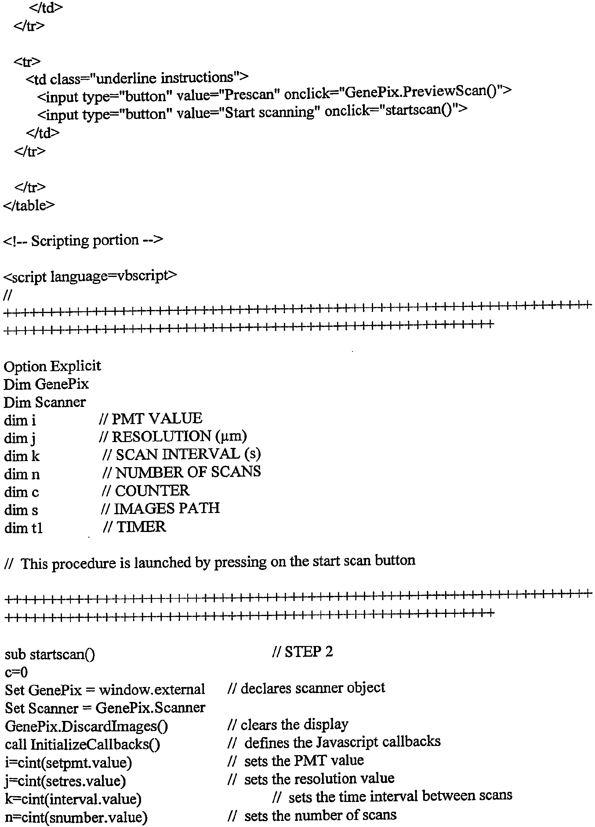


-
Figure 2 represents one embodiment of the disclosure in which parts of the two processes are present in the same compartment. The two processes are performed in the integrated system as long as the technical parts (necessary for having the specifications) are compatible with each other. The light source (1) is directed on the surface of the support (15) opposite to the surface in contact with the thermostatized carrier (12). The controller (11) includes a temperature controlling device. - In preferred embodiment, the excitation light (2) reaches the micro-array surface within an angle comprised between 45° and 135°, preferably between 60° and 120°, even more preferably between 80° and 100°. The light excitation is a direct excitation of the labeled target and do not use the internal reflexion of the light such as provided by the evanescent waves.
-
Figure 3 represents another embodiment of the disclosure in which the two processes are physically separated in two different parts of the apparatus. Some parts are moved: either the part of the machine and the support (15) is static or the support moves from one part to the other of the apparatus in order to be in the position to perform one of the two required processes or the target solution (13) moves either in block or in part, e.g. to be heated in one part and to react in an other part, or to perform the detection. The reading excitation light (2) is either directed and focused on the support (15) without crossing liquids (A) or through liquids (B) depending on the side of the support, which is illuminated. - In one embodiment, the excitation light (2) is directed and focused on the support without crossing liquids. In another embodiment, the excitation light (2) is directed and focused on the support through liquids.
-
Figure 4 represents still another embodiment of the disclosure in which the carrier (12) comprises a fluid mixing system. In a preferred embodiment, the reaction chamber (14) where the binding between target and capture molecules occur is in fluid communication with a reservoir (19). The carrier (12) and temperature regulating device (16) may be separated from the temperature controlling device (17). The controller (11) may also operate a device (18) to compress the reaction chamber (14). The reaction chamber (14) is compressed by the device (18) allowing the fluid to fill the reservoir (19). The succession of compression and depression of the chambers allow the mixing of the solution. The reading of the micro-array is preferably performed when the reaction chamber is compressed. Two readings are made with the same compression. - In another embodiment, the liquid present in the reaction chamber is moved to the reservoir (19) by insertion of a glass slide in the reaction chamber (14).
- In another embodiment, during the reading of micro-array, the thickness of liquid in the reaction chamber is comprised between 0.1 and 500 µm and preferably between 10 and 100 µm.
- In another embodiment, during the reading of micro-array, the thickness of liquid in the reaction chamber as compared to the reservoir is smaller by a factor of between 2 and 100.
- In a particular embodiment, the apparatus performs a real-time quantification on micro-array of multiple target molecules (13) being labeled, and comprises,
- a support (15) having fixed upon its surface a micro-array, comprising at least one capture molecules (20) being immobilized in specifically localized areas (21) of said support, which is in fluid communication with said labeled target molecule (13),
- optionally a carrier (12) for holding said support,
- a electronic temperature control system (16-17);
- an excitation light source (1),
- an optical system for directing and focusing an excitation light (2) from said excitation light source (1) directly on said support, wherein the excitation light reaches the micro-array surface within an angle comprised between 45 and 135°.
- a detector (10) for measuring the electromagnetic light emission (7) from the bound target molecule in response to said excitation light in the presence of the solution containing the target molecule wherein the surface of emission for a localized area is comprised between about 0.1 µm2 and about 10 mm2,
- wherein the different parts are integrated into the same apparatus in order to read the light emission of the array while keeping the solution in the target molecules in fluid communication with the support at a regulated temperature.
- The Diaglass slides (Eppendorf, Hamburg, Germany) are functionalized for the presence of aldehydes according to the method described in patent application
WO02/18288 - The capture probes are designed to be specific of DNA binding site of transcriptional factors and have the following sequences:
- TELK1 (SEQ ID NO: 1):
- 5'Amine-GATGTCCTAATATGGACATCCTGTGT-3'
- TAP1 (SEQ ID NO: 2):
- 5'Amine-CGCTTGATGAGTCAGCCGGAACGG-3'
- TSTAT2 (SEQ ID NO: 3):
- 5'Amine-GATTTCTGGGAAACTGAAACTACC-3'
- TNFAT (SEQ ID NO: 4):
- 5'Amine-TATGAAACAAATTTTCCTCTTTGGGCG-3'
- TMYC (SEQ ID NO: 5):
- 5'Amine-TCGGAGGCCACGTGGGCGCTG-3'
- TCREB (SEQ ID NO: 6):
- 5'Amine- CTAGCTCTCTGACGTCAGGCAAT-3'
- The labeled probes are designed to be complementary of the immobilized capture probes and have the following sequences:
- PELK1 (SEQ ID NO: 7):
- 5'-Cy3-ACACAGGATGTCCATATTAGGACATC-3'
- PAP1 (SEQ ID NO: 8):
- 5'-Cy3-CCGTTCCGGCTGACTCATCAAGCG-3'
- PSTAT2 (SEQ ID NO: 9):
- 5'-Cy3-GGTAGTTTCAGTT'TCCCAGAAATC-3'
- PNFAT (SEQ ID NO: 10):
- 5'-Cy3-CGCCCAAAGAGGAA.AATTTGTTTCATA-3'
- PMYC (SEQ ID NO: 11):
- 5'-Cy3-CAGCGCCCACGTGGCCTCCGA-3'
- PCREB (SEQ ID NO: 12):
- 5'-Cy3-ATTGCCTGACGTCAGAGAGCTAG-3'
- Six polynucleotides probes labeled with Cy3 at 5' end (PELK1, PAP1, PSTAT2, PNFAT,
- PMYC and PCREB) have been hybridized at a concentration of 0.3 nM each in 0.2 M phosphate buffer pH 7.4 in a total volume of 25 µl on complementary capture molecules (TELK1, TAP1, TSTAT2, TNFAT, TMYC and TCREB) of a micro-array. A negative control (CTL-),
- non-specific of the capture molecules of the micro-array is simultaneously incubated. The solution (25 microliter) was loaded on the micro-array framed by an hybridisation chamber ,of 9 x 9 mm and a thickness of 310 micrometers sealed with a flat coverslip and incubated at 55°C without agitation in the thermostatized part of the apparatus which comprises a temperature control system with a precision of 1°C. The thickness of the liquid above the micro-array was 310 micrometers. Every 3 min, the slide was transferred from the incubation part of the apparatus to the scanning part , put upside down in a scanner and scanned at excitation wavelength 532. At the end of the scanning, the slide was put again in the thermostatized apparatus until the next scan. The slide was scanned at
time figure 5 . - The capture probe immobilization was conducted as described in example 1. One polynucleotide probe labeled with Cy3 at 5' end PAP1 (SEQ ID NO: 8) has been hybridized at three different concentrations (0.8 and 0.2 nM) in 0.2 M phosphate buffer pH 7.4 in a total volume of 25 µl on three separate micro-arrays comprising complementary capture molecule TAP1 (SEQ ID NO: 2). The solution was loaded on the micro-array and the detection was performed as explained in example 1. The slide was incubated at 55°C and scanned at
time Figure 6 . - The capture probe immobilization was conducted as described in example 1. One polynucleotide probe labeled with Cy3 at 5' end PAP 1 (SEQ ID NO: 8) have been simultaneously hybridized on two capture molecules of a micro-array, one being a perfect match (TAP1 (SEQ ID NO: 2)) and one mutated (TAP1M (SEQ ID NO: 13)).
- TAP1M (SEQ ID NO: 13):
- 5'Amine-CGCTTGATTGCTTGGCCGGAACGG-3'
- The mutated bases as compared to the
wild type TAP 1 sequence are underlined. - The labeled polynucleotide was incubated at a concentration of 0.3 nM in 0.2 M phosphate buffer pH 7.4 in a total volume of 25 µl. The solution was loaded on the micro-array framed by an hybridisation chamber, sealed with a coverslip. The thickness of the liquid above the micro-array was 310 micrometers. The slide was incubated at 55°C by sealing a peltier element on its back and the slide carrying the peltier is placed upside down in the scanner during the whole experiment. After 60 min at 55°C, the temperature of the peltier was decreased down to 23°C and then increased up to 55°C for 3 min. The temperature was then increased up to 62°C for 4 min, then up to 75°C for 6 min and up to 85°C for 1 min. The micro-array was scanned every 32 sec during the incubation in the same apparatus incorporating a scanner with an excitation wavelength 532. Results are presented in
Figure 7 . - The capture probe immobilization was conducted as described in example 1.
- The capture probes used in this experiment have the following sequences:
- TA (SEQ ID NO: 14):
- 5'Amine-GCTAACTGAGCACAGGAT-3'
- TA' (SEQ ID NO: 15):
- 5'Amine-TAACTGAGCACGGAT-3'
- TB (SEQ ID NO: 16):
- 5'Amine-GCAGTGGGTGACCGAG-3'
- TB' (SEQ ID NO: 17):
- 5'Amine-GCAGGGGTGACCGAGGA-3'
- TC (SEQ ID NO: 18):
- 5'Amine-CCCAGGACGCCCCTTTC-3'
- TC' (SEQ ID NO: 19):
- 5'Amine-CCCAAGACGCCCCTTTC-3'
- Nucleotide differences between the capture probes A, B, C and their counterpart A', B', C' are underlined. In TA' probe, there is a deletion of adenine (A) at
position 5 from 3' end as compared to TA probe. In TB', deletion of thymine (T) atposition 5 from the 5' end as compared to TB probe. In TC', there is a substitution (G->A) inposition 5 from the 5' end. - Each capture probe comprises a spacer at its 5' end as proposed in
WO0177372 - The labeled probes are designed to be complementary of the immobilized capture probes A, B, C and have the following sequences:
- PA (SEQ ID NO: 20):
- 5'-Cy3-ATCCTGTGCTCAGTTAGC -3'
- PB (SEQ ID NO: 21):
- 5'-Cy3-CTCGGTCACCCACTGC -3'
- PC (SEQ ID NO: 22):
- 5'-Cy3-GAAAGGGGCGTCCTGGG -3'
- Three polynucleotides probes (PA (SEQ ID NO: 20), PB (SEQ ID NO: 21), PC (SEQ ID NO: 22) labeled with Cy3 at 5' end, which are specific respectively of capture molecules A, B and C (TA (SEQ ID NO: 14), TB (SEQ ID NO: 16, TC (SEQ ID NO: 18), have been hybridized at a concentration of 0.3 nM in 0.2 M phosphate buffer pH 7.4 in a total volume of 25 µl on the same micro-array comprising also mutated capture molecule (TA' (SEQ ID NO: 15), TB' (SEQ ID NO: 17), TC' (SEQ ID NO: 19).
- The solution was loaded on the micro-array and processed as in example 3. Specific (on TA, TB, TC capture probes) and non-specific hybridization (on TA', TB', TC' capture probes) have been followed with time by scanning the micro-array at
time figure 8 . This result shows the effect of the probe on the specificity of hybridization : probe PC is the most discriminating, PB is also discriminating but less than PC and PA is non discriminating. Temperature (50°C and 65°C) has a clear effect on SNP detection. At 65°C, there is a good discrimination for probe PC while no discrimination was observed at 50°C. - The Diaglass slides (Eppendorf, Hamburg, Germany) were functionalized for the presence of aldehydes according to the method described in patent application
WO02/18288 - The antibodies were purchased from different providers as follows:
Mouse antibodies : A (Santa Cruz, N° SC-7972), B (Upstate, N° 05-454), C (BD, N° 612.169), D (Biosource, N° AHO0782), E (R&D, N° MAB869), F (Cell signaling, N° 9216), G (Santa Cruz, N° SC-7973), H (BD, N° 612.281), I (BD, N° 612.289).
Rabbit antibodies : A' (Sigma, N° M0800), B' (Santa Cruz, N° SC-535), C' (Santa Cruz, N° SC-728), D' (Santa Cruz, N° SC-7149), E' (R&D, N° AF8691), F' (R&D, N° AF869), G' (Biosource, N° 44 684 Z), H' (Santa Cruz, N° SC-7975-R). - A micro-array has been spotted with 9 different mouse antibodies (A-I) and 8 different rabbit antibodies (A'-H') at 2 concentrations (200µg/ml and 20µg/ml). Solutions were loaded on the micro-array and detection was performed as in example 3. Goat anti-rabbit antibody labeled with Cy3 (Jackson Immunoresearch, N° 111-165-003) diluted 1000X in PBS +
BSA 1% + Tween 0.5% was incubated on the micro-array for 30 min in a chamber in a final volume of 25 µl. On a second array, goat anti-mouse antibody labeled with Cy3 (Jackson Immunoresearch, N° 115-165-003) diluted 1000X was processed similarly. The incubation was made at 20°C in the same apparatus incorporating a scanner with the slide upside down. Specific and non-specific reactions were monitored online by scanning the micro-array every min until 20 min and then every 5 min until 30 min incubation.Figure 9 shows the online detection of a mouse antibody spotted at 200µg/ml (I, BD, N° 612.289).) and a rabbit antibody spotted at 200µg/ml (A', Sigma, N°M0800) with a goat anti-mouse antibody-Cy3 during 30 min. - 1 µl of total RNA (10 µg/µl) from rat liver (Ambion) was mixed with 2 µl oligo(dT)12-18 (0.5 µg/µl, Roche), 3.5 µl H2O, and 2 µl of a solution of 6 different synthetic well-defined poly(A+) RNAs. These latter served as internal standards to assist in quantification and estimation of experimental variation introduced during the subsequent steps of analysis. The 6 Internal standard RNA are present at different concentrations : IS 1= 10ng/ml, IS2= Ing/ml, IS3= 100pg/ml, IS4= 30pg/ml, IS5=10pg/ml, IS6=5pg/ml.
- After an incubation of 10 min at 70°C and 5 minutes on ice, 9 µl of reaction mix were added. Reaction mix consisted in 4 µl Reverse Transcription Buffer 5X (Gibco BRL), 1 µl RNAsin Ribonuclease Inhibitor (40 U/ml, Promega), and 2 µl of a 10X dNTP mix, made of dATP, dTTP, dGTP (5 mM each, Roche), dCTP (800 µM, Roche), and Cy3-dCTP (800 µM, NEN).
- After 5 min at room temperature, 1.5 µl SuperScript II (200 U/ml, Gibco BRL) was added and incubation was performed at 42°C for 90 min. Addition of SuperScript and incubation were repeated once. The mixture was then placed at 70°C for 15 min and 1 µl Ribonuclease H (2U/µl) was added for 20 minutes at 37°C. Finally, a 3-min denaturation step was performed at 95°C. After reverse transcription step, the RT product is purified from free dCTP-Cy3 on a G25 spin column (Pierce,#89849). The purified fluorescent cDNA, was kept at -20°C.
- 20 µl of purified and Cy3 labeled RT product was hybridized onto a DualChip rat hepato (Eppendorf, Hamburg, Germany) in
SSC 2X SDS 4% in a total volume of 25 µl. The solution was loaded on the micro-array and the detection was performed as in example 1. The slide was incubated for 22 hours at 65°C mixing at 1400 rpm in the incubation part of the apparatus. At the time of reading, the agitation was stopped and the slide was transferred to the scanning part of the apparatus, put upside down and scanned at excitation wavelength 532. - The slide was scanned at
time 2 min, 90 min, 200 min, 6 hours, 14 hours and 22 hours.Figure 10 presents the real-time hybridization ofIS 1 cDNA.
Claims (37)
- A method for real-time quantification of different target molecules on a micro-array comprising the steps of:placing, in a reaction chamber (14), a support (15) having fixed upon its surface a micro-array comprising at least 5 capture molecules (20) each being immobilized in specifically localized areas (21) of said support,introducing a solution containing labelled target molecules (13) into the reaction chamber (14),incubating said labelled target molecules (13) under conditions allowing a specific binding between said targets (13) and their corresponding capture molecules (20),directing an excitation light (2) from a light source (1) on the surface of the support wherein the excitation light reaches the micro-array surface within an angle which does not induce internal reflection of light as provided by evanescence wave, so that the excitation light is directed directly on the surface of the support,measuring the light emission (7) from the bound target molecules in response to said excitation light (2) in the presence of the solution containing the labelled target molecules (13), wherein the surface of emission for a localized area is comprised between about 0.1 µm2 and about 10 mm2 and wherein each of the at least 4 localized areas is monitored with time with at least two measurements being done per localized area (21), andprocessing and storing the values of the different measurements and quantifying at least 4 different target molecules present in the solution using at least one measurement value for each said target, wherein calculation of the concentration of the labelled target molecules present in solution is derived from calculation of a kinetic coefficient of a signal appearance with time in the localized area to which an individual target binds in a specific manner.
- The method of claim 1, wherein the incubation system provides conditions so that the thickness of the solution being in contact with the micro-array is constant above all the localized areas.
- The method of claim 1, wherein the difference of thickness of the liquid above two localized areas is less than 100 micrometers preferably less than 10 micrometers and even less than 1 micrometer.
- The method of claim 1, wherein the thickness of the solution being in contact with the micro-array is changed between two measurements.
- The method of claim 1, wherein the target molecules are labelled with a fluorescent dye, preferably cyanine 3.
- The method of claim 1, wherein the target molecules are selected from the group consisting of nucleic acids, homologous nucleotide sequences or proteins.
- The method of claim 6, wherein the proteins are selected from the group consisting of antibody, antigen, ligand, receptor.
- The method of claim 1, wherein the temperature during the binding reaction is held constant with a variation of the temperature of less than 5°C, preferably less than 1°C.
- The method of claim 1, wherein the measurement is performed between 1 min and 24 h.
- The method of claim 9, wherein the temperature is held constant during the calculation period preferably for at least 1 min during the calculation period, more preferably between 1 and 60 min during the calculation period.
- The method of claim 1, wherein the concentration of the target molecules in the detection solution is between about 0.0001 and about 1000 nM, preferably between about 0.001 and about 10 nM.
- The method of claim 1, wherein the support (15) contains a substrate on which are fixed the capture molecules, which is preferably glass.
- The method of claim 1, wherein the micro-array contains more than 20 different capture molecules and less than 1000.
- The method of claim 1, wherein the capture molecules are deposited by physical means on the substrate or are synthesized in situ on the substrate in predefined locations.
- The method of claim 1, wherein the capture molecules are present in defined locations on the substrate.
- The method of claim 1, wherein the surface of emission of the localized area for the detection of a target is comprised between 1 µm2 and 1 mm2.
- The method of claim 1, wherein the surface of the support bearing the capture molecules has a 3 dimensional structure.
- The method of claim 1, wherein the support bears several micro-arrays separated by physical boundaries.
- The method of claim 18, wherein the support has a multi-well format.
- The method of claim 1, wherein the calculation of the concentration of a target present in solution is derived from the first order kinetic coefficient of the signal taken from at least 3 values taken with time in the localized area to which the target binds specifically.
- The method of claim 1, wherein the solution containing the target molecules is submitted to temperature cycles having at least 2 and preferably 3 different temperatures between two or more measurements.
- The method of claim 21, wherein the temperature cycles and the reaction conditions are those which produce a PCR.
- A method for the determination of the optimal incubation conditions for hybridization of a target molecule, comprising the steps of:- placing, in a reaction chamber (14), a support (15) having fixed upon its surface a micro-array comprising at least 5 capture molecules (20) each being immobilized in specifically localized areas (21) of said support,- introducing a solution containing labelled target molecules (13) into the reaction chamber (14),- incubating said labelled target molecules (13) under conditions allowing a specific binding between said targets (13) and their corresponding capture molecules (20),- directing an excitation light (2) from a light source (1) on the surface of the support, wherein the excitation light reaches the micro-array surface within an angle which does not induce internal reflection of light as provided by evanescence wave, so that the excitation light is directed directly on the surface of the support,- measuring the light emission (7) from the bound target molecules in response to said excitation light (2) in the presence of the solution containing the labelled target molecules (13), wherein the surface of emission for a localized area is comprised between about 0.1 µm2 and about 10 mm2 and wherein each of the at least 5 localized areas is monitored with time with at least two measurements being done per localized area (21), and- processing and storing the values of the different measurements and quantifying at least 5 different target molecules present in the solution using at least one measurement value for each said target, wherein calculation of the concentration of the labelled target molecules present in solution is derived from calculation of a kinetic coefficient of a signal appearance with time in the localized area to which an individual target binds in a specific manner.
- A method for the determination of high binding efficiency of a target molecule on its specific capture molecule while having a very high discrimination of fixation with nucleotide sequences differing by at least one nucleotide from the target sequence comprising the steps of:- placing, in a reaction chamber (14), a support (15) having fixed upon its surface a micro-array comprising at least 5 capture molecules (20) each being immobilized in specifically localized areas (21) of said support,- introducing a solution containing labelled target molecules (13) into the reaction chamber (14),- incubating said labelled target molecules (13) under conditions allowing a specific binding between said targets (13) and their corresponding capture molecules (20),- directing an excitation light (2) from a light source (1) on the surface of the support, wherein the excitation light reaches the micro-array surface within an angle which does not induce internal reflection of light as provided by evanescence wave, so that the excitation light is directed directly on the surface of the support,- measuring the light emission (7) from the bound target molecules in response to said excitation light (2) in the presence of the solution containing the labelled target molecules (13), wherein the surface of emission for a localized area is comprised between about 0.1 µm2 and about 10 mm2 and wherein each of the at least 5 localized areas is monitored with time with at least two measurements being done per localized area (21), and- processing and storing the values of the different measurements and quantifying at least 5 different target molecules present in the solution using at least one measurement value for each said target,wherein the discrimination of the signal between the capture probe being specific and the capture probe having the mutation is higher than 5 and preferably higher than 10, wherein calculation of the concentration of the labelled target molecules present in solution is derived from calculation of a kinetic coefficient of a signal appearance with time in the localized area to which an individual target binds in a specific manner.
- The method of claim 24 for optimizing hybridization condition for SNP detection in a target sequence, or for optimizing hybridization and detection conditions of SNP in different targets sequences possibly present in the same solution.
- The method of claim 1, wherein more than 1000 target molecules present in a solution are quantified in the same assay.
- The method of claim 1, wherein between 1 and 1000 target molecules, preferably between 1 and 20, more preferably between 1 and 5 target molecules present in a solution are quantified in the same assay.
- The method of claim 1, wherein the measurement is performed on labelled target molecules (13) being in double stranded form.
- The method according to claim 1, wherein the targets to be detected are nucleotide molecules at concentration lower than 1 nM in the solution.
- The method according to claim 1, wherein the targets to be detected are antigen or antibodies at concentration lower than 1 µM in the solution.
- The method of claim 1 wherein the excitation light (2) is a laser beam directed and focused on the surface of the micro-array.
- The method of claim 1 wherein the excitation light (2) is directed and focused on the surface of the micro-array through the solution.
- The method of claim 1 wherein the excitation light is directed and focused on the surface of the array through the support.
- The method according to claim 1, wherein the surface of the array is scanned by the laser beam.
- The method according to claim 1, wherein the emitted light is detected as a confocal light and measure after amplification by a photomultiplier.
- A method for real-time quantification of different target molecules on a micro-array comprising the steps of:- placing, in a reaction chamber (14), a support (15) having fixed upon its surface a micro-array comprising at least 5 capture molecules (20) each being immobilized in specifically localized areas (21) of said support,- introducing a solution containing labelled target molecule(s) (13) into the reaction chamber (14),- incubating said labelled target molecule(s) (13) under conditions allowing a specific binding between said target(s) (13) and their corresponding capture molecules (20),- directing an excitation light (2) from a light source (1) on the surface of the support, wherein the excitation light reaches the micro-array surface within an angle which does not induce internal reflection of light as provided by evanescence wave, so that the excitation light is directed directly on the surface of the support,- measuring the light emission (7) from the bound target molecule(s) in response to said excitation light (2) in the presence of the solution containing the labelled target molecule(s) (13), wherein the surface of emission for a localized area is comprised between about 0.1 µm2 and about 10 mm2 and wherein each of the at least 5 localized areas is monitored with time with at least two measurements being done per localized area (21), and- processing and storing the values of the different measurements on at least 5 localized areas and quantifying the target molecule(s) present in the solution using at least one measurement value for each said target, wherein calculation of the concentration of the labelled target molecules present in solution is derived from calculation of a kinetic coefficient of a signal appearance with time in the localized area to which an individual target binds in a specific manner.
- The method according to claim 23, wherein the discrimination of the signal between the capture probe being specific and the capture probe having the mutation is higher than 5 and preferably higher than 10.
Priority Applications (1)
| Application Number | Priority Date | Filing Date | Title |
|---|---|---|---|
| EP05806579A EP1812594B1 (en) | 2004-11-18 | 2005-11-18 | Real-time quantification of multiple targets on a micro-array |
Applications Claiming Priority (4)
| Application Number | Priority Date | Filing Date | Title |
|---|---|---|---|
| EP04027435A EP1659183A1 (en) | 2004-11-18 | 2004-11-18 | Real-time quantification of multiple targets on a micro-array |
| US10/991,087 US8288128B2 (en) | 2004-11-18 | 2004-11-18 | Real-time quantification of multiple targets on a micro-array |
| EP05806579A EP1812594B1 (en) | 2004-11-18 | 2005-11-18 | Real-time quantification of multiple targets on a micro-array |
| PCT/EP2005/012382 WO2006053769A1 (en) | 2004-11-18 | 2005-11-18 | Real-time quantification of multiple targets on a micro-array |
Publications (2)
| Publication Number | Publication Date |
|---|---|
| EP1812594A1 EP1812594A1 (en) | 2007-08-01 |
| EP1812594B1 true EP1812594B1 (en) | 2013-01-09 |
Family
ID=35539286
Family Applications (3)
| Application Number | Title | Priority Date | Filing Date |
|---|---|---|---|
| EP10172182A Revoked EP2302072B1 (en) | 2004-11-18 | 2005-11-18 | Real time-PCR of targets on a micro-array |
| EP05813624A Not-in-force EP1704258B1 (en) | 2004-11-18 | 2005-11-18 | Real-time pcr of targets on a micro-array |
| EP05806579A Not-in-force EP1812594B1 (en) | 2004-11-18 | 2005-11-18 | Real-time quantification of multiple targets on a micro-array |
Family Applications Before (2)
| Application Number | Title | Priority Date | Filing Date |
|---|---|---|---|
| EP10172182A Revoked EP2302072B1 (en) | 2004-11-18 | 2005-11-18 | Real time-PCR of targets on a micro-array |
| EP05813624A Not-in-force EP1704258B1 (en) | 2004-11-18 | 2005-11-18 | Real-time pcr of targets on a micro-array |
Country Status (6)
| Country | Link |
|---|---|
| US (1) | US20090191618A1 (en) |
| EP (3) | EP2302072B1 (en) |
| JP (1) | JP5026978B2 (en) |
| AT (3) | ATE482288T1 (en) |
| DE (1) | DE602005023705D1 (en) |
| WO (2) | WO2006053770A1 (en) |
Families Citing this family (38)
| Publication number | Priority date | Publication date | Assignee | Title |
|---|---|---|---|---|
| US7829313B2 (en) | 2000-03-24 | 2010-11-09 | Eppendorf Array Technologies | Identification and quantification of a plurality of biological (micro)organisms or their components |
| US7875442B2 (en) | 2000-03-24 | 2011-01-25 | Eppendorf Array Technologies | Identification and quantification of a plurality of biological (micro)organisms or their components |
| CA2348042A1 (en) | 2001-06-04 | 2002-12-04 | Ann Huletsky | Sequences for detection and identification of methicillin-resistant staphylococcus aureus |
| US11834720B2 (en) | 2005-10-11 | 2023-12-05 | Geneohm Sciences, Inc. | Sequences for detection and identification of methicillin-resistant Staphylococcus aureus (MRSA) of MREJ types xi to xx |
| EP2041301B1 (en) * | 2006-05-17 | 2014-12-31 | Eppendorf Array Technologies SA | Identification and quantification of a plurality of biological (micro)organisms or their components |
| US9133504B2 (en) | 2006-06-05 | 2015-09-15 | California Institute Of Technology | Real time microarrays |
| US8637436B2 (en) | 2006-08-24 | 2014-01-28 | California Institute Of Technology | Integrated semiconductor bioarray |
| US11001881B2 (en) | 2006-08-24 | 2021-05-11 | California Institute Of Technology | Methods for detecting analytes |
| US8048626B2 (en) | 2006-07-28 | 2011-11-01 | California Institute Of Technology | Multiplex Q-PCR arrays |
| US11525156B2 (en) | 2006-07-28 | 2022-12-13 | California Institute Of Technology | Multiplex Q-PCR arrays |
| US11560588B2 (en) | 2006-08-24 | 2023-01-24 | California Institute Of Technology | Multiplex Q-PCR arrays |
| JP2008102117A (en) * | 2006-09-21 | 2008-05-01 | Fujifilm Corp | Surface plasmon enhanced fluorescence sensor and fluorescence detecting method |
| EP1946841A1 (en) * | 2006-12-22 | 2008-07-23 | Eppendorf Array Technologies SA | Device and/or method for the detection of amplified nucleotides sequences on micro-arrays |
| EP1935496A1 (en) * | 2006-12-22 | 2008-06-25 | Eppendorf Array Technologies SA | Device and/or method for the detection of amplified nucleotides sequences on micro-arrays |
| JP2009060859A (en) * | 2007-09-07 | 2009-03-26 | Sumitomo Bakelite Co Ltd | Method for detecting gene |
| JP2011508219A (en) * | 2007-12-19 | 2011-03-10 | シンギュレックス・インコーポレイテッド | Single molecule scanning analyzer and method of use thereof |
| EP2245467B1 (en) | 2008-02-05 | 2022-04-06 | Pocared Diagnostics Ltd. | System for conducting the identification of bacteria in biological samples |
| EP2107125A1 (en) | 2008-03-31 | 2009-10-07 | Eppendorf Array Technologies SA (EAT) | Real-time PCR of targets on a micro-array |
| US20100069253A1 (en) * | 2008-09-12 | 2010-03-18 | Gindilis Andrei L | Impedance Spectroscopy Measurement of DNA |
| EP2382324A1 (en) | 2008-12-30 | 2011-11-02 | STMicroelectronics S.r.l. | Method, microreactor and apparatus for carrying out real-time nucleic acid amplification |
| WO2010084381A1 (en) * | 2009-01-21 | 2010-07-29 | Eppendorf Ag | Detection and/or quantification method of target molecules on a solid support |
| EP2221605A1 (en) * | 2009-02-12 | 2010-08-25 | Koninklijke Philips Electronics N.V. | A wire grid sensor |
| US10288632B2 (en) | 2009-09-21 | 2019-05-14 | Pocared Diagnostics Ltd. | System for conducting the identification of bacteria in biological samples |
| EP2369325A1 (en) | 2010-03-12 | 2011-09-28 | Eppendorf Ag | Array analysis for online detection |
| EP2441520A1 (en) | 2010-10-12 | 2012-04-18 | Eppendorf AG | Real-time amplification and micro-array based detection of nucleic acid targets in a flow chip assay |
| AU2011342975B2 (en) | 2010-12-17 | 2015-04-23 | Bjs Ip Limited | Methods and systems for fast PCR heating |
| WO2013080432A1 (en) * | 2011-11-28 | 2013-06-06 | ソニー株式会社 | Chemical sensor, chemical sensor module, chemical substance detector, and chemical substance detection method |
| WO2013138685A1 (en) * | 2012-03-16 | 2013-09-19 | Life Technologies Corporation | Systems and methods for assessing of biological samples |
| EP2855019A1 (en) | 2012-05-24 | 2015-04-08 | BJS IP Limited | Clamp for fast pcr heating |
| US9708647B2 (en) | 2015-03-23 | 2017-07-18 | Insilixa, Inc. | Multiplexed analysis of nucleic acid hybridization thermodynamics using integrated arrays |
| US9499861B1 (en) | 2015-09-10 | 2016-11-22 | Insilixa, Inc. | Methods and systems for multiplex quantitative nucleic acid amplification |
| KR20170099738A (en) | 2016-02-23 | 2017-09-01 | 노을 주식회사 | Contact-type staining patch and manufacturing method thereof |
| US10371610B2 (en) | 2016-02-23 | 2019-08-06 | Noul Co., Ltd. | Contact-type patch, staining method using the same, and manufacturing method thereof |
| KR102478636B1 (en) * | 2016-02-23 | 2022-12-19 | 노을 주식회사 | Polymerase chain reaction patch, diagnostic method using the patch and device using the same |
| KR20170099787A (en) * | 2016-02-23 | 2017-09-01 | 노을 주식회사 | Labeling substance storing patch, tissue diagnostic method using the patch and device using the same |
| WO2017155858A1 (en) | 2016-03-07 | 2017-09-14 | Insilixa, Inc. | Nucleic acid sequence identification using solid-phase cyclic single base extension |
| JP2022525322A (en) | 2019-03-14 | 2022-05-12 | インシリクサ, インコーポレイテッド | Methods and systems for time-gate fluorescence-based detection |
| CN116515617B (en) * | 2023-07-03 | 2023-10-20 | 杭州杰毅生物技术有限公司 | Centrifugal PCR-fluorescence multi-target detection chip |
Citations (1)
| Publication number | Priority date | Publication date | Assignee | Title |
|---|---|---|---|---|
| WO1998028444A2 (en) * | 1996-12-23 | 1998-07-02 | The University Of Chicago | Customized oligonucleotide microchips as multiple biosensors |
Family Cites Families (30)
| Publication number | Priority date | Publication date | Assignee | Title |
|---|---|---|---|---|
| NL154598B (en) | 1970-11-10 | 1977-09-15 | Organon Nv | PROCEDURE FOR DETERMINING AND DETERMINING LOW MOLECULAR COMPOUNDS AND PROTEINS THAT CAN SPECIFICALLY BIND THESE COMPOUNDS AND TEST PACKAGING. |
| US3817837A (en) | 1971-05-14 | 1974-06-18 | Syva Corp | Enzyme amplification assay |
| US3939350A (en) | 1974-04-29 | 1976-02-17 | Board Of Trustees Of The Leland Stanford Junior University | Fluorescent immunoassay employing total reflection for activation |
| US3996345A (en) | 1974-08-12 | 1976-12-07 | Syva Company | Fluorescence quenching with immunological pairs in immunoassays |
| US4277437A (en) | 1978-04-05 | 1981-07-07 | Syva Company | Kit for carrying out chemically induced fluorescence immunoassay |
| US4275149A (en) | 1978-11-24 | 1981-06-23 | Syva Company | Macromolecular environment control in specific receptor assays |
| US4366241A (en) | 1980-08-07 | 1982-12-28 | Syva Company | Concentrating zone method in heterogeneous immunoassays |
| US4683195A (en) | 1986-01-30 | 1987-07-28 | Cetus Corporation | Process for amplifying, detecting, and/or-cloning nucleic acid sequences |
| US5143854A (en) | 1989-06-07 | 1992-09-01 | Affymax Technologies N.V. | Large scale photolithographic solid phase synthesis of polypeptides and receptor binding screening thereof |
| US5994056A (en) | 1991-05-02 | 1999-11-30 | Roche Molecular Systems, Inc. | Homogeneous methods for nucleic acid amplification and detection |
| JP2909216B2 (en) | 1994-04-29 | 1999-06-23 | パーキン‐エルマー コーポレイション | Real-time detection device for nucleic acid amplification products |
| WO1996034983A1 (en) | 1995-05-05 | 1996-11-07 | The Perkin-Elmer Corporation | Methods and reagents for combined pcr amplification and hybridization probing assay |
| JP2002515738A (en) | 1996-01-23 | 2002-05-28 | アフィメトリックス,インコーポレイティド | Nucleic acid analysis |
| US5716784A (en) | 1996-02-05 | 1998-02-10 | The Perkin-Elmer Corporation | Fluorescence detection assay for homogeneous PCR hybridization systems |
| US6333155B1 (en) | 1997-12-19 | 2001-12-25 | Affymetrix, Inc. | Exploiting genomics in the search for new drugs |
| US5952202A (en) | 1998-03-26 | 1999-09-14 | The Perkin Elmer Corporation | Methods using exogenous, internal controls and analogue blocks during nucleic acid amplification |
| US20020177135A1 (en) * | 1999-07-27 | 2002-11-28 | Doung Hau H. | Devices and methods for biochip multiplexing |
| DE19949735A1 (en) | 1999-10-15 | 2001-05-10 | Bruker Daltonik Gmbh | Processing of samples in solutions with a defined small wall contact area |
| US6316200B1 (en) * | 2000-06-08 | 2001-11-13 | Becton, Dickinson And Company | Probes and methods for detection of nucleic acids |
| AU6834700A (en) * | 1999-08-13 | 2001-03-13 | Zeptosens Ag | Device and method for determining multiple analytes |
| US7205104B2 (en) | 2000-03-24 | 2007-04-17 | Eppendorf Array Technologies Sa (Eat) | Identification of biological (micro) organisms by detection of their homologous nucleotide sequences on arrays |
| JP3963422B2 (en) * | 2000-08-03 | 2007-08-22 | 日鉄環境エンジニアリング株式会社 | Nucleic acid measurement method |
| EP1184349A1 (en) | 2000-09-01 | 2002-03-06 | A.S.B.L. Facultes Universitaires Notre-Dame De La Paix | Method for obtaining a surface activation of a solid support for building biochips microarrays |
| US6754414B2 (en) * | 2001-09-27 | 2004-06-22 | Bio-Rad Laboratories, Inc. | Imaging of microarrays using fiber optic exciter |
| MXPA04006861A (en) * | 2002-01-18 | 2005-06-20 | Univ Utah Res Found | Detection of single nucleotide polymorphisms using planar waveguides. |
| US7935500B2 (en) * | 2002-03-26 | 2011-05-03 | Massachusetts Institute Of Technology | Identifying calcineurin activators for treatment of schizophrenia |
| DE10315074A1 (en) * | 2003-04-02 | 2004-10-14 | Clondiag Chip Technologies Gmbh | Device for the duplication and detection of nucleic acids |
| JP4074829B2 (en) * | 2003-04-16 | 2008-04-16 | 大日本印刷株式会社 | Bio-microarray substrate and bio-microarray |
| US20060030036A1 (en) * | 2004-05-28 | 2006-02-09 | Victor Joseph | Chips for multiplex analyses |
| US20060088844A1 (en) * | 2004-10-22 | 2006-04-27 | Honeywell International Inc. | Real-time PCR microarray based on evanescent wave biosensor |
-
2005
- 2005-11-18 EP EP10172182A patent/EP2302072B1/en not_active Revoked
- 2005-11-18 WO PCT/EP2005/012383 patent/WO2006053770A1/en active Application Filing
- 2005-11-18 WO PCT/EP2005/012382 patent/WO2006053769A1/en active Application Filing
- 2005-11-18 DE DE602005023705T patent/DE602005023705D1/en active Active
- 2005-11-18 EP EP05813624A patent/EP1704258B1/en not_active Not-in-force
- 2005-11-18 AT AT05813624T patent/ATE482288T1/en not_active IP Right Cessation
- 2005-11-18 JP JP2007541801A patent/JP5026978B2/en not_active Expired - Fee Related
- 2005-11-18 AT AT10172182T patent/ATE549420T1/en active
- 2005-11-18 EP EP05806579A patent/EP1812594B1/en not_active Not-in-force
-
2006
- 2006-05-17 AT AT06114103T patent/ATE505560T1/en not_active IP Right Cessation
-
2007
- 2007-05-14 US US12/301,186 patent/US20090191618A1/en not_active Abandoned
Patent Citations (1)
| Publication number | Priority date | Publication date | Assignee | Title |
|---|---|---|---|---|
| WO1998028444A2 (en) * | 1996-12-23 | 1998-07-02 | The University Of Chicago | Customized oligonucleotide microchips as multiple biosensors |
Also Published As
| Publication number | Publication date |
|---|---|
| JP2009530589A (en) | 2009-08-27 |
| EP1812594A1 (en) | 2007-08-01 |
| JP5026978B2 (en) | 2012-09-19 |
| EP2302072B1 (en) | 2012-03-14 |
| WO2006053770A8 (en) | 2006-08-24 |
| US20090191618A1 (en) | 2009-07-30 |
| EP1704258A1 (en) | 2006-09-27 |
| ATE505560T1 (en) | 2011-04-15 |
| WO2006053770A1 (en) | 2006-05-26 |
| DE602005023705D1 (en) | 2010-11-04 |
| ATE549420T1 (en) | 2012-03-15 |
| ATE482288T1 (en) | 2010-10-15 |
| WO2006053769A1 (en) | 2006-05-26 |
| EP1704258B1 (en) | 2010-09-22 |
| EP2302072A1 (en) | 2011-03-30 |
Similar Documents
| Publication | Publication Date | Title |
|---|---|---|
| EP1812594B1 (en) | Real-time quantification of multiple targets on a micro-array | |
| EP1659183A1 (en) | Real-time quantification of multiple targets on a micro-array | |
| US8580499B2 (en) | Detection and/or quantification method of target molecules on a solid support | |
| EP2291538B1 (en) | Amplification of nucleic acids using temperature zones | |
| EP2041301B1 (en) | Identification and quantification of a plurality of biological (micro)organisms or their components | |
| EP2441520A1 (en) | Real-time amplification and micro-array based detection of nucleic acid targets in a flow chip assay | |
| US20120053068A1 (en) | Real-time pcr of targets on a micro-array | |
| EP1788096A1 (en) | Lid for PCR vessel comprising probes permitting PCR amplification and detection of the PCR product by hybridisation without opening the PCR vessel | |
| US7829313B2 (en) | Identification and quantification of a plurality of biological (micro)organisms or their components | |
| US8288128B2 (en) | Real-time quantification of multiple targets on a micro-array | |
| EP2180066A1 (en) | Single nucleotide polymorphism genotyping detection via the real-time invader assay microarray platform | |
| EP2107125A1 (en) | Real-time PCR of targets on a micro-array | |
| US7875442B2 (en) | Identification and quantification of a plurality of biological (micro)organisms or their components | |
| EP1935496A1 (en) | Device and/or method for the detection of amplified nucleotides sequences on micro-arrays | |
| WO2009156915A1 (en) | Detection of tapped aliquots of amplified nucleic acids | |
| WO2010084381A1 (en) | Detection and/or quantification method of target molecules on a solid support | |
| EP2035142B1 (en) | Lid for pcr vessel comprising probes permitting pcr amplification and detection of the pcr product by hybridisation without opening the pcr vessel | |
| EP1946841A1 (en) | Device and/or method for the detection of amplified nucleotides sequences on micro-arrays | |
| WO2009156916A2 (en) | Melting curve measurement during amplification | |
| US20100167955A1 (en) | Microarray including layer comprising dna molecule and method of manufacturing the same | |
| JP5258755B2 (en) | A reaction chamber for real-time PCR that includes a capture probe and allows detection of PCR products by hybridization without opening the PCR chamber |
Legal Events
| Date | Code | Title | Description |
|---|---|---|---|
| PUAI | Public reference made under article 153(3) epc to a published international application that has entered the european phase |
Free format text: ORIGINAL CODE: 0009012 |
|
| 17P | Request for examination filed |
Effective date: 20070504 |
|
| AK | Designated contracting states |
Kind code of ref document: A1 Designated state(s): AT BE BG CH CY CZ DE DK EE ES FI FR GB GR HU IE IS IT LI LT LU LV MC NL PL PT RO SE SI SK TR |
|
| 17Q | First examination report despatched |
Effective date: 20071128 |
|
| DAX | Request for extension of the european patent (deleted) | ||
| GRAJ | Information related to disapproval of communication of intention to grant by the applicant or resumption of examination proceedings by the epo deleted |
Free format text: ORIGINAL CODE: EPIDOSDIGR1 |
|
| GRAP | Despatch of communication of intention to grant a patent |
Free format text: ORIGINAL CODE: EPIDOSNIGR1 |
|
| GRAP | Despatch of communication of intention to grant a patent |
Free format text: ORIGINAL CODE: EPIDOSNIGR1 |
|
| RAP1 | Party data changed (applicant data changed or rights of an application transferred) |
Owner name: EPPENDORF ARRAY TECHNOLOGIES |
|
| GRAS | Grant fee paid |
Free format text: ORIGINAL CODE: EPIDOSNIGR3 |
|
| GRAA | (expected) grant |
Free format text: ORIGINAL CODE: 0009210 |
|
| AK | Designated contracting states |
Kind code of ref document: B1 Designated state(s): AT BE BG CH CY CZ DE DK EE ES FI FR GB GR HU IE IS IT LI LT LU LV MC NL PL PT RO SE SI SK TR |
|
| REG | Reference to a national code |
Ref country code: GB Ref legal event code: FG4D |
|
| REG | Reference to a national code |
Ref country code: CH Ref legal event code: EP Ref country code: AT Ref legal event code: REF Ref document number: 592802 Country of ref document: AT Kind code of ref document: T Effective date: 20130115 |
|
| REG | Reference to a national code |
Ref country code: IE Ref legal event code: FG4D |
|
| REG | Reference to a national code |
Ref country code: DE Ref legal event code: R096 Ref document number: 602005037856 Country of ref document: DE Effective date: 20130307 |
|
| PG25 | Lapsed in a contracting state [announced via postgrant information from national office to epo] |
Ref country code: SI Free format text: LAPSE BECAUSE OF FAILURE TO SUBMIT A TRANSLATION OF THE DESCRIPTION OR TO PAY THE FEE WITHIN THE PRESCRIBED TIME-LIMIT Effective date: 20130109 |
|
| REG | Reference to a national code |
Ref country code: NL Ref legal event code: VDEP Effective date: 20130109 |
|
| REG | Reference to a national code |
Ref country code: AT Ref legal event code: MK05 Ref document number: 592802 Country of ref document: AT Kind code of ref document: T Effective date: 20130109 |
|
| REG | Reference to a national code |
Ref country code: LT Ref legal event code: MG4D |
|
| PG25 | Lapsed in a contracting state [announced via postgrant information from national office to epo] |
Ref country code: CY Free format text: LAPSE BECAUSE OF FAILURE TO SUBMIT A TRANSLATION OF THE DESCRIPTION OR TO PAY THE FEE WITHIN THE PRESCRIBED TIME-LIMIT Effective date: 20130109 Ref country code: ES Free format text: LAPSE BECAUSE OF FAILURE TO SUBMIT A TRANSLATION OF THE DESCRIPTION OR TO PAY THE FEE WITHIN THE PRESCRIBED TIME-LIMIT Effective date: 20130420 Ref country code: LT Free format text: LAPSE BECAUSE OF FAILURE TO SUBMIT A TRANSLATION OF THE DESCRIPTION OR TO PAY THE FEE WITHIN THE PRESCRIBED TIME-LIMIT Effective date: 20130109 Ref country code: AT Free format text: LAPSE BECAUSE OF FAILURE TO SUBMIT A TRANSLATION OF THE DESCRIPTION OR TO PAY THE FEE WITHIN THE PRESCRIBED TIME-LIMIT Effective date: 20130109 Ref country code: SE Free format text: LAPSE BECAUSE OF FAILURE TO SUBMIT A TRANSLATION OF THE DESCRIPTION OR TO PAY THE FEE WITHIN THE PRESCRIBED TIME-LIMIT Effective date: 20130109 Ref country code: BE Free format text: LAPSE BECAUSE OF FAILURE TO SUBMIT A TRANSLATION OF THE DESCRIPTION OR TO PAY THE FEE WITHIN THE PRESCRIBED TIME-LIMIT Effective date: 20130109 Ref country code: BG Free format text: LAPSE BECAUSE OF FAILURE TO SUBMIT A TRANSLATION OF THE DESCRIPTION OR TO PAY THE FEE WITHIN THE PRESCRIBED TIME-LIMIT Effective date: 20130409 Ref country code: IS Free format text: LAPSE BECAUSE OF FAILURE TO SUBMIT A TRANSLATION OF THE DESCRIPTION OR TO PAY THE FEE WITHIN THE PRESCRIBED TIME-LIMIT Effective date: 20130509 |
|
| PG25 | Lapsed in a contracting state [announced via postgrant information from national office to epo] |
Ref country code: PT Free format text: LAPSE BECAUSE OF FAILURE TO SUBMIT A TRANSLATION OF THE DESCRIPTION OR TO PAY THE FEE WITHIN THE PRESCRIBED TIME-LIMIT Effective date: 20130509 Ref country code: FI Free format text: LAPSE BECAUSE OF FAILURE TO SUBMIT A TRANSLATION OF THE DESCRIPTION OR TO PAY THE FEE WITHIN THE PRESCRIBED TIME-LIMIT Effective date: 20130109 Ref country code: PL Free format text: LAPSE BECAUSE OF FAILURE TO SUBMIT A TRANSLATION OF THE DESCRIPTION OR TO PAY THE FEE WITHIN THE PRESCRIBED TIME-LIMIT Effective date: 20130109 Ref country code: LV Free format text: LAPSE BECAUSE OF FAILURE TO SUBMIT A TRANSLATION OF THE DESCRIPTION OR TO PAY THE FEE WITHIN THE PRESCRIBED TIME-LIMIT Effective date: 20130109 Ref country code: NL Free format text: LAPSE BECAUSE OF FAILURE TO SUBMIT A TRANSLATION OF THE DESCRIPTION OR TO PAY THE FEE WITHIN THE PRESCRIBED TIME-LIMIT Effective date: 20130109 Ref country code: GR Free format text: LAPSE BECAUSE OF FAILURE TO SUBMIT A TRANSLATION OF THE DESCRIPTION OR TO PAY THE FEE WITHIN THE PRESCRIBED TIME-LIMIT Effective date: 20130410 |
|
| PG25 | Lapsed in a contracting state [announced via postgrant information from national office to epo] |
Ref country code: SK Free format text: LAPSE BECAUSE OF FAILURE TO SUBMIT A TRANSLATION OF THE DESCRIPTION OR TO PAY THE FEE WITHIN THE PRESCRIBED TIME-LIMIT Effective date: 20130109 Ref country code: DK Free format text: LAPSE BECAUSE OF FAILURE TO SUBMIT A TRANSLATION OF THE DESCRIPTION OR TO PAY THE FEE WITHIN THE PRESCRIBED TIME-LIMIT Effective date: 20130109 Ref country code: EE Free format text: LAPSE BECAUSE OF FAILURE TO SUBMIT A TRANSLATION OF THE DESCRIPTION OR TO PAY THE FEE WITHIN THE PRESCRIBED TIME-LIMIT Effective date: 20130109 Ref country code: CZ Free format text: LAPSE BECAUSE OF FAILURE TO SUBMIT A TRANSLATION OF THE DESCRIPTION OR TO PAY THE FEE WITHIN THE PRESCRIBED TIME-LIMIT Effective date: 20130109 Ref country code: RO Free format text: LAPSE BECAUSE OF FAILURE TO SUBMIT A TRANSLATION OF THE DESCRIPTION OR TO PAY THE FEE WITHIN THE PRESCRIBED TIME-LIMIT Effective date: 20130109 |
|
| PLBE | No opposition filed within time limit |
Free format text: ORIGINAL CODE: 0009261 |
|
| STAA | Information on the status of an ep patent application or granted ep patent |
Free format text: STATUS: NO OPPOSITION FILED WITHIN TIME LIMIT |
|
| 26N | No opposition filed |
Effective date: 20131010 |
|
| REG | Reference to a national code |
Ref country code: DE Ref legal event code: R097 Ref document number: 602005037856 Country of ref document: DE Effective date: 20131010 |
|
| REG | Reference to a national code |
Ref country code: CH Ref legal event code: PL |
|
| PG25 | Lapsed in a contracting state [announced via postgrant information from national office to epo] |
Ref country code: CH Free format text: LAPSE BECAUSE OF NON-PAYMENT OF DUE FEES Effective date: 20131130 Ref country code: LI Free format text: LAPSE BECAUSE OF NON-PAYMENT OF DUE FEES Effective date: 20131130 Ref country code: MC Free format text: LAPSE BECAUSE OF FAILURE TO SUBMIT A TRANSLATION OF THE DESCRIPTION OR TO PAY THE FEE WITHIN THE PRESCRIBED TIME-LIMIT Effective date: 20130109 |
|
| REG | Reference to a national code |
Ref country code: IE Ref legal event code: MM4A |
|
| PG25 | Lapsed in a contracting state [announced via postgrant information from national office to epo] |
Ref country code: IE Free format text: LAPSE BECAUSE OF NON-PAYMENT OF DUE FEES Effective date: 20131118 |
|
| PG25 | Lapsed in a contracting state [announced via postgrant information from national office to epo] |
Ref country code: TR Free format text: LAPSE BECAUSE OF FAILURE TO SUBMIT A TRANSLATION OF THE DESCRIPTION OR TO PAY THE FEE WITHIN THE PRESCRIBED TIME-LIMIT Effective date: 20130109 |
|
| PG25 | Lapsed in a contracting state [announced via postgrant information from national office to epo] |
Ref country code: LU Free format text: LAPSE BECAUSE OF NON-PAYMENT OF DUE FEES Effective date: 20131118 Ref country code: HU Free format text: LAPSE BECAUSE OF FAILURE TO SUBMIT A TRANSLATION OF THE DESCRIPTION OR TO PAY THE FEE WITHIN THE PRESCRIBED TIME-LIMIT; INVALID AB INITIO Effective date: 20051118 |
|
| REG | Reference to a national code |
Ref country code: FR Ref legal event code: PLFP Year of fee payment: 11 |
|
| REG | Reference to a national code |
Ref country code: FR Ref legal event code: PLFP Year of fee payment: 12 |
|
| PGFP | Annual fee paid to national office [announced via postgrant information from national office to epo] |
Ref country code: DE Payment date: 20161121 Year of fee payment: 12 Ref country code: GB Payment date: 20161122 Year of fee payment: 12 Ref country code: FR Payment date: 20161118 Year of fee payment: 12 |
|
| PGFP | Annual fee paid to national office [announced via postgrant information from national office to epo] |
Ref country code: IT Payment date: 20161123 Year of fee payment: 12 |
|
| REG | Reference to a national code |
Ref country code: DE Ref legal event code: R119 Ref document number: 602005037856 Country of ref document: DE |
|
| GBPC | Gb: european patent ceased through non-payment of renewal fee |
Effective date: 20171118 |
|
| REG | Reference to a national code |
Ref country code: FR Ref legal event code: ST Effective date: 20180731 |
|
| PG25 | Lapsed in a contracting state [announced via postgrant information from national office to epo] |
Ref country code: DE Free format text: LAPSE BECAUSE OF NON-PAYMENT OF DUE FEES Effective date: 20180602 Ref country code: IT Free format text: LAPSE BECAUSE OF NON-PAYMENT OF DUE FEES Effective date: 20171118 Ref country code: FR Free format text: LAPSE BECAUSE OF NON-PAYMENT OF DUE FEES Effective date: 20171130 |
|
| PG25 | Lapsed in a contracting state [announced via postgrant information from national office to epo] |
Ref country code: GB Free format text: LAPSE BECAUSE OF NON-PAYMENT OF DUE FEES Effective date: 20171118 |