EP1811247A2 - Verfahren zur Montage eines Wärmepumpenmoduls - Google Patents
Verfahren zur Montage eines Wärmepumpenmoduls Download PDFInfo
- Publication number
- EP1811247A2 EP1811247A2 EP07000642A EP07000642A EP1811247A2 EP 1811247 A2 EP1811247 A2 EP 1811247A2 EP 07000642 A EP07000642 A EP 07000642A EP 07000642 A EP07000642 A EP 07000642A EP 1811247 A2 EP1811247 A2 EP 1811247A2
- Authority
- EP
- European Patent Office
- Prior art keywords
- heat pump
- pump module
- vacuum furnace
- evacuated
- temperature
- Prior art date
- Legal status (The legal status is an assumption and is not a legal conclusion. Google has not performed a legal analysis and makes no representation as to the accuracy of the status listed.)
- Granted
Links
- 238000000034 method Methods 0.000 title claims description 32
- XKRFYHLGVUSROY-UHFFFAOYSA-N Argon Chemical compound [Ar] XKRFYHLGVUSROY-UHFFFAOYSA-N 0.000 claims description 10
- 239000010457 zeolite Substances 0.000 claims description 9
- 239000003463 adsorbent Substances 0.000 claims description 8
- 238000010438 heat treatment Methods 0.000 claims description 8
- 229910052756 noble gas Inorganic materials 0.000 claims description 8
- XLYOFNOQVPJJNP-UHFFFAOYSA-N water Substances O XLYOFNOQVPJJNP-UHFFFAOYSA-N 0.000 claims description 8
- 229910052786 argon Inorganic materials 0.000 claims description 5
- 239000003507 refrigerant Substances 0.000 claims description 5
- 239000001307 helium Substances 0.000 claims description 4
- 229910052734 helium Inorganic materials 0.000 claims description 4
- SWQJXJOGLNCZEY-UHFFFAOYSA-N helium atom Chemical compound [He] SWQJXJOGLNCZEY-UHFFFAOYSA-N 0.000 claims description 4
- 238000002844 melting Methods 0.000 claims description 4
- 230000008018 melting Effects 0.000 claims description 4
- 230000001143 conditioned effect Effects 0.000 claims description 3
- 238000003466 welding Methods 0.000 claims description 3
- 230000005484 gravity Effects 0.000 claims description 2
- 238000003825 pressing Methods 0.000 claims description 2
- 238000004140 cleaning Methods 0.000 claims 1
- 239000011261 inert gas Substances 0.000 abstract description 2
- 239000006096 absorbing agent Substances 0.000 abstract 2
- 239000000428 dust Substances 0.000 abstract 1
- 239000007789 gas Substances 0.000 description 10
- 238000001816 cooling Methods 0.000 description 9
- 229910021536 Zeolite Inorganic materials 0.000 description 8
- HNPSIPDUKPIQMN-UHFFFAOYSA-N dioxosilane;oxo(oxoalumanyloxy)alumane Chemical compound O=[Si]=O.O=[Al]O[Al]=O HNPSIPDUKPIQMN-UHFFFAOYSA-N 0.000 description 8
- 239000003570 air Substances 0.000 description 6
- 229910000679 solder Inorganic materials 0.000 description 6
- IJGRMHOSHXDMSA-UHFFFAOYSA-N Atomic nitrogen Chemical compound N#N IJGRMHOSHXDMSA-UHFFFAOYSA-N 0.000 description 4
- 230000015572 biosynthetic process Effects 0.000 description 4
- 239000000126 substance Substances 0.000 description 4
- 230000001419 dependent effect Effects 0.000 description 3
- 230000007613 environmental effect Effects 0.000 description 3
- 239000000155 melt Substances 0.000 description 3
- UFGZSIPAQKLCGR-UHFFFAOYSA-N chromium carbide Chemical compound [Cr]#C[Cr]C#[Cr] UFGZSIPAQKLCGR-UHFFFAOYSA-N 0.000 description 2
- 230000003750 conditioning effect Effects 0.000 description 2
- 239000000463 material Substances 0.000 description 2
- 229910052751 metal Inorganic materials 0.000 description 2
- 239000002184 metal Substances 0.000 description 2
- 229910052757 nitrogen Inorganic materials 0.000 description 2
- 229910003470 tongbaite Inorganic materials 0.000 description 2
- 239000002250 absorbent Substances 0.000 description 1
- 230000002745 absorbent Effects 0.000 description 1
- 239000012080 ambient air Substances 0.000 description 1
- 238000005452 bending Methods 0.000 description 1
- 239000003086 colorant Substances 0.000 description 1
- 238000011109 contamination Methods 0.000 description 1
- 239000000112 cooling gas Substances 0.000 description 1
- 238000005260 corrosion Methods 0.000 description 1
- 230000007797 corrosion Effects 0.000 description 1
- 238000005520 cutting process Methods 0.000 description 1
- 239000012535 impurity Substances 0.000 description 1
- 150000002739 metals Chemical class 0.000 description 1
- 150000002835 noble gases Chemical class 0.000 description 1
- 238000005086 pumping Methods 0.000 description 1
- 229920006395 saturated elastomer Polymers 0.000 description 1
- 239000002904 solvent Substances 0.000 description 1
- 238000005494 tarnishing Methods 0.000 description 1
- 238000005496 tempering Methods 0.000 description 1
- 238000003856 thermoforming Methods 0.000 description 1
- 230000001960 triggered effect Effects 0.000 description 1
- 238000009423 ventilation Methods 0.000 description 1
Images

Classifications
-
- F—MECHANICAL ENGINEERING; LIGHTING; HEATING; WEAPONS; BLASTING
- F25—REFRIGERATION OR COOLING; COMBINED HEATING AND REFRIGERATION SYSTEMS; HEAT PUMP SYSTEMS; MANUFACTURE OR STORAGE OF ICE; LIQUEFACTION SOLIDIFICATION OF GASES
- F25B—REFRIGERATION MACHINES, PLANTS OR SYSTEMS; COMBINED HEATING AND REFRIGERATION SYSTEMS; HEAT PUMP SYSTEMS
- F25B17/00—Sorption machines, plants or systems, operating intermittently, e.g. absorption or adsorption type
- F25B17/08—Sorption machines, plants or systems, operating intermittently, e.g. absorption or adsorption type the absorbent or adsorbent being a solid, e.g. salt
-
- Y—GENERAL TAGGING OF NEW TECHNOLOGICAL DEVELOPMENTS; GENERAL TAGGING OF CROSS-SECTIONAL TECHNOLOGIES SPANNING OVER SEVERAL SECTIONS OF THE IPC; TECHNICAL SUBJECTS COVERED BY FORMER USPC CROSS-REFERENCE ART COLLECTIONS [XRACs] AND DIGESTS
- Y02—TECHNOLOGIES OR APPLICATIONS FOR MITIGATION OR ADAPTATION AGAINST CLIMATE CHANGE
- Y02A—TECHNOLOGIES FOR ADAPTATION TO CLIMATE CHANGE
- Y02A30/00—Adapting or protecting infrastructure or their operation
- Y02A30/27—Relating to heating, ventilation or air conditioning [HVAC] technologies
-
- Y—GENERAL TAGGING OF NEW TECHNOLOGICAL DEVELOPMENTS; GENERAL TAGGING OF CROSS-SECTIONAL TECHNOLOGIES SPANNING OVER SEVERAL SECTIONS OF THE IPC; TECHNICAL SUBJECTS COVERED BY FORMER USPC CROSS-REFERENCE ART COLLECTIONS [XRACs] AND DIGESTS
- Y02—TECHNOLOGIES OR APPLICATIONS FOR MITIGATION OR ADAPTATION AGAINST CLIMATE CHANGE
- Y02B—CLIMATE CHANGE MITIGATION TECHNOLOGIES RELATED TO BUILDINGS, e.g. HOUSING, HOUSE APPLIANCES OR RELATED END-USER APPLICATIONS
- Y02B30/00—Energy efficient heating, ventilation or air conditioning [HVAC]
- Y02B30/62—Absorption based systems
Definitions
- the invention relates to a method for mounting a heat pump module.
- thermodynamic process energy from an environmental heat source is used in a thermodynamic process for heating purposes. It is possible to use environmental heat sources whose temperature level is well below the target temperature of the room to be heated or the water to be heated.
- zeolite heat pumps in a container in which there is a strong negative pressure, a refrigerant is vaporized by means of environmental heat and taken up by a zeolite, which heats up as a result. If the zeolite is saturated with the refrigerant, the refrigerant must be expelled again by supplying heat. The vaporous refrigerant is cooled on a condenser. The recovered heat is transferred to a heating circuit.
- the heating circuit can be used both for the generation of room heat and for dhw heating.
- the efficiency of the heat pump process depends heavily on the fact that no foreign gases have a negative impact on the process. On the one hand, it must be avoided that ambient air gets into the heat pump module. On the other hand, it must be prevented that when storing the zeolite in the heat pump module, the zeolite with foreign gases loaded. Such foreign gases that would be driven out of the zeolite during the heat pumping process significantly affected the process. Further, the evaporator / condenser, Sorber Knoxleyer and the housing should contain no foreign substances. For example, an oil that originates from thermoforming, cutting or bending processes or solvents could enter the zeolite in vapor form, which reduced its process capability. Other foreign substances to avoid are residues of welding processes or tarnish (thin oxide layers).
- Object of the present invention is therefore to provide a method for mounting a heat pump module, which prevents the presence of foreign substances in the heat pump module.
- the vacuum furnace is first evacuated in the cold state and heated only after falling below a threshold value, preferably a predetermined pressure or a predetermined evacuation time. As a result, tarnishing or scaling of the components is avoided.
- the pressure in the vacuum furnace is reduced to a value of less than 10 -4 mbar and the temperature is heated to a range between 1000 ° C and 1300 ° C.
- a predetermined temperature profile should be maintained in order to achieve a homogeneous material heating on the one hand and to avoid material damage on the other hand. If the oven temperature is heated to a predetermined temperature with a predetermined course, tempering colors are caused by the reduction removed the oxide layers and effectively removes impurities.
- the components should be stored deformation-proof, preferably in contoured forms. This avoids, for example, that metals deform due to gravity in the soft state.
- the cooling should also take place with a predetermined temperature profile in order to avoid chromium carbide formation. This preserves the corrosion resistance.
- noble gases or nitrogen can be used.
- the ventilation of the vacuum furnace may only be carried out below a temperature of 100 ° C in order to avoid a restart of the metal surfaces. After going through the previously described steps, the components must be packaged in such a way as to prevent re-contamination.
- the heat pump module is heated in an evacuated vacuum oven, whereby foreign gases can be removed from the adsorbent.
- the container is evacuated after assembly at a comparatively low temperature, wherein the pressure should be less than 10 -3 mbar.
- the temperature is slowly raised in the vacuum oven to a predetermined temperature, the pressure must not rise above a predetermined value, otherwise it may lead to the formation of tarnish.
- the predetermined maximum temperature the temperature is maintained for a certain time at the predetermined setpoint temperature and the pressure in the container further reduced until a second predetermined pressure is reached.
- the heat pump module can be closed gas-tight according to claim 6 already in the evacuated vacuum oven.
- the vacuum furnace is subsequently cooled, preferably with the addition of argon. This will be the cooling process accelerated significantly, since the cooling in the evacuated oven otherwise runs extremely slowly. Alternatively, cooling by helium would also be possible.
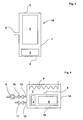
- a heat pump module 15 This consists of a module casing 1 with connecting flange 6, also a cover 2 and a bottom 3, which together form the module container. Furthermore, the heat pump module 15 has an evaporator / condenser 4 and a sorber 5, which consists of a fin heat exchanger and an adsorbent.
- components are cleaned in a first step in an ultrasonic bath.
- the heat exchanger of the sorber 5 and the evaporator / condenser 4 are cleaned in a vacuum oven 7.
- the vacuum furnace 7 has a heater 8, an oven door 14, a discharge pipe 13 and a supply pipe 12.
- the discharge pipe 13 and the supply pipe 12 are respectively closed by a valve 10, 13.
- a vacuum pump 9 is connected to the discharge line 13.
- the heat exchanger of the sorber 5 and evaporator / condenser 4 are introduced into the interior of the vacuum furnace 7 according to FIG. Subsequently, the vacuum furnace 7 is evacuated in the cold state by means of the vacuum pump 9 with the valve 10 open. If a predetermined pressure falls below, the heater 8 is turned on and the temperature in the vacuum furnace 7 continuously increased with a fixed predetermined temperature profile. Throughout the heating process, the valve 10 is opened, and the vacuum pump 9 continuously evacuates the interior of the vacuum furnace 7. The vacuum furnace 7 is at a Pressure of less than 10 -4 mbar evacuated. The maximum temperature of the process is between 1000 ° C and 1300 ° C. If this temperature is reached, the vacuum oven 7 is held at this temperature for a predetermined time.
- the vacuum furnace 7 Only then is the vacuum furnace 7 cooled. Again, the vacuum furnace 7 must be cooled with a predetermined temperature profile. If the cooling process is too slow, chromium carbide formation can occur. To accelerate the cooling process, the interior of the vacuum furnace 7 can be cooled via the supply line 12 with nitrogen or a noble gas. The heated gas can then be removed via the discharge line 13 and the opened valve 10 again to be cooled in an external cooler again. The cooling gas thus remains in a cycle. The interior of the oven is cooled to a temperature below 100 ° C to prevent the formation of tarnish when opening the vacuum oven 7. After pressure equalization, the vacuum furnace 7 can be opened and the components 4, 5 can be removed. Thereafter, they should only be transported and stored under clean room conditions.
- the purified heat exchanger of the sorber 5 is filled with adsorbent and sealed in such a gas-permeable manner that, although the adsorbent can no longer escape, but gases can reach the absorbent and can be derived.
- the sorber 5, the evaporator / condenser 4, the jacket 1, the cover 2 and the bottom 3 are installed to form a heat pump module 15 according to FIG. It is important to ensure that the connections, for example, welds have a sufficiently good vacuum tightness. At an appropriate test stand, the entire heat pump module 15 is checked for leaks.
- the heat pump module 15 is positioned in the vacuum furnace 7 according to FIG.
- the connection flange 6 must be located at the highest point in the module and facing upwards.
- the vacuum furnace 7 will now evacuated.
- the temperature in the vacuum furnace is continuously increased after a predetermined temperature profile.
- the temperature is maintained for a certain period of time until the pressure has fallen back to 10 -4 mbar. In this process, the foreign gases can escape from the adsorbent.
- the foreign gases first pass from the adsorbent into the interior of the heat pump module 15 and from there via the connection flange 6 into the interior of the vacuum furnace 7, from where the gases are discharged via the discharge line 13 and the vacuum pump 9. If the adsorbent and the heat pump module 15 are sufficiently evacuated, then the vacuum furnace 7 can be cooled again. For this purpose, the vacuum furnace 7 is cooled with a noble gas, which is heavier than air, for example argon. The argon is passed into the vacuum furnace 7, there cools the components and is then passed back out of the vacuum furnace 7 for cooling. If the interior of the vacuum furnace 7 is sufficiently cooled, a pressure equalization is performed with the same inert gas.
- the connecting flange 6 must be located at the lowest point on the underside of the heat pump module 15 during the conditioning process. The air can then displace the lighter helium when removing the heat pump module 15 from the vacuum furnace 7 upwards.
- the heat pump module 15 is evacuated.
- a vacuum pump 9 is connected to the valve of the heat pump module 15, the valve is opened and the noble gas is sucked off.
- the heat pump module 15 is filled with degassed water. When filling, care must be taken that foreign substances can not get into the heat pump module 15 again via the filling line.
- the heat pump module 15 is already sealed in a vacuum oven 7 gas-tight.
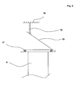
- a lid 16 is attached, which is held on a holding device 19 via a solder 18. If the module is adequately conditioned, the temperature in the vacuum furnace 7 is briefly increased. The solder seal 17 melts and the solder thread 18, which also melts, can no longer hold the cover 16, whereby the cover 16 covers the opening of the connection flange 6. As soon as the temperature in the vacuum furnace 7 is reduced, the solder seal 17 solidifies, whereby the heat pump module 15 is sealed gas-tight from its surroundings.
- the heat pump module 15 is cooled in the vacuum furnace 7, the cooling noble gas does not penetrate into the heat pump module 15.
- a gas-tight filling capillary which is connected to the cover 16 of the heat pump module, is connected by means of an evacuated filling line with the water reservoir.
- the filling capillary is pierced with a spike so that the degassed water passes through the filling line and the filling capillary into the interior of the heat pump module.
- the upper end of the filling capillary can be additionally closed with a spot weld.
- the flange can be designed in the form of a funnel and the cover in the form of a cone.
- the seal is shaped so that the cone in the rigid state of the seal rests only pointwise, continue the flange to Furnace space releases an opening and only when melting the seal, the cone falls into the hopper and is sealed by the solder. If the flange is located at the bottom of the container, then a spring mechanism for closing can be triggered thermally.
Landscapes
- Engineering & Computer Science (AREA)
- Physics & Mathematics (AREA)
- Mechanical Engineering (AREA)
- Thermal Sciences (AREA)
- General Engineering & Computer Science (AREA)
- Cooling Or The Like Of Semiconductors Or Solid State Devices (AREA)
- Vaporization, Distillation, Condensation, Sublimation, And Cold Traps (AREA)
- Solid-Sorbent Or Filter-Aiding Compositions (AREA)
- Sorption Type Refrigeration Machines (AREA)
Abstract
Description
- Die Erfindung bezieht sich auf ein Verfahren zur Montage eines Wärmepumpen-Moduls.
- Bei Wärmepumpen wird Energie von einer Umweltwärmequelle in einem thermodynamischen Prozess zu Heizzwecken verwendet. Hierbei ist es möglich, Umweltwärmequellen zu nutzen, deren Temperaturniveau deutlich unterhalb der Solltemperatur des zu beheizenden Raumes oder des zu beheizenden Wassers liegt.
- Bei Zeolith-Wärmepumpen wird in einem Behälter, in welchem ein starker Unterdruck herrscht, ein Kältemittel mittels Umweltwärme verdampft und von einem Zeolithen aufgenommen, der sich hierdurch erwärmt. Ist der Zeolith mit dem Kältemittel gesättigt, so muss durch Wärmezufuhr das Kältemittel wieder ausgetrieben werden. Das dampfförmige Kältemittel wird an einem Kondensator abgekühlt. Die jeweils gewonnene Wärme wird auf einen Heizkreislauf übertragen. Der Heizkreislauf kann sowohl zur Erzeugung von Raumwärme als auch von Brauchwasserbereitung verwendet werden.
- Die Effizienz des Wärmepumpenprozesses ist stark davon abhängig, dass keine Fremdgase den Prozess negativ beeinflussen. So ist einerseits zu vermeiden, dass Umgebungsluft in das Wärmepumpen-Modul gelangt. Andererseits muss verhindert werden, dass bei der Einlagerung des Zeolithen in das Wärmepumpen-Modul der Zeolith mit Fremdgasen beladen ist. Derartige Fremdgase, die während des Wärmepumpenprozesses aus dem Zeolithen getrieben würden, beeinflussten den Prozess erheblich. Ferner sollten der Verdampfer/Kondensator, Sorberwärmetauscher und das Gehäuse keine Fremdstoffe enthalten. So könnte beispielsweise ein Öl, das von Tiefzieh-, Schneid- oder Biegeprozessen stammt oder Lösemittel dampfförmig in den Zeolithen gelangen, was dessen Prozessfähigkeit reduzierte. Als weitere zu vermeidende Fremdstoffe kommen Rückstände von Schweißprozessen oder Anlauffarben (dünne Oxydschichten) in Frage.
- Aufgabe der vorliegenden Erfindung ist es daher, ein Verfahren zu Montage eines Wärmepumpenmoduls zu schaffen, welches die Anwesenheit von Fremdstoffen im Wärmepumpenmodul verhindert.
- Erfindungsgemäß wird dies zunächst gemäß den Merkmalen des Anspruchs 1 dadurch erreicht, dass Komponenten des Wärmepumpenmoduls in einem Vakuumofen bei hohen Temperaturen gereinigt und reduziert werden.
- Gemäß den Merkmalen des abhängigen Anspruchs 2 wird der Vakuumofen zunächst in kaltem Zustand evakuiert und erst nach Unterschreitung eines Schwellwertes, vorzugsweise eines vorgegebenen Drucks oder einer vorgegebenen Evakuierungszeit, erhitzt. Hierdurch wird ein Anlaufen oder eine Verzunderung der Komponenten vermieden.
- Als besonders vorteilhaft hat sich erwiesen, dass der Druck im Vakuumofen auf einen Wert von kleiner 10-4 mbar reduziert wird und die Temperatur auf einen Bereich zwischen 1000°C und 1300°C erhitzt wird. Bei der Erhitzung des Vakuumofens auf die vorgegebene Maximaltemperatur sollte ein vorgegebener Temperaturverlauf eingehalten werden, um einerseits eine homogene Materialerwärmung zu erreichen und andererseits Materialbeschädigungen zu vermeiden. Wird die Ofentemperatur mit vorgegebenem Verlauf auf eine vorgegebene Temperatur erhitzt, so werden Anlauffarben durch die Reduzierung der Oxydschichten entfernt und Verunreinigungen wirkungsvoll beseitigt. Die Komponenten sollten verformungssicher, vorzugsweise in konturierten Formen gelagert werden. Hierdurch wird beispielsweise vermieden, dass Metalle sich auf Grund der Schwerkraft im weichen Zustand verformen. Auch die Abkühlung sollte mit vorgegebenem Temperaturverlauf erfolgen, um Chromkarbitbildung zu vermeiden. Hierdurch bleibt die Korrosionsbeständigkeit erhalten. Zur schnelleren Abkühlung können Edelgase oder Stickstoff eingesetzt werden. Die Belüftung des Vakuumofens darf erst unterhalb einer Temperatur von 100°C erfolgen, um ein erneutes Anlaufen der Metalloberflächen zu vermeiden. Nach dem Durchfahren zuvor beschriebener Schritte müssen die Komponenten derartig verpackt werden, dass eine erneute Verunreinigung ausgeschlossen ist.
- Gemäß den Merkmalen des abhängigen Anspruchs 3 wird das Wärmepumpenmodul nach der Montage der Komponenten in einem evakuierten Vakuumofen erhitzt, wodurch Fremdgase aus dem Adsorbens entfernt werden können. Hierbei wird nach der Montage der Behälter bei vergleichsweise geringer Temperatur evakuiert, wobei der Druck kleiner 10-3 mbar sein sollte. Die Temperatur wird im Vakuumofen langsam auf eine vorgegebene Temperatur erhöht, wobei der Druck über einen vorgegebenen Wert nicht steigen darf, da es ansonsten zur Bildung von Anlauffarben kommen kann. Bei Erreichung der vorgegebenen Maximaltemperatur wird die Temperatur für eine bestimmte Zeit auf der vorgegebenen Solltemperatur gehalten und der Druck im Behälter weiter reduziert, bis ein zweiter vorgegebener Druck unterschritten ist.
- Das Wärmepumpenmodul kann gemäß Anspruch 6 bereits im evakuierten Vakuumofen gasdicht verschlossen werden.
- Gemäß den Merkmalen des abhängigen Anspruchs 7 wird der Vakuumofen anschließend abgekühlt, vorzugsweise unter Zugabe von Argon. Hierdurch wird der Abkühlprozess deutlich beschleunigt, da im evakuierten Ofen die Abkühlung ansonsten äußerst langsam abliefe. Alternativ wäre eine Kühlung mittels Helium ebenfalls möglich.
- Die Erfindung wird nun anhand der Figuren detailliert erläutert.
- Figur 1 zeigt die wesentlichen Bestandteile eines Wärmepumpenmoduls 15. Dieses besteht aus einem Modulmantel 1 mit Anschlussflansch 6, ferner einem Deckel 2 sowie einem Boden 3, welche zusammen den Modulbehälter bilden. Ferner verfügt das Wärmepumpenmodul 15 über einen Verdampfer/Kondensator 4 und einen Sorber 5, welcher aus einem Lamellenwärmetauscher und einem Adsorbens besteht.
- Sofern notwendig, werden Komponenten in einem ersten Verfahrensschritt in einem Ultraschallbad gereinigt.
- In einem weiteren Verfahrensschritt werden der Wärmetauscher des Sorbers 5 sowie der Verdampfer/Kondensator 4 in einem Vakuumofen 7 gereinigt. Der Vakuumofen 7 verfügt über eine Heizung 8, eine Ofentür 14, eine Abzugsleitung 13 und eine Zuführleitung 12. Die Abzugsleitung 13 und die Zuführleitung 12 werden jeweils von einem Ventil 10, 13 abgeschlossen. Ferner ist an die Abzugsleitung 13 eine Vakuumpumpe 9 angeschlossen.
- Der Wärmetauscher des Sorbers 5 und Verdampfer/Kondensator 4 werden gemäß Figur 2 in das Innere des Vakuumofens 7 eingebracht. Anschließend wird der Vakuumofen 7 im kalten Zustand mittels der Vakuumpumpe 9 bei geöffnetem Ventil 10 evakuiert. Ist ein vorgegebener Druck unterschritten, so wird die Heizung 8 eingeschaltet und die Temperatur im Vakuumofen 7 kontinuierlich mit fest vorgegebenem Temperaturverlauf gesteigert. Während des gesamten Aufheizprozesses ist das Ventil 10 geöffnet, und die Vakuumpumpe 9 evakuiert kontinuierlich das Innere des Vakuumofens 7. Der Vakuumofen 7 wird auf einen Druck von kleiner 10-4 mbar evakuiert. Die maximale Temperatur des Prozesses beträgt zwischen 1000°C und 1300°C. Ist diese Temperatur erreicht, so wird der Vakuumofen 7 für eine vorbestimmte Zeit auf dieser Temperatur gehalten. Erst anschließend wird der Vakuumofen 7 gekühlt. Auch hierbei muss der Vakuumofen 7 mit vorgegebenem Temperaturverlauf abgekühlt werden. Ist der Abkühlvorgang zu langsam, so kann es zu Chromkarbitbildung kommen. Zur Beschleunigung des Abkühlvorgangs kann der Innenraum des Vakuumofens 7 über die Zuführleitung 12 mit Stickstoff oder einem Edelgas gekühlt werden. Das aufgeheizte Gas kann anschließend über die Abführleitung 13 und das geöffnete Ventil 10 wieder entnommen werden, um in einem externen Kühler wieder abgekühlt zu werden. Das abkühlende Gas bleibt somit in einem Kreislauf. Das Ofeninnere wird auf eine Temperatur unterhalb 100°C abgekühlt, um beim Öffnen des Vakuumofens 7 die Bildung von Anlauffarben zu verhindern. Nach einem Druckausgleich kann der Vakuumofen 7 geöffnet werden und die Komponenten 4, 5 können entnommen werden. Danach sollten sie nur noch unter Sauberraumbedingungen transportiert und gelagert werden.
- Der gereinigte Wärmetauscher des Sorbers 5 wird mit Adorbens befüllt und derartig gasdurchlässig verschlossen, dass zwar das Adsorbens nicht mehr entweichen kann, Gase jedoch an das Absorbens gelangen und abgeleitet werden kann. Der Sorber 5, der Verdampfer/Kondensator 4, der Mantel 1, der Deckel 2 und der Boden 3 werden zu einem Wärmepumpenmodul 15 gemäß Figur 3 verbaut. Hierbei ist darauf zu achten, dass die Verbindungen, zum Beispiel Schweißnähte eine hinreichend gute Vakuumdichtheit aufweisen. An einem entsprechenden Prüfstand wird das komplette Wärmepumpenmodul 15 auf Dichtheit überprüft.
- Im Konditionierungs-Verfahrensschritt wird das Wärmepumpenmodul 15 in dem Vakuumofen 7 gemäß Figur 4 positioniert. Hierbei muss der Anschlussflansch 6 sich an der obersten Stelle im Modul befinden und nach oben weisen. Der Vakuumofen 7 wird nun evakuiert. Bei Unterschreiten eines vorgegebenen Druckes wird die Temperatur im Vakuumofen kontinuierlich nach einem vorgegebenen Temperaturverlauf erhöht. Bei einer Temperatur zwischen 320°C und 600°C (je nach eingesetztem Zeolith) wird die Temperatur über einen gewissen Zeitraum beibehalten bis der Druck wieder auf 10-4 mbar gesunken ist. Bei diesem Prozess können die Fremdgase aus dem Adsorbens entweichen. Die Fremdgase gelangen zunächst aus dem Adsorbens in den Innenraum des Wärmepumpenmoduls 15 und von dort über den Anschlussflansch 6 in den Innenraum des Vakuumofens 7, von wo aus die Gase über die Abführleitung 13 und die Vakuumpumpe 9 abgeführt werden. Ist der Adsorbens und das Wärmepumpenmodul 15 ausreichend evakuiert, so kann der Vakuumofen 7 wieder abgekühlt werden. Hierzu wird der Vakuumofen 7 mit einem Edelgas, welches schwerer als Luft ist, z.B. Argon gekühlt. Das Argon wird in den Vakuumofen 7 geleitet, kühlt dort die Komponenten und wird anschließend wieder aus dem Vakuumofen 7 zur Kühlung geleitet. Ist das Innere des Vakuumofens 7 ausreichend abgekühlt, so wird ein Druckausgleich mit dem gleichen Edelgas vorgenommen. Wird die Tür 14 des Vakuumofens 7 geöffnet, so kann keine Luft in das Wärmepumpenmodul 15 eindringen, da die Luft das schwerere Argon nicht nach unten verdrängen kann. Das Wärmepumpenmodul 15 wird nun mittels eines Ventils verschlossen, so dass keine Luft eindringen und das Edelgas nicht entweichen kann.
- Wird als Edelgas ein Gas verwendet, welches leichter ist als Luft, z. B. Helium, so muss sich der Verbindungsflansch 6 an der tiefsten Stelle an der Unterseite des Wärmepumpenmoduls 15 beim Konditionierungsprozess befinden. Die Luft kann dann beim Entnehmen des Wärmepumpenmoduls 15 aus dem Vakuumofen 7 nicht nach oben das leichtere Helium verdrängen.
- In einem weiteren Verfahrensschritt wird das Wärmepumpenmodul 15 evakuiert. Hierzu wird an das Ventil des Wärmepumpenmoduls 15 eine Vakuumpumpe 9 angeschlossen, das Ventil geöffnet und das Edelgas abgesaugt.
- In einem letzten Verfahrenschritt wird das Wärmepumpenmodul 15 mit entgastem Wasser befüllt. Beim Befüllen muss darauf geachtet werden, dass über die Füllleitung nicht wieder Fremdstoffe in das Wärmpumpenmodul 15 gelangen können.
- In einer vorteilhaften Ausgestaltung der Erfindung wird das Wärmepumpenmodul 15 bereits im Vakuumofen 7 gasdicht verschlossen. Hierzu befindet sich gemäß Figur 5 auf dem Anschlussflansch 6 eine Lotdichtung 17, deren Schmelztemperatur oberhalb der Verfahrenstemperatur, bei welcher der Behälter konditioniert wird, schmilzt. Ferner ist ein Deckel 16 angebracht, welcher über ein Lot 18 an einer Haltevorrichtung 19 gehalten wird. Ist das Modul ausreichend konditioniert, so wird kurzzeitig die Temperatur im Vakuumofen 7 erhöht. Die Lotdichtung 17 schmilzt und der Lotfaden 18, der ebenfalls schmilzt, kann den Deckel 16 nicht mehr halten, wodurch der Deckel 16 die Öffnung des Anschlussflansches 6 abdeckt. Sobald die Temperatur im Vakuumofen 7 reduziert wird, erstarrt die Lotdichtung 17, wodurch das Wärmepumpenmodul 15 gasdicht von seiner Umgebung abgeschlossen ist. Wird nun das Wärmepumpenmodul 15 im Vakuumofen 7 gekühlt, so dringt das kühlende Edelgas nicht in das Wärmepumpenmodul 15 ein. Nach der Entnahme des Wärmepumpenmoduls 15 aus dem Vakuumofen 7 wird es mit entgastem Wasser befüllt. Dazu muss eine gasdicht verschlossene Füllkapillare, die mit dem Deckel 16 des Wärmepumpenmoduls verbunden ist, mittels einer evakuierten Füllleitung mit dem Wasservorratsbehälter verbunden wird. Die Füllkapillare wird mit einem Dorn so aufgestochen, dass das entgaste Wasser durch die Füllleitung und die Füllkapillare ins innere des Wärmepumpenmoduls gelangt. Mit Hilfe einer Quetschvorrichtung wird die Füllkapillare nach der Befüllung wieder gasdicht verschlossen. Abschließend kann optional das obere Ende der Füllkapillare mit einem Schweißpunkt zusätzlich verschlossen werden.
- Alternativ zur Darstellung in Figur 5 kann der Flansch in Form eines Trichters und der Deckel in Form eines Kegels ausgebildet sein. Die Dichtung ist derart geformt, dass der Kegel im starren Zustand der Dichtung nur punktweise aufliegt, weiterhin den Flansch zum Ofenraum eine Öffnung freigibt und erst beim Schmelzen der Dichtung der Kegel in den Trichter fällt und durch das Lot abgedichtet wird. Befindet sich der Flansch unten am Behälter, so kann ein Federmechanismus zum Verschließen thermisch ausgelöst werden.
- Ferner besteht die Möglichkeit, mittels Vakuumschweißen, Vakuumschrauben oder Verpressen im evakuierten Vakuumofen den Flansch zu verschließen.
Claims (10)
- Verfahren zur Montage eines Wärmepumpenmoduls (15) mit zumindest einem Gehäuse (1, 2, 3), einem Verdampfer/Kondensator (4), und einem Sorber (5), dadurch gekennzeichnet, dass mindest eine der Komponenten (4, 5) in einem Vakuumofen (7) bei hoher Temperatur gereinigt und / oder konditioniert beziehungsweise evakuiert werden.
- Verfahren zur Montage eines Wärmepumpenmoduls (15) nach Anspruch 1, dadurch gekennzeichnet, dass zur Reinigung der Komponenten (4, 5) in dem Vakuumofen (7) bei hoher Temperatur der Vakuumofen (7) im kalten Zustand evakuiert und erst nach Unterschreitung eines Schwellwerts, vorzugsweise eines vorgegebenen Drucks oder einer vorgegebenen Evakuierungszeit, erhitzt wird, wobei die Erhitzung vorzugsweise mit vorgegebenem Temperaturverlauf erfolgt, optional die Temperatur eine vorbestimmte Verweilzeit konstant gehalten wird, anschließend in einem weiteren Abschnitt die Temperatur vorzugsweise mit vorgegebenem Temperaturverlauf reduziert wird und zumindest bis zur zum Erreichen der maximalen Temperatur der Vakuumofen (7) evakuiert wird.
- Verfahren zur Montage eines Wärmepumpenmoduls (15) nach einem der Ansprüche 1 oder 2, dadurch gekennzeichnet, dass der Sorber (5) mit Adsorbens, vorzugsweise Zeolithen, befüllt wird, zumindest die Gehäuseteile (1, 2, 3), der Verdampfer/Kondensator (4) sowie der Sorber (5) zu einem Wärmepumpenmodul (15), das über mindestens eine Öffnung (6) verfügt, montiert werden, und anschließend das Wärmepumpenmodul (15) in einem Vakuumofen (7) evakuiert und erhitzt wird.
- Verfahren zur Montage eines Wärmepumpenmoduls (15) nach Anspruch 3, dadurch gekennzeichnet, dass nach Unterschreitung eines Schwellwerts, vorzugsweise eines vorgegebenen Drucks oder einer vorgegebenen Evakuierungszeit, die Temperatur im Vakuumofen erhöht wird, vorzugsweise mit einem vorgegebenen Temperaturverlauf auf eine Temperatur größer 320°C, wobei der Vakuumofen (7) evakuiert wird.
- Verfahren zur Montage eines Wärmepumpenmoduls (15) nach Anspruch 4, dadurch gekennzeichnet, dass nach Erreichen der vorgegebenen Maximaltemperatur der Vakuumofen (7) für eine vorgegebene Verweilzeit weiterhin evakuiert wird bis der Druck einen vorgegebenen Druck, vorzugsweise 10-4 mbar unterschreitet.
- Verfahren zur Montage eines Wärmepumpenmoduls (15) nach einem der Ansprüche 2 bis 5, dadurch gekennzeichnet, dass das Wärmepumpenmodul (15) im Vakuumofen (7) verschlossen wird, vorzugsweise durch Vakuumschweißen, Vakuumverschrauben, Verpressen oder Schmelzen der Halterung eines Deckels (16), der durch Schwerkraft auf die Öffnung (6) des Wärmepumpenmoduls (15) fällt und Schmelzen einer Dichtung (17), welche den Deckel (16) mit der Öffnung (6) gasdicht verbindet.
- Verfahren zur Montage eines Wärmepumpenmoduls (15) nach einem der Ansprüche 2 bis 6, dadurch gekennzeichnet, dass das Wärmepumpenmodul (15) im Vakuumofen (7) unter Zugabe eines Edelgases, vorzugsweise Argon oder Helium, abgekühlt wird.
- Verfahren zur Montage eines Wärmepumpenmoduls (15) nach einem der Ansprüche 2 bis 7, dadurch gekennzeichnet, dass das Wärmepumpenmodul (15) im Vakuumofen (7) bis auf weniger 100°C gekühlt wird.
- Verfahren zur Montage eines Wärmepumpenmoduls (15) nach einem der Ansprüche 1 bis 8, dadurch gekennzeichnet, dass das evakuierte Wärmepumpenmodul (15) mit Kältemittel, vorzugsweise entgastem Wasser, befüllt und anschließend verschlossen wird.
- Verfahren zur Montage eines Wärmepumpenmoduls (15) nach Anspruch 9, dadurch gekennzeichnet, dass eine mit dem Deckel (16) verbundene gasdicht verschlossene Füllkapillare mittels einer evakuierten Füllleitung mit einem Wasservorratsbehälter verbunden wird, die Füllkapillare mit einem Dorn aufgestochen wird, entgastes Wasser durch die Füllleitung und die Füllkapillare ins Innere des Wärmepumpenmoduls (15) geleitet wird und die Füllkapillare mit Hilfe einer Quetschvorrichtung nach der Befüllung wieder gasdicht verschlossen und optional das Ende der Füllkapillare mit einem Schweißpunkt zusätzlich verschlossen wird.
Applications Claiming Priority (2)
| Application Number | Priority Date | Filing Date | Title |
|---|---|---|---|
| AT712006A AT503134B1 (de) | 2006-01-18 | 2006-01-18 | Verfahren zur montage eines wärmepumpen-moduls |
| DE102006042717 | 2006-09-12 |
Publications (3)
| Publication Number | Publication Date |
|---|---|
| EP1811247A2 true EP1811247A2 (de) | 2007-07-25 |
| EP1811247A3 EP1811247A3 (de) | 2010-11-17 |
| EP1811247B1 EP1811247B1 (de) | 2012-08-29 |
Family
ID=37945443
Family Applications (1)
| Application Number | Title | Priority Date | Filing Date |
|---|---|---|---|
| EP07000642A Not-in-force EP1811247B1 (de) | 2006-01-18 | 2007-01-13 | Verfahren zur Montage eines Wärmepumpenmoduls |
Country Status (3)
| Country | Link |
|---|---|
| EP (1) | EP1811247B1 (de) |
| DK (1) | DK1811247T3 (de) |
| ES (1) | ES2392267T3 (de) |
Citations (1)
| Publication number | Priority date | Publication date | Assignee | Title |
|---|---|---|---|---|
| US6843071B1 (en) | 1999-02-26 | 2005-01-18 | Tempra Technology Inc. | Preparation of refrigerant materials |
Family Cites Families (3)
| Publication number | Priority date | Publication date | Assignee | Title |
|---|---|---|---|---|
| US4169362A (en) * | 1977-03-24 | 1979-10-02 | Institute Of Gas Technology | Solid adsorption air conditioning apparatus |
| US6630012B2 (en) * | 2001-04-30 | 2003-10-07 | Battelle Memorial Institute | Method for thermal swing adsorption and thermally-enhanced pressure swing adsorption |
| US6584797B1 (en) * | 2001-06-06 | 2003-07-01 | Nanopore, Inc. | Temperature-controlled shipping container and method for using same |
-
2007
- 2007-01-13 ES ES07000642T patent/ES2392267T3/es active Active
- 2007-01-13 DK DK07000642.4T patent/DK1811247T3/da active
- 2007-01-13 EP EP07000642A patent/EP1811247B1/de not_active Not-in-force
Patent Citations (1)
| Publication number | Priority date | Publication date | Assignee | Title |
|---|---|---|---|---|
| US6843071B1 (en) | 1999-02-26 | 2005-01-18 | Tempra Technology Inc. | Preparation of refrigerant materials |
Also Published As
| Publication number | Publication date |
|---|---|
| DK1811247T3 (da) | 2012-12-10 |
| ES2392267T3 (es) | 2012-12-07 |
| EP1811247B1 (de) | 2012-08-29 |
| EP1811247A3 (de) | 2010-11-17 |
Similar Documents
| Publication | Publication Date | Title |
|---|---|---|
| WO1992008894A1 (de) | Verfahren zur regeneration einer kryopumpe sowie zur durchführung dieses verfahrens geeignete kryopumpe | |
| EP2643645B1 (de) | Adsorptionskältemaschine mit einem Vakuumbehälter zur Entfernung von Fremdgasen | |
| DE3512614A1 (de) | Verfahren zur inbetriebnahme und/oder regenerierung einer kryopumpe und fuer dieses verfahren geeignete kryopumpe | |
| DE9111236U1 (de) | Kryopumpe | |
| DE10303292A1 (de) | Kühl-Container mit Adsorptions-Kühlapparat | |
| DE2949092A1 (de) | Kryopumpe | |
| EP4149708A1 (de) | Anlage zum verbinden von elektronischen baugruppen | |
| DE10250510A1 (de) | Adsorptions-Kühlapparat mit Pufferspeicher | |
| EP2832456A2 (de) | Sonotrodenwerkzeug mit integrierter Kühleinrichtung | |
| DE10310748B3 (de) | Verfahren zum Entfernen von Fremdgasen aus einer Vakuum-Sorptionsvorrichtung sowie eine Vakuum-Sorptionsvorrichtung zur Durchführung des Verfahrens | |
| KR101600663B1 (ko) | 히트파이프 제조방법 | |
| CH652804A5 (en) | Method for regenerating the low-temperature condensation surfaces of a cryopump and cryopump appliance for implementing the method | |
| US20060150647A1 (en) | Gas removing apparatus for removing non-condensate gas from a heat pipe and method for the same | |
| AT503134B1 (de) | Verfahren zur montage eines wärmepumpen-moduls | |
| EP1811247B1 (de) | Verfahren zur Montage eines Wärmepumpenmoduls | |
| DE102007001905A1 (de) | Verfahren zur Montage eines Wärmepumpen-Moduls | |
| DE3740029C2 (de) | ||
| DE2124677C3 (de) | Kapillar-Wärmeröhre und Verfahren zu deren Herstellung | |
| DE3501643A1 (de) | Verfahren zur rueckgewinnung von loesemitteln bei reinigungsprozessen | |
| AT108U1 (de) | Anlage zur reinigung von werkstuecken mittels einer organischen reinigungsfluessigkeit | |
| DE4338094C2 (de) | Vorrichtung zum Entlöten eines Gegenstands mittels thermischer Volumenänderung | |
| EP4061548B1 (de) | Reinigungsanlage mit einer wärmepumpe | |
| DE69912947T2 (de) | Verfahren zur herstellung von einen kältemittelkreislauf mit einem nicht verdampfbaren gettermaterial | |
| DE2229655C3 (de) | Kryosorptionspumpe | |
| EP2895804B1 (de) | Sammelbehälter und verfahren zur rückgewinnung von arbeitsmittel in sorptionsvorrichtungen |
Legal Events
| Date | Code | Title | Description |
|---|---|---|---|
| PUAI | Public reference made under article 153(3) epc to a published international application that has entered the european phase |
Free format text: ORIGINAL CODE: 0009012 |
|
| AK | Designated contracting states |
Kind code of ref document: A2 Designated state(s): AT BE BG CH CY CZ DE DK EE ES FI FR GB GR HU IE IS IT LI LT LU LV MC NL PL PT RO SE SI SK TR |
|
| AX | Request for extension of the european patent |
Extension state: AL BA HR MK YU |
|
| PUAL | Search report despatched |
Free format text: ORIGINAL CODE: 0009013 |
|
| AK | Designated contracting states |
Kind code of ref document: A3 Designated state(s): AT BE BG CH CY CZ DE DK EE ES FI FR GB GR HU IE IS IT LI LT LU LV MC NL PL PT RO SE SI SK TR |
|
| AX | Request for extension of the european patent |
Extension state: AL BA HR MK RS |
|
| 17P | Request for examination filed |
Effective date: 20110404 |
|
| AKX | Designation fees paid |
Designated state(s): AT BE BG CH CY CZ DE DK EE ES FI FR GB GR HU IE IS IT LI LT LU LV MC NL PL PT RO SE SI SK TR |
|
| GRAC | Information related to communication of intention to grant a patent modified |
Free format text: ORIGINAL CODE: EPIDOSCIGR1 |
|
| GRAP | Despatch of communication of intention to grant a patent |
Free format text: ORIGINAL CODE: EPIDOSNIGR1 |
|
| GRAS | Grant fee paid |
Free format text: ORIGINAL CODE: EPIDOSNIGR3 |
|
| GRAA | (expected) grant |
Free format text: ORIGINAL CODE: 0009210 |
|
| AK | Designated contracting states |
Kind code of ref document: B1 Designated state(s): AT BE BG CH CY CZ DE DK EE ES FI FR GB GR HU IE IS IT LI LT LU LV MC NL PL PT RO SE SI SK TR |
|
| REG | Reference to a national code |
Ref country code: GB Ref legal event code: FG4D Free format text: NOT ENGLISH |
|
| REG | Reference to a national code |
Ref country code: CH Ref legal event code: EP |
|
| REG | Reference to a national code |
Ref country code: AT Ref legal event code: REF Ref document number: 573272 Country of ref document: AT Kind code of ref document: T Effective date: 20120915 |
|
| REG | Reference to a national code |
Ref country code: IE Ref legal event code: FG4D Free format text: LANGUAGE OF EP DOCUMENT: GERMAN |
|
| REG | Reference to a national code |
Ref country code: DE Ref legal event code: R096 Ref document number: 502007010436 Country of ref document: DE Effective date: 20121025 |
|
| REG | Reference to a national code |
Ref country code: SE Ref legal event code: TRGR |
|
| REG | Reference to a national code |
Ref country code: NL Ref legal event code: T3 |
|
| REG | Reference to a national code |
Ref country code: ES Ref legal event code: FG2A Ref document number: 2392267 Country of ref document: ES Kind code of ref document: T3 Effective date: 20121207 |
|
| REG | Reference to a national code |
Ref country code: DK Ref legal event code: T3 |
|
| REG | Reference to a national code |
Ref country code: LT Ref legal event code: MG4D Effective date: 20120829 |
|
| PG25 | Lapsed in a contracting state [announced via postgrant information from national office to epo] |
Ref country code: LT Free format text: LAPSE BECAUSE OF FAILURE TO SUBMIT A TRANSLATION OF THE DESCRIPTION OR TO PAY THE FEE WITHIN THE PRESCRIBED TIME-LIMIT Effective date: 20120829 Ref country code: IS Free format text: LAPSE BECAUSE OF FAILURE TO SUBMIT A TRANSLATION OF THE DESCRIPTION OR TO PAY THE FEE WITHIN THE PRESCRIBED TIME-LIMIT Effective date: 20121229 Ref country code: CY Free format text: LAPSE BECAUSE OF FAILURE TO SUBMIT A TRANSLATION OF THE DESCRIPTION OR TO PAY THE FEE WITHIN THE PRESCRIBED TIME-LIMIT Effective date: 20120829 Ref country code: FI Free format text: LAPSE BECAUSE OF FAILURE TO SUBMIT A TRANSLATION OF THE DESCRIPTION OR TO PAY THE FEE WITHIN THE PRESCRIBED TIME-LIMIT Effective date: 20120829 |
|
| REG | Reference to a national code |
Ref country code: SK Ref legal event code: T3 Ref document number: E 12911 Country of ref document: SK |
|
| PG25 | Lapsed in a contracting state [announced via postgrant information from national office to epo] |
Ref country code: LV Free format text: LAPSE BECAUSE OF FAILURE TO SUBMIT A TRANSLATION OF THE DESCRIPTION OR TO PAY THE FEE WITHIN THE PRESCRIBED TIME-LIMIT Effective date: 20120829 Ref country code: GR Free format text: LAPSE BECAUSE OF FAILURE TO SUBMIT A TRANSLATION OF THE DESCRIPTION OR TO PAY THE FEE WITHIN THE PRESCRIBED TIME-LIMIT Effective date: 20121130 Ref country code: SI Free format text: LAPSE BECAUSE OF FAILURE TO SUBMIT A TRANSLATION OF THE DESCRIPTION OR TO PAY THE FEE WITHIN THE PRESCRIBED TIME-LIMIT Effective date: 20120829 |
|
| PG25 | Lapsed in a contracting state [announced via postgrant information from national office to epo] |
Ref country code: RO Free format text: LAPSE BECAUSE OF FAILURE TO SUBMIT A TRANSLATION OF THE DESCRIPTION OR TO PAY THE FEE WITHIN THE PRESCRIBED TIME-LIMIT Effective date: 20120829 Ref country code: EE Free format text: LAPSE BECAUSE OF FAILURE TO SUBMIT A TRANSLATION OF THE DESCRIPTION OR TO PAY THE FEE WITHIN THE PRESCRIBED TIME-LIMIT Effective date: 20120829 Ref country code: CZ Free format text: LAPSE BECAUSE OF FAILURE TO SUBMIT A TRANSLATION OF THE DESCRIPTION OR TO PAY THE FEE WITHIN THE PRESCRIBED TIME-LIMIT Effective date: 20120829 |
|
| PG25 | Lapsed in a contracting state [announced via postgrant information from national office to epo] |
Ref country code: PL Free format text: LAPSE BECAUSE OF FAILURE TO SUBMIT A TRANSLATION OF THE DESCRIPTION OR TO PAY THE FEE WITHIN THE PRESCRIBED TIME-LIMIT Effective date: 20120829 Ref country code: IT Free format text: LAPSE BECAUSE OF FAILURE TO SUBMIT A TRANSLATION OF THE DESCRIPTION OR TO PAY THE FEE WITHIN THE PRESCRIBED TIME-LIMIT Effective date: 20120829 |
|
| PLBE | No opposition filed within time limit |
Free format text: ORIGINAL CODE: 0009261 |
|
| STAA | Information on the status of an ep patent application or granted ep patent |
Free format text: STATUS: NO OPPOSITION FILED WITHIN TIME LIMIT |
|
| PG25 | Lapsed in a contracting state [announced via postgrant information from national office to epo] |
Ref country code: BG Free format text: LAPSE BECAUSE OF FAILURE TO SUBMIT A TRANSLATION OF THE DESCRIPTION OR TO PAY THE FEE WITHIN THE PRESCRIBED TIME-LIMIT Effective date: 20121129 |
|
| 26N | No opposition filed |
Effective date: 20130530 |
|
| PG25 | Lapsed in a contracting state [announced via postgrant information from national office to epo] |
Ref country code: MC Free format text: LAPSE BECAUSE OF NON-PAYMENT OF DUE FEES Effective date: 20130131 |
|
| REG | Reference to a national code |
Ref country code: DE Ref legal event code: R097 Ref document number: 502007010436 Country of ref document: DE Effective date: 20130530 |
|
| REG | Reference to a national code |
Ref country code: IE Ref legal event code: MM4A |
|
| PG25 | Lapsed in a contracting state [announced via postgrant information from national office to epo] |
Ref country code: IE Free format text: LAPSE BECAUSE OF NON-PAYMENT OF DUE FEES Effective date: 20130113 |
|
| PG25 | Lapsed in a contracting state [announced via postgrant information from national office to epo] |
Ref country code: LU Free format text: LAPSE BECAUSE OF NON-PAYMENT OF DUE FEES Effective date: 20130113 Ref country code: PT Free format text: LAPSE BECAUSE OF FAILURE TO SUBMIT A TRANSLATION OF THE DESCRIPTION OR TO PAY THE FEE WITHIN THE PRESCRIBED TIME-LIMIT Effective date: 20120829 Ref country code: HU Free format text: LAPSE BECAUSE OF FAILURE TO SUBMIT A TRANSLATION OF THE DESCRIPTION OR TO PAY THE FEE WITHIN THE PRESCRIBED TIME-LIMIT; INVALID AB INITIO Effective date: 20070113 |
|
| REG | Reference to a national code |
Ref country code: FR Ref legal event code: PLFP Year of fee payment: 10 |
|
| PGFP | Annual fee paid to national office [announced via postgrant information from national office to epo] |
Ref country code: TR Payment date: 20160105 Year of fee payment: 10 |
|
| REG | Reference to a national code |
Ref country code: FR Ref legal event code: PLFP Year of fee payment: 11 |
|
| PGFP | Annual fee paid to national office [announced via postgrant information from national office to epo] |
Ref country code: SK Payment date: 20161229 Year of fee payment: 11 Ref country code: NL Payment date: 20161212 Year of fee payment: 11 Ref country code: CH Payment date: 20161216 Year of fee payment: 11 Ref country code: DK Payment date: 20161216 Year of fee payment: 11 Ref country code: GB Payment date: 20161219 Year of fee payment: 11 |
|
| PGFP | Annual fee paid to national office [announced via postgrant information from national office to epo] |
Ref country code: BE Payment date: 20161214 Year of fee payment: 11 |
|
| PGFP | Annual fee paid to national office [announced via postgrant information from national office to epo] |
Ref country code: FR Payment date: 20161219 Year of fee payment: 11 Ref country code: SE Payment date: 20170126 Year of fee payment: 11 |
|
| PGFP | Annual fee paid to national office [announced via postgrant information from national office to epo] |
Ref country code: AT Payment date: 20161214 Year of fee payment: 11 |
|
| PGFP | Annual fee paid to national office [announced via postgrant information from national office to epo] |
Ref country code: ES Payment date: 20170126 Year of fee payment: 11 |
|
| REG | Reference to a national code |
Ref country code: DK Ref legal event code: EBP Effective date: 20180131 |
|
| REG | Reference to a national code |
Ref country code: SE Ref legal event code: EUG |
|
| REG | Reference to a national code |
Ref country code: CH Ref legal event code: PL |
|
| REG | Reference to a national code |
Ref country code: NL Ref legal event code: MM Effective date: 20180201 |
|
| REG | Reference to a national code |
Ref country code: AT Ref legal event code: MM01 Ref document number: 573272 Country of ref document: AT Kind code of ref document: T Effective date: 20180113 |
|
| GBPC | Gb: european patent ceased through non-payment of renewal fee |
Effective date: 20180113 |
|
| REG | Reference to a national code |
Ref country code: SK Ref legal event code: MM4A Ref document number: E 12911 Country of ref document: SK Effective date: 20180113 |
|
| PG25 | Lapsed in a contracting state [announced via postgrant information from national office to epo] |
Ref country code: SE Free format text: LAPSE BECAUSE OF NON-PAYMENT OF DUE FEES Effective date: 20180114 Ref country code: FR Free format text: LAPSE BECAUSE OF NON-PAYMENT OF DUE FEES Effective date: 20180131 |
|
| REG | Reference to a national code |
Ref country code: FR Ref legal event code: ST Effective date: 20180928 |
|
| REG | Reference to a national code |
Ref country code: BE Ref legal event code: MM Effective date: 20180131 |
|
| PG25 | Lapsed in a contracting state [announced via postgrant information from national office to epo] |
Ref country code: LI Free format text: LAPSE BECAUSE OF NON-PAYMENT OF DUE FEES Effective date: 20180131 Ref country code: GB Free format text: LAPSE BECAUSE OF NON-PAYMENT OF DUE FEES Effective date: 20180113 Ref country code: AT Free format text: LAPSE BECAUSE OF NON-PAYMENT OF DUE FEES Effective date: 20180113 Ref country code: CH Free format text: LAPSE BECAUSE OF NON-PAYMENT OF DUE FEES Effective date: 20180131 Ref country code: NL Free format text: LAPSE BECAUSE OF NON-PAYMENT OF DUE FEES Effective date: 20180201 Ref country code: BE Free format text: LAPSE BECAUSE OF NON-PAYMENT OF DUE FEES Effective date: 20180131 Ref country code: SK Free format text: LAPSE BECAUSE OF NON-PAYMENT OF DUE FEES Effective date: 20180113 |
|
| PG25 | Lapsed in a contracting state [announced via postgrant information from national office to epo] |
Ref country code: DK Free format text: LAPSE BECAUSE OF NON-PAYMENT OF DUE FEES Effective date: 20180131 |
|
| REG | Reference to a national code |
Ref country code: ES Ref legal event code: FD2A Effective date: 20190731 |
|
| PG25 | Lapsed in a contracting state [announced via postgrant information from national office to epo] |
Ref country code: ES Free format text: LAPSE BECAUSE OF NON-PAYMENT OF DUE FEES Effective date: 20180114 |
|
| PG25 | Lapsed in a contracting state [announced via postgrant information from national office to epo] |
Ref country code: TR Free format text: LAPSE BECAUSE OF NON-PAYMENT OF DUE FEES Effective date: 20180113 |
|
| PGFP | Annual fee paid to national office [announced via postgrant information from national office to epo] |
Ref country code: DE Payment date: 20230103 Year of fee payment: 17 |
|
| P01 | Opt-out of the competence of the unified patent court (upc) registered |
Effective date: 20230528 |
|
| REG | Reference to a national code |
Ref country code: DE Ref legal event code: R119 Ref document number: 502007010436 Country of ref document: DE |
|
| PG25 | Lapsed in a contracting state [announced via postgrant information from national office to epo] |
Ref country code: DE Free format text: LAPSE BECAUSE OF NON-PAYMENT OF DUE FEES Effective date: 20240801 |
|
| PG25 | Lapsed in a contracting state [announced via postgrant information from national office to epo] |
Ref country code: DE Free format text: LAPSE BECAUSE OF NON-PAYMENT OF DUE FEES Effective date: 20240801 |