EP1811173A1 - Slider - Google Patents
Slider Download PDFInfo
- Publication number
- EP1811173A1 EP1811173A1 EP05788175A EP05788175A EP1811173A1 EP 1811173 A1 EP1811173 A1 EP 1811173A1 EP 05788175 A EP05788175 A EP 05788175A EP 05788175 A EP05788175 A EP 05788175A EP 1811173 A1 EP1811173 A1 EP 1811173A1
- Authority
- EP
- European Patent Office
- Prior art keywords
- sliding
- sliding surface
- swash plate
- base material
- shoe
- Prior art date
- Legal status (The legal status is an assumption and is not a legal conclusion. Google has not performed a legal analysis and makes no representation as to the accuracy of the status listed.)
- Withdrawn
Links
Images




Classifications
-
- F—MECHANICAL ENGINEERING; LIGHTING; HEATING; WEAPONS; BLASTING
- F04—POSITIVE - DISPLACEMENT MACHINES FOR LIQUIDS; PUMPS FOR LIQUIDS OR ELASTIC FLUIDS
- F04B—POSITIVE-DISPLACEMENT MACHINES FOR LIQUIDS; PUMPS
- F04B27/00—Multi-cylinder pumps specially adapted for elastic fluids and characterised by number or arrangement of cylinders
- F04B27/08—Multi-cylinder pumps specially adapted for elastic fluids and characterised by number or arrangement of cylinders having cylinders coaxial with, or parallel or inclined to, main shaft axis
- F04B27/0873—Component parts, e.g. sealings; Manufacturing or assembly thereof
- F04B27/0878—Pistons
- F04B27/0886—Piston shoes
-
- F—MECHANICAL ENGINEERING; LIGHTING; HEATING; WEAPONS; BLASTING
- F04—POSITIVE - DISPLACEMENT MACHINES FOR LIQUIDS; PUMPS FOR LIQUIDS OR ELASTIC FLUIDS
- F04B—POSITIVE-DISPLACEMENT MACHINES FOR LIQUIDS; PUMPS
- F04B27/00—Multi-cylinder pumps specially adapted for elastic fluids and characterised by number or arrangement of cylinders
- F04B27/08—Multi-cylinder pumps specially adapted for elastic fluids and characterised by number or arrangement of cylinders having cylinders coaxial with, or parallel or inclined to, main shaft axis
- F04B27/10—Multi-cylinder pumps specially adapted for elastic fluids and characterised by number or arrangement of cylinders having cylinders coaxial with, or parallel or inclined to, main shaft axis having stationary cylinders
- F04B27/1036—Component parts, details, e.g. sealings, lubrication
- F04B27/1054—Actuating elements
-
- F—MECHANICAL ENGINEERING; LIGHTING; HEATING; WEAPONS; BLASTING
- F16—ENGINEERING ELEMENTS AND UNITS; GENERAL MEASURES FOR PRODUCING AND MAINTAINING EFFECTIVE FUNCTIONING OF MACHINES OR INSTALLATIONS; THERMAL INSULATION IN GENERAL
- F16H—GEARING
- F16H23/00—Wobble-plate gearings; Oblique-crank gearings
-
- F—MECHANICAL ENGINEERING; LIGHTING; HEATING; WEAPONS; BLASTING
- F05—INDEXING SCHEMES RELATING TO ENGINES OR PUMPS IN VARIOUS SUBCLASSES OF CLASSES F01-F04
- F05B—INDEXING SCHEME RELATING TO WIND, SPRING, WEIGHT, INERTIA OR LIKE MOTORS, TO MACHINES OR ENGINES FOR LIQUIDS COVERED BY SUBCLASSES F03B, F03D AND F03G
- F05B2210/00—Working fluid
- F05B2210/10—Kind or type
- F05B2210/12—Kind or type gaseous, i.e. compressible
-
- F—MECHANICAL ENGINEERING; LIGHTING; HEATING; WEAPONS; BLASTING
- F05—INDEXING SCHEMES RELATING TO ENGINES OR PUMPS IN VARIOUS SUBCLASSES OF CLASSES F01-F04
- F05B—INDEXING SCHEME RELATING TO WIND, SPRING, WEIGHT, INERTIA OR LIKE MOTORS, TO MACHINES OR ENGINES FOR LIQUIDS COVERED BY SUBCLASSES F03B, F03D AND F03G
- F05B2210/00—Working fluid
- F05B2210/10—Kind or type
- F05B2210/14—Refrigerants with particular properties, e.g. HFC-134a
-
- F—MECHANICAL ENGINEERING; LIGHTING; HEATING; WEAPONS; BLASTING
- F05—INDEXING SCHEMES RELATING TO ENGINES OR PUMPS IN VARIOUS SUBCLASSES OF CLASSES F01-F04
- F05C—INDEXING SCHEME RELATING TO MATERIALS, MATERIAL PROPERTIES OR MATERIAL CHARACTERISTICS FOR MACHINES, ENGINES OR PUMPS OTHER THAN NON-POSITIVE-DISPLACEMENT MACHINES OR ENGINES
- F05C2201/00—Metals
- F05C2201/04—Heavy metals
- F05C2201/0469—Other heavy metals
- F05C2201/0475—Copper or alloys thereof
-
- F—MECHANICAL ENGINEERING; LIGHTING; HEATING; WEAPONS; BLASTING
- F05—INDEXING SCHEMES RELATING TO ENGINES OR PUMPS IN VARIOUS SUBCLASSES OF CLASSES F01-F04
- F05C—INDEXING SCHEME RELATING TO MATERIALS, MATERIAL PROPERTIES OR MATERIAL CHARACTERISTICS FOR MACHINES, ENGINES OR PUMPS OTHER THAN NON-POSITIVE-DISPLACEMENT MACHINES OR ENGINES
- F05C2201/00—Metals
- F05C2201/04—Heavy metals
- F05C2201/0469—Other heavy metals
- F05C2201/0487—Manganese
-
- F—MECHANICAL ENGINEERING; LIGHTING; HEATING; WEAPONS; BLASTING
- F05—INDEXING SCHEMES RELATING TO ENGINES OR PUMPS IN VARIOUS SUBCLASSES OF CLASSES F01-F04
- F05C—INDEXING SCHEME RELATING TO MATERIALS, MATERIAL PROPERTIES OR MATERIAL CHARACTERISTICS FOR MACHINES, ENGINES OR PUMPS OTHER THAN NON-POSITIVE-DISPLACEMENT MACHINES OR ENGINES
- F05C2203/00—Non-metallic inorganic materials
- F05C2203/06—Silicon
-
- F—MECHANICAL ENGINEERING; LIGHTING; HEATING; WEAPONS; BLASTING
- F05—INDEXING SCHEMES RELATING TO ENGINES OR PUMPS IN VARIOUS SUBCLASSES OF CLASSES F01-F04
- F05C—INDEXING SCHEME RELATING TO MATERIALS, MATERIAL PROPERTIES OR MATERIAL CHARACTERISTICS FOR MACHINES, ENGINES OR PUMPS OTHER THAN NON-POSITIVE-DISPLACEMENT MACHINES OR ENGINES
- F05C2251/00—Material properties
- F05C2251/10—Hardness
-
- F—MECHANICAL ENGINEERING; LIGHTING; HEATING; WEAPONS; BLASTING
- F05—INDEXING SCHEMES RELATING TO ENGINES OR PUMPS IN VARIOUS SUBCLASSES OF CLASSES F01-F04
- F05C—INDEXING SCHEME RELATING TO MATERIALS, MATERIAL PROPERTIES OR MATERIAL CHARACTERISTICS FOR MACHINES, ENGINES OR PUMPS OTHER THAN NON-POSITIVE-DISPLACEMENT MACHINES OR ENGINES
- F05C2253/00—Other material characteristics; Treatment of material
- F05C2253/12—Coating
-
- Y—GENERAL TAGGING OF NEW TECHNOLOGICAL DEVELOPMENTS; GENERAL TAGGING OF CROSS-SECTIONAL TECHNOLOGIES SPANNING OVER SEVERAL SECTIONS OF THE IPC; TECHNICAL SUBJECTS COVERED BY FORMER USPC CROSS-REFERENCE ART COLLECTIONS [XRACs] AND DIGESTS
- Y10—TECHNICAL SUBJECTS COVERED BY FORMER USPC
- Y10S—TECHNICAL SUBJECTS COVERED BY FORMER USPC CROSS-REFERENCE ART COLLECTIONS [XRACs] AND DIGESTS
- Y10S417/00—Pumps
-
- Y—GENERAL TAGGING OF NEW TECHNOLOGICAL DEVELOPMENTS; GENERAL TAGGING OF CROSS-SECTIONAL TECHNOLOGIES SPANNING OVER SEVERAL SECTIONS OF THE IPC; TECHNICAL SUBJECTS COVERED BY FORMER USPC CROSS-REFERENCE ART COLLECTIONS [XRACs] AND DIGESTS
- Y10—TECHNICAL SUBJECTS COVERED BY FORMER USPC
- Y10T—TECHNICAL SUBJECTS COVERED BY FORMER US CLASSIFICATION
- Y10T428/00—Stock material or miscellaneous articles
- Y10T428/12—All metal or with adjacent metals
- Y10T428/12993—Surface feature [e.g., rough, mirror]
-
- Y—GENERAL TAGGING OF NEW TECHNOLOGICAL DEVELOPMENTS; GENERAL TAGGING OF CROSS-SECTIONAL TECHNOLOGIES SPANNING OVER SEVERAL SECTIONS OF THE IPC; TECHNICAL SUBJECTS COVERED BY FORMER USPC CROSS-REFERENCE ART COLLECTIONS [XRACs] AND DIGESTS
- Y10—TECHNICAL SUBJECTS COVERED BY FORMER USPC
- Y10T—TECHNICAL SUBJECTS COVERED BY FORMER US CLASSIFICATION
- Y10T74/00—Machine element or mechanism
- Y10T74/18—Mechanical movements
- Y10T74/18056—Rotary to or from reciprocating or oscillating
- Y10T74/18296—Cam and slide
- Y10T74/18336—Wabbler type
Definitions
- the present invention relates to a sliding device, and more particularly relates to a sliding device including a swash plate and a shoe sliding with it.
- Patent Document 1 Japanese Patent Laid-Open No. 10-153169
- Patent Document 2 Japanese Patent Laid-Open No. 2002-317757
- the above described conventional swash plate type compressor has come to be used recently under the condition of a high speed and a high load and under the condition with a small amount of lubricating oil.
- the operation conditions of the sliding device have become increasingly severe recently, and therefore, the swash plates and shoes significantly wear, and seizure of them easily occurs.
- the present invention is such that in a sliding device including a swash plate having a flat first sliding surface formed on at least one end surface, and a shoe having a flat second sliding surface sliding with the first sliding surface of the above described swash plate, the above described swash plate includes a base material constituted of high strength brass containing Mn and Si, and an Mn-Si compound is exposed on a surface to be the above described first sliding surface in the base material, and the above described shoe is constituted of an iron material and very small recesses and projections are formed on the second sliding surface of the shoe by laser quenching.
- the sliding device favorable in seizure resistance as compared with the conventional sliding devices and low in manufacturing cost can be provided.
- a sliding device 1 is provided in a housing of a swash plate type compressor in Figure 1.
- the sliding device 1 is constituted of a swash plate 3 mounted slantly to a rotary shaft 2 pivotally supported in the above described housing, and a plurality of shoes 4 sliding with the swash plate 3.
- the swash plate 3 is formed into a disk shape, and both end surfaces in the swash plate 3 becomes flat first sliding surfaces 3A and 3A which slide with the shoes 4.
- the shoe 4 is formed into a semispherical shape as a whole, and is constituted of a flat second sliding surface 4A sliding with the first sliding surface 3A of the above described swash plate 3, and a semispherical convex surface 4B which is semispherical.
- a plurality of pistons 5 are disposed to be parallel with and surround the rotary shaft 2.
- a set of two shoes 4 are slidably held in an arc-shaped notched portion 5A formed at one end of each of the pistons 5, the notched portion 5A in this state is disposed to enwrap the outer peripheral portion of the above described swash plate 3, and the second sliding surfaces 4A of the shoes 4 of the set are allowed to abut on the first sliding surfaces 3A of the swash plate 3.
- the embodiment enhances seizure resistance of the sliding device 1 by improving the sliding device 1 including the above described swash plate 3 and the shoes 4 as follows.
- the swash plate 3 of the embodiment is constituted of a base material 3B constituted of high strength brass containing 2 to 3.5 mass percent of Mn, and 0.5 to 1.5 mass percent of Si.
- the base material 3B constituted of the above described high strength brass is formed into a disk shape as a whole by cutting first, and thereafter, etching is applied to the entire region of the first sliding surface 3A to finish the work.
- hard and very small granular Mn-Si compounds 6 are uniformly exposed on the inside of the base material 3B and the first sliding surfaces 3A that is the surface.
- the exposed amount of the granular Mn-Si compounds 6 exposed on the first sliding surface 3A that is the surface of the base material 3B is increased.
- etching is applied to the first sliding surface 3A that is the surface of the base material 3B after cutting work. Etching is performed by submerging the base material to be the swash plate 3 after cutting work into the solution for etching containing sulfuric acid and hydrogen peroxide solution.
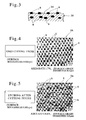
- Figure 4 is an enlarged photograph of the first sliding surface 3A (surface) that is the surface of the base material 3B in the case where it is finished with only cutting and no etching is applied thereon.
- those displayed as very small black points are the granular Mn-Si compounds 6.
- the ratio of the area of the Mn-Si compounds 6 exposed on the first sliding surface 3A to the range of the first sliding surface 3A shown in Figure 4 was 1.7%, and the average diameter of the grains of the exposed Mn-Si compounds 6 was 4.6 ⁇ m.
- the ratio of 1.7% of the area of the Mn-Si compounds 6 exposed on the first sliding surface 3A in the range shown in Figure 4 can be considered to be practically the ratio of the exposed area of the Mn-Si compounds 6 with respect to the entire region of the first sliding surface 3A. This is the same as in the above described embodiment in which etching is applied to the first sliding surfaces 3A.
- the exposed amount of the granular Mn-Si compounds 6 exposed on the first sliding surface 3A (surface of the base material 3B) obviously increases as compared with the above described Figure 4.
- the ratio of the area of the Mn-Si compounds 6 exposed on the first sliding surface 3A was 6.6%, and the average diameter of the grains of the exposed Mn-Si compounds 6 was 5.6 ⁇ m.
- the Mn-Si compounds 6 exposed on the first sliding surface 3A are increased.
- the first sliding surface 3A becomes inferior in wettability for holding lubricating oil.
- the exposed amount of the Mn-Si compounds 6 is increased as described above without making the roughness of the first sliding surface 3A too small, and wettability of the first sliding surface 3A is made favorable.
- the shoe 4 of the embodiment is constituted of SUJ2 that is an iron material
- projected portions 4a are formed in a lattice form on its flat second sliding surface 4A as shown in Figure 7, and the portion other than the projected portions 4a are relatively made recessed portions 4b, whereby the surface with recesses and projections is formed on the above described second sliding surface 4A.
- the above described projected portions 4a are formed by irradiating the above described second sliding surface 4A with laser, and directly quenching the second sliding surface 4A by irradiation.
- the irradiated portion irradiated with the above described layer is in the state in which the base material surface 4c forming the original surface of the second sliding surface 4A is directly quenched and bulges from the base material surface 4c, and thereby the projected portions 4a are formed, as shown in Figure 8.
- the portion irradiated with laser is in the state directly quenched like this, the recessed portions 4b, which are adjacent to the portions irradiated with laser and are not directly irradiated with laser, are not directly quenched, and the portions become non-directly quenched portions.
- the non-directly quenched portions relatively recess with respect to the above described projected portions 4a, and the recessed portions 4b are formed.
- the quenching range by irradiation of laser is semicircular in section with the irradiation position of the laser as the center as shown by the phantom line 7 in, for example, Figure 8, and therefore, by narrowing the space of the adjacent irradiations of laser, quenching can be performed in the recessed portion 4b of the non-directly quenched portion which is in the middle of them. It can be set by the irradiation space of laser whether the portion of the recessed portion 4b that is the non-directly quenched portion is quenched or not. If the recessed portion 4b that is the non-direct quenched portion is quenched, the portion bulges from the base member surface 4c though it does not bulge so much as the convex portion 4a.
- YAG laser is linearly irradiated to the second sliding surface 4A of the shoe 4 produced of SUJ2 to be parallel at the spaces of 0.2 mm
- the space is desirably in the range of 0.1 to 0.3 mm.
- the output of the above described YAG laser is 50 W, and the YAG laser is irradiated by adjusting the condenser lens so that the YAG laser comes into a focus in the position at the depth of 2 mm with respect to the surface of the second sliding surface 4A, that is, in the state in which the YAG laser is out of focus with respect to the surface of the second sliding surface 4A.
- the surface of the projected portion 4a that is the directly quenched portion irradiated with the above described laser increases in hardness by about Hv 100 with respect to Hv 750 that is the hardness of the base material, and the surface of the recessed portion 4b increases by about Hv 50.
- a portion 8 that is a slightly deeper than the directly quenched portion is annealed and becomes lower in hardness than the base material by about Hv 100
- the point of intersection of the projected portion 4a and the projected portion 4a that are the directly quenched portions that is, the portion where the portions irradiated with laser intersect each other is also annealed, and becomes lower in hardness than the base material by about Hv 100.
- quenching by laser is abruptly cooled, and therefore, reduction in hardness of the base material is not recognized in the position deeper than the above described slightly deeper portion 6.
- the height of the projected portion 4a with respect to the above described recessed portion 4b is about 0.1 to 10 ⁇ m immediately after laser treatment, and is desirably in the range of 0.1 to 1 ⁇ m in the finished product after lapping and buffing.
- SUJ2 is used as the material of the shoe, but the material is not limited to this, and it goes without saying that other iron materials may be used.
- Figure 6 shows the result of the test of seizure resistance which was conducted with respect to the sliding device 1 of the embodiment constituted of the swash plate 3 and the shoe 4 adapted as described above, and the sliding device (prior art) including the conventional ordinary swash plate.
- the test conditions are as follows. Rotational frequency of the swash plate: 9000 rpm (the rotational frequency is increased by 1000 rpm for one minute for each of nine steps)
- the seizure loads of the sliding device which is the prior art using the conventional swash plate are all 5 MPa or less.
- the seizure loads of the sliding device 1 of the embodiment are all 15 MPa or more, and it can be understood that the sliding device 1 includes excellent seizure resistance.
- the reason of the sliding device 1 of the embodiment including excellent seizure resistance like this the following matter is conceivable. Namely, a number of granular Mn-Si compounds are uniformly exposed on the first sliding surface 3A of the swash plate 3, and they are in the state slightly bulging from the surface of the original base material 3B (see Figures 2 and 3).
- the contact pressure acting on the first sliding surface 3A of the swash plate 3 from the second sliding surface 4A of the shoe 4 is supported by a number of Mn-Si compounds 6 and reduced. Therefore, the contact pressure acting on the first sliding surface 3A of the swash plate 3 from the shoe 4 can be reduced more than in the sliding device using the conventional ordinary swash plate.
- a number of Mn-Si compounds 6 are granular and exposed on the first sliding surface 3A of the swash plate 3, whereby very small space portions continuing to one another exist in the positions adjacent to them, and the very small space portions function as the flow passage of the lubricating oil.
- the exposed amount of the Mn-Si compounds 6 is increased without making the roughness of the first sliding surface 3A too small, and thereby, wettability of the lubricating oil to the first sliding surface 3A becomes favorable. It is conceivable that for the above reason, the sliding device 1 of the embodiment includes excellent seizure resistance as described above.
- the sliding device 1 at low manufacturing cost and excellent in seizure resistance can be provided.
- etching By applying etching to the first sliding surface 3A after cutting, very small burrs and scars occurring to the first sliding surface 3A at the time of cutting can be removed.
- the manufacturing cost of the sliding device 1 can be made low by the amount of omission of the working step for removing such burrs and the like.
- the load capacity of the second sliding surface 4A of the shoe 4 can be enhanced, and the sliding device 1 excellent in abrasion resistance can be provided ultimately.
- Figure 9 shows a sectional view of the swash plate 3 of the sliding device 1 that is a second embodiment of the present invention.
- surface treatment is not applied to the first sliding surface 3A of the swash plate 3, but in the second embodiment, with the constitution of the swash plate 3 of the above described first embodiment as the precondition, Sn plating of a thickness of 0.3 to 3 ⁇ m is applied to the whole first sliding surface 3A.
- the other constitutions in the second embodiment are the same as those in the sliding device 1 of the above described first embodiment, and therefore, the explanation of them will be omitted.
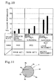
- Figure 10 shows the test result of the seizure resistance of the sliding devices 1 of the second embodiment and the prior arts 1 and 2.
- the swash plate is constituted of a high strength brass material containing Mn and Si, and the show is constituted of SUJ2 without laser quenching.
- the swash plate is constituted of the same high strength brass material including Mn and Si as in the embodiment, with Sn plating applied to the sliding surface, and the shoe is constituted of SUJ2 without laser quenching.
- the test conditions are as follows, the test was conducted twice on each of the prior arts 1 and 2 and the embodiment. The left side of each of the tested object shows the result of the first test, and the right side shows the result of the second test. (Test conditions) Swash plate rotational frequency: the rotational frequency is increased by 1000 rpm for one minute for each of nine steps: Maximum rotational frequency 9000 rpm (circumferential speed 38 m/s)
- the sliding device 1 of the second embodiment is 13.5 MPa or 16.2 MPa
- the sliding device 1 of the second embodiment obviously includes excellent seizure resistance as compared with the conventional sliding devices, and can obtain the same operation and effect as the above described first embodiment.
- the first sliding surface 3A of the swash plate 3 at the time of start of use is constituted of Sn plating 3C, and therefore, conformability of the first sliding surface 3A of the swash plate 3 and the second sliding surface 4A of the shoe 4 can be enhanced.
- Sn plating is applied to the whole first sliding surface 3A of the swash plate 3, but as the surface treatment substituting as it, any one of solder alloy plating and resin coating may be adopted.
- Figures 11 and 12 show other embodiments when laser quenching is applied to the shoe 4.
- laser is irradiated to the second sliding surface 4A with the locus of movement drawing equidistant parallel lines to form the projected portions 4a and the recessed portions 4b.
- Figure 12 shows that for the second sliding surface 4A of the shoe 4, quenching is performed by irradiating laser to the second sliding surface 4A so as to draw a number of concentric circles with the center of the second sliding surface 4A as the center.
- the projected portions 4a are formed at the laser irradiation positions, and the recessed portions 4b are formed in the adjacent positions to them.
- Figure 13 shows another embodiment in the case where laser quenching is performed for the shoe 4.
- laser is irradiated so that a number of circles are disposed in a staggered form all over the second sliding surface 4A of the shoe 4.
- the position of each of the circles irradiated with laser becomes the projected portion 4a, and its inside and outside portions are formed as the recessed portions 4b.
Landscapes
- Engineering & Computer Science (AREA)
- General Engineering & Computer Science (AREA)
- Mechanical Engineering (AREA)
- Manufacturing & Machinery (AREA)
- Compressors, Vaccum Pumps And Other Relevant Systems (AREA)
- Sliding-Contact Bearings (AREA)
Abstract
Description
- The present invention relates to a sliding device, and more particularly relates to a sliding device including a swash plate and a shoe sliding with it.
- Conventionally, as a sliding device used in a swash plate type compressor, the one including a swash plate having a flat first sliding surface formed on at least one end surface, and a shoe having a flat second sliding surface sliding with the first sliding surface of the above described swash plate is known (for example,
Patent Document 1, Patent Document 2).
Patent Document 1:Japanese Patent Laid-Open No. 10-153169
Patent Document 2:Japanese Patent Laid-Open No. 2002-317757 - Incidentally, the above described conventional swash plate type compressor has come to be used recently under the condition of a high speed and a high load and under the condition with a small amount of lubricating oil. The operation conditions of the sliding device have become increasingly severe recently, and therefore, the swash plates and shoes significantly wear, and seizure of them easily occurs.
Conventionally, there are the sliding devices with high strength brass used as the material of the above described swash plates, and the swash plates using such high strength brass have the disadvantage of having low seizure resistance while their manufacturing cost is low. Means to solve the issues - In view of the above described circumstances, the present invention is such that in a sliding device including a swash plate having a flat first sliding surface formed on at least one end surface, and a shoe having a flat second sliding surface sliding with the first sliding surface of the above described swash plate,
the above described swash plate includes a base material constituted of high strength brass containing Mn and Si, and an Mn-Si compound is exposed on a surface to be the above described first sliding surface in the base material, and
the above described shoe is constituted of an iron material and very small recesses and projections are formed on the second sliding surface of the shoe by laser quenching. - According to the above constitution, as is obvious from the test results which will be described later, the sliding device favorable in seizure resistance as compared with the conventional sliding devices and low in manufacturing cost can be provided.
- Describing the present invention with respect to embodiments illustrated in the drawings, a
sliding device 1 is provided in a housing of a swash plate type compressor in Figure 1. Thesliding device 1 is constituted of aswash plate 3 mounted slantly to arotary shaft 2 pivotally supported in the above described housing, and a plurality ofshoes 4 sliding with theswash plate 3.
Theswash plate 3 is formed into a disk shape, and both end surfaces in theswash plate 3 becomes flat first slidingsurfaces shoes 4.
Meanwhile, theshoe 4 is formed into a semispherical shape as a whole, and is constituted of a flat second slidingsurface 4A sliding with the first slidingsurface 3A of the above describedswash plate 3, and asemispherical convex surface 4B which is semispherical. - In the housing of the above described swash plate type compressor, a plurality of
pistons 5 are disposed to be parallel with and surround therotary shaft 2. A set of twoshoes 4 are slidably held in an arc-shaped notchedportion 5A formed at one end of each of thepistons 5, the notchedportion 5A in this state is disposed to enwrap the outer peripheral portion of the above describedswash plate 3, and the second slidingsurfaces 4A of theshoes 4 of the set are allowed to abut on the first slidingsurfaces 3A of theswash plate 3.
When the above describedrotary shaft 2 is rotated, theswash plate 3 rotates, the firstsliding surfaces 3A which are both end surfaces of theswash plate 3 and the second slidingsurfaces 4A of theshoes 4 of each set slide, and with this, each of thepistons 5 are moved to advance and retreat in the axial direction via theshoes 4 of each set.
The above-described configuration remains the same as that of a conventional well-known sliding device. - Thus, the embodiment enhances seizure resistance of the
sliding device 1 by improving thesliding device 1 including the above describedswash plate 3 and theshoes 4 as follows.
Namely, theswash plate 3 of the embodiment is constituted of abase material 3B constituted of high strength brass containing 2 to 3.5 mass percent of Mn, and 0.5 to 1.5 mass percent of Si.
In the embodiment, thebase material 3B constituted of the above described high strength brass is formed into a disk shape as a whole by cutting first, and thereafter, etching is applied to the entire region of the first slidingsurface 3A to finish the work.
As shown in Figures 2 and 3, hard and very small granular Mn-Si compounds 6 are uniformly exposed on the inside of thebase material 3B and the firstsliding surfaces 3A that is the surface. In the embodiment, by applying etching to the entire region of the first slidingsurface 3A after cutting as described above, the exposed amount of the granular Mn-Si compounds 6 exposed on the first slidingsurface 3A that is the surface of thebase material 3B is increased. - The study of the inventor of the present application proves that the Mn-
Si compounds 6 are exposed on the first slidingsurface 3A and the inside of thebase material 3B without applying etching to the first slidingsurface 3A, but by applying etching, the exposed amount of the Mn-Si compounds 6 exposed on the first slidingsurface 3A that is the surface of thebase material 3B increases. Thus, in the embodiment, etching is applied to the first slidingsurface 3A that is the surface of thebase material 3B after cutting work.
Etching is performed by submerging the base material to be theswash plate 3 after cutting work into the solution for etching containing sulfuric acid and hydrogen peroxide solution.
Figure 4 is an enlarged photograph of the first slidingsurface 3A (surface) that is the surface of thebase material 3B in the case where it is finished with only cutting and no etching is applied thereon. In Figure 4, those displayed as very small black points are the granular Mn-Si compounds 6. As shown in Figure 4, when no etching is applied with only cutting finish, the ratio of the area of the Mn-Si compounds 6 exposed on the first slidingsurface 3A to the range of the first slidingsurface 3A shown in Figure 4 was 1.7%, and the average diameter of the grains of the exposed Mn-Si compounds 6 was 4.6 µm.
Since the Mn-Si compounds 6 are uniformly exposed on the entire region of the first slidingsurface 3A, the ratio of 1.7% of the area of the Mn-Si compounds 6 exposed on the first slidingsurface 3A in the range shown in Figure 4 can be considered to be practically the ratio of the exposed area of the Mn-Si compounds 6 with respect to the entire region of the first slidingsurface 3A. This is the same as in the above described embodiment in which etching is applied to the firstsliding surfaces 3A. - Meanwhile, as shown in Figure 5, in the embodiment in which etching is applied to the first sliding
surface 3A of thebase material 3B after the above described cutting is performed, the exposed amount of the granular Mn-Si compounds 6 exposed on the first slidingsurface 3A (surface of thebase material 3B) obviously increases as compared with the above described Figure 4. In the embodiment shown in the above described Figure 5, the ratio of the area of the Mn-Si compounds 6 exposed on the first slidingsurface 3A was 6.6%, and the average diameter of the grains of the exposed Mn-Si compounds 6 was 5.6 µm.
As above, in the embodiment, by applying etching to the first slidingsurface 3A of thebase material 3B after cutting work, the Mn-Si compounds 6 exposed on the first slidingsurface 3A are increased. Thereby, a number of very small projected portions are formed over the entire region of the first slidingsurface 3A by the grains of Mn-Sicompounds 6, and very small space portions continuing to one another are formed in the positions adjacent to the grains.
By applying etching to the first slidingsurface 3A of theswash plate 3 after cutting work, very small burrs and scars occurring to the first slidingsurface 3A at the time of cutting work can be removed. - Further, when machining such as cutting and lapping is applied to the above described first sliding
surface 3A, if the ratio of the Mn-Si compounds 6 exposed on the first slidingsurface 3A is to be enhanced, the roughness of the first slidingsurface 3A becomes small. Thereupon, the first slidingsurface 3A becomes inferior in wettability for holding lubricating oil.
On the other hand, in the case of the embodiment in which etching is applied to the first slidingsurface 3A after cutting, the exposed amount of the Mn-Si compounds 6 is increased as described above without making the roughness of the first slidingsurface 3A too small, and wettability of the first slidingsurface 3A is made favorable. - Meanwhile, the
shoe 4 of the embodiment is constituted of SUJ2 that is an iron material, projectedportions 4a are formed in a lattice form on its flat second slidingsurface 4A as shown in Figure 7, and the portion other than the projectedportions 4a are relatively made recessedportions 4b, whereby the surface with recesses and projections is formed on the above described second slidingsurface 4A.
The above described projectedportions 4a are formed by irradiating the above described second slidingsurface 4A with laser, and directly quenching the second slidingsurface 4A by irradiation. Namely, the irradiated portion irradiated with the above described layer is in the state in which thebase material surface 4c forming the original surface of the second slidingsurface 4A is directly quenched and bulges from thebase material surface 4c, and thereby the projectedportions 4a are formed, as shown in Figure 8.
The portion irradiated with laser is in the state directly quenched like this, therecessed portions 4b, which are adjacent to the portions irradiated with laser and are not directly irradiated with laser, are not directly quenched, and the portions become non-directly quenched portions. The non-directly quenched portions relatively recess with respect to the above described projectedportions 4a, and the recessedportions 4b are formed. - However, it is not that the
recessed portion 4b which is the non-directly quenched portion is not quenched. Namely, the quenching range by irradiation of laser is semicircular in section with the irradiation position of the laser as the center as shown by thephantom line 7 in, for example, Figure 8, and therefore, by narrowing the space of the adjacent irradiations of laser, quenching can be performed in the recessedportion 4b of the non-directly quenched portion which is in the middle of them. It can be set by the irradiation space of laser whether the portion of the recessedportion 4b that is the non-directly quenched portion is quenched or not. If therecessed portion 4b that is the non-direct quenched portion is quenched, the portion bulges from thebase member surface 4c though it does not bulge so much as theconvex portion 4a. - In the embodiment, after YAG laser is linearly irradiated to the second sliding
surface 4A of theshoe 4 produced of SUJ2 to be parallel at the spaces of 0.2 mm, irradiates the YAG laser parallel at the spaces of 0.2 mm in the direction orthogonal to this, and the YAG laser is irradiated in the lattice form as a whole. The space is desirably in the range of 0.1 to 0.3 mm.
The output of the above described YAG laser is 50 W, and the YAG laser is irradiated by adjusting the condenser lens so that the YAG laser comes into a focus in the position at the depth of 2 mm with respect to the surface of the second slidingsurface 4A, that is, in the state in which the YAG laser is out of focus with respect to the surface of the second slidingsurface 4A.
The surface of the projectedportion 4a that is the directly quenched portion irradiated with the above described laser increases in hardness by about Hv 100 with respect to Hv 750 that is the hardness of the base material, and the surface of the recessedportion 4b increases by about Hv 50. On the other hand, a portion 8 (see Figure 8) that is a slightly deeper than the directly quenched portion is annealed and becomes lower in hardness than the base material by about Hv 100, the point of intersection of the projectedportion 4a and the projectedportion 4a that are the directly quenched portions, that is, the portion where the portions irradiated with laser intersect each other is also annealed, and becomes lower in hardness than the base material by about Hv 100. However, quenching by laser is abruptly cooled, and therefore, reduction in hardness of the base material is not recognized in the position deeper than the above described slightlydeeper portion 6.
In the embodiment, after laser is irradiated to the second slidingsurfaces 4A of theshoe 4 as described above, lapping and buffing are applied in sequence and the shoe is completed. The height of the projectedportion 4a with respect to the above describedrecessed portion 4b is about 0.1 to 10 µm immediately after laser treatment, and is desirably in the range of 0.1 to 1 µm in the finished product after lapping and buffing.
In the embodiment, SUJ2 is used as the material of the shoe, but the material is not limited to this, and it goes without saying that other iron materials may be used. - Next, Figure 6 shows the result of the test of seizure resistance which was conducted with respect to the
sliding device 1 of the embodiment constituted of theswash plate 3 and theshoe 4 adapted as described above, and the sliding device (prior art) including the conventional ordinary swash plate. The test conditions are as follows.
Rotational frequency of the swash plate: 9000 rpm (the rotational frequency is increased by 1000 rpm for one minute for each of nine steps) - Contact pressure: preload 2.7 MPa Contact pressure is increased every minute by b2.7 MPa until seized.
- Oil mist amount: 0.05 g/min
- Oil: refrigerating machine oil
- Seizure determination: Axial torque max. 4.0 N/m
- As can be understood from Figure 6, the seizure loads of the sliding device which is the prior art using the conventional swash plate are all 5 MPa or less. On the other hand, the seizure loads of the sliding
device 1 of the embodiment are all 15 MPa or more, and it can be understood that the slidingdevice 1 includes excellent seizure resistance.
As the reason of the slidingdevice 1 of the embodiment including excellent seizure resistance like this, the following matter is conceivable.
Namely, a number of granular Mn-Si compounds are uniformly exposed on the first slidingsurface 3A of theswash plate 3, and they are in the state slightly bulging from the surface of theoriginal base material 3B (see Figures 2 and 3). Therefore, when the second slidingsurface 4A of theshoe 4 as the counterpart member and the first slidingsurface 3A of theswash plate 3 slide, the contact pressure acting on the first slidingsurface 3A of theswash plate 3 from the second slidingsurface 4A of theshoe 4 is supported by a number of Mn-Si compounds 6 and reduced. Therefore, the contact pressure acting on the first slidingsurface 3A of theswash plate 3 from theshoe 4 can be reduced more than in the sliding device using the conventional ordinary swash plate.
Further, in the embodiment, a number of Mn-Si compounds 6 are granular and exposed on the first slidingsurface 3A of theswash plate 3, whereby very small space portions continuing to one another exist in the positions adjacent to them, and the very small space portions function as the flow passage of the lubricating oil.
Further, in the case of the embodiment in which etching is applied to the first slidingsurface 3A after cutting, the exposed amount of the Mn-Si compounds 6 is increased without making the roughness of the first slidingsurface 3A too small, and thereby, wettability of the lubricating oil to the first slidingsurface 3A becomes favorable.
It is conceivable that for the above reason, the slidingdevice 1 of the embodiment includes excellent seizure resistance as described above. - As described above, according to the embodiment, less expensive high strength brass is used as the
swash plate 3, and therefore, the slidingdevice 1 at low manufacturing cost and excellent in seizure resistance can be provided.
By applying etching to the first slidingsurface 3A after cutting, very small burrs and scars occurring to the first slidingsurface 3A at the time of cutting can be removed. The manufacturing cost of the slidingdevice 1 can be made low by the amount of omission of the working step for removing such burrs and the like.
Since a number of very small recesses and projections are formed by applying the above described laser quenching to the second slidingsurface 4A of theshoe 4 of the embodiment, the load capacity of the second slidingsurface 4A of theshoe 4 can be enhanced, and the slidingdevice 1 excellent in abrasion resistance can be provided ultimately. - Next, Figure 9 shows a sectional view of the
swash plate 3 of the slidingdevice 1 that is a second embodiment of the present invention. In theswash plate 3 of the slidingdevice 1 of the above described first embodiment, surface treatment is not applied to the first slidingsurface 3A of theswash plate 3, but in the second embodiment, with the constitution of theswash plate 3 of the above described first embodiment as the precondition, Sn plating of a thickness of 0.3 to 3 µm is applied to the whole first slidingsurface 3A. The other constitutions in the second embodiment are the same as those in the slidingdevice 1 of the above described first embodiment, and therefore, the explanation of them will be omitted.
Next, Figure 10 shows the test result of the seizure resistance of the slidingdevices 1 of the second embodiment and theprior arts prior art 1, the swash plate is constituted of a high strength brass material containing Mn and Si, and the show is constituted of SUJ2 without laser quenching. Further, in theprior art 2, the swash plate is constituted of the same high strength brass material including Mn and Si as in the embodiment, with Sn plating applied to the sliding surface, and the shoe is constituted of SUJ2 without laser quenching.
The test conditions are as follows, the test was conducted twice on each of theprior arts
(Test conditions)
Swash plate rotational frequency: the rotational frequency is increased by 1000 rpm for one minute for each of nine steps: Maximum rotational frequency 9000 rpm
(circumferential speed 38 m/s) - Contact pressure: with preload 2.7 MPa, the contact pressure is increased by 2.7 MPa every minute: until seized
- Oil mist amount: 0.05 to 0.25 g/min Nozzle position fixed.
- Oil: refrigerating machine oil
- Seizure condition: Axial torque over 4.0 N/m
- As can be understood from the test result shown in Figure 10, while the seizure loads of the sliding devices of the
prior arts device 1 of the second embodiment is 13.5 MPa or 16.2 MPa, and the slidingdevice 1 of the second embodiment obviously includes excellent seizure resistance as compared with the conventional sliding devices, and can obtain the same operation and effect as the above described first embodiment.
In the second embodiment, the first slidingsurface 3A of theswash plate 3 at the time of start of use is constituted of Sn plating 3C, and therefore, conformability of the first slidingsurface 3A of theswash plate 3 and the second slidingsurface 4A of theshoe 4 can be enhanced.
In the second embodiment shown in Figure 9, Sn plating is applied to the whole first slidingsurface 3A of theswash plate 3, but as the surface treatment substituting as it, any one of solder alloy plating and resin coating may be adopted. - Next, Figures 11 and 12 show other embodiments when laser quenching is applied to the
shoe 4. Namely, in Figure 11, on laser quenching of the second slidingsurface 4A of theshoe 4, laser is irradiated to the second slidingsurface 4A with the locus of movement drawing equidistant parallel lines to form the projectedportions 4a and the recessedportions 4b.
Figure 12 shows that for the second slidingsurface 4A of theshoe 4, quenching is performed by irradiating laser to the second slidingsurface 4A so as to draw a number of concentric circles with the center of the second slidingsurface 4A as the center. In this embodiment, the projectedportions 4a are formed at the laser irradiation positions, and the recessedportions 4b are formed in the adjacent positions to them.
Further, Figure 13 shows another embodiment in the case where laser quenching is performed for theshoe 4. In the embodiment shown in Figure 13, laser is irradiated so that a number of circles are disposed in a staggered form all over the second slidingsurface 4A of theshoe 4. Thereby, the position of each of the circles irradiated with laser becomes the projectedportion 4a, and its inside and outside portions are formed as the recessedportions 4b. -
- Figure 1 is a sectional view of an essential part showing one embodiment of the present invention;
- Figure 2 is an enlarged view of a first sliding
surface 3A of a swash plate shown in Figure 1; - Figure 3 is a sectional view taken along the line III-III of Figure 2;
- Figure 4 is a view showing an enlarged photograph of the first sliding surface of the swash plate to which only cutting is applied;
- Figure 5 is a view showing an enlarged photograph of the first sliding surface of the swash plate of the embodiment shown in Figure 2;
- Figure 6 is a diagram showing the test result of seizure resistance of the embodiment shown in Figure 1 and a prior art;
- Figure 7 is a front view of a second sliding
surface 4A of ashoe 4 shown in Figure 1; - Figure 8 is a sectional view of the essential part taken along the VIII-VIII line of Figure 7;
- Figure 9 is a sectional view of an essential part of a swash plate as a second embodiment of the present invention;
- Figure 10 is a diagram showing the test result of the seizure resistance of the second embodiment shown in Figure 9 and the prior arts;
- Figure 11 is a front view of a second sliding surface showing another embodiment of the shoe;
- Figure 12 is a front view of the second sliding surface showing another embodiment of the shoe; and
- Figure 13 is a front view of the second sliding surface showing another embodiment of the shoe.
-
1 ... sliding device 3 ... swash plate 3A ... first sliding surface 3B ... base material 4 ... shoe surface 4A ... second sliding 4a ... projected portion 4b ... recessed portion 6 ... Mn-Si compound
Claims (6)
- A sliding device including a swash plate having a flat first sliding surface formed on at least one end surface, and a shoe having a flat second sliding surface which slides with the first sliding surface of said swash plate, characterized in that
said swash plate includes a base material constituted of high strength brass containing Mn and Si, and an Mn-Si compound is exposed on a surface to be said first sliding surface in the base material, and
said shoe is constituted of an iron material, and very small recesses and projections are formed on the second sliding surface of the shoe by laser quenching. - The sliding device according to claim 1, characterized in that
an exposed amount of the Mn-Si compound which is exposed on the surface to be said first sliding surface is increased on the surface of the base material of said swash plate by removing the base material. - The sliding device according to claim 1 or claim 2, characterized in that
surface treatment of any one of Sn plating, solder alloy plating and resin coating is applied to whole the first sliding surface on which said Mn-Si compound is exposed. - The sliding device according to any one of claims 1 to 3, characterized in that
the base material of said swash plate is high strength brass containing 2 to 3.5 mass percent of Mn and 0.5 to 1.5 mass percent of Si. - The sliding device according to any one of claims 1 to 4, characterized in that
laser quenching of the second sliding surface of said shoe is performed by irradiating laser to said second sliding surface with a movement locus being in a lattice form, a parallel straight line form or a concentric circle form. - The sliding device according to any one of claims 1 to 5, characterized in that
said Mn-Si compound granularly exposed on the first sliding surface of said swash plate, an average diameter of the granular Mn-Si compound is 3 to 10 µm, a ratio of exposure area of the Mn-Si compound with respect to an area of the first sliding surface is 3 to 15%.
Applications Claiming Priority (3)
| Application Number | Priority Date | Filing Date | Title |
|---|---|---|---|
| JP2004328164 | 2004-11-11 | ||
| JP2005130576A JP4817039B2 (en) | 2004-11-11 | 2005-04-27 | Sliding device |
| PCT/JP2005/017944 WO2006051656A1 (en) | 2004-11-11 | 2005-09-29 | Slider |
Publications (2)
| Publication Number | Publication Date |
|---|---|
| EP1811173A1 true EP1811173A1 (en) | 2007-07-25 |
| EP1811173A4 EP1811173A4 (en) | 2013-02-13 |
Family
ID=36336339
Family Applications (1)
| Application Number | Title | Priority Date | Filing Date |
|---|---|---|---|
| EP05788175A Withdrawn EP1811173A4 (en) | 2004-11-11 | 2005-09-29 | SLIDING ASSEMBLY |
Country Status (6)
| Country | Link |
|---|---|
| US (1) | US7892656B2 (en) |
| EP (1) | EP1811173A4 (en) |
| JP (1) | JP4817039B2 (en) |
| KR (1) | KR100839095B1 (en) |
| BR (1) | BRPI0518385A2 (en) |
| WO (1) | WO2006051656A1 (en) |
Cited By (1)
| Publication number | Priority date | Publication date | Assignee | Title |
|---|---|---|---|---|
| EP1854897A4 (en) * | 2005-01-17 | 2012-04-25 | Taiho Kogyo Co Ltd | METHOD FOR MANUFACTURING A SLIPPER MEMBER |
Families Citing this family (10)
| Publication number | Priority date | Publication date | Assignee | Title |
|---|---|---|---|---|
| JP2009097492A (en) * | 2007-09-27 | 2009-05-07 | Toyota Industries Corp | Swash plate type compressor |
| JP5229576B2 (en) | 2009-01-30 | 2013-07-03 | 大豊工業株式会社 | Swash plate compressor |
| JP5253440B2 (en) * | 2010-03-01 | 2013-07-31 | 大同メタル工業株式会社 | Sliding bearings for turbochargers for internal combustion engines |
| JP5472630B2 (en) * | 2010-07-27 | 2014-04-16 | 大豊工業株式会社 | Sliding member and manufacturing method thereof |
| JP5594466B2 (en) | 2010-07-28 | 2014-09-24 | 大豊工業株式会社 | Swash plate compressor |
| JP2012062763A (en) * | 2010-09-14 | 2012-03-29 | Taiho Kogyo Co Ltd | Rotary type compressor |
| JP5436510B2 (en) * | 2011-10-06 | 2014-03-05 | 大同メタル工業株式会社 | Copper-based sliding material |
| CN103182683B (en) * | 2011-12-30 | 2017-03-08 | 广州江瑞机电设备有限公司 | The method of pattern-making and metal shell obtained by this method on metal shell |
| US10760563B2 (en) | 2015-09-07 | 2020-09-01 | Panasonic Intellectual Property Management Co., Ltd. | Refrigerant compressor and refrigeration device including refrigerant compressor |
| DE102020101311A1 (en) * | 2020-01-21 | 2021-07-22 | Nidec Gpm Gmbh | Friction-optimized vacuum orbiter pump |
Family Cites Families (15)
| Publication number | Priority date | Publication date | Assignee | Title |
|---|---|---|---|---|
| US3337335A (en) * | 1964-06-08 | 1967-08-22 | Mueller Brass Company | Leaded silicon manganese bearing brass |
| JPS512414B1 (en) * | 1970-10-30 | 1976-01-26 | ||
| JPS512414A (en) | 1974-04-18 | 1976-01-10 | Matsushita Electric Industrial Co Ltd | Supiikasochi |
| JPS59107081A (en) * | 1982-12-08 | 1984-06-21 | Mazda Motor Corp | Method for etching cylinder made of aluminum alloy |
| JPS6017013A (en) * | 1983-07-05 | 1985-01-28 | Kobe Steel Ltd | Production of steel having mixed composition |
| JPS61117240A (en) | 1984-11-14 | 1986-06-04 | Hitachi Ltd | Material for bearing for supercharger |
| JPS62133016A (en) * | 1985-12-05 | 1987-06-16 | Mitsubishi Electric Corp | Hardening method for sliding surface |
| JPH0697033B2 (en) * | 1988-11-11 | 1994-11-30 | 株式会社豊田自動織機製作所 | Swash plate type compressor |
| JPH0726088B2 (en) * | 1988-12-23 | 1995-03-22 | 三菱電機株式会社 | High friction sliding material |
| JPH02173212A (en) * | 1988-12-26 | 1990-07-04 | Hitachi Ltd | Sliding material and its surface treatment method |
| JPH03111522A (en) * | 1989-09-25 | 1991-05-13 | Hitachi Ltd | Production of sliding parts of aluminum or aluminum alloy |
| JPH07113421A (en) * | 1992-03-13 | 1995-05-02 | Tone Corp | Sliding member having good abrasion resistance and lubricating performance and manufacture thereof |
| US5282908A (en) * | 1992-11-03 | 1994-02-01 | Chuetsu Metal Works Co., Ltd. | High strength α brass containing Mn, Si, Co, Fe, Sn and Pb |
| JPH10153169A (en) * | 1996-11-21 | 1998-06-09 | Sanden Corp | Swash plate variable capacity compressor |
| JP2002317757A (en) | 2001-04-20 | 2002-10-31 | Toyota Industries Corp | Swash plate in variable displacement swash plate-type compressor |
-
2005
- 2005-04-27 JP JP2005130576A patent/JP4817039B2/en not_active Expired - Fee Related
- 2005-09-29 BR BRPI0518385-5A patent/BRPI0518385A2/en not_active Application Discontinuation
- 2005-09-29 WO PCT/JP2005/017944 patent/WO2006051656A1/en not_active Ceased
- 2005-09-29 US US11/662,249 patent/US7892656B2/en not_active Expired - Fee Related
- 2005-09-29 KR KR1020077007217A patent/KR100839095B1/en not_active Expired - Fee Related
- 2005-09-29 EP EP05788175A patent/EP1811173A4/en not_active Withdrawn
Cited By (1)
| Publication number | Priority date | Publication date | Assignee | Title |
|---|---|---|---|---|
| EP1854897A4 (en) * | 2005-01-17 | 2012-04-25 | Taiho Kogyo Co Ltd | METHOD FOR MANUFACTURING A SLIPPER MEMBER |
Also Published As
| Publication number | Publication date |
|---|---|
| US20070266808A1 (en) | 2007-11-22 |
| KR100839095B1 (en) | 2008-06-19 |
| US7892656B2 (en) | 2011-02-22 |
| JP4817039B2 (en) | 2011-11-16 |
| EP1811173A4 (en) | 2013-02-13 |
| JP2006161801A (en) | 2006-06-22 |
| KR20070048265A (en) | 2007-05-08 |
| WO2006051656A1 (en) | 2006-05-18 |
| BRPI0518385A2 (en) | 2008-11-18 |
Similar Documents
| Publication | Publication Date | Title |
|---|---|---|
| EP1811173A1 (en) | Slider | |
| EP2672132A2 (en) | Method of manufacturing bearing ring of rolling bearing | |
| KR20160037909A (en) | Sliding member, chain link, and chain comprising said link | |
| EP1876352B1 (en) | Sliding device | |
| KR100870675B1 (en) | Shoe | |
| EP1795751B1 (en) | Sliding surface of sliding member | |
| US7222425B2 (en) | Method of forming engine bearing | |
| KR20070091327A (en) | Manufacturing method of the sliding member | |
| CN100451332C (en) | sliding device | |
| JP3925730B2 (en) | Shoe | |
| JP3880009B2 (en) | Manufacturing method of sliding member | |
| JP4075899B2 (en) | Manufacturing method of swash plate | |
| JP3932138B2 (en) | Manufacturing method of sliding member. | |
| JP4466687B2 (en) | Sliding member and manufacturing method thereof | |
| JP3931991B2 (en) | Shoe | |
| JP4075904B2 (en) | Shoe manufacturing method | |
| JP2005127151A (en) | Compressor parts and manufacturing method thereof |
Legal Events
| Date | Code | Title | Description |
|---|---|---|---|
| PUAI | Public reference made under article 153(3) epc to a published international application that has entered the european phase |
Free format text: ORIGINAL CODE: 0009012 |
|
| 17P | Request for examination filed |
Effective date: 20070509 |
|
| AK | Designated contracting states |
Kind code of ref document: A1 Designated state(s): AT BE BG CH CY CZ DE DK EE ES FI FR GB GR HU IE IS IT LI LT LU LV MC NL PL PT RO SE SI SK TR |
|
| DAX | Request for extension of the european patent (deleted) | ||
| A4 | Supplementary search report drawn up and despatched |
Effective date: 20130111 |
|
| RIC1 | Information provided on ipc code assigned before grant |
Ipc: F04B 27/10 20060101ALI20130107BHEP Ipc: F04B 27/08 20060101AFI20130107BHEP |
|
| 17Q | First examination report despatched |
Effective date: 20180213 |
|
| STAA | Information on the status of an ep patent application or granted ep patent |
Free format text: STATUS: THE APPLICATION HAS BEEN WITHDRAWN |
|
| 18W | Application withdrawn |
Effective date: 20180620 |