EP1810886A1 - Display panel driving mechanism for electronic device - Google Patents
Display panel driving mechanism for electronic device Download PDFInfo
- Publication number
- EP1810886A1 EP1810886A1 EP05760087A EP05760087A EP1810886A1 EP 1810886 A1 EP1810886 A1 EP 1810886A1 EP 05760087 A EP05760087 A EP 05760087A EP 05760087 A EP05760087 A EP 05760087A EP 1810886 A1 EP1810886 A1 EP 1810886A1
- Authority
- EP
- European Patent Office
- Prior art keywords
- display panel
- shaft
- electronic device
- slider
- driving mechanism
- Prior art date
- Legal status (The legal status is an assumption and is not a legal conclusion. Google has not performed a legal analysis and makes no representation as to the accuracy of the status listed.)
- Granted
Links
Images



Classifications
-
- G—PHYSICS
- G06—COMPUTING OR CALCULATING; COUNTING
- G06F—ELECTRIC DIGITAL DATA PROCESSING
- G06F1/00—Details not covered by groups G06F3/00 - G06F13/00 and G06F21/00
- G06F1/16—Constructional details or arrangements
- G06F1/1601—Constructional details related to the housing of computer displays, e.g. of CRT monitors, of flat displays
-
- B—PERFORMING OPERATIONS; TRANSPORTING
- B60—VEHICLES IN GENERAL
- B60R—VEHICLES, VEHICLE FITTINGS, OR VEHICLE PARTS, NOT OTHERWISE PROVIDED FOR
- B60R11/00—Arrangements for holding or mounting articles, not otherwise provided for
- B60R11/02—Arrangements for holding or mounting articles, not otherwise provided for for radio sets, television sets, telephones, or the like; Arrangement of controls thereof
- B60R11/0229—Arrangements for holding or mounting articles, not otherwise provided for for radio sets, television sets, telephones, or the like; Arrangement of controls thereof for displays, e.g. cathodic tubes
- B60R11/0235—Arrangements for holding or mounting articles, not otherwise provided for for radio sets, television sets, telephones, or the like; Arrangement of controls thereof for displays, e.g. cathodic tubes of flat type, e.g. LCD
-
- B—PERFORMING OPERATIONS; TRANSPORTING
- B60—VEHICLES IN GENERAL
- B60R—VEHICLES, VEHICLE FITTINGS, OR VEHICLE PARTS, NOT OTHERWISE PROVIDED FOR
- B60R11/00—Arrangements for holding or mounting articles, not otherwise provided for
- B60R2011/0001—Arrangements for holding or mounting articles, not otherwise provided for characterised by position
- B60R2011/0003—Arrangements for holding or mounting articles, not otherwise provided for characterised by position inside the vehicle
- B60R2011/0005—Dashboard
-
- B—PERFORMING OPERATIONS; TRANSPORTING
- B60—VEHICLES IN GENERAL
- B60R—VEHICLES, VEHICLE FITTINGS, OR VEHICLE PARTS, NOT OTHERWISE PROVIDED FOR
- B60R11/00—Arrangements for holding or mounting articles, not otherwise provided for
- B60R2011/0042—Arrangements for holding or mounting articles, not otherwise provided for characterised by mounting means
- B60R2011/008—Adjustable or movable supports
- B60R2011/0092—Adjustable or movable supports with motorization
-
- G—PHYSICS
- G06—COMPUTING OR CALCULATING; COUNTING
- G06F—ELECTRIC DIGITAL DATA PROCESSING
- G06F2200/00—Indexing scheme relating to G06F1/04 - G06F1/32
- G06F2200/16—Indexing scheme relating to G06F1/16 - G06F1/18
- G06F2200/161—Indexing scheme relating to constructional details of the monitor
- G06F2200/1612—Flat panel monitor
-
- Y—GENERAL TAGGING OF NEW TECHNOLOGICAL DEVELOPMENTS; GENERAL TAGGING OF CROSS-SECTIONAL TECHNOLOGIES SPANNING OVER SEVERAL SECTIONS OF THE IPC; TECHNICAL SUBJECTS COVERED BY FORMER USPC CROSS-REFERENCE ART COLLECTIONS [XRACs] AND DIGESTS
- Y10—TECHNICAL SUBJECTS COVERED BY FORMER USPC
- Y10S—TECHNICAL SUBJECTS COVERED BY FORMER USPC CROSS-REFERENCE ART COLLECTIONS [XRACs] AND DIGESTS
- Y10S248/00—Supports
- Y10S248/917—Video display screen support
- Y10S248/918—Ancillary device support associated with a video display screen
Definitions
- the present invention relates to a display panel driving mechanism for an electronic device, and in particular, relates to a display panel driving mechanism suitable for a vehicle-mounted electronic device.
- FIG. 4 An example of a conventional display panel driving mechanism for a vehicle-mounted electronic device will be described with reference to Figure 4.
- a chassis, which is not illustrated, and a subpanel 2 are fixed to a case 3 of a vehicle-mounted electronic device illustrated in Figure 4, and the case 3 of the vehicle-mounted electronic device is attached to a vehicle so that a front plane of the subpanel 2 may abut on a cluster panel 7 of the vehicle.
- a slider 12 driven by a driving mechanism which is not illustrated is attached to the chassis movably in to and fro directions (left and right directions to the figure).
- a lower portion of the display panel 1 is rotatably supported by a shaft 12a installed in a standing manner in the slider 12, and a shaft 1a fixed to an upper portion of the display panel 1 is engaged with a guide groove 2a provided in the subpanel 2.
- a display unit 8 such as an LCD, is attached to the display panel 1.
- the shaft 12a moves forward with the slider 12, and the lower portion of the display panel 1 moves forward (left direction to the figure). Then, the shaft 1a of the upper portion of the display panel 1 is guided by the guide groove 2a to move downward.
- the display panel 1 inclines so that its lower portion may protrude, and releases a recording medium insert port provided in the subpanel 2 to enable to load and unload a recording medium. Since a front plane of the display unit 8 faces upward in this status, crew can see the display unit 8, and can use the vehicle-mounted electronic device.
- the display panel driving mechanism described above it is driven so that the lower portion of the display panel 1 may protrude, and it is inclined so that the front plane of the display panel 1 may face upward. However, it is not inclined so that the front plane of the display panel 1 may face downward.
- a display plane of the display panel 1 becomes easy-to-see by its inclining so that the front plane may face upward, but the vehicle-mounted electronic device is not necessarily attached to a vehicle in such a position and a posture.
- a lower end plane 1b of the display panel 1 interferes with a lower corner 2b of an aperture portion of the subpanel 2 when the front plane of the display panel 1 is declined so as to face downward by moving the slider 12 backward in a status illustrated in Figure 4.
- a narrow aperture portion of the cluster panel 7 there is a possibility of stacking owing to the lower end plane 1b of the display panel 1 interfering with the cluster panel 7.
- a vehicle-mounted electronic device accommodation box proposed in Japanese Patent Application Laid-Open No. 7-285390 has construction of rotating a front plane of a panel so as to face downward, a lower plane of the panel is formed in a circular arc shape with centering a rotating shaft so that the panel may not interfere with the aperture portion of a body case when the panel rotates. For this reason, there were issues that the display plane of the panel could not be enlarged, and that a space opened in the down side of the panel to be not good-looking.
- the present invention is made in view of such respects, and aims at providing a display panel driving mechanism for an electronic device which can enlarge sizes of a display plane of a display panel, can incline a front plane of a display panel 1 so as to face downward without providing a large space below the display panel, and can prevent securely interference with a cluster panel of the vehicle and the like when the display panel is driven.
- a display panel driving mechanism for an electronic device is a display panel driving mechanism for an electronic device which supports a lower side of a display panel, which is arranged on a front plane of the electronic device, rotatably around a first shaft which moves by following a slider driven in to and fro directions.
- the mechanism shifts a second shaft, which is directly installed in a standing manner on an upper side of the display panel or is provided on a member attached on the upper side of the display panel, along a guide groove provided on a member fixed to a case.
- the first shaft is shifted backward and upward in a shifting initial period of the first shaft when the first shaft is shifted backward from an initial status, in which the display panel is at a position where it covers the front plane of the electronic device by not inclining, and the front plane of the display panel is inclined downward.
- the member attached on an upper side of the display panel is a lever which is rotatably supported by the display panel.
- a rotation range of the lever to the display panel is restricted by a part of the lever abutting on the display panel.
- a second shaft is installed in a standing manner in the lever.
- the slider and the first shaft are movable also in a forward direction from an initial status in which the display panel is at a position where it covers the front plane of the electronic device by not inclining. Hence, this enables to move the slider forward to make the display panel incline so that a front plane may face upward.
- the first shaft is installed in a standing manner in an arm which is rotatably supported by the slider. It is constructed so that a cam follower provided in the arm may slidably contact with a cam fixed to the case.
- the cam follower is energized in a direction of press-contacting with the cam by a spring around the shaft where the arm is supported rotatably.
- a stopper which restricts rotation of the lever when the cam follower separates from the cam in connection with forward movement of the slider is provided in the slider.
- the first shaft is installed in a standing manner in the subslider.
- the above-mentioned subslider is constructed so as to be shifted to the slider so as to shift the first shaft backward and upward from an initial status in which the display panel is at a position where it covers the front plane of the electronic device by not inclining.
- a display plane of a display panel can be inclined so as to face downward, a display plane can be made into an easy-to-see posture regardless of an attached location and a posture of a vehicle-mounted electronic device. Moreover, sizes of the display plane of the display panel can be increased without providing a large space in the lower side of the display panel, which gives it good appearance.
- FIG 1 is a partial side view illustrating a display panel driving mechanism for an electronic device, which is a first embodiment of the present invention, with seeing through some members.
- a chassis, which is not illustrated, and a subpanel 2 are fixed to a case 3 of a vehicle-mounted electronic device illustrated in Figure 1, and the case 3 of the vehicle-mounted electronic device is attached to a vehicle so that a front plane of the subpanel 2 may abut on a cluster panel 7 of the vehicle.
- a slider 4 is attached to the chassis movably in to and fro directions (left and right directions to the figure).
- the slider 4 is driven in to and fro directions by a driving mechanism which is not illustrated.
- An arm rotation center shaft 4a installed in a standing manner in the slider 4 supports an arm 5 rotatably.
- a first shaft 5a installed in a standing manner in one side of the arm 5 supports a lower portion of the display panel 1 rotatably.
- a roller 5b rotatably supported by a shaft installed in a standing manner in the other side of the arm 5 is press-contacted with a cam 6a provided in a roller guide fixed to the chassis.
- the arm 5 is counterclockwise energized by a spring which is not illustrated.
- a stopper which restricts rotation of the arm 5 when the roller 5b separates from the cam 6a, and which is not illustrated is provided in the slider 4.
- a lever 9 is rotatably supported by the shaft 1a installed in a standing manner in the display panel 1.
- a second shaft 9a installed in a standing manner in the lever 9 supports the roller 10 rotatably.
- the roller 10 is engaged into the guide groove 2a provided in the subpanel 2. Since a folded piece 9b of the lever 9 is enabled to abut on the display panel 1, a rotation range of the lever 9 to the display panel 1 is restricted.
- the slider 4, the guide grooves 2a, the arms 5, the levers 9, and the first shafts 9a are provided in both side portions of the display panel 1 symmetrically.
- the sliders 4 in both sides have integral construction.
- the display unit 8, such as an LCD, is attached to the display panel 1.
- FIG. 1 An action of the display panel driving mechanism with the construction will be described.
- a slider 4 is driven forward and backward with a position, illustrated in Figure 1, as an initial status.
- Figure 2 illustrates loci of the display panel 1 at the time of the slider 4 being driven to the rear from the position illustrated in Figure 1.
- the roller 5b moves backward with backward movement of the slider 4
- the roller 5b is press-contacted with the cam 6a, and hence, the first shaft 5a moves upward with the backward movement of the slider 4 while moving backward.
- the second shaft 9a is located in an upper edge of the guide groove 2a, and does not move.
- the display panel 1 rotates around the shaft 1a.
- the lever 9 rotates clockwise with the second shaft 9a as a rotation center.
- the front plane of the display panel 1 can be inclined downward by such movement.
- the first shaft 5a moves upward while moving backward, it is prevented that a lower end plane of the display panel approaches the cluster panel 7, or is stacked by interfering with the cluster panel 7.
- the invention is not limited to this, and when making the cam 6a, which restricts upward movement of the roller 5b of the arm 5, into a grooved shape which also restricts downward movement of the roller 5b, the spring which energizes the arm 5 becomes unnecessary.
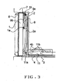
- Figure 3 is a partial side view illustrating a display panel driving mechanism for an electronic device, which is a second embodiment of the present invention, with seeing through some members.
- subslider support shafts 4b and 4b which are installed in a standing manner in the slider 4 go through guide grooves 11b and 11b of a subslider 11, and the subslider 11 is supported movably by the slider 4.
- a first shaft 11a installed in a standing manner in the subslider 11 rotatably supports the lower portion of the display panel 1.
- the slider 4 is driven forward integrally with the subslider 11 from a position illustrated in Figure 3. In the position illustrated in Figure 3, the slider 4 can drive backward the subslider 11 by a driving mechanism which is not illustrated.
- Other construction is the same as that in the first embodiment.
- the same reference numerals are assigned to members which have the same functions as those in the first embodiment, and their detailed description will be omitted.
Landscapes
- Engineering & Computer Science (AREA)
- General Engineering & Computer Science (AREA)
- Theoretical Computer Science (AREA)
- Mechanical Engineering (AREA)
- Computer Hardware Design (AREA)
- Human Computer Interaction (AREA)
- Physics & Mathematics (AREA)
- General Physics & Mathematics (AREA)
- Fittings On The Vehicle Exterior For Carrying Loads, And Devices For Holding Or Mounting Articles (AREA)
- Devices For Indicating Variable Information By Combining Individual Elements (AREA)
- Instrument Panels (AREA)
Abstract
Description
- The present invention relates to a display panel driving mechanism for an electronic device, and in particular, relates to a display panel driving mechanism suitable for a vehicle-mounted electronic device.
- An example of a conventional display panel driving mechanism for a vehicle-mounted electronic device will be described with reference to Figure 4. A chassis, which is not illustrated, and a
subpanel 2 are fixed to a case 3 of a vehicle-mounted electronic device illustrated in Figure 4, and the case 3 of the vehicle-mounted electronic device is attached to a vehicle so that a front plane of thesubpanel 2 may abut on acluster panel 7 of the vehicle. - A
slider 12 driven by a driving mechanism which is not illustrated is attached to the chassis movably in to and fro directions (left and right directions to the figure). A lower portion of the display panel 1 is rotatably supported by ashaft 12a installed in a standing manner in theslider 12, and ashaft 1a fixed to an upper portion of the display panel 1 is engaged with aguide groove 2a provided in thesubpanel 2. - A display unit 8, such as an LCD, is attached to the display panel 1. When the
slider 12 is driven forward, theshaft 12a moves forward with theslider 12, and the lower portion of the display panel 1 moves forward (left direction to the figure). Then, theshaft 1a of the upper portion of the display panel 1 is guided by theguide groove 2a to move downward. - That is, the display panel 1 inclines so that its lower portion may protrude, and releases a recording medium insert port provided in the
subpanel 2 to enable to load and unload a recording medium. Since a front plane of the display unit 8 faces upward in this status, crew can see the display unit 8, and can use the vehicle-mounted electronic device. - In the conventional display panel driving mechanism described above, it is driven so that the lower portion of the display panel 1 may protrude, and it is inclined so that the front plane of the display panel 1 may face upward. However, it is not inclined so that the front plane of the display panel 1 may face downward. When a vehicle-mounted electronic device is arranged horizontally in crew's front lower part, a display plane of the display panel 1 becomes easy-to-see by its inclining so that the front plane may face upward, but the vehicle-mounted electronic device is not necessarily attached to a vehicle in such a position and a posture.
- For example, there are a case that a vehicle-mounted electronic device is attached above crew's eye level, and a case that a vehicle-mounted electronic device is attached in inclination. In these cases, it is required to make the display plane of the display panel 1 be in an easy-to-see posture, or to incline the front plane of the display panel 1 downward so as to avoid reflection of sunlight.
- In the conventional display panel driving mechanism, a
lower end plane 1b of the display panel 1 interferes with alower corner 2b of an aperture portion of thesubpanel 2 when the front plane of the display panel 1 is declined so as to face downward by moving theslider 12 backward in a status illustrated in Figure 4. In addition, in some having a narrow aperture portion of thecluster panel 7, there is a possibility of stacking owing to thelower end plane 1b of the display panel 1 interfering with thecluster panel 7. - Although a vehicle-mounted electronic device accommodation box proposed in
Japanese Patent Application Laid-Open No. 7-285390 - The present invention is made in view of such respects, and aims at providing a display panel driving mechanism for an electronic device which can enlarge sizes of a display plane of a display panel, can incline a front plane of a display panel 1 so as to face downward without providing a large space below the display panel, and can prevent securely interference with a cluster panel of the vehicle and the like when the display panel is driven.
- A display panel driving mechanism for an electronic device according to this invention is a display panel driving mechanism for an electronic device which supports a lower side of a display panel, which is arranged on a front plane of the electronic device, rotatably around a first shaft which moves by following a slider driven in to and fro directions.
The mechanism shifts a second shaft, which is directly installed in a standing manner on an upper side of the display panel or is provided on a member attached on the upper side of the display panel, along a guide groove provided on a member fixed to a case. It is constructed such that the first shaft is shifted backward and upward in a shifting initial period of the first shaft when the first shaft is shifted backward from an initial status, in which the display panel is at a position where it covers the front plane of the electronic device by not inclining, and the front plane of the display panel is inclined downward. - In addition, in the display panel driving mechanism for an electronic device, the member attached on an upper side of the display panel is a lever which is rotatably supported by the display panel. A rotation range of the lever to the display panel is restricted by a part of the lever abutting on the display panel. A second shaft is installed in a standing manner in the lever.
- In addition, in the display panel driving mechanism for each electronic device, the slider and the first shaft are movable also in a forward direction from an initial status in which the display panel is at a position where it covers the front plane of the electronic device by not inclining. Hence, this enables to move the slider forward to make the display panel incline so that a front plane may face upward.
- Furthermore, in the display panel driving mechanism for each electronic device, the first shaft is installed in a standing manner in an arm which is rotatably supported by the slider. It is constructed so that a cam follower provided in the arm may slidably contact with a cam fixed to the case.
- Moreover, in the display panel driving mechanism for an electronic device, the cam follower is energized in a direction of press-contacting with the cam by a spring around the shaft where the arm is supported rotatably. A stopper which restricts rotation of the lever when the cam follower separates from the cam in connection with forward movement of the slider is provided in the slider.
- In addition, in the display panel driving mechanism for an electronic device described above, while a subslider is supported by the slider, the first shaft is installed in a standing manner in the subslider. The above-mentioned subslider is constructed so as to be shifted to the slider so as to shift the first shaft backward and upward from an initial status in which the display panel is at a position where it covers the front plane of the electronic device by not inclining.
- According to the display panel driving mechanism of this invention, since a front plane of a display panel can be inclined so as to face downward, a display plane can be made into an easy-to-see posture regardless of an attached location and a posture of a vehicle-mounted electronic device. Moreover, sizes of the display plane of the display panel can be increased without providing a large space in the lower side of the display panel, which gives it good appearance.
- Furthermore, even when an aperture portion of a cluster panel is narrow, interference with the cluster panel of a vehicle and the like is surely prevented when the display panel is driven.
-
- Figure 1 is a partial side view illustrating a display panel driving mechanism for an electronic device, which is a first embodiment of this invention, with seeing through some members;
- Figure 2 is a partial side view illustrating member movement loci at the time of a display panel drive operation of this display panel driving mechanism in the display panel driving mechanism;
- Figure 3 is a partial side view illustrating a display panel driving mechanism for an electronic device, which is a second embodiment of the present invention, with seeing through some members; and
- Figure 4 is a partial side view illustrating member movement loci with seeing through some members of a conventional display panel driving mechanism for an electronic device.
- Best modes for carrying out this invention will be described below on the basis of embodiments.
- Figure 1 is a partial side view illustrating a display panel driving mechanism for an electronic device, which is a first embodiment of the present invention, with seeing through some members. A chassis, which is not illustrated, and a
subpanel 2 are fixed to a case 3 of a vehicle-mounted electronic device illustrated in Figure 1, and the case 3 of the vehicle-mounted electronic device is attached to a vehicle so that a front plane of thesubpanel 2 may abut on acluster panel 7 of the vehicle. - A slider 4 is attached to the chassis movably in to and fro directions (left and right directions to the figure). The slider 4 is driven in to and fro directions by a driving mechanism which is not illustrated. An arm
rotation center shaft 4a installed in a standing manner in the slider 4 supports an arm 5 rotatably. - A
first shaft 5a installed in a standing manner in one side of the arm 5 supports a lower portion of the display panel 1 rotatably. Aroller 5b rotatably supported by a shaft installed in a standing manner in the other side of the arm 5 is press-contacted with acam 6a provided in a roller guide fixed to the chassis. - That is, the arm 5 is counterclockwise energized by a spring which is not illustrated. A stopper which restricts rotation of the arm 5 when the
roller 5b separates from thecam 6a, and which is not illustrated is provided in the slider 4. - A lever 9 is rotatably supported by the
shaft 1a installed in a standing manner in the display panel 1. Asecond shaft 9a installed in a standing manner in the lever 9 supports theroller 10 rotatably. Theroller 10 is engaged into theguide groove 2a provided in thesubpanel 2. Since a foldedpiece 9b of the lever 9 is enabled to abut on the display panel 1, a rotation range of the lever 9 to the display panel 1 is restricted. - The slider 4, the
guide grooves 2a, the arms 5, the levers 9, and thefirst shafts 9a are provided in both side portions of the display panel 1 symmetrically. In addition, the sliders 4 in both sides have integral construction. The display unit 8, such as an LCD, is attached to the display panel 1. - An action of the display panel driving mechanism with the construction will be described. A slider 4 is driven forward and backward with a position, illustrated in Figure 1, as an initial status. Figure 2 illustrates loci of the display panel 1 at the time of the slider 4 being driven to the rear from the position illustrated in Figure 1.
- As shown in Figure 2, although the
roller 5b moves backward with backward movement of the slider 4, theroller 5b is press-contacted with thecam 6a, and hence, thefirst shaft 5a moves upward with the backward movement of the slider 4 while moving backward. Although an upward force acts on the display panel 1 at this time, thesecond shaft 9a is located in an upper edge of theguide groove 2a, and does not move. - Then, the display panel 1 rotates around the
shaft 1a. Then, the lever 9 rotates clockwise with thesecond shaft 9a as a rotation center. The front plane of the display panel 1 can be inclined downward by such movement. At this time, since thefirst shaft 5a moves upward while moving backward, it is prevented that a lower end plane of the display panel approaches thecluster panel 7, or is stacked by interfering with thecluster panel 7. - When the slider 4 is driven forward from the position illustrated in Figure 1, the
first shaft 5a moves downward with the forward movement of the slider 4 while moving forward. Hence, it is prevented that a top portion of the display panel approaches thecluster panel 7, or is stacked by interfering with thecluster panel 7. When the slider 4 advances further even after theroller 5b and thecam 6a separate, the arm 5 abuts on the stopper of the slider, and rotation is stopped. - When the lower portion of the display panel 1 moves forward greatly, the folded
piece 9b of the lever 9 abuts on the display panel 1, and the lever 9 moves integrally with the display panel 1. Then, thesecond shaft 9a installed in a standing manner in the lever 9 is guided by theguide groove 2a to move downward greatly. The display panel 1 inclined in this manner releases the recording medium insert port provided in thesubpanel 2 to enable to load and unload a recording medium. - Although the embodiment is constructed as described above, the invention is not limited to this, and when making the
cam 6a, which restricts upward movement of theroller 5b of the arm 5, into a grooved shape which also restricts downward movement of theroller 5b, the spring which energizes the arm 5 becomes unnecessary. - Figure 3 is a partial side view illustrating a display panel driving mechanism for an electronic device, which is a second embodiment of the present invention, with seeing through some members. In this example,
subslider support shafts guide grooves - A
first shaft 11a installed in a standing manner in the subslider 11 rotatably supports the lower portion of the display panel 1. The slider 4 is driven forward integrally with the subslider 11 from a position illustrated in Figure 3. In the position illustrated in Figure 3, the slider 4 can drive backward the subslider 11 by a driving mechanism which is not illustrated. Other construction is the same as that in the first embodiment. The same reference numerals are assigned to members which have the same functions as those in the first embodiment, and their detailed description will be omitted. - In this example, when the subslider 11 is driven backward to the slider 4, the
first shaft 11a moves upward while moving backward. Hence, it is prevented that a lower end plane of the display panel approaches thecluster panel 7, or is stacked by interfering with thecluster panel 7. In addition, a front plane of the display panel 1 can be inclined downward by such movement.
Claims (6)
- A display panel driving mechanism for an electronic device which supports a lower side of a display panel, which is arranged on a front plane of the electronic device, rotatably around a first shaft which moves by following a slider driven in to and fro directions, and shifts a second shaft, which is directly installed in a standing manner on an upper side of the display panel or is provided on a member attached on the upper side of the display panel, along a guide groove provided on a member fixed to a case, wherein the first shaft is shifted backward and upward in a shifting initial period of the first shaft when the first shaft is shifted backward from an initial status, in which the display panel is at a position where it covers the front plane of the electronic device by not inclining, and the front plane of the display panel is inclined downward.
- The display panel driving mechanism for an electronic device according to claim 1, wherein the member attached on the upper side of the display panel is a lever which is rotatably supported by the display panel, a rotation range of the lever to the display panel is restricted by a part of the lever abutting on the display panel, and a second shaft is installed in a standing manner in the lever.
- The display panel driving mechanism according to claim 1 or 2, wherein the slider and the first shaft are movable also in a forward direction from an initial status in which the display panel is at a position where it covers the front plane of the electronic device by not inclining, and it is made possible to shift the slider forward to make the display panel incline so that a front plane may face upward.
- The display panel driving mechanism according to one of claims 1 to 3, wherein the first shaft is installed in a standing manner in an arm which is rotatably supported by the slider, and a cam follower provided in the arm may slidably contact with a cam fixed to a case.
- The display panel driving mechanism according to claim 4, wherein the cam follower is energized in a direction of press-contacting with the cam by a spring around a shaft where the arm is supported rotatably, and a stopper which restricts rotation of the lever when the cam follower separates from the cam in connection with forward movement of the slider is provided in the slider.
- The display panel driving mechanism according to one of claims 1 to 3, wherein the first shaft is installed in a standing manner in a subslider while the subslider is supported by the slider, and the subslider is shifted to the slider so as to shift the first shaft backward and upward from an initial status in which the display panel is at a position where it covers the front plane of the electronic device by not inclining.
Applications Claiming Priority (2)
| Application Number | Priority Date | Filing Date | Title |
|---|---|---|---|
| JP2004315204A JP4334457B2 (en) | 2004-10-29 | 2004-10-29 | Electronic device display panel drive mechanism |
| PCT/JP2005/012976 WO2006046332A1 (en) | 2004-10-29 | 2005-07-07 | Display panel driving mechanism for electronic device |
Publications (3)
| Publication Number | Publication Date |
|---|---|
| EP1810886A1 true EP1810886A1 (en) | 2007-07-25 |
| EP1810886A4 EP1810886A4 (en) | 2012-08-29 |
| EP1810886B1 EP1810886B1 (en) | 2014-01-08 |
Family
ID=36227583
Family Applications (1)
| Application Number | Title | Priority Date | Filing Date |
|---|---|---|---|
| EP05760087.6A Expired - Lifetime EP1810886B1 (en) | 2004-10-29 | 2005-07-07 | Display panel driving mechanism for electronic device |
Country Status (6)
| Country | Link |
|---|---|
| US (2) | US8141835B2 (en) |
| EP (1) | EP1810886B1 (en) |
| JP (1) | JP4334457B2 (en) |
| CN (1) | CN101048298B (en) |
| DE (1) | DE05760087T1 (en) |
| WO (1) | WO2006046332A1 (en) |
Families Citing this family (9)
| Publication number | Priority date | Publication date | Assignee | Title |
|---|---|---|---|---|
| US7597290B2 (en) | 2005-03-30 | 2009-10-06 | Fujitsu Ten Limited | Tilting apparatus and electronic apparatus |
| JP2008044429A (en) * | 2006-08-11 | 2008-02-28 | Sanyo Electric Co Ltd | Display device |
| JP4931513B2 (en) * | 2006-08-22 | 2012-05-16 | 三洋電機株式会社 | In-vehicle display device |
| JP2009157165A (en) * | 2007-12-27 | 2009-07-16 | Brother Ind Ltd | Display panel device and electrical equipment |
| JP2010052489A (en) * | 2008-08-26 | 2010-03-11 | Victor Co Of Japan Ltd | Panel attaching/detaching mechanism |
| WO2011092730A1 (en) * | 2010-01-26 | 2011-08-04 | 三菱電機株式会社 | Display apparatus |
| KR101157801B1 (en) * | 2010-09-13 | 2012-06-25 | 풍원공업 주식회사 | door hinge |
| US11072952B2 (en) * | 2019-03-06 | 2021-07-27 | Bsh Home Appliances Corporation | Side opening door keeper |
| CN218895153U (en) * | 2022-04-15 | 2023-04-21 | 东莞市欧姆达汽配有限公司 | Display bracket device |
Family Cites Families (15)
| Publication number | Priority date | Publication date | Assignee | Title |
|---|---|---|---|---|
| US4817240A (en) * | 1983-06-03 | 1989-04-04 | Ace Manufacturing Co. | Appliance door hinge |
| JP2804657B2 (en) | 1991-10-15 | 1998-09-30 | アルパイン株式会社 | Lid opening and closing device |
| JPH07285390A (en) | 1994-04-18 | 1995-10-31 | Sumitomo Wiring Syst Ltd | On-vehicle electronic apparatus storage box |
| DE29811584U1 (en) * | 1998-07-01 | 1999-11-18 | Robert Bosch Gmbh, 70469 Stuttgart | Electric device |
| JP2000132956A (en) | 1998-10-23 | 2000-05-12 | Pioneer Electronic Corp | Vehicle-mounted equipment |
| JP2002154382A (en) | 2000-11-20 | 2002-05-28 | Fujitsu General Ltd | In-vehicle display mounting device |
| FR2820798B1 (en) * | 2001-02-15 | 2003-06-13 | Sagem | TRAVEL SYSTEM FOR MOVING A PANEL FOR REAR PASSENGERS OF A VEHICLE |
| JP4671086B2 (en) | 2001-04-20 | 2011-04-13 | ソニー株式会社 | Electronic equipment with panel body |
| KR100868990B1 (en) | 2001-04-20 | 2008-11-17 | 소니 가부시끼 가이샤 | Electronic device with panel |
| JP2003069920A (en) | 2001-08-29 | 2003-03-07 | Kenwood Corp | Panel device |
| CN2504142Y (en) * | 2001-09-21 | 2002-08-07 | 李万顶 | Positioning device for roof-mounted LCD screen |
| NL1019821C2 (en) * | 2002-01-23 | 2003-07-30 | Vogel S Holding Bv | Device for tiltably mounting a screen on a wall. |
| US6923413B2 (en) * | 2002-04-26 | 2005-08-02 | Premier Mounts | Mounting device for a flat screen display panel |
| KR100461184B1 (en) * | 2002-05-28 | 2004-12-13 | 삼성전자주식회사 | Display |
| CN2618819Y (en) * | 2003-04-18 | 2004-06-02 | 周晓枫 | collectible display device |
-
2004
- 2004-10-29 JP JP2004315204A patent/JP4334457B2/en not_active Expired - Lifetime
-
2005
- 2005-07-07 DE DE05760087T patent/DE05760087T1/en active Pending
- 2005-07-07 EP EP05760087.6A patent/EP1810886B1/en not_active Expired - Lifetime
- 2005-07-07 WO PCT/JP2005/012976 patent/WO2006046332A1/en not_active Ceased
- 2005-07-07 CN CN2005800370493A patent/CN101048298B/en not_active Expired - Lifetime
- 2005-07-07 US US11/666,101 patent/US8141835B2/en active Active
-
2011
- 2011-07-26 US US13/190,612 patent/US8157232B2/en not_active Expired - Lifetime
Also Published As
| Publication number | Publication date |
|---|---|
| CN101048298A (en) | 2007-10-03 |
| WO2006046332A1 (en) | 2006-05-04 |
| US8157232B2 (en) | 2012-04-17 |
| EP1810886A4 (en) | 2012-08-29 |
| CN101048298B (en) | 2010-12-08 |
| EP1810886B1 (en) | 2014-01-08 |
| US20110278413A1 (en) | 2011-11-17 |
| US8141835B2 (en) | 2012-03-27 |
| US20080094382A1 (en) | 2008-04-24 |
| JP4334457B2 (en) | 2009-09-30 |
| JP2006123751A (en) | 2006-05-18 |
| DE05760087T1 (en) | 2008-01-03 |
Similar Documents
| Publication | Publication Date | Title |
|---|---|---|
| US8157232B2 (en) | Display panel driving mechanism for electronic device | |
| EP1564074B1 (en) | Electronic apparatus | |
| JP2014226961A (en) | Display device | |
| JP2007176482A (en) | Device for holding the input / output unit movably | |
| US20020176235A1 (en) | Electronic apparatus | |
| JP2002254930A (en) | Sunroof equipment | |
| EP1977921A1 (en) | Sunshade Apparatus For Vehicle | |
| CN100551730C (en) | sun visor device | |
| JP2010241358A (en) | Back board of vehicle seat | |
| JP3533557B2 (en) | Sunshade device for vehicles | |
| JP2934404B2 (en) | Electronics | |
| JP7095475B2 (en) | Display panel drive mechanism, display unit, and electronic devices | |
| KR102505746B1 (en) | Head up display appratus for vehicle | |
| JP2007106296A (en) | Opening and closing device for front panel of automotive electronic equipment | |
| JP3820324B2 (en) | Front panel device for in-vehicle equipment | |
| JP4416623B2 (en) | Electronic device display panel opening and closing mechanism | |
| JP6954129B2 (en) | Display panel drive mechanism, display unit, and electronic devices | |
| JP4506373B2 (en) | Sun visor equipment | |
| JP6816579B2 (en) | How to move electronic devices and display panels | |
| JP2018157031A (en) | Display panel drive mechanism, display unit, and electronic device | |
| JP2001132309A (en) | Panel switchgear | |
| JP2001132313A (en) | Panel switchgear | |
| JP6984411B2 (en) | Display panel drive mechanism and electronic equipment | |
| JP2022053414A (en) | Display panel drive mechanism and display unit | |
| JP2018177118A (en) | Automotive display device |
Legal Events
| Date | Code | Title | Description |
|---|---|---|---|
| PUAI | Public reference made under article 153(3) epc to a published international application that has entered the european phase |
Free format text: ORIGINAL CODE: 0009012 |
|
| 17P | Request for examination filed |
Effective date: 20070412 |
|
| AK | Designated contracting states |
Kind code of ref document: A1 Designated state(s): DE FR GB |
|
| EL | Fr: translation of claims filed | ||
| RBV | Designated contracting states (corrected) |
Designated state(s): DE FR GB |
|
| DET | De: translation of patent claims | ||
| DAX | Request for extension of the european patent (deleted) | ||
| RAP1 | Party data changed (applicant data changed or rights of an application transferred) |
Owner name: JVC KENWOOD CORPORATION |
|
| A4 | Supplementary search report drawn up and despatched |
Effective date: 20120731 |
|
| RIC1 | Information provided on ipc code assigned before grant |
Ipc: H04N 5/64 20060101ALI20120725BHEP Ipc: B60R 11/02 20060101AFI20120725BHEP Ipc: G09F 9/00 20060101ALI20120725BHEP |
|
| GRAP | Despatch of communication of intention to grant a patent |
Free format text: ORIGINAL CODE: EPIDOSNIGR1 |
|
| INTG | Intention to grant announced |
Effective date: 20130905 |
|
| GRAS | Grant fee paid |
Free format text: ORIGINAL CODE: EPIDOSNIGR3 |
|
| GRAA | (expected) grant |
Free format text: ORIGINAL CODE: 0009210 |
|
| AK | Designated contracting states |
Kind code of ref document: B1 Designated state(s): DE FR GB |
|
| REG | Reference to a national code |
Ref country code: GB Ref legal event code: FG4D |
|
| REG | Reference to a national code |
Ref country code: DE Ref legal event code: R096 Ref document number: 602005042429 Country of ref document: DE Effective date: 20140213 |
|
| REG | Reference to a national code |
Ref country code: DE Ref legal event code: R097 Ref document number: 602005042429 Country of ref document: DE |
|
| PLBE | No opposition filed within time limit |
Free format text: ORIGINAL CODE: 0009261 |
|
| STAA | Information on the status of an ep patent application or granted ep patent |
Free format text: STATUS: NO OPPOSITION FILED WITHIN TIME LIMIT |
|
| 26N | No opposition filed |
Effective date: 20141009 |
|
| REG | Reference to a national code |
Ref country code: DE Ref legal event code: R097 Ref document number: 602005042429 Country of ref document: DE Effective date: 20141009 |
|
| REG | Reference to a national code |
Ref country code: FR Ref legal event code: PLFP Year of fee payment: 12 |
|
| REG | Reference to a national code |
Ref country code: FR Ref legal event code: PLFP Year of fee payment: 13 |
|
| REG | Reference to a national code |
Ref country code: FR Ref legal event code: PLFP Year of fee payment: 14 |
|
| PGFP | Annual fee paid to national office [announced via postgrant information from national office to epo] |
Ref country code: GB Payment date: 20240530 Year of fee payment: 20 |
|
| PGFP | Annual fee paid to national office [announced via postgrant information from national office to epo] |
Ref country code: FR Payment date: 20240611 Year of fee payment: 20 |
|
| PGFP | Annual fee paid to national office [announced via postgrant information from national office to epo] |
Ref country code: DE Payment date: 20240529 Year of fee payment: 20 |
|
| REG | Reference to a national code |
Ref country code: DE Ref legal event code: R071 Ref document number: 602005042429 Country of ref document: DE |
|
| REG | Reference to a national code |
Ref country code: GB Ref legal event code: PE20 Expiry date: 20250706 |