EP1810875A2 - Vehicle seat lock - Google Patents
Vehicle seat lock Download PDFInfo
- Publication number
- EP1810875A2 EP1810875A2 EP07100916A EP07100916A EP1810875A2 EP 1810875 A2 EP1810875 A2 EP 1810875A2 EP 07100916 A EP07100916 A EP 07100916A EP 07100916 A EP07100916 A EP 07100916A EP 1810875 A2 EP1810875 A2 EP 1810875A2
- Authority
- EP
- European Patent Office
- Prior art keywords
- hook member
- striker
- engagement
- seat back
- pivot
- Prior art date
- Legal status (The legal status is an assumption and is not a legal conclusion. Google has not performed a legal analysis and makes no representation as to the accuracy of the status listed.)
- Granted
Links
Images


Classifications
-
- B—PERFORMING OPERATIONS; TRANSPORTING
- B60—VEHICLES IN GENERAL
- B60N—SEATS SPECIALLY ADAPTED FOR VEHICLES; VEHICLE PASSENGER ACCOMMODATION NOT OTHERWISE PROVIDED FOR
- B60N2/00—Seats specially adapted for vehicles; Arrangement or mounting of seats in vehicles
- B60N2/24—Seats specially adapted for vehicles; Arrangement or mounting of seats in vehicles for particular purposes or particular vehicles
- B60N2/32—Seats specially adapted for vehicles; Arrangement or mounting of seats in vehicles for particular purposes or particular vehicles convertible for other use
- B60N2/36—Seats specially adapted for vehicles; Arrangement or mounting of seats in vehicles for particular purposes or particular vehicles convertible for other use into a loading platform
- B60N2/366—Seats specially adapted for vehicles; Arrangement or mounting of seats in vehicles for particular purposes or particular vehicles convertible for other use into a loading platform characterised by the locking device
-
- B—PERFORMING OPERATIONS; TRANSPORTING
- B60—VEHICLES IN GENERAL
- B60N—SEATS SPECIALLY ADAPTED FOR VEHICLES; VEHICLE PASSENGER ACCOMMODATION NOT OTHERWISE PROVIDED FOR
- B60N2/00—Seats specially adapted for vehicles; Arrangement or mounting of seats in vehicles
- B60N2/02—Seats specially adapted for vehicles; Arrangement or mounting of seats in vehicles the seat or part thereof being movable, e.g. adjustable
- B60N2/04—Seats specially adapted for vehicles; Arrangement or mounting of seats in vehicles the seat or part thereof being movable, e.g. adjustable the whole seat being movable
- B60N2/06—Seats specially adapted for vehicles; Arrangement or mounting of seats in vehicles the seat or part thereof being movable, e.g. adjustable the whole seat being movable slidable
- B60N2/08—Seats specially adapted for vehicles; Arrangement or mounting of seats in vehicles the seat or part thereof being movable, e.g. adjustable the whole seat being movable slidable characterised by the locking device
Definitions
- the present invention relates to a vehicle seat lock to hold the seat back of a chair in a standing position, the seat back being capable of standing up or falling down.
- JP2003-146126A discloses a vehicle seat lock comprising a hook member mounted to the seat back supported to a vehicle body to stand up and fall down, and an opening lever operated by an operating device at a shoulder of the seat back, the hook member and opening lever being pivotally secured on each pivot between a base plate and a cover plate fixed to the seat back.
- the hook member, the pivot on which the hook member is secured and a spring for forcing the hook member are assembled in place when the base plate is joined to the cover plate. So a number of assembling are gathered in the final step in which the base plate is joined to the cover plate, which makes assembling more complicate to reduce efficiency.
- JP2001-130295A discloses a vehicle seat lock comprising a hook member mounted to the seat back and engagable with a striker of a vehicle body, and an opening lever connected to an operating knob at the seat back. By the operating knob, the opening lever is operated to allow the hook member to disengage from the striker thereby enabling the seat back to move from a standing position to a falling position.
- the structure that is capable of detecting whether or not the hook member engages with the striker is added to make the structure more complicate and increasing its size. It is likely to make it more difficult for the vehicle seat lock to put in a small space of the seat back.
- a rear seat 1 comprises a seat cushion 2 mounted on a body floor, and a seat back 3 which is supported by a hinge shaft (not shown) at the rear end of the seat cushion 2 to enable the seat back 3 to fall down on the seat cushion 2
- a locking assembly 4 is provided below a shoulder part close to a body panel and engages with a metal striker 5 fixed to the body panel to enable the seat back 3 to be held at the first standing position by a solid line and at the second standing position reclined backwards of the first standing position by a dotted line and to enable the seat back 3 to fall down forwards with operation of an operating device 6 in the shoulder part of the seat back 3.
- the striker 5 comprises a base 53 fixed to the body panel facing the side of the seat back 3, and a U-shaped engaging member 54 comprising the first engagement portion 51 and the second engagement portion 52.
- the locking assembly 4 comprises the first metal base member 7 fixed to a seat frame 31 in Fig. 4 in the seat back 3 with a bolt (not shown), and the second metal base member 11 fixed to the side of the first metal member 7 facing an outside.
- the first and second base members 7,11 have striker-engaging grooves 71,111 in which the first and second engagement portions 51,52 of the striker 5 engage forwards when the seat back 3 stands up.
- a hook member 8 containing metal as matrix to engage with the first or second engagement portions 51,52 of the striker 5 to allow the seat back 3 to be held at the first or second standing position, a synthetic-resin opening lever 9 operated by the operating device 6, and a synthetic-resin sensing member 10 movable depending on engagement of the striker 5 and the hook member 8.
- the mounting bracket 43 may be molded together with the first base member 7.
- the operating device 6 may be mounted to the second base member 11.
- a burring 74 that cylindrically projects rearwards or downwards in Fig. 7, from the first fixing portion 73.
- a female thread is formed to engage with the bolt 18.
- the burring 74 of the first fixing portion 73 engages in the engagement hole 113 of the second fixing portion 112.
- the bolt 18 is screwed in the burring 74.
- the second fixing portion 112 is held between a head 181 of the bolt 18 and the first fixing portion 73.
- the first base member 7 is connected to the second base member 11 after the opening lever 9, the sensing member 10 and the bell crank 23 are mounted to the first base member 7 and after the hook member 8 is mounted to the second base member 11.
- Fig. 8 is a vertical sectional view taken along the line VIII-VIII in Fig. 6; Fig. 9 is a horizontal sectional view taken along the line IX-IX; Fig. 10 is an enlarged view of the hook member 8; and Figs. 11-15 are views for showing operation.
- the operating device 6, the bell crank 23, the hook member 8, the opening lever 9 and the sensing member 10 are on the same surface.
- the front of the figures is deemed as “rear side”
- the back is deemed as “front side”.
- the opening lever 9 and sensing member 10 the left side of the figures is deemed as “rear side” and the right side is deemed as "front side”.
- the hook member 8 is molded with synthetic resin on the outer circumferential surface of metal.
- a pivot portion 88 is pivotally secured on the first pivot 12 in the striker-engaging groove 111 of the second base member 11 to enable it to move up and down.
- the pivot portion 88 is forced by the first spring 13 to go down.
- the first pivot 12 is positioned on an extension of movement of the striker 5.
- the first spring 13 has one end 131 which engages with the hook member 8 and the other end 132 which engages with a projection 114 of the second base member 11.
- the first pivot 12 has a larger-diameter portion 121 between the first base member 7 and the second base member 11.
- the hook member 8 has the first engagement groove 81 opening downwards and capable of selectively engaging with the first and second engagement portions 51,52; and the second engagement groove 82 capable of engaging with the first engagement portion 51.
- the first arm 84 having an inclined edge 83 is provided in the hook member 8 and the second arm 85 is provided between the first engagement groove 81 and the second engagement groove 82. From the side of the hook member 8, a protrusion 86 projects towards the cabin.
- the hook member 8 When the hook member 8 disengages from the striker 5 or when the seat back 3 folds down, it is held horizontally in a standby position in Figs. 6 and 11.
- the hook member 8 When the first engagement portion 51 or the second engagement portion 52 of the striker 5 engages in the first engagement groove 81, the hook member 8 is held in an engagement position where it slightly rotates upwards from the standby position in Fig. 12 or 15.
- the hook member 8 rotates in an unlocking direction or a clockwise direction in Figs. 6 and 11-15 to shift to the first-step unlocking position in Fig. 13 in which the first engagement portion 51 is releasable from the first engagement groove 81 only rearwards.
- the hook member 8 rotates upwards from the first-step unlocking position and enables it to shift to the second-step unlocking position in Fig. 14 in which the first engagement portion 51 can engage in the second engagement groove 82 from the first engagement groove 81.
- the first engagement portion 51 of the striker 5 engages in the first engagement groove 81 of the hook member 8, and when it is held in the second standing position, the second engagement portion 52 engages in the first engagement groove 81 and the first engagement portion 51 puts in the second engagement groove 82 with play.
- the first and second arms 84,85 project downwards to put on the inner side surface of the second base member 11, and the lower end of the second arm 85 is allowed to contact the lower surface of the second base member 11 when the hook member 8 is in the standby position.
- the first engagement groove 81 is formed like a wedge to reduce a width upwards gradually.
- a width (W1) is set to put the striker 5 between the engagement portions 51 and 52 without loosening.
- the first engagement groove 81 tightly fits in the first engagement portions 51 and 52 thereby preventing the seat back 3 from moving back and forth.
- a receiving edge 8a of the first engagement groove 81 contacts the first and second engagement portions 51,52 of the striker 5 when the seat back 3 is leaned backwards.
- the second arm 85 which comprises the receiving edge 8a and a contact portion 8b continuous with the receiving edge 8a, metal matrix is exposed without synthetic resin molding.
- the front edge of the first arm 84 comprises the inclined edge 83 of the first arm 84 and a coming-out preventing edge 8c which faces the receiving edge 8a of the first engagement groove 81.
- the coming-out-preventing edge 8e contacts the first and second engagement portions 51,52 when the seat back 3 falls down and folds on the seat.
- the front edge is molded with synthetic resin.
- first or second engagement portion 51 or 52 of the striker 5 engages in the first engagement groove 81 of the hook member 8
- metal parts contacts each other. Even though the hook member 8 is molded with synthetic resin, deformation of synthetic resin over the parts does not prevent the hook member 8 from moving out. Thus, the first engagement portion 51 does not engage in the second engagement groove 82 beyond the first engagement groove 81.
- the metal-exposing receiving edge 8a can receive weight of the leaning seat back 3 when a passenger sits down the rear seat 1. Even though the hook member 8 is molded with synthetic resin, neither fast collapse nor deformation of the synthetic resin is prevented thereby assuring stable engagement of the hook member 8 with the striker 5 for a long time.
- the second engagement groove 82 is formed between the second arm 85 and the pivot portion 88 pivotally supported by the first pivot 12.
- a front edge 85a of the second arm 85 comprises an arc of a circle around the first pivot 12 as a center.
- a buffer portion 87 molded with synthetic resin.
- the front edge 85a of the second arm 85 is formed as an arc of a circle around the first pivot 12 as center.
- the buffer portion 87 is positioned out of the movement track L of the first and second engagement portions 51,52 of the striker 5 when the hook member 8 is in an engagement position in Figs. 12 and 15.
- the buffer portion 87 moves into the movement track L when the hook member 8 shifts to the second-step unlocking position in Fig. 14.
- the first engagement portion 51 comes into the second engagement groove 82 of the hook member 8
- the first engagement portion 51 contacts the buffer portion 87 to restrict invasion of the striker 5 and to reduce noise when the striker 5 comes in.
- the hook member 8 rotates from the second-step unlocking position in a direction of engagement or in an anticlockwise direction in Figs.
- the first engagement groove 81 can surely engage with the second engagement portion 52.
- the buffer portion 87 may preferably be molded with the hook member 8 in synthetic resin. Instead, it may be formed separately from the hook member 8.
- An opening lever 9 is pivoted with the second pivot 14 above the striker-engaging groove 71 of the first base member 7, forced in a standby direction or in a clockwise direction in Figs. 6 and 11-15 by the second spring 15 wound on the second pivot 14 and held in the standby position in which a lower acting portion 91 is positioned downwards in Figs. 6, 11, 12 and 15.
- the acting portion 91 is between the hook member 8 and sensing member 10 and allowed to contact a projection 86 of the hook member 8 when the opening lever 9 rotates anticlockwise from the standby position.
- a certain gap is formed not to contact the acting portion 91 with the projection 86 owing to variation of the mounted positions of the hook member 8, striker 5 and other parts.
- the opening lever 9 rotates anticlockwise from the standby position to the first operating position in Fig. 13 to allow the front edge of the acting portion 91 to contact the projection 86 of the hook member 8 to shift the hook member 8 from the engagement position to the first-step unlocking position.
- the opening lever 9 shifts to the second operating position in Fig. 14 in which it rotates further anticlockwise from the first operating position to allow the hook member 8 to shift to the second-step unlocking position.
- the sensing member 10 is pivotally secured on a third pivot 16 above the striker-engaging groove 71 of the first base member 7; forced by a third spring 17 wound around the third pivot 160; and usually held in the standby position in Figs. 6 and 11 in which the upper front portion contacts a stopper 75 of the first base member 7.
- the sensing member 10 has at the lower rear end a contact portion 101 which can go on the first and second engagement portions 51,52 of the striker 5.
- the first engagement portion 51 or second engagement portion 52 of the striker 5 engages in the first engagement groove 81 of the hook member 8 to allow the contact portion 101 to go on the first or second engagement portion 51 or 52 to enable the sensing member 10 to shift to a detecting position to which the standby position rotates upwards in Figs. 12-15.
- the operating device 6 As described in Fig. 4, the operating device 6 is exposed from the shoulder of the seat back 3 and comprises a rectangular guide member 20 in a mounting hole 431a of the mounting bracket 43 and an operating knob 21 which is stored to enable it to slide in the guide member 20 up and down.
- the operating knob 21 is connected to a connecting shaft 233 fixed to one end of the bell crank 23 and moved with the bell crank 23 between the first rest position A in which the upper surface is substantially coplanar with the upper surface of the guide member 20 in Figs. 12 and 15 and the second rest position in which the upper surface is retracted in Fig. 11. According to the passenger, the upper surface of the operating knob 21 is shifted to the first operating position C in Fig. 13 which is retracted further from the second rest position B and the second operating position D in Fig. 14 which is retracted further from the second operating position C.
- the first or second engagement portion 51 or 52 of the striker 5 engages in the first engagement groove 81 of the hook member and the sensing member 10 is in the detecting position.
- the sensing member 10 is in the standby position and the first and second engagement portions 51,52 disengage from the first engagement groove 81 of the hook member 8.
- the opening lever 9 is moved to the first acting position to allow the hook member 8 to move to the first-step unlocking position.
- the opening lever 9 is moved to the second acting position to allow the hook member 8 to move to the second-step unlocking position.
- an indicator (not shown) comprising a different color from the guide member 20 or letters "UNLOCK".
- the indicator is hindered when the operating knob 21 is in the first rest position A, while it is exposed when the operating knob 21 is out of the first rest position A thereby allowing the passenger to warn that the locking assembly 4 disengages from the striker 5 to improve secutiry.
- the bell crank 23 is pivotally secured on the fourth pivot 22 to the mounting bracket 43 to move up and down, and forced clockwise by a fourth spring 25 wound on the fourth pivot 22 in Figs. 6 and 11-15.
- the bell crank 23 is moved together with the operating knob 21 to the first rest position A1 in Figs. 12 and 15; the second rest position B1 in Fig. 11 to which it rotates anticlockwise from the first rest position AS1; the first operating position C1 in Fig. 13 to which it rotates anticlockwise from the second rest position B1; and the second operating position D1 in Fig. 14 to which it rotates anticlockwise from the first operating position C1.
- the force of the fourth spring 25 acting to the bell crank 23 is set to be smaller than the force of the third spring 17 acting to the sensing member 10.
- the other end of the bell crank 23 has the first elongate opening 231 and second elongate opening 232 extending vertically.
- the upper end 24a of the first connecting rod 24 connected at the lower end to the sensing member 10 engages with play to slide up and down.
- the upper end 26a of the second connecting rod 26 connected at the lower end to the opening lever 9 engages with play to slide up and down.
- the first elongate opening 231 is set to have a length having a play to the upper end 24a of the first connecting rod 24 corresponding to stroke of the bell crank 23 between the first rest position A1 and the second operating position D1 with respect to anticlockwise rotation of the bell crank 23 when the operating knob 21 and bell crank 23 are in the first rest position A, A1.
- motion of the operating knob 21 and bell crank 23 from the first rest position A,A1 to the second operating position D,D1 and vice versa is not transmitted to the sensing member 10.
- the second elongate opening 232 is set to have a length having a play to the upper end 26a of the second connecting rod 26 corresponding to stroke of the bell crank 23 between the first rest position A1 and the second rest position B1 with respect to anticlockwise rotation of the bell crank 23 when the bell crank 23 is in the first rest position A1.
- motion of the operating knob 21 and bell crank 23 from the first rest position A,A1 to the second rest position B,B1 and vice versa is not transmitted to the opening lever 9.
- the operating knob 21 and the bell crank 23 moves from the first rest position A,A1 to the second rest position B,B1 below.
- the sensing member 10 shifts from the detecting position to the standby position, so that the first connecting rod 25 goes up to allow the upper end 24a to contact the upper edge of the first elongate opening 231 to press up the bell crank 23.
- the bell crank 23 shifts to the second rest position B1 against the force of the fourth spring 25.
- the ends of the pivots 14,16 are previously crimped.
- the opening lever 9 and the sensing member 10 are pivotally connected to the first base member 7 with the pivots 14,16 and the springs 15,17 are connected, so that the first subassembly 41 is formed.
- One end of the first pivot 12 or the end which projects from the second base member 11 is crimped and the hook member 8 is pivotally connected to the second base member 11 with the pivot 12. As shown in Figs. 8 and 9, the hook member 8 is put between the second base member 11 and the larger-diameter portion 121 of the first pivot 12 to enable the hook member 8 to rotate.
- first and second subassemblies 41,42 are formed, a positioning projection 76 of the first base member 7 is engaged in a positioning opening 115 of the second base member 11 and positioned. And the other end of the first pivot 12 is put into an axial hole 72 of the first base member 7 and crimped in Fig. 2.
- first fixing portion 73 is joined to the second fixing portion 112 with a bolt 18 in a direction perpendicular to the pivots 12,14,16.
- the first subassembly 41 and the second subassembly 42 are previously formed, which results in efficient assembling of the locking assembly 4.
- the first base member 7 is connected to the second base member 11 with the bolt 18 at an opening side of the striker-engaging grooves 71,111 with the first pivot 12 at the inner part of the striker-engaging grooves 71,111 thereby preventing deformation around the striker-engaging grooves 71,111 in which load is gathered and improving lock strength.
- the hook member 8 is pivotally connected to the second base member 11, and the opening lever 9 and the sensing member 10 are pivotally connected to the first base member 7.
- the hook member 8 and the sensing member 10 are arranged in parallel between the first base member 7 and the second base member 11, thereby shortening height of the locking assembly 4.
- the locking assembly 4 can be disposed in a narrow space close to the shoulder of the seat back 3.
- the locking assembly 4 can be disposed at a position spaced from a hinge shaft at maximum thereby reducing moment acting to the locking assembly 4 and improving support strength of the seat back 3.
- the hook member 8 can be disposed closer to the body panel to which the striker 5 is fixed thereby shortening the length of the engagement portions 51,52 and improving locking strength.
Landscapes
- Engineering & Computer Science (AREA)
- Aviation & Aerospace Engineering (AREA)
- Transportation (AREA)
- Mechanical Engineering (AREA)
- Seats For Vehicles (AREA)
- Lock And Its Accessories (AREA)
Abstract
Description
- The present invention relates to a vehicle seat lock to hold the seat back of a chair in a standing position, the seat back being capable of standing up or falling down.
-
JP2003-146126A - In the vehicle seat back, the hook member, the pivot on which the hook member is secured and a spring for forcing the hook member are assembled in place when the base plate is joined to the cover plate. So a number of assembling are gathered in the final step in which the base plate is joined to the cover plate, which makes assembling more complicate to reduce efficiency.
-
JP2001-130295A - However, in the vehicle seat lock, the structure that is capable of detecting whether or not the hook member engages with the striker is added to make the structure more complicate and increasing its size. It is likely to make it more difficult for the vehicle seat lock to put in a small space of the seat back.
- In view of the disadvantages in the prior art, it is an object of the present invention to provide a vehicle seat lock enabling assembling efficiency to improve.
- It is another object of the present invention to provide a vehicle seat lock allowing it to be simplified and reduced in size.
- The features and advantages of the invention will become more apparent from the following description with respect to embodiments as shown in the accompanying drawings wherein:
- Fig. 1 is a perspective view of a rear seat for a vehicle including the present invention;
- Fig. 2 is an exploded perspective view of a locking assembly;
- Fig. 3 is a rear perspective view of the locking assembly provisionally assembled;
- Fig. 4 is a rear perspective view of the locking assembly;
- Fig. 5 is a side view of the locking assembly;
- Fig. 6 is a side view of the locking assembly;
- Fig. 7 is a horizontal sectional view taken along the line Vll-Vll in Fig. 5;
- Fig. 8 is a vertical sectional view taken along the line VIII-VIII in Fig. 6;
- Fig. 9 is a horizontal sectional view taken along the line IX-IX in Fig. 6;
- Fig. 10 is an enlarged view of a hook member;
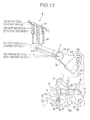
- Fig. 11 is a view showing an action of main parts when an operating knob is in the second rest position;
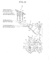
- Fig. 12 is a view showing an action of main parts when the operating knob is in the first rest position;
- Fig. 13 s a view showing an action of main parts when the operating knob is in the first operating position;
- Fig. 14 is a view showing an action of main parts when the operating knob is in the second rest position; and
- Fig. 15 is a view showing an action of main parts when the operating knob is in the first rest position.
- As shown in Fig. 1, a rear seat 1 comprises a seat cushion 2 mounted on a body floor, and a seat back 3 which is supported by a hinge shaft (not shown) at the rear end of the seat cushion 2 to enable the seat back 3 to fall down on the seat cushion 2
- In the seat back 3, a locking assembly 4 is provided below a shoulder part close to a body panel and engages with a
metal striker 5 fixed to the body panel to enable the seat back 3 to be held at the first standing position by a solid line and at the second standing position reclined backwards of the first standing position by a dotted line and to enable the seat back 3 to fall down forwards with operation of an operating device 6 in the shoulder part of the seat back 3. - The
striker 5 comprises abase 53 fixed to the body panel facing the side of the seat back 3, and a U-shapedengaging member 54 comprising thefirst engagement portion 51 and thesecond engagement portion 52. - In Fig. 4, the locking assembly 4 comprises the first
metal base member 7 fixed to aseat frame 31 in Fig. 4 in the seat back 3 with a bolt (not shown), and the secondmetal base member 11 fixed to the side of thefirst metal member 7 facing an outside. The first andsecond base members second engagement portions striker 5 engage forwards when the seat back 3 stands up. - Between the
first base member 7 and thesecond base member 11, there are disposed ahook member 8 containing metal as matrix to engage with the first orsecond engagement portions striker 5 to allow the seat back 3 to be held at the first or second standing position, a synthetic-resin opening lever 9 operated by the operating device 6, and a synthetic-resin sensing member 10 movable depending on engagement of thestriker 5 and thehook member 8. - To a
metal mounting bracket 43 fixed on thefirst base member 7, an operating device 6 and abell crank 23 are mounted. Themounting bracket 43 may be molded together with thefirst base member 7. The operating device 6 may be mounted to thesecond base member 11. - As shown in Fig. 4, above the striker-engagement grooves 71,111 of the first and
second base members first fixing member 73 and thesecond fixing member 112 connected to each other with abolt 18. - As shown in Fig. 7, a burring 74 that cylindrically projects rearwards or downwards in Fig. 7, from the
first fixing portion 73. On the inner circumferential surface of the burring 74, a female thread is formed to engage with thebolt 18. - In the
second fixing portion 112 on the rear surface of thefirst fixing portion 73, there is anengagement hole 113 in which theburring 74 engages. - To connect the
first base member 7 to thesecond base member 11, the burring 74 of thefirst fixing portion 73 engages in theengagement hole 113 of thesecond fixing portion 112. In this condition, thebolt 18 is screwed in the burring 74. As shown in Fig. 7, thesecond fixing portion 112 is held between ahead 181 of thebolt 18 and thefirst fixing portion 73. By connecting opening sides of the striker-engaging grooves 71,111 of the first andsecond base members second base members hook member 8, locking strength of the locking assembly 4 can be improved. - The
first base member 7 is connected to thesecond base member 11 after the opening lever 9, thesensing member 10 and thebell crank 23 are mounted to thefirst base member 7 and after thehook member 8 is mounted to thesecond base member 11. - Fig. 8 is a vertical sectional view taken along the line VIII-VIII in Fig. 6; Fig. 9 is a horizontal sectional view taken along the line IX-IX; Fig. 10 is an enlarged view of the
hook member 8; and Figs. 11-15 are views for showing operation. - In Figs. 11-15, the operating device 6, the
bell crank 23, thehook member 8, the opening lever 9 and thesensing member 10 are on the same surface. Thus, in the operating device 6 and thebell crank 23, the front of the figures is deemed as "rear side", and the back is deemed as "front side". In thehook member 8, the opening lever 9 and sensingmember 10, the left side of the figures is deemed as "rear side" and the right side is deemed as "front side". - The
hook member 8 is molded with synthetic resin on the outer circumferential surface of metal. Apivot portion 88 is pivotally secured on thefirst pivot 12 in the striker-engaging groove 111 of thesecond base member 11 to enable it to move up and down. Thepivot portion 88 is forced by thefirst spring 13 to go down. Thefirst pivot 12 is positioned on an extension of movement of thestriker 5. - As shown in Fig. 6, the
first spring 13 has oneend 131 which engages with thehook member 8 and theother end 132 which engages with aprojection 114 of thesecond base member 11. As shown in Figs. 8 and 9, thefirst pivot 12 has a larger-diameter portion 121 between thefirst base member 7 and thesecond base member 11. - The
hook member 8 has thefirst engagement groove 81 opening downwards and capable of selectively engaging with the first andsecond engagement portions second engagement groove 82 capable of engaging with thefirst engagement portion 51. Thefirst arm 84 having aninclined edge 83 is provided in thehook member 8 and thesecond arm 85 is provided between thefirst engagement groove 81 and thesecond engagement groove 82. From the side of thehook member 8, aprotrusion 86 projects towards the cabin. - When the
hook member 8 disengages from thestriker 5 or when the seat back 3 folds down, it is held horizontally in a standby position in Figs. 6 and 11. When thefirst engagement portion 51 or thesecond engagement portion 52 of thestriker 5 engages in thefirst engagement groove 81, thehook member 8 is held in an engagement position where it slightly rotates upwards from the standby position in Fig. 12 or 15. According to operation of the operating device 6 to the first operating position (C) below, thehook member 8 rotates in an unlocking direction or a clockwise direction in Figs. 6 and 11-15 to shift to the first-step unlocking position in Fig. 13 in which thefirst engagement portion 51 is releasable from thefirst engagement groove 81 only rearwards. - Furthermore, according to operation of the operating device 6 to the second operating position (D) below, the
hook member 8 rotates upwards from the first-step unlocking position and enables it to shift to the second-step unlocking position in Fig. 14 in which thefirst engagement portion 51 can engage in thesecond engagement groove 82 from thefirst engagement groove 81. - When the seat back 3 is held in the first standing position, the
first engagement portion 51 of thestriker 5 engages in thefirst engagement groove 81 of thehook member 8, and when it is held in the second standing position, thesecond engagement portion 52 engages in thefirst engagement groove 81 and thefirst engagement portion 51 puts in thesecond engagement groove 82 with play. - The first and
second arms second base member 11, and the lower end of thesecond arm 85 is allowed to contact the lower surface of thesecond base member 11 when thehook member 8 is in the standby position. - As shown in Fig. 10, the
first engagement groove 81 is formed like a wedge to reduce a width upwards gradually. A width (W1) is set to put thestriker 5 between theengagement portions first engagement groove 81 tightly fits in thefirst engagement portions - A receiving
edge 8a of thefirst engagement groove 81 contacts the first andsecond engagement portions striker 5 when the seat back 3 is leaned backwards. On the rear edge of thesecond arm 85 which comprises the receivingedge 8a and acontact portion 8b continuous with the receivingedge 8a, metal matrix is exposed without synthetic resin molding. - The front edge of the
first arm 84 comprises theinclined edge 83 of thefirst arm 84 and a coming-out preventingedge 8c which faces the receivingedge 8a of thefirst engagement groove 81. The coming-out-preventing edge 8e contacts the first andsecond engagement portions - Immediately before the first or
second engagement portion striker 5 engages in thefirst engagement groove 81 of thehook member 8, metal parts contacts each other. Even though thehook member 8 is molded with synthetic resin, deformation of synthetic resin over the parts does not prevent thehook member 8 from moving out. Thus, thefirst engagement portion 51 does not engage in thesecond engagement groove 82 beyond thefirst engagement groove 81. - When the first and
second engagement portions first engagement groove 81, the metal-exposingreceiving edge 8a can receive weight of the leaning seat back 3 when a passenger sits down the rear seat 1. Even though thehook member 8 is molded with synthetic resin, neither fast collapse nor deformation of the synthetic resin is prevented thereby assuring stable engagement of thehook member 8 with thestriker 5 for a long time. - When the passenger leans against the seat back 3 or when weight is applied to the seat cushion 2, one needs to operate an operating
knob 21. Load can be received by the receivingedge 8a of thehook member 8, so that thehook member 8 is unlikely to rotate in an unlocking direction without deformation of synthetic resin. Synthetic resin is not applied to the rear edge or the receivingedge 8a andcontact portion 8b of thesecond arm 85. Thus, when the operatingknob 21 is operated, synthetic resin is not caught to decrease the change in operation ensuring suitable operation. - When the first and
second engagement portions striker 5 goes into the striker-engaging grooves 71,111 to contact theinclined edge 83 of thehook member 8, noise is relieved with the synthetic resin part. - The
second engagement groove 82 is formed between thesecond arm 85 and thepivot portion 88 pivotally supported by thefirst pivot 12. When thefirst engagement portion 51 of thestriker 5 engages in thesecond engagement groove 82 in the second standing position of the seat back 3, the width is determined not to allow thefirst engagement portion 51 to engage with thesecond engagement groove 82. - A
front edge 85a of thesecond arm 85 comprises an arc of a circle around thefirst pivot 12 as a center. At the rear edge of thepivot portion 88, there is formed abuffer portion 87 molded with synthetic resin. - The
front edge 85a of thesecond arm 85 is formed as an arc of a circle around thefirst pivot 12 as center. When the seat back 3 is held in the second standing position, forward excessive load acts to the seat back 3 via a seat belt connected to the seat back 3. Even if thesecond engagement portion 52 is deformed to go out of thefirst engagement groove 81, thefirst engagement portion 51 contacts thefront edge 85a of thesecond arm 85 in a substantially perpendicular direction, so that thefirst engagement portion 51 neither press up thesecond arm 85 nor rotates thehook member 8 in an unlocking direction. Thus, the present invention affects locking strength even in engagement relationship of thefirst engagement portion 51 and thesecond engagement portion 82, so that the seat back 3 can be held firmly in the second standing position. - The
buffer portion 87 is positioned out of the movement track L of the first andsecond engagement portions striker 5 when thehook member 8 is in an engagement position in Figs. 12 and 15. Thebuffer portion 87 moves into the movement track L when thehook member 8 shifts to the second-step unlocking position in Fig. 14. Thus, when thefirst engagement portion 51 comes into thesecond engagement groove 82 of thehook member 8, thefirst engagement portion 51 contacts thebuffer portion 87 to restrict invasion of thestriker 5 and to reduce noise when thestriker 5 comes in. Thehook member 8 rotates from the second-step unlocking position in a direction of engagement or in an anticlockwise direction in Figs. 6 and 11-15 to shift to the engagement position to allow thebuffer portion 87 to shift out of the movement track L to go away from thefirst engagement portion 51. Without subjecting to variation in distance between thefirst engagement portion 51 and thesecond engagement portion 52 of thestriker 5 or to errors in a mounted position of the locking assembly 4, thefirst engagement groove 81 can surely engage with thesecond engagement portion 52. - The
buffer portion 87 may preferably be molded with thehook member 8 in synthetic resin. Instead, it may be formed separately from thehook member 8. - An opening lever 9 is pivoted with the
second pivot 14 above the striker-engaginggroove 71 of thefirst base member 7, forced in a standby direction or in a clockwise direction in Figs. 6 and 11-15 by thesecond spring 15 wound on thesecond pivot 14 and held in the standby position in which alower acting portion 91 is positioned downwards in Figs. 6, 11, 12 and 15. - The acting
portion 91 is between thehook member 8 and sensingmember 10 and allowed to contact aprojection 86 of thehook member 8 when the opening lever 9 rotates anticlockwise from the standby position. When the opening lever 9 is in the standby position, a certain gap is formed not to contact the actingportion 91 with theprojection 86 owing to variation of the mounted positions of thehook member 8,striker 5 and other parts. - As mentioned below, based on the operating
knob 21 of the operating device 6, the opening lever 9 rotates anticlockwise from the standby position to the first operating position in Fig. 13 to allow the front edge of the actingportion 91 to contact theprojection 86 of thehook member 8 to shift thehook member 8 from the engagement position to the first-step unlocking position. The opening lever 9 shifts to the second operating position in Fig. 14 in which it rotates further anticlockwise from the first operating position to allow thehook member 8 to shift to the second-step unlocking position. - The sensing
member 10 is pivotally secured on athird pivot 16 above the striker-engaginggroove 71 of thefirst base member 7; forced by a third spring 17 wound around the third pivot 160; and usually held in the standby position in Figs. 6 and 11 in which the upper front portion contacts astopper 75 of thefirst base member 7. - The sensing
member 10 has at the lower rear end acontact portion 101 which can go on the first andsecond engagement portions striker 5. - The
first engagement portion 51 orsecond engagement portion 52 of thestriker 5 engages in thefirst engagement groove 81 of thehook member 8 to allow thecontact portion 101 to go on the first orsecond engagement portion member 10 to shift to a detecting position to which the standby position rotates upwards in Figs. 12-15. - Then, the operating device 6 will be described. As described in Fig. 4, the operating device 6 is exposed from the shoulder of the seat back 3 and comprises a
rectangular guide member 20 in a mountinghole 431a of the mountingbracket 43 and an operatingknob 21 which is stored to enable it to slide in theguide member 20 up and down. - The operating
knob 21 is connected to a connectingshaft 233 fixed to one end of the bell crank 23 and moved with the bell crank 23 between the first rest position A in which the upper surface is substantially coplanar with the upper surface of theguide member 20 in Figs. 12 and 15 and the second rest position in which the upper surface is retracted in Fig. 11. According to the passenger, the upper surface of the operatingknob 21 is shifted to the first operating position C in Fig. 13 which is retracted further from the second rest position B and the second operating position D in Fig. 14 which is retracted further from the second operating position C. - In the first rest position A, the first or
second engagement portion striker 5 engages in thefirst engagement groove 81 of the hook member and the sensingmember 10 is in the detecting position. In the second rest position B, the sensingmember 10 is in the standby position and the first andsecond engagement portions first engagement groove 81 of thehook member 8. In the first operating position C, the opening lever 9 is moved to the first acting position to allow thehook member 8 to move to the first-step unlocking position. In the second operating position D, the opening lever 9 is moved to the second acting position to allow thehook member 8 to move to the second-step unlocking position. - On the upper inner circumferential surface of the
guide member 20, there is an indicator (not shown) comprising a different color from theguide member 20 or letters "UNLOCK". The indicator is hindered when the operatingknob 21 is in the first rest position A, while it is exposed when the operatingknob 21 is out of the first rest position A thereby allowing the passenger to warn that the locking assembly 4 disengages from thestriker 5 to improve secutiry. - The
bell crank 23 is pivotally secured on thefourth pivot 22 to the mountingbracket 43 to move up and down, and forced clockwise by afourth spring 25 wound on thefourth pivot 22 in Figs. 6 and 11-15. Thebell crank 23 is moved together with the operatingknob 21 to the first rest position A1 in Figs. 12 and 15; the second rest position B1 in Fig. 11 to which it rotates anticlockwise from the first rest position AS1; the first operating position C1 in Fig. 13 to which it rotates anticlockwise from the second rest position B1; and the second operating position D1 in Fig. 14 to which it rotates anticlockwise from the first operating position C1. - The force of the
fourth spring 25 acting to the bell crank 23 is set to be smaller than the force of the third spring 17 acting to the sensingmember 10. - The other end of the bell crank 23 has the first
elongate opening 231 and secondelongate opening 232 extending vertically. - In the first
elongate opening 231, theupper end 24a of the first connectingrod 24 connected at the lower end to the sensingmember 10 engages with play to slide up and down. In the secondelongate opening 232, theupper end 26a of the second connectingrod 26 connected at the lower end to the opening lever 9 engages with play to slide up and down. - The first
elongate opening 231 is set to have a length having a play to theupper end 24a of the first connectingrod 24 corresponding to stroke of the bell crank 23 between the first rest position A1 and the second operating position D1 with respect to anticlockwise rotation of the bell crank 23 when the operatingknob 21 and bell crank 23 are in the first rest position A, A1. Thus, motion of the operatingknob 21 and bell crank 23 from the first rest position A,A1 to the second operating position D,D1 and vice versa is not transmitted to the sensingmember 10. - The second
elongate opening 232 is set to have a length having a play to theupper end 26a of the second connectingrod 26 corresponding to stroke of the bell crank 23 between the first rest position A1 and the second rest position B1 with respect to anticlockwise rotation of the bell crank 23 when the bell crank 23 is in the first rest position A1. Thus, motion of the operatingknob 21 and bell crank 23 from the first rest position A,A1 to the second rest position B,B1 and vice versa is not transmitted to the opening lever 9. - The operating
knob 21 and the bell crank 23 moves from the first rest position A,A1 to the second rest position B,B1 below. - When the sensing
member 10 is in the standby position in Fig. 11:
While theupper end 24a of the first connectingrod 24 contacts the upper end of the firstelongate opening 231, the operatingknob 21 and bell crank 23 are held in the second rest position B,B1. In this case, force of the third spring 17 acting to the sensingmember 10 is set to be greater than force of thefourth spring 25 acting to the bell crank 23, so that the bell crank 23 does not rotate clockwise or in the first rest position A1 by the force of thefourth spring 25. - When the sensing
member 10 shifts from the standby position to the detecting position from Fig. 11 to Fig. 12 or 15:
The sensingmember 10 shifts from the detecting position to the standby position, so that the first connectingrod 24 goes down. Following the motion of the sensingmember 10, the bell crank 23 shifts by the force of thefourth spring 25 from the second rest position B1 to the first rest position A1. - When the sensing
member 10 shifts from the detecting position to the standby position in Fig. 12 or 15 to Fig. 11 - The sensing
member 10 shifts from the detecting position to the standby position, so that the first connectingrod 25 goes up to allow theupper end 24a to contact the upper edge of the firstelongate opening 231 to press up thebell crank 23. Thus, the bell crank 23 shifts to the second rest position B1 against the force of thefourth spring 25. - Then, it will be described how to assemble the locking assembly 4. As shown in Fig. 3, before the
first base member 7 is connected to thesecond base member 11, thefirst subassembly 41 for thefirst base member 7 and thesecond subassembly 42 for thesecond base member 11 are formed. - The ends of the
pivots member 10 are pivotally connected to thefirst base member 7 with thepivots springs 15,17 are connected, so that thefirst subassembly 41 is formed. - One end of the
first pivot 12 or the end which projects from thesecond base member 11 is crimped and thehook member 8 is pivotally connected to thesecond base member 11 with thepivot 12. As shown in Figs. 8 and 9, thehook member 8 is put between thesecond base member 11 and the larger-diameter portion 121 of thefirst pivot 12 to enable thehook member 8 to rotate. - After the first and
second subassemblies positioning projection 76 of thefirst base member 7 is engaged in apositioning opening 115 of thesecond base member 11 and positioned. And the other end of thefirst pivot 12 is put into anaxial hole 72 of thefirst base member 7 and crimped in Fig. 2. As mentioned above, the first fixingportion 73 is joined to thesecond fixing portion 112 with abolt 18 in a direction perpendicular to thepivots first subassembly 41 and thesecond subassembly 42 are previously formed, which results in efficient assembling of the locking assembly 4. - The
first base member 7 is connected to thesecond base member 11 with thebolt 18 at an opening side of the striker-engaging grooves 71,111 with thefirst pivot 12 at the inner part of the striker-engaging grooves 71,111 thereby preventing deformation around the striker-engaging grooves 71,111 in which load is gathered and improving lock strength. - The
hook member 8 is pivotally connected to thesecond base member 11, and the opening lever 9 and the sensingmember 10 are pivotally connected to thefirst base member 7. Thus, thehook member 8 and the sensingmember 10 are arranged in parallel between thefirst base member 7 and thesecond base member 11, thereby shortening height of the locking assembly 4. As a result, the locking assembly 4 can be disposed in a narrow space close to the shoulder of the seat back 3. Thus, the locking assembly 4 can be disposed at a position spaced from a hinge shaft at maximum thereby reducing moment acting to the locking assembly 4 and improving support strength of the seat back 3. - The
hook member 8 can be disposed closer to the body panel to which thestriker 5 is fixed thereby shortening the length of theengagement portions - The function of the present embodiment will be described:
- (i) When the seat back 3 is held in the first standing position in Fig. 12:
Thefirst engagement portion 51 of thestriker 5 engages in thefirst engagement groove 81 of thehook member 8, In this condition, thefirst engagement portion 51 contacts the receivingedge 8a of thehook member 8.
Thecontact portion 101 of the sensingmember 10 rides on thefirst engagement portion 51 of thestriker 5 to move the detecting position. Thus, the operatingknob 21 is held in the first rest position. The passenger visually confirm the first rest position in which the upper surface of the operatingknob 21 is coplanar with the upper surface of theguide member 20 thereby easily making sure that thefirst engagement portion 51 of thestriker 5 engages in thefirst engagement groove 81 of thehook member 8 to allow the seat back 3 to be held surely in the first standing position. - (ii) When the seat back 3 is held in the second standing position in Fig. 15:
Thesecond engagement portion 52 of thestriker 5 engages in thefirst engagement groove 81 of thehook member 8 and thefirst engagement portion 51 engages in thesecond engagement portion 82 with play. In this situation, against leaning of the seat back 3, thesecond engagement portion 52 contacts the receivingedge 8a of thefirst engagement groove 81. Thefirst engagement portion 51 is spaced apart from thebuffer portion 87 in thesecond engagement groove 82.
Thecontact portion 101 of the sensingmember 10 rides on thesecond engagement portion 52 to move to the detecting position, thereby holding the operatingknob 21 in the first rest position A. Thus, as well as the above (i), it allows the passenger to visually confirm that thesecond engagement portion 52 engages in thefirst engagement groove 81 of thehook member 8 so that the seat back 3 may be held in the second standing position. - (iii) When the seat back 3 falls down or when the
striker 5 disengages from thehook member 8 of the locking assembly 4 in Fig. 11:
Thehook member 8 is held in the standby position by the force of thefirst spring 13; the sensingmember 10 is held in the standby position by the force of the third spring 17; and the bell crank 23 is held in the second rest position B,B1 against the force of thefourth spring 25.
The passenger visually confirms that the upper surface of the operatingknob 21 is retracted in theguide member 20 to allow the indicator to be exposed thereby making sure that thestriker 5 disengages from thehook member 8 of the locking assembly 4. - (iv) When the seat back 3 is moved from the falling position to the first standing position:
When the seat back 3 stands up from the falling position, thefirst engagement portion 51 of thestriker 5 engages in each of the striker-engaging groove 71,111 to get in touch with theinclined edge 83 of thehook member 8 and theinclined edge 102 at the end of the sensingmember 10 to move thehook member 8 upwards from the standby position against the force of thefirst spring 13, to jump up the sensingmember 10 against the force of the third spring 17 and to allow thecontact portion 101 on thefirst engagement portion 51 to move to the detecting position.
When thefirst engagement portion 51 contacts thecontact portion 8b of thesecond arm 85 of thehook member 8 in Fig. 13, the seat back 3 rests at the first standing position and thehook member 8 moves to the engagement position by the force of thefirst spring 13 to allow thefirst engagement portion 51 of thestriker 5 to engage in thefirst engagement groove 81 in Fig. 12. As a result, the seat back 3 is held in the first standing position and the operatingknob 21 moves from the second rest position B to the first rest position A.
When the operatingknob 21 moves from the second rest position B to the first rest position A, the bell crank 23 is connected to the opening lever 9 with play corresponding to a moving distance between the second rest position B1 and the first rest position A1 of thebell crank 23. So movement of the operatingknob 21 from the second rest positionB1 to the first rest position A1 is not transmitted to the opening lever 9. As a result, even though the operatingknob 21 moves to the first rest position A, thehook member 8 can be held in the engagement position. - (v) When the seat back 3 is moved from the first standing position to the falling position:
The operatingknob 21 is pushed from the first rest position A to the first operating position C. Thus, the bell crank 23 rotates from the first rest position A1 to the first operating position C1 against the force of thefourth spring 25 and thehook member 8 rotates from the standby position to the first-step unlocking position via the second connectingrod 26 and the opening lever 9 in Fig. 13. Thus, thefirst engagement portion 51 of thestriker 5 becomes releasable from thefirst engagement groove 81. In this situation, the seat back 3 is rotated forwards to move to the falling position.
When the operatingknob 21 is pressed in from the first rest position to the first operating position C, the operatingknob 21 is joined to the sensingmember 10 such that movement of the bell crank 23 between the first rest position A1 and the first operating position C1 is transmitted to the sensingmember 10, so that action of the operatingknob 21 is not transmitted to the sensingmember 10.
When the seat back 3 moves to the falling position, the operatingknob 21 is moved to the second rest position and retracted thereby preventing the operatingknob 21 from contacting a front sheet (not shown) to damage the surface of the front sheet. - (vi) When the seat back 3 is moved from the first standing position to the second standing position:
As shown in Fig. 14, the operatingknob 21 is pressed into the second operating position D to move the bell crank 23 to the second operating position D1. Thus, thehook member 8 is moved to the second-step unlocking position via the second connectingrod 26 and opening lever 9 to enable thefirst engagement portion 51 of thestriker 5 to be released from thefirst engagement groove 81 of thehook member 8. In this condition, the seat back 3 is pushed rearwards to allow thefirst engagement portion 51 to engage in thesecond engagement groove 82 to release the operation of the operatingknob 21. As shown in Fig. 15, thehook member 8 is moved to the engagement position by the force of thefirst spring 13 to allow thesecond engagement portion 52 to engage in thefirst engagement groove 81 and allow thefirst engagement portion 51 to put in thesecond engagement groove 82 with play.
When thefirst engagement portion 51 of thestriker 5 comes into thesecond engagement groove 82, thefirst engagement portion 51 contacts thebuffer portion 87 of thehook member 8 moved to second-step unlocking position thereby relieving contacting sound when the seat back 3 stops in the second standing position and determining a position for stopping the seat back 3. As a result, thefirst engagement groove 81 of thehook member 8 can surely engage with thesecond engagement portion 52. When thehook member 8 moves to the engagement position, thebuffer portion 87 goes away from thefirst engagement portion 51 and does not bind thefirst engagement portion 51 thereby allowing thefirst engagement groove 81 to engage thesecond engagement portion 52 surely without subjecting to irregularity in size between thefirst engagement portion 51 and thesecond engagement portion 52 of thestriker 5 and errors in a mounting position of thestriker 5 and locking assembly 4. - (vii) When the seat back 3 is moved from the second standing position to the falling position:
Similar to the above (vi), the operatingknob 21 is pressed into the second operating position D to allow thehook member 8 to move to the second-step unlocking position, so that thesecond engagement portion 52 of thestriker 5 becomes releasable from thefirst engagement groove 81 of thehook member 8 and thefirst engagement portion 51 becomes releasable from thesecond engagement groove 82 to allow the seat back to fall forwards.
The foregoing merely relate to embodiment of the invention. Various changes and modifications may be made by a person skilled in the art without departing from the scope of claims wherein:
Claims (6)
- A vehicle seat lock that is engagable with a striker fixed to a vehicle body, comprising:a first subassembly and a second subassembly, andsaid first subassembly comprising a first base member to which an opening lever is pivotally secured on a pivot on which a spring is wound, said second subassembly comprising a second base member to which a hook member is pivotally secured on a pivot on which a spring is wound, said first base member being coupled to said second base member by fixing means.
- A vehicle seat lock of claim 1 wherein a sensing member is pivotally secured to the first base member and is capable of detecting whether or not the hook member engages with a striker.
- A vehicle seat lock of claim 1 wherein the pivot for pivotally securing the hook member also acts as the fixing means.
- A vehicle seat lock of claim 1 wherein the fixing means comprises a bolt extending perpendicular to an axis of the pivot for the hook member.
- A vehicle seat lock in a seat back, engagable with a striker fixed to a vehicle body, comprising:a first base member fixed to the seat back;a second base member fixed to the seat back and facing the first base member;a hook member pivotally secured on a pivot between the first and second base members and engagable with the striker of the vehicle body; anda sensing member pivotally secured on a pivot between the first and second base members to detect invasion of the striker
- A vehicle seat lock of claim of claim 5, further comprising an opening lever pivotally secured on a pivot between the first and second base members to disengage the hook member from the striker.
Applications Claiming Priority (2)
| Application Number | Priority Date | Filing Date | Title |
|---|---|---|---|
| JP2006014326A JP4597057B2 (en) | 2006-01-23 | 2006-01-23 | Vehicle seat lock device |
| JP2006014324A JP4688685B2 (en) | 2006-01-23 | 2006-01-23 | Vehicle seat lock device |
Publications (3)
| Publication Number | Publication Date |
|---|---|
| EP1810875A2 true EP1810875A2 (en) | 2007-07-25 |
| EP1810875A3 EP1810875A3 (en) | 2008-08-06 |
| EP1810875B1 EP1810875B1 (en) | 2011-06-22 |
Family
ID=38069340
Family Applications (1)
| Application Number | Title | Priority Date | Filing Date |
|---|---|---|---|
| EP07100916A Active EP1810875B1 (en) | 2006-01-23 | 2007-01-22 | Vehicle seat lock |
Country Status (3)
| Country | Link |
|---|---|
| US (1) | US7494187B2 (en) |
| EP (1) | EP1810875B1 (en) |
| KR (1) | KR100794896B1 (en) |
Cited By (1)
| Publication number | Priority date | Publication date | Assignee | Title |
|---|---|---|---|---|
| GB2485641A (en) * | 2010-11-18 | 2012-05-23 | Mitsui Kinzoku Act Corp | Vehicle seat lock apparatus |
Families Citing this family (24)
| Publication number | Priority date | Publication date | Assignee | Title |
|---|---|---|---|---|
| US7658430B2 (en) * | 2006-06-30 | 2010-02-09 | Chrysler Group Llc | Seat striker mechanism |
| US7740317B2 (en) * | 2007-08-03 | 2010-06-22 | Aisin Seiki Kabushiki Kaisha | Lock apparatus of seat for vehicle |
| JP5380907B2 (en) * | 2008-05-29 | 2014-01-08 | アイシン精機株式会社 | Vehicle seat locking device |
| DE102008033304B4 (en) * | 2008-07-11 | 2018-01-04 | Adient Luxembourg Holding S.à.r.l. | Locking device for a vehicle seat and vehicle seat |
| DE102008033305B4 (en) * | 2008-07-11 | 2019-06-27 | Adient Luxembourg Holding S.À R.L. | Locking device for a vehicle seat and vehicle seat |
| DE102008064458C5 (en) * | 2008-12-19 | 2022-08-11 | Adient Luxembourg Holding S.À R.L. | Latch assembly for a vehicle seat, latch assembly system and method of manufacturing a latch assembly |
| US7762604B1 (en) * | 2009-02-20 | 2010-07-27 | Honda Motor Co., Ltd. | Vehicle seating arrangement |
| US8172327B2 (en) * | 2009-02-24 | 2012-05-08 | Honda Motor Co., Ltd. | Integrated seat fold-down lever/belt exit |
| US7909405B2 (en) * | 2009-03-25 | 2011-03-22 | Tachi-S Co., Ltd. | Arrangement of operation unit in seat back |
| JP5483339B2 (en) * | 2010-02-15 | 2014-05-07 | 三菱自動車工業株式会社 | Rear seat locking mechanism |
| US8267458B2 (en) * | 2010-03-25 | 2012-09-18 | Honda Motor Co., Ltd. | Seat assembly for a vehicle having a vertically extended striker mechanism |
| US8313147B2 (en) | 2010-04-21 | 2012-11-20 | Honda Motor Co., Ltd. | Seat latch assembly for a vehicle seat |
| DE102011101876B4 (en) * | 2011-05-12 | 2012-11-22 | Keiper Gmbh & Co. Kg | Locking system for a vehicle seat, in particular motor vehicle seat, for locking on a vehicle structure of a vehicle |
| JP5922482B2 (en) * | 2012-04-27 | 2016-05-24 | 富士機工株式会社 | Sheet fixing device |
| JP5883345B2 (en) * | 2012-04-27 | 2016-03-15 | 富士機工株式会社 | Sheet fixing device |
| DE102013200292B4 (en) | 2013-01-11 | 2021-07-29 | Lear Corp. | Seat arrangement and locking mechanism |
| US9914369B2 (en) * | 2015-09-29 | 2018-03-13 | Faurecia Automotive Seating, Llc | Vehicle seat with hook and cam latching mechanism |
| CN107757431B (en) * | 2016-08-23 | 2021-11-05 | 福特环球技术公司 | Inclination angle adjusting mechanism for vehicle seat and vehicle rear seat |
| US10703240B2 (en) | 2018-06-27 | 2020-07-07 | Tesla, Inc. | Reduced-component vehicle seatback |
| US10668836B2 (en) * | 2018-06-27 | 2020-06-02 | Tesla, Inc. | Vehicle seatback latch with remote handle having integrated flag |
| US11590864B2 (en) * | 2019-12-04 | 2023-02-28 | Kiekert Ag | Motor vehicle seat locking device |
| US11628755B2 (en) | 2020-10-05 | 2023-04-18 | Toyota Boshoku Kabushiki Kaisha | Screwless shoulder bezel attachment for a vehicle seat |
| KR102823770B1 (en) * | 2023-02-07 | 2025-06-23 | 현대트랜시스 주식회사 | Locking device for preventimg damege of rear split seat of vehicle |
| JP2024145621A (en) * | 2023-03-31 | 2024-10-15 | トヨタ紡織株式会社 | Carts and Cart Locking Systems |
Citations (2)
| Publication number | Priority date | Publication date | Assignee | Title |
|---|---|---|---|---|
| JP2001130295A (en) | 1999-11-04 | 2001-05-15 | T S Tec Kk | Seat locking device for vehicle |
| JP2003146126A (en) | 2001-11-08 | 2003-05-21 | Oi Seisakusho Co Ltd | Vehicle seat lock device |
Family Cites Families (11)
| Publication number | Priority date | Publication date | Assignee | Title |
|---|---|---|---|---|
| JPH0625511B2 (en) * | 1986-07-31 | 1994-04-06 | 三井金属鉱業株式会社 | Lock device |
| FR2742389B1 (en) * | 1995-12-19 | 1998-02-20 | Faure Bertrand Equipements Sa | LOCKING DEVICE FOR A MOBILE ELEMENT OF A MOTOR VEHICLE SEAT, WITH LOCKING DISPLAY |
| JP3609217B2 (en) * | 1996-09-30 | 2005-01-12 | 株式会社大井製作所 | Locking device |
| US5713634A (en) * | 1996-09-30 | 1998-02-03 | Koike; Toshihisa | Seat back structure of vehicle seat |
| CA2451398A1 (en) * | 2001-07-26 | 2003-02-06 | Grupo Antolin-Ingenieria, S.A. | Rear seat lock for vehicles |
| US6705679B1 (en) * | 2002-09-06 | 2004-03-16 | Fisher Dynamics Corporation | Multi-position latch apparatus and method |
| US6733078B1 (en) * | 2002-12-13 | 2004-05-11 | Fisher Dynamics Corporation | Two-position latch apparatus |
| FR2856719B1 (en) * | 2003-06-24 | 2007-12-28 | Faurecia Sieges Automobile | LATCHING SYSTEM OF A FIRST ELEMENT WITH A SECOND ELEMENT AND SEAT EQUIPPED WITH SUCH A LATCHING SYSTEM |
| DE102004023401B4 (en) * | 2004-05-12 | 2006-04-13 | Faurecia Autositze Gmbh & Co. Kg | Unlocking device for a rear seat part of a vehicle |
| DE102004045988B3 (en) * | 2004-09-22 | 2005-12-01 | Faurecia Autositze Gmbh & Co. Kg | Display for signaling the non-locking of a folding backrest of a motor vehicle seat |
| JP2008000001A (en) * | 2004-09-30 | 2008-01-10 | Osaka Univ | Immunostimulatory oligonucleotide and its pharmaceutical use |
-
2007
- 2007-01-22 EP EP07100916A patent/EP1810875B1/en active Active
- 2007-01-22 KR KR1020070006533A patent/KR100794896B1/en not_active Expired - Fee Related
- 2007-01-23 US US11/625,863 patent/US7494187B2/en active Active
Patent Citations (2)
| Publication number | Priority date | Publication date | Assignee | Title |
|---|---|---|---|---|
| JP2001130295A (en) | 1999-11-04 | 2001-05-15 | T S Tec Kk | Seat locking device for vehicle |
| JP2003146126A (en) | 2001-11-08 | 2003-05-21 | Oi Seisakusho Co Ltd | Vehicle seat lock device |
Cited By (2)
| Publication number | Priority date | Publication date | Assignee | Title |
|---|---|---|---|---|
| GB2485641A (en) * | 2010-11-18 | 2012-05-23 | Mitsui Kinzoku Act Corp | Vehicle seat lock apparatus |
| GB2485641B (en) * | 2010-11-18 | 2013-01-09 | Mitsui Kinzoku Act Corp | Vehicle seat lock apparatus |
Also Published As
| Publication number | Publication date |
|---|---|
| EP1810875A3 (en) | 2008-08-06 |
| EP1810875B1 (en) | 2011-06-22 |
| US20070200410A1 (en) | 2007-08-30 |
| US7494187B2 (en) | 2009-02-24 |
| KR100794896B1 (en) | 2008-01-14 |
| KR20070077456A (en) | 2007-07-26 |
Similar Documents
| Publication | Publication Date | Title |
|---|---|---|
| EP1810875B1 (en) | Vehicle seat lock | |
| EP1810871B1 (en) | Vehicle seat lock | |
| EP1810870A2 (en) | Vehicle seat lock | |
| CN100519264C (en) | Vehicle seat lock | |
| US8047606B2 (en) | Headrest operating devices | |
| CN101636295B (en) | Lock structure for stowable vehicle seat | |
| US7845721B2 (en) | Headrest | |
| WO2007123219A1 (en) | Vehicle seat | |
| CN101715397A (en) | Vehicle seat | |
| CN100491158C (en) | Vehicle seat lock | |
| JP2012051492A (en) | Vehicle seat | |
| JP2004082823A (en) | Vehicle seat | |
| JP2008201234A (en) | Vehicular seat | |
| JPH10315830A (en) | Locking device for jumping seat | |
| JP4597057B2 (en) | Vehicle seat lock device | |
| JP2006271643A (en) | Armrests for vehicle seats | |
| JP2010195376A (en) | Slide rail device for vehicle | |
| JP2008295608A (en) | Front-end seat back structure | |
| JP3287452B2 (en) | Locking device for jumping seat | |
| JPH018213Y2 (en) | ||
| JP2010095097A (en) | Acceleration sensor for active headrest for vehicle | |
| JP2010202112A (en) | Active headrest | |
| JP2007195582A (en) | Vehicle seat lock device |
Legal Events
| Date | Code | Title | Description |
|---|---|---|---|
| PUAI | Public reference made under article 153(3) epc to a published international application that has entered the european phase |
Free format text: ORIGINAL CODE: 0009012 |
|
| 17P | Request for examination filed |
Effective date: 20070221 |
|
| AK | Designated contracting states |
Kind code of ref document: A2 Designated state(s): AT BE BG CH CY CZ DE DK EE ES FI FR GB GR HU IE IS IT LI LT LU LV MC NL PL PT RO SE SI SK TR |
|
| AX | Request for extension of the european patent |
Extension state: AL BA HR MK YU |
|
| PUAL | Search report despatched |
Free format text: ORIGINAL CODE: 0009013 |
|
| AK | Designated contracting states |
Kind code of ref document: A3 Designated state(s): AT BE BG CH CY CZ DE DK EE ES FI FR GB GR HU IE IS IT LI LT LU LV MC NL PL PT RO SE SI SK TR |
|
| AX | Request for extension of the european patent |
Extension state: AL BA HR MK RS |
|
| AKX | Designation fees paid |
Designated state(s): DE FR GB |
|
| 17Q | First examination report despatched |
Effective date: 20090616 |
|
| GRAP | Despatch of communication of intention to grant a patent |
Free format text: ORIGINAL CODE: EPIDOSNIGR1 |
|
| GRAS | Grant fee paid |
Free format text: ORIGINAL CODE: EPIDOSNIGR3 |
|
| GRAA | (expected) grant |
Free format text: ORIGINAL CODE: 0009210 |
|
| RIN1 | Information on inventor provided before grant (corrected) |
Inventor name: TAHASHI, KAZUNORIC/O TOYOTA BOSHOKU KABUSHIKI KAI Inventor name: SETO, NAOYA Inventor name: ARAKI, TOSHIKAZUC/O TOYOTA JIDOSHA KABUSHIKI KAISH Inventor name: SUZUKI, SHINJIC/O TOYOTA JIDOSHA KABUSHIKI KAISHA Inventor name: MINOURA, MASAHITOC/O TOYOTA JIDOSHA KABUSHIKI KAIS Inventor name: INOUE, HISASHI Inventor name: KAKUTA, SHIGEO |
|
| AK | Designated contracting states |
Kind code of ref document: B1 Designated state(s): DE FR GB |
|
| REG | Reference to a national code |
Ref country code: GB Ref legal event code: FG4D |
|
| REG | Reference to a national code |
Ref country code: DE Ref legal event code: R096 Ref document number: 602007015329 Country of ref document: DE Effective date: 20110811 |
|
| PLBE | No opposition filed within time limit |
Free format text: ORIGINAL CODE: 0009261 |
|
| STAA | Information on the status of an ep patent application or granted ep patent |
Free format text: STATUS: NO OPPOSITION FILED WITHIN TIME LIMIT |
|
| 26N | No opposition filed |
Effective date: 20120323 |
|
| REG | Reference to a national code |
Ref country code: DE Ref legal event code: R097 Ref document number: 602007015329 Country of ref document: DE Effective date: 20120323 |
|
| REG | Reference to a national code |
Ref country code: FR Ref legal event code: PLFP Year of fee payment: 10 |
|
| REG | Reference to a national code |
Ref country code: FR Ref legal event code: PLFP Year of fee payment: 11 |
|
| REG | Reference to a national code |
Ref country code: FR Ref legal event code: PLFP Year of fee payment: 12 |
|
| PGFP | Annual fee paid to national office [announced via postgrant information from national office to epo] |
Ref country code: GB Payment date: 20221201 Year of fee payment: 17 |
|
| PGFP | Annual fee paid to national office [announced via postgrant information from national office to epo] |
Ref country code: DE Payment date: 20231128 Year of fee payment: 18 |
|
| GBPC | Gb: european patent ceased through non-payment of renewal fee |
Effective date: 20240122 |
|
| PG25 | Lapsed in a contracting state [announced via postgrant information from national office to epo] |
Ref country code: GB Free format text: LAPSE BECAUSE OF NON-PAYMENT OF DUE FEES Effective date: 20240122 |
|
| PG25 | Lapsed in a contracting state [announced via postgrant information from national office to epo] |
Ref country code: GB Free format text: LAPSE BECAUSE OF NON-PAYMENT OF DUE FEES Effective date: 20240122 |
|
| PGFP | Annual fee paid to national office [announced via postgrant information from national office to epo] |
Ref country code: FR Payment date: 20241209 Year of fee payment: 19 |
|
| REG | Reference to a national code |
Ref country code: DE Ref legal event code: R119 Ref document number: 602007015329 Country of ref document: DE |
|
| PG25 | Lapsed in a contracting state [announced via postgrant information from national office to epo] |
Ref country code: DE Free format text: LAPSE BECAUSE OF NON-PAYMENT OF DUE FEES Effective date: 20250801 |