EP1810852B1 - Bellows of a passage between two articulated vehicles - Google Patents
Bellows of a passage between two articulated vehicles Download PDFInfo
- Publication number
- EP1810852B1 EP1810852B1 EP06023288A EP06023288A EP1810852B1 EP 1810852 B1 EP1810852 B1 EP 1810852B1 EP 06023288 A EP06023288 A EP 06023288A EP 06023288 A EP06023288 A EP 06023288A EP 1810852 B1 EP1810852 B1 EP 1810852B1
- Authority
- EP
- European Patent Office
- Prior art keywords
- bellows
- frame
- connection
- hinge
- ledge
- Prior art date
- Legal status (The legal status is an assumption and is not a legal conclusion. Google has not performed a legal analysis and makes no representation as to the accuracy of the status listed.)
- Active
Links
- 239000000470 constituent Substances 0.000 claims 1
- 239000011888 foil Substances 0.000 abstract 1
- 210000002414 leg Anatomy 0.000 description 18
- 238000013459 approach Methods 0.000 description 9
- 239000004744 fabric Substances 0.000 description 7
- 230000007704 transition Effects 0.000 description 7
- 238000004519 manufacturing process Methods 0.000 description 2
- 239000002689 soil Substances 0.000 description 2
- 229910000639 Spring steel Inorganic materials 0.000 description 1
- 239000002131 composite material Substances 0.000 description 1
- 238000011109 contamination Methods 0.000 description 1
- 238000001514 detection method Methods 0.000 description 1
- 238000009434 installation Methods 0.000 description 1
- 239000000463 material Substances 0.000 description 1
- 210000000689 upper leg Anatomy 0.000 description 1
Images


Classifications
-
- B—PERFORMING OPERATIONS; TRANSPORTING
- B60—VEHICLES IN GENERAL
- B60D—VEHICLE CONNECTIONS
- B60D5/00—Gangways for coupled vehicles, e.g. of concertina type
- B60D5/003—Bellows for interconnecting vehicle parts
-
- B—PERFORMING OPERATIONS; TRANSPORTING
- B61—RAILWAYS
- B61D—BODY DETAILS OR KINDS OF RAILWAY VEHICLES
- B61D17/00—Construction details of vehicle bodies
- B61D17/04—Construction details of vehicle bodies with bodies of metal; with composite, e.g. metal and wood body structures
- B61D17/20—Communication passages between coaches; Adaptation of coach ends therefor
- B61D17/22—Communication passages between coaches; Adaptation of coach ends therefor flexible, e.g. bellows
Landscapes
- Engineering & Computer Science (AREA)
- Mechanical Engineering (AREA)
- Life Sciences & Earth Sciences (AREA)
- Wood Science & Technology (AREA)
- Clamps And Clips (AREA)
- Joints Allowing Movement (AREA)
- Diaphragms And Bellows (AREA)
- Tents Or Canopies (AREA)
- Fluid-Damping Devices (AREA)
- Springs (AREA)
- Supply Devices, Intensifiers, Converters, And Telemotors (AREA)
- Supports For Pipes And Cables (AREA)
Abstract
Description
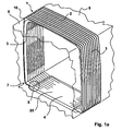
Die Erfindung betrifft einen Balg eines Übergangs zwischen zwei gelenkig miteinander verbundenen Fahrzeugen, wobei der Balg, umfassend Balgboden, Balgdach und Balgseitenwände, eine tunnelartige Röhre bildet, wobei der Balgboden lösbarer Bestandteil des Balges ist, wobei der Balg mehrere in Längsrichtung des Balges hintereinander angeordnete Rahmen aufweist, wobei der Balgboden mehrere hintereinander angeordnete Leisten besitzt.The invention relates to a bellows of a transition between two articulated vehicles, wherein the bellows, comprising bellows bottom, bellows roof and bellows side walls, forms a tunnel-like tube, wherein the bellows bottom is detachable part of the bellows, wherein the bellows a plurality of longitudinally of the bellows behind the other arranged frame has, wherein the bellows bottom has several successively arranged strips.
Aus dem Gebrauchsmuster
Die
Die
Die
Ein Balg der eingangs genannten Art ist beispielsweise aus der
Wie bereits zu eingangs erläutert, besteht der Balg aus Seitenwänden, Boden und Dach. Zur Aufnahme des Bodens durch den Balg weist der Balg im unteren Bereich sogenannte Übergangsbögen auf, das heißt, dass die Balgseitenwände im Bodenbereich durch eine Abwinklung von etwa 90 ° nach innen zu gerichtet sind, wobei der Boden durch den Balg im Bereich der Übergangsbögen lösbar aufnehmbar ist. Der Boden selbst umfasst vorteilhaft lediglich ein Tuch, das aus einem etwa gleichen Material hergestellt ist, wie das Balgdach und die Balgseitenwände, wobei das Tuch auf seiner Unterseite mehrere hintereinander angeordnete Schlaufen aufweist, durch die entsprechende Leisten aufnehmbar sind, wobei eine jede Leiste mit jeweils einem Rahmen verbunden ist.As already explained at the beginning, the bellows consists of side walls, floor and roof. To accommodate the soil through the bellows, the bellows at the bottom of so-called transition bows, that is, that the bellows side walls are directed in the bottom area by an angling of about 90 ° inwards, the bottom by the bellows in the transitional arches releasably receivable is. The bottom itself advantageously comprises only a cloth which is made of a substantially similar material, such as the bellows roof and the bellows side walls, the cloth having on its underside a plurality of successively arranged loops, can be accommodated by the respective strips, each bar with each connected to a frame.
Nach dem Stand der Technik ist zur Verbindung der Leisten und der Rahmen ein sogenanntes Verbindungsprofil vorgesehen, wobei das Verbindungsprofil mehrere Bohrungen aufweist, die mit Bohrungen sowohl in der jeweiligen Leiste als auch in dem jeweiligen Rahmen korrespondieren, und so eine formschlüssige Verbindung zwischen Rahmen und Leiste durch das Verbindungsprofil dadurch geschaffen wird, dass durch die übereinstimmenden Öffnungen beispielsweise Nieten oder Schrauben geschoben werden. Sowohl bei Verwendung von Nieten als auch bei Verwendung von Schrauben geht man von lösbaren Verbindungsmitteln aus.According to the prior art, a so-called connection profile is provided for connecting the strips and the frame, wherein the connection profile has a plurality of holes corresponding to holes in both the respective bar and in the respective frame, and thus a positive connection between the frame and bar is created by the connection profile, that by the matching openings, for example, rivets or screws are pushed. Both when using rivets and when using screws, it is assumed that releasable fasteners.
Des Weiteren ist bekannt, eine jede Leiste mit einem Rahmen dadurch zu verbinden, dass die Leiste mit dem Rahmen ineinanderliegend überlappt und im Bereich der Überlappung ebenfalls zwei durchgehende Bohrungen vorgesehen sind, wobei die durchgehenden Bohrungen ebenfalls der Aufnahme von Schrauben oder Nieten dienen, um eine lösbare Verbindung in gleicher Weise wie zuvor beschrieben herzustellen.Furthermore, it is known to connect each bar with a frame in that the bar overlaps with the frame into each other and in the region of the overlap also two through holes are provided, the through holes also serve to accommodate screws or rivets to a releasable connection in the same manner as described above.
Die Verbindung mit Nieten und Schrauben ist aufwändig, und zwar sowohl in Bezug auf die Montage als auch in Bezug auf die Demontage. Bei der Demontage gilt insbesondere zu berücksichtigen, dass der Nietkopf zum Lösen der Verbindung entweder abgeschert oder abgebohrt werden muss, wohingegen bei einer Verschraubung zu berücksichtigen ist, dass die Schraube erhöhter Verschmutzung unterliegt, weshalb nach einiger Zeit kaum mehr davon auszugehen ist, dass sich eine derartige Schraubverbindung lösen lässt.The connection with rivets and screws is complex, both in terms of assembly and in terms of disassembly. When disassembling is particularly important to take into account that the rivet head to loosen the connection either sheared off or must be drilled, whereas in a screw is to consider that the screw is subject to increased contamination, which is why after a time hardly expect that a can solve such screw.
Eine weitere bekannte Möglichkeit der Verbindung besteht insofern, als im Überlappungsbereich zwischen Rahmen und Leiste durch die dort vorhandenen durchgehenden Öffnungen Bolzen geschoben werden, wobei die Bolzen im Endbereich eine umlaufende nutartige Vertiefung aufweisen, wobei über die Vertiefung ein Federblech geschoben wird, das ein Herausziehen der Kopfbolzen verhindert.Another known possibility of the connection is insofar as in the overlapping area between the frame and strip are pushed through the existing through openings there bolts, the bolts have in the end region of a circumferential groove-like depression, wherein a spring plate is pushed over the recess, which prevents withdrawal of the head bolt.
Das Federblättchen, das über die Enden der Kopfbolzen in die dafür vorgesehene Nut in den Kopfbolzen eingeschoben wird hat den Nachteil, dass sich dieses insbesondere dann, wenn es die Nut nicht richtig erfasst, leicht abziehen lässt. Darüber hinaus hat sich herausgestellt, dass bei Kurvenfahrt, wenn die einzelnen Falten des Balges und mithin die einzelnen Rahmen sich aneinander reiben, dieses Federblättchen trotz korrekter Montage abgeschoben wird, und sich insofern die Verbindung zwischen Leiste und Rahmen löst.The spring blade, which is inserted over the ends of the head bolts in the designated groove in the head bolt has the disadvantage that this can be easily peel off, especially if it does not capture the groove properly. In addition, it has been found that when cornering, when the individual folds of the bellows and thus the individual frames rub against each other, this leaflet is deported despite proper installation, and thus solves the connection between the bar and frame.
Der Erfindung liegt daher die Aufgabe zugrunde, einen Balg eines Übergangs der eingangs genannten Art bereitzustellen, bei dem der Boden in einfacher und preiswerter Weise mit dem Balg verbindbar ist, und wobei darüber hinaus sichergestellt ist, dass die Verbindung jeweils zwischen Rahmen und Leiste dauerhaft aber dennoch leicht lösbar ist.The invention is therefore an object of the invention to provide a bellows of a transition of the type mentioned, in which the soil is connected in a simple and inexpensive way with the bellows, and wherein it is moreover ensured that the connection between each frame and bar permanently but nevertheless easily solvable.
Die Aufgabe wird erfindungsgemäß dadurch gelöst, dass zur Verbindung jeweils eines Rahmens mit einer Leiste eine den Rahmen und die Leiste erfassende Federspange vorgesehen ist, wobei die Federspange mindestens einen Ansatz zum formschlüssigen Verbinden von Rahmen und Leiste aufweist. Hieraus wird deutlich, dass eine solche Spange von unten über die durch sie erfasste Leiste und den Rahmen geschoben wird und durch die Spange Rahmen und Leiste formschlüssig verbunden sind. Die Spange ist vorteilhaft als Federspange ausgebildet, wobei durch die federnde Ausbildung der Spange sichergestellt ist, dass die Spange die formschlüssige Verbindung selbständig aufrecht erhält. Als Mittel zum formschlüssigen Erfassen von Rahmen ist ein Ansatz vorgesehen, der in eine entsprechende Bohrung in Rahmen und Leiste durchdringt, wobei durch die federnde Ausbildung der Spange sichergestellt ist, dass dieser Ansatz in der entsprechenden Bohrung verbleibt und so die formschlüssige Verbindung aufrecht erhält.The object is achieved in that for connecting each of a frame with a bar a frame and the bar detecting spring clip is provided, wherein the spring clip has at least one approach to the positive connection of the frame and bar. From this it is clear that such a clip is pushed from below over the covered by it bar and the frame and the clip frame and bar are positively connected. The clip is advantageously designed as a spring clip, which is ensured by the resilient design of the clip that the clip maintains the positive connection independently. As a means for positive engagement of the frame, an approach is provided which penetrates into a corresponding hole in the frame and bar, which is ensured by the resilient design of the clasp that this Approach remains in the corresponding hole and so maintains the positive connection upright.
Im Einzelnen ist vorgesehen, dass zur Verbindung der jeweiligen Rahmen und Leisten, die jeweils ineinanderliegend einander überlappen, im Bereich der Überlappung sowohl der jeweilige Rahmen als auch die jeweilige Leiste mindestens eine durchgehende Bohrung zur Aufnahme mindestens eines Mittels an der Spange zum formschlüssigen Erfassen von Rahmen und Leiste aufweisen, wobei das Mittel, wie bereits ausgeführt, nach Art eines Ansatzes ausgebildet ist. Das bedeutet, dass im Bereich der übereinanderliegenden Überlappung von Rahmen und Leiste mindestens eine durchgängige Bohrung vorgesehen ist, in die durch die federnde Spange der oder die Ansätze eingedrückt gehalten werden, und so die formschlüssige Verbindung aufrecht erhalten wird. In Bezug auf die Anordnung der Mittel zum formschlüssigen Erfassen von Rahmen und Leiste ist im Einzelnen vorgesehen, dass diese vorteilhaft in etwa U-profilartig gebogene Spange jeweils im Bereich der Schenkel aufeinander zu gerichtet das Mittel zum formschlüssigen Erfassen von Rahmen und Leiste aufweist.Specifically, it is provided that for connecting the respective frame and strips, each overlapping each overlap, in the overlap both the respective frame and the respective bar at least one through hole for receiving at least one means on the clip for form-locking detection of frame and have bar, wherein the means, as already stated, is formed in the manner of a lug. This means that at least one continuous bore is provided in the region of the overlapping overlapping of the frame and strip, in which the spring clip or lugs are kept pressed in, and thus the positive connection is maintained. With regard to the arrangement of the means for positive engagement of the frame and strip is provided in detail that this advantageous in approximately U-profile curved clasp in each case in the region of the legs directed towards each other has the means for positive engagement of the frame and bar.
Sowohl der Rahmen als auch die Leiste sind im Querschnitt U-profilförmig ausgebildet, wobei der Rahmen vorteilhaft die Leiste in dem Rahmen anliegend überlappend aufnimmt. Der oder die Ansätze durchragen hierbei die jeweiligen Schenkel von Rahmen und Leiste.Both the frame and the strip are U-shaped in cross-section, the frame advantageously accommodates the strip in the frame overlapping overlapping. The one or more approaches protrude through the respective legs of the frame and bar.
Als besonders praktisch hat sich herausgestellt, wenn die Spange zu beiden Enden an den Schenkeln aufeinander zu gerichtete Ansätze in Form von Flügeln aufweist, die durch die entsprechenden durchgehenden Bohrungen von Rahmen und Leiste eingreifen und so die formschlüssige Verbindung zwischen Rahmen und Leiste bewirken. Die Flügel können hierbei zu beiden Enden angeordnete Fortsätze an den Schenkeln der Spange sein, die, um in Eingriff mit den entsprechenden Bohrungen gebracht zu werden, rechtwinklig aufeinander zu gebogen, also Bestandteil der Schenkel der Spange sind. Anstelle von Flügeln können vorteilhaft auch Ansätze vorgesehen sein, die bogenförmig ausgebildet sind. Hierzu ist bei der Herstellung der Spange zu jeder Seite des Schenkels der Spange ein T-förmiger Ansatz vorgesehen, der jeweils auf den anderen Schenkel zugerichtet wird, und der Querschenkel des T-förmigen Ansatzes bogenförmig gebogen wird, so dass sich ein kreisbogenförmiger Ansatz ergibt, der jedoch als Kreis nicht gänzlich geschlossen ist.As has been found to be particularly useful when the clip has at both ends on the legs towards each other directed approaches in the form of wings, which engage through the corresponding through holes of the frame and bar, thus causing the positive connection between the frame and bar. The wings may in this case be arranged on both ends projections on the legs of the clip, which, to be brought into engagement with the corresponding holes, bent at right angles to each other, so part the thighs of the clasp are. Instead of wings can advantageously be provided approaches that are arc-shaped. For this purpose, in the manufacture of the clip on each side of the leg of the clip a T-shaped projection is provided, which is trimmed in each case on the other leg, and the transverse leg of the T-shaped projection is bent arcuately, so that there is a circular arc approach, however, as a circle is not completely closed.
Um nun die Spange auf den Rahmen aufsetzen zu können, ist ein zangenförmiges Werkzeug vorgesehen, das die Schenkel der Spange spreizbar erfasst. In diesem Zusammenhang weisen die Schenkel der Spange vorteilhaft zwei einander gegenüberliegende Öffnungen für eine solche Zange, insbesondere eine Seegeringzange auf.In order to be able to place the clasp on the frame, a forceps-shaped tool is provided, which detects the legs of the clasp spreadable. In this context, the legs of the clip advantageously have two opposing openings for such pliers, in particular a Seegeringzange on.
Anhand der Zeichnungen wird die Erfindung nachstehend beispielhaft näher erläutert.
- Fig. 1a
- zeigt hierbei in perspektivischer Darstellung einen Balg mit angedeuteten Fahrzeugteilen zu beiden Seiten des Balges;
- Fig. 1 b
- zeigt den Ausschnitt X aus
Fig. 1 a in stark vergrößerter Darstellung; - Fig. 2a
- zeigt die Federspange in einer ersten Ausführungsform in perspektivischer Darstellung mit seitlich angeordneten Laschen;
- Fig. 2b
- zeigt eine Darstellung einer Federspange gemäß
Fig. 2a , wobei anstelle der seitlich angeordneten Laschen Öffnungen vorgesehen sind; - Fig. 3
- zeigt Rahmen und Leiste in Vorbereitung zur Montage sowie die durch die Seegeringzange gehaltene Federspange;
- Fig. 4
- zeigt in Weiterführung von
Fig. 3 die Federspange mit den flügelartigen Ansätzen kurz vor Eingriff in die dafür vorgesehenen Bohrungen in Rahmen und Leiste; - Fig. 5
- zeigt die fertige Verbindung;
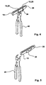
- Fig. 6
- zeigt eine weitere Ausführungsform einer Federspange mit stiftförmigen Ansätzen.
- Fig. 7a-7c
- zeigen eine weitere Ausführungsform einer Spange in drei Ansichten.
- Fig. 1a
- shows a perspective view of a bellows with indicated vehicle parts on both sides of the bellows;
- Fig. 1 b
- shows the section X from
Fig. 1 a in greatly enlarged view; - Fig. 2a
- shows the spring clip in a first embodiment in a perspective view with laterally arranged tabs;
- Fig. 2b
- shows a representation of a spring clip according to
Fig. 2a , wherein openings are provided instead of the laterally arranged tabs; - Fig. 3
- shows frame and strip in preparation for assembly as well as the spring clip held by the Seeger ring pliers;
- Fig. 4
- shows in continuation of
Fig. 3 the spring clip with the wing-like approaches shortly before engagement in the holes provided in the frame and bar; - Fig. 5
- shows the finished connection;
- Fig. 6
- shows a further embodiment of a spring clip with pin-shaped projections.
- Fig. 7a-7c
- show a further embodiment of a clasp in three views.
Bei der Darstellung gemäß
Im Übergang von den Balgseitenwänden 3 zum Balgboden 4 sind sogenannte Übergangsbögen 7 vorgesehen, die sich als nahezu rechtwinklige Abwinklungen der Balgseitenwände in Richtung auf den Balgboden 4 darstellen. Dargestellt ist in
Die Art der Verbindung zwischen dem Rahmen 10 und der Leiste 20 ergibt sich im Einzelnen aus den Darstellungen gemäß den
Die Art der Verbindung des Rahmens 10 mit der Leiste 20 ergibt sich anschaulich aus den
Eine andere Variante einer Federspange ist in
Eine weitere Variante einer Federspange ist in
Claims (8)
- A bellows (1) of a connection between two hinge-linked vehicles (5, 6), said bellows (1), which comprises a bellows bottom (4), a bellows roof (2) and bellows side walls (3), forming a tunnel-like tube, said bellows bottom (4) being a removable constituent part of said bellows (1), said bellows (1) having a plurality of frames (10) disposed one behind the other in the longitudinal direction of said bellows (1), said bellows bottom (4) having a plurality of ledges (20) disposed one behind the other,
characterized in
that, to connect a respective one of a frame (10) with a ledge (20), there is provided a spring cramp (30) taking hold of the frame and the ledge, said spring cramp (30) having at least one shoulder (33) for matingly connecting frame (10) and ledge (20). - The bellows of a connection between two hinge-linked vehicles as set forth in claim 1,
characterized in
that, to connect the frames (10) and the ledges (20), these are lying inside each other and overlap each other, both a respective one of the frames (10) and a respective one of the ledges (20) having in the region of the overlap at least one through hole (15, 25) for receiving the at least one shoulder (33) of the cramp (30) for shape-matingly taking hold of frame (10) and ledge (20). - The bellows of a connection between two hinge-linked vehicles as set forth in claim 2,
characterized in
that the cramp (30) is bent to an approximately U-shaped profile in cross section, that it comprises two legs (32), said legs (32) comprising each the shoulders (33) directed toward each other for shape-matingly taking hold of frame (10) and ledge (20). - The bellows of a connection between two hinge-linked vehicles as set forth in any one of the afore mentioned claims,
characterized in
that the shoulder (33) is configured like a pin. - The bellows of a connection between two hinge-linked vehicles as set forth in any one of the afore mentioned claims,
characterized in
that the shoulder (33) is configured like a wing. - The bellows of a connection between two hinge-linked vehicles as set forth in any one of the afore mentioned claims,
characterized in
that, at either ends of the legs (32), the cramp (30) has shoulders (33) directed toward each other and more specifically configured in the form of wings that engage through corresponding through holes (15, 25) in frame (10) and ledge (20), thus effecting a shape-mating connection between frame (10) and ledge (20). - The bellows of a connection between two hinge-linked vehicles as set forth in any one of the afore mentioned claims,
characterized in
that the legs (32) of the cramp (30) are adapted to be urged apart by a pliers-shaped tool (40). - The bellows of a connection between two hinge-linked vehicles as set forth in any one of the afore mentioned claims,
characterized in
that the legs (32) of the cramp (30) have two confronting openings (36) or clips for circlip ring pliers (40).
Priority Applications (1)
| Application Number | Priority Date | Filing Date | Title |
|---|---|---|---|
| PL06023288T PL1810852T3 (en) | 2006-01-19 | 2006-11-09 | Bellows of a passage between two articulated vehicles |
Applications Claiming Priority (1)
| Application Number | Priority Date | Filing Date | Title |
|---|---|---|---|
| DE102006002655A DE102006002655B4 (en) | 2006-01-19 | 2006-01-19 | Bellows a transition between two articulated vehicles |
Publications (2)
| Publication Number | Publication Date |
|---|---|
| EP1810852A1 EP1810852A1 (en) | 2007-07-25 |
| EP1810852B1 true EP1810852B1 (en) | 2008-03-05 |
Family
ID=37814722
Family Applications (1)
| Application Number | Title | Priority Date | Filing Date |
|---|---|---|---|
| EP06023288A Active EP1810852B1 (en) | 2006-01-19 | 2006-11-09 | Bellows of a passage between two articulated vehicles |
Country Status (8)
| Country | Link |
|---|---|
| US (1) | US7568435B2 (en) |
| EP (1) | EP1810852B1 (en) |
| AT (1) | ATE388032T1 (en) |
| DE (2) | DE102006002655B4 (en) |
| DK (1) | DK1810852T3 (en) |
| ES (1) | ES2301127T3 (en) |
| PL (1) | PL1810852T3 (en) |
| PT (1) | PT1810852E (en) |
Cited By (1)
| Publication number | Priority date | Publication date | Assignee | Title |
|---|---|---|---|---|
| RU2800341C2 (en) * | 2019-05-22 | 2023-07-20 | Ультимейт Юроп Транспортейшн Эквипмент Гмбх | Bellows element |
Families Citing this family (19)
| Publication number | Priority date | Publication date | Assignee | Title |
|---|---|---|---|---|
| DE102006002655B4 (en) * | 2006-01-19 | 2008-03-06 | Hübner GmbH | Bellows a transition between two articulated vehicles |
| DE502007001734D1 (en) * | 2007-06-14 | 2009-11-26 | Huebner Gmbh | Two articulated vehicles coupled together with a transition with at least one bellows and a coupling device comprising two coupling elements |
| ES2348124T3 (en) * | 2008-03-31 | 2010-11-30 | Atg Autotechnik Gmbh | INTERCOM COMMUNICATION FUELLE. |
| IT1390798B1 (en) * | 2008-07-31 | 2011-10-19 | Pei Protezioni Elaborazioni | CONNECTION DEVICE BETWEEN THE BELLOWS AND THE FRAME OF ARTICULATED VEHICLES. |
| IT1390795B1 (en) * | 2008-07-31 | 2011-10-19 | Pei Protezioni Elaborazioni | BELLOW CONNECTION DEVICE FOR ARTICULATED VEHICLES. |
| ES2524066T3 (en) | 2009-03-05 | 2014-12-03 | HÜBNER GmbH & Co. KG | Device for the lateral covering of the separation between two vehicles coupled to each other, in particular vehicles on rails |
| FR2952014B1 (en) * | 2009-10-30 | 2011-12-09 | Lohr Ind | DEFORMABLE ASSEMBLY FOR INTERCULCULATING PASSAGE BETWEEN TWO SUCCESSIVE ROLLING BASE TRAYS |
| PL2604451T3 (en) * | 2011-12-16 | 2014-09-30 | Huebner Gmbh & Co Kg | Gaiter or gangway bellows for the intersection of two vehicles with a jointed connection |
| EP2740618B1 (en) * | 2012-12-05 | 2017-11-22 | Hübner GmbH & Co. KG | Vehicle comprising at least two vehicle parts with a pivoted connection |
| US9278593B1 (en) * | 2013-08-06 | 2016-03-08 | Dynatect Manufacturing, Inc. | Articulating vehicle bellows |
| EP2853462B1 (en) * | 2013-09-26 | 2019-02-27 | Hübner GmbH & Co. KG | Bellows for a transition between two articulated vehicles or vehicle parts or bellows of a canopy of an air passenger boarding bridge or steps |
| PL3075579T3 (en) * | 2015-04-02 | 2020-11-16 | HÜBNER GmbH & Co. KG | Bellows, e.g. the transition between two vehicles with a jointed connection |
| DK3334671T4 (en) | 2015-08-10 | 2023-05-01 | Dematic S R L | Bellows connecting adjacent carriages, especially carriages of a material handling sorting device |
| DE102016001293A1 (en) * | 2016-02-05 | 2017-08-10 | HÜBNER GmbH & Co. KG | Access tunnel system for the covered guidance of persons |
| AT15496U1 (en) * | 2016-02-11 | 2017-10-15 | Hübner Gmbh & Co Kg | Means for securing a connection of two frontally circumferentially coincident bellows elements of a bellows |
| CN106985845B (en) | 2016-12-30 | 2018-12-21 | 比亚迪股份有限公司 | Vestibule diaphragm main body, vestibule diaphragm assembly and train run-through channel |
| DE102017102626A1 (en) * | 2017-02-09 | 2018-08-09 | HÜBNER GmbH & Co. KG | Multilayer sheet comprising at least one carrier fabric, transition element comprising such a multilayer sheet, and vehicle, passenger boarding bridge or staircase with such a transition element |
| ES2899625T3 (en) * | 2019-05-22 | 2022-03-14 | Ultimate Europe Transp Equipment Gmbh | bellows element |
| AU2020381256A1 (en) * | 2019-11-08 | 2022-05-26 | Leonardo S.P.A. | Closure system of the interconnection of transport units connected to each other in a convoy |
Family Cites Families (19)
| Publication number | Priority date | Publication date | Assignee | Title |
|---|---|---|---|---|
| US2004231A (en) * | 1934-05-18 | 1935-06-11 | George G Wasson | Clip |
| DE1257822B (en) | 1964-12-17 | 1968-01-04 | Waggonfabrik Ag | Attachment of the roof, in particular made of synthetic resin, for rail or road vehicles |
| DE3439807A1 (en) * | 1984-10-31 | 1986-04-30 | Hübner Gummi- und Kunststoff GmbH, 3500 Kassel | COVERAGE OF THE TRACK BETWEEN THE BELLOWS AND THE TURNTABLE SHAPED TRANSITION PLATFORM FROM RAIL AND ROAD JOINTS |
| FR2645097B1 (en) * | 1989-03-28 | 1991-06-21 | Caoutchouc Manuf Plastique | DEFORMABLE MEMBRANE FOR INTERCIRCULATION TUNNEL BETWEEN SUCCESSIVE RAILWAY OR ROAD VEHICLES WITH GROWING DEPTH WAVE |
| DE4105449A1 (en) * | 1991-02-21 | 1992-08-27 | Huebner Gummi & Kunststoff | BELLOWS FOR TRANSITIONS FROM ARTICULATED VEHICLES, HOLDING PROFILE FOR THE FASTENING OF SUCH A BELLOWS ON A ARTICULATED VEHICLE AND KIT FROM SUCH A BELLOWS AND SUCH A HOLDING PROFILE AND INSTALLATION |
| DE9113821U1 (en) * | 1991-06-05 | 1992-01-09 | Liao, Chin-Lien, Dahya Shiang, Taichung, Tw | |
| ES2113911T3 (en) * | 1991-11-27 | 1998-05-16 | Huebner Gummi & Kunststoff | BELLOWS FOR ARTICULATED VEHICLES. |
| DE4227126A1 (en) * | 1992-05-07 | 1993-11-11 | Huebner Gummi & Kunststoff | Articulated connection between two articulated vehicles |
| DE4313330C2 (en) * | 1993-03-01 | 1996-06-05 | Rolf Dr Phil Dipl Ing Garnich | Parenthesis |
| DE4341231A1 (en) * | 1993-07-02 | 1995-06-08 | Huebner Gummi & Kunststoff | Bellows for installation as a transition protection between two articulated vehicles |
| DE4338857A1 (en) * | 1993-11-13 | 1995-05-18 | Huebner Gummi & Kunststoff | Bellows as a transitional protection for articulated vehicles |
| DE9413320U1 (en) * | 1994-08-18 | 1994-11-10 | Huebner Gummi & Kunststoff | Bellows |
| US6076470A (en) * | 1996-05-03 | 2000-06-20 | Hubner Gummi-Und Kunststoff Gmbh | Central frame of a connecting corridor bellows subdivided in two halves |
| DE20020061U1 (en) * | 2000-11-25 | 2001-03-01 | Huebner Gmbh | Bellows of a transition between two articulated vehicles |
| DE10238673C1 (en) * | 2002-08-23 | 2003-12-24 | Huebner Gmbh | Fold or wave of a bellows of a transition between two articulated vehicles or vehicle parts, e.g. an articulated bus |
| FR2866616A1 (en) * | 2004-02-25 | 2005-08-26 | Hutchinson | Flexible floor for interconnection bellows between two vehicles, includes elastomer reinforcements of equal lengths set between ends of adjacent metal blades, and made up of at least two blocks spaced apart from floor longitudinal plane |
| GB2413833B (en) * | 2004-05-08 | 2006-03-22 | Ming-Liang Tsai | Locating device for a retractable strut of a tent or a closet |
| DE102005032218A1 (en) * | 2005-07-09 | 2007-01-11 | Hübner GmbH | Device for covering the gap joint (Spurfugenabdeckung) between the turntable and the bellows of a transition between two articulated vehicle parts |
| DE102006002655B4 (en) * | 2006-01-19 | 2008-03-06 | Hübner GmbH | Bellows a transition between two articulated vehicles |
-
2006
- 2006-01-19 DE DE102006002655A patent/DE102006002655B4/en not_active Expired - Fee Related
- 2006-11-09 ES ES06023288T patent/ES2301127T3/en active Active
- 2006-11-09 EP EP06023288A patent/EP1810852B1/en active Active
- 2006-11-09 DK DK06023288T patent/DK1810852T3/en active
- 2006-11-09 DE DE502006000434T patent/DE502006000434D1/en active Active
- 2006-11-09 PT PT06023288T patent/PT1810852E/en unknown
- 2006-11-09 PL PL06023288T patent/PL1810852T3/en unknown
- 2006-11-09 AT AT06023288T patent/ATE388032T1/en active
- 2006-12-21 US US11/643,351 patent/US7568435B2/en active Active
Cited By (1)
| Publication number | Priority date | Publication date | Assignee | Title |
|---|---|---|---|---|
| RU2800341C2 (en) * | 2019-05-22 | 2023-07-20 | Ультимейт Юроп Транспортейшн Эквипмент Гмбх | Bellows element |
Also Published As
| Publication number | Publication date |
|---|---|
| DE102006002655B4 (en) | 2008-03-06 |
| US20070175355A1 (en) | 2007-08-02 |
| DE102006002655A1 (en) | 2007-08-09 |
| DK1810852T3 (en) | 2008-06-30 |
| DE502006000434D1 (en) | 2008-04-17 |
| EP1810852A1 (en) | 2007-07-25 |
| PT1810852E (en) | 2008-03-24 |
| US7568435B2 (en) | 2009-08-04 |
| PL1810852T3 (en) | 2008-09-30 |
| ES2301127T3 (en) | 2008-06-16 |
| ATE388032T1 (en) | 2008-03-15 |
Similar Documents
| Publication | Publication Date | Title |
|---|---|---|
| EP1810852B1 (en) | Bellows of a passage between two articulated vehicles | |
| EP2029946B1 (en) | Mounting system, in particular for solar modules | |
| DE2230555A1 (en) | PROFILE STRIP FOR FASTENING tarpaulin | |
| DE202007003060U1 (en) | connecting element | |
| EP2055888B1 (en) | Door with seal and door seal for same | |
| DE202010000119U1 (en) | Retaining element with sliders for curtain rails | |
| EP2052650A2 (en) | Mount for a curtain or drapery | |
| DE202009002005U1 (en) | Profilnutanschlussverbinder and arrangement with such a connector | |
| DE2107224C3 (en) | Inner curtain glider made of thermoplastic material | |
| DE2644040C2 (en) | Angle connection for components, in particular profile strips, profile supports and the like. | |
| DE102017109774A1 (en) | mounting hooks | |
| EP0343416B1 (en) | Suspension rail for signs, plates or thelike, specially as mounting rail for display-panels | |
| DE3803335C2 (en) | Suspension device for attaching a cable sleeve to the suspension cable of an aerial cable | |
| DE10320638B4 (en) | Curtain holder | |
| DE1475241A1 (en) | Screwless clamp connection, preferably for angled sheet metal tracks, for example of vehicle bodies | |
| DE10111482B4 (en) | Foldable interchangeable frame and articulated connection therefor | |
| DE2320414A1 (en) | COMPONENT FOR CEILING OR WALL CLADDING | |
| DE19903836C2 (en) | Cover for light and / or ventilation shafts and profile bar therefor | |
| AT525957B1 (en) | Mounting arrangement | |
| DE202010005075U1 (en) | insulating glass pane | |
| DE60319315T2 (en) | Locking element for a grid on a drainage channel and tool for removing the same | |
| DE2318383A1 (en) | DOUBLE LEVER PLIERS | |
| DE102005056129B4 (en) | Corner connection arrangement with toothing | |
| EP1250873B1 (en) | Hanger | |
| DE2246064A1 (en) | HANGING DEVICE FOR SUB-CEILING OR DGL |
Legal Events
| Date | Code | Title | Description |
|---|---|---|---|
| PUAI | Public reference made under article 153(3) epc to a published international application that has entered the european phase |
Free format text: ORIGINAL CODE: 0009012 |
|
| AK | Designated contracting states |
Kind code of ref document: A1 Designated state(s): AT BE BG CH CY CZ DE DK EE ES FI FR GB GR HU IE IS IT LI LT LU LV MC NL PL PT RO SE SI SK TR |
|
| AX | Request for extension of the european patent |
Extension state: AL BA HR MK YU |
|
| 17P | Request for examination filed |
Effective date: 20070709 |
|
| 17Q | First examination report despatched |
Effective date: 20070831 |
|
| GRAP | Despatch of communication of intention to grant a patent |
Free format text: ORIGINAL CODE: EPIDOSNIGR1 |
|
| GRAS | Grant fee paid |
Free format text: ORIGINAL CODE: EPIDOSNIGR3 |
|
| GRAA | (expected) grant |
Free format text: ORIGINAL CODE: 0009210 |
|
| AK | Designated contracting states |
Kind code of ref document: B1 Designated state(s): AT BE BG CH CY CZ DE DK EE ES FI FR GB GR HU IE IS IT LI LT LU LV MC NL PL PT RO SE SI SK TR |
|
| REG | Reference to a national code |
Ref country code: GB Ref legal event code: FG4D Free format text: NOT ENGLISH |
|
| REG | Reference to a national code |
Ref country code: PT Ref legal event code: SC4A Free format text: AVAILABILITY OF NATIONAL TRANSLATION Effective date: 20080312 |
|
| GBT | Gb: translation of ep patent filed (gb section 77(6)(a)/1977) |
Effective date: 20080305 |
|
| REG | Reference to a national code |
Ref country code: CH Ref legal event code: EP Ref country code: CH Ref legal event code: NV Representative=s name: R. A. EGLI & CO. PATENTANWAELTE |
|
| AKX | Designation fees paid |
Designated state(s): AT BE BG CH CY CZ DE DK EE ES FI FR GB GR HU IE IS IT LI LT LU LV MC NL PL PT RO SE SI SK TR |
|
| REG | Reference to a national code |
Ref country code: IE Ref legal event code: FG4D Free format text: LANGUAGE OF EP DOCUMENT: GERMAN |
|
| REF | Corresponds to: |
Ref document number: 502006000434 Country of ref document: DE Date of ref document: 20080417 Kind code of ref document: P |
|
| REG | Reference to a national code |
Ref country code: SE Ref legal event code: TRGR |
|
| REG | Reference to a national code |
Ref country code: GR Ref legal event code: EP Ref document number: 20080401106 Country of ref document: GR |
|
| REG | Reference to a national code |
Ref country code: ES Ref legal event code: FG2A Ref document number: 2301127 Country of ref document: ES Kind code of ref document: T3 |
|
| REG | Reference to a national code |
Ref country code: DK Ref legal event code: T3 |
|
| ET | Fr: translation filed | ||
| PG25 | Lapsed in a contracting state [announced via postgrant information from national office to epo] |
Ref country code: LV Free format text: LAPSE BECAUSE OF FAILURE TO SUBMIT A TRANSLATION OF THE DESCRIPTION OR TO PAY THE FEE WITHIN THE PRESCRIBED TIME-LIMIT Effective date: 20080305 Ref country code: SI Free format text: LAPSE BECAUSE OF FAILURE TO SUBMIT A TRANSLATION OF THE DESCRIPTION OR TO PAY THE FEE WITHIN THE PRESCRIBED TIME-LIMIT Effective date: 20080305 |
|
| REG | Reference to a national code |
Ref country code: PL Ref legal event code: T3 |
|
| REG | Reference to a national code |
Ref country code: HU Ref legal event code: AG4A Ref document number: E003526 Country of ref document: HU |
|
| PG25 | Lapsed in a contracting state [announced via postgrant information from national office to epo] |
Ref country code: SK Free format text: LAPSE BECAUSE OF FAILURE TO SUBMIT A TRANSLATION OF THE DESCRIPTION OR TO PAY THE FEE WITHIN THE PRESCRIBED TIME-LIMIT Effective date: 20080305 |
|
| PG25 | Lapsed in a contracting state [announced via postgrant information from national office to epo] |
Ref country code: RO Free format text: LAPSE BECAUSE OF FAILURE TO SUBMIT A TRANSLATION OF THE DESCRIPTION OR TO PAY THE FEE WITHIN THE PRESCRIBED TIME-LIMIT Effective date: 20080305 |
|
| PG25 | Lapsed in a contracting state [announced via postgrant information from national office to epo] |
Ref country code: IS Free format text: LAPSE BECAUSE OF FAILURE TO SUBMIT A TRANSLATION OF THE DESCRIPTION OR TO PAY THE FEE WITHIN THE PRESCRIBED TIME-LIMIT Effective date: 20080705 |
|
| PLBE | No opposition filed within time limit |
Free format text: ORIGINAL CODE: 0009261 |
|
| STAA | Information on the status of an ep patent application or granted ep patent |
Free format text: STATUS: NO OPPOSITION FILED WITHIN TIME LIMIT |
|
| PG25 | Lapsed in a contracting state [announced via postgrant information from national office to epo] |
Ref country code: LT Free format text: LAPSE BECAUSE OF FAILURE TO SUBMIT A TRANSLATION OF THE DESCRIPTION OR TO PAY THE FEE WITHIN THE PRESCRIBED TIME-LIMIT Effective date: 20080305 |
|
| 26N | No opposition filed |
Effective date: 20081208 |
|
| PG25 | Lapsed in a contracting state [announced via postgrant information from national office to epo] |
Ref country code: EE Free format text: LAPSE BECAUSE OF FAILURE TO SUBMIT A TRANSLATION OF THE DESCRIPTION OR TO PAY THE FEE WITHIN THE PRESCRIBED TIME-LIMIT Effective date: 20080305 Ref country code: BG Free format text: LAPSE BECAUSE OF FAILURE TO SUBMIT A TRANSLATION OF THE DESCRIPTION OR TO PAY THE FEE WITHIN THE PRESCRIBED TIME-LIMIT Effective date: 20080605 |
|
| PG25 | Lapsed in a contracting state [announced via postgrant information from national office to epo] |
Ref country code: MC Free format text: LAPSE BECAUSE OF NON-PAYMENT OF DUE FEES Effective date: 20081130 |
|
| PG25 | Lapsed in a contracting state [announced via postgrant information from national office to epo] |
Ref country code: CY Free format text: LAPSE BECAUSE OF FAILURE TO SUBMIT A TRANSLATION OF THE DESCRIPTION OR TO PAY THE FEE WITHIN THE PRESCRIBED TIME-LIMIT Effective date: 20080305 |
|
| PG25 | Lapsed in a contracting state [announced via postgrant information from national office to epo] |
Ref country code: LU Free format text: LAPSE BECAUSE OF NON-PAYMENT OF DUE FEES Effective date: 20081109 |
|
| PGFP | Annual fee paid to national office [announced via postgrant information from national office to epo] |
Ref country code: DK Payment date: 20131120 Year of fee payment: 8 |
|
| PGFP | Annual fee paid to national office [announced via postgrant information from national office to epo] |
Ref country code: IE Payment date: 20131126 Year of fee payment: 8 Ref country code: CZ Payment date: 20131101 Year of fee payment: 8 Ref country code: PT Payment date: 20130509 Year of fee payment: 8 Ref country code: GB Payment date: 20131120 Year of fee payment: 8 |
|
| PGFP | Annual fee paid to national office [announced via postgrant information from national office to epo] |
Ref country code: FI Payment date: 20131113 Year of fee payment: 8 Ref country code: NL Payment date: 20131121 Year of fee payment: 8 Ref country code: GR Payment date: 20131119 Year of fee payment: 8 |
|
| REG | Reference to a national code |
Ref country code: PT Ref legal event code: MM4A Free format text: LAPSE DUE TO NON-PAYMENT OF FEES Effective date: 20150511 |
|
| REG | Reference to a national code |
Ref country code: NL Ref legal event code: V1 Effective date: 20150601 |
|
| REG | Reference to a national code |
Ref country code: DK Ref legal event code: EBP Effective date: 20141130 |
|
| GBPC | Gb: european patent ceased through non-payment of renewal fee |
Effective date: 20141109 |
|
| REG | Reference to a national code |
Ref country code: GR Ref legal event code: ML Ref document number: 20080401106 Country of ref document: GR Effective date: 20150604 |
|
| PG25 | Lapsed in a contracting state [announced via postgrant information from national office to epo] |
Ref country code: CZ Free format text: LAPSE BECAUSE OF NON-PAYMENT OF DUE FEES Effective date: 20141109 Ref country code: PT Free format text: LAPSE BECAUSE OF NON-PAYMENT OF DUE FEES Effective date: 20150511 Ref country code: FI Free format text: LAPSE BECAUSE OF NON-PAYMENT OF DUE FEES Effective date: 20141109 |
|
| REG | Reference to a national code |
Ref country code: IE Ref legal event code: MM4A |
|
| PG25 | Lapsed in a contracting state [announced via postgrant information from national office to epo] |
Ref country code: GR Free format text: LAPSE BECAUSE OF NON-PAYMENT OF DUE FEES Effective date: 20150604 Ref country code: NL Free format text: LAPSE BECAUSE OF NON-PAYMENT OF DUE FEES Effective date: 20150601 |
|
| PG25 | Lapsed in a contracting state [announced via postgrant information from national office to epo] |
Ref country code: IE Free format text: LAPSE BECAUSE OF NON-PAYMENT OF DUE FEES Effective date: 20141109 Ref country code: GB Free format text: LAPSE BECAUSE OF NON-PAYMENT OF DUE FEES Effective date: 20141109 Ref country code: DK Free format text: LAPSE BECAUSE OF NON-PAYMENT OF DUE FEES Effective date: 20141130 |
|
| REG | Reference to a national code |
Ref country code: FR Ref legal event code: PLFP Year of fee payment: 10 |
|
| REG | Reference to a national code |
Ref country code: FR Ref legal event code: PLFP Year of fee payment: 11 |
|
| REG | Reference to a national code |
Ref country code: FR Ref legal event code: PLFP Year of fee payment: 12 |
|
| PGFP | Annual fee paid to national office [announced via postgrant information from national office to epo] |
Ref country code: SE Payment date: 20171120 Year of fee payment: 12 Ref country code: AT Payment date: 20171121 Year of fee payment: 12 Ref country code: CH Payment date: 20171120 Year of fee payment: 12 Ref country code: ES Payment date: 20171220 Year of fee payment: 12 Ref country code: BE Payment date: 20171120 Year of fee payment: 12 |
|
| REG | Reference to a national code |
Ref country code: DE Ref legal event code: R082 Ref document number: 502006000434 Country of ref document: DE Representative=s name: WALTHER HINZ BAYER PARTG MBB PATENTANWAELTE, DE Ref country code: DE Ref legal event code: R081 Ref document number: 502006000434 Country of ref document: DE Owner name: HUEBNER GMBH & CO. KG, DE Free format text: FORMER OWNER: HUEBNER GMBH, 34123 KASSEL, DE Ref country code: DE Ref legal event code: R082 Ref document number: 502006000434 Country of ref document: DE Representative=s name: WALTHER HINZ BAYER PARTGMBB PATENTANWAELTE, DE |
|
| REG | Reference to a national code |
Ref country code: CH Ref legal event code: PL |
|
| REG | Reference to a national code |
Ref country code: SE Ref legal event code: EUG |
|
| REG | Reference to a national code |
Ref country code: AT Ref legal event code: MM01 Ref document number: 388032 Country of ref document: AT Kind code of ref document: T Effective date: 20181109 |
|
| PG25 | Lapsed in a contracting state [announced via postgrant information from national office to epo] |
Ref country code: SE Free format text: LAPSE BECAUSE OF NON-PAYMENT OF DUE FEES Effective date: 20181110 |
|
| REG | Reference to a national code |
Ref country code: BE Ref legal event code: MM Effective date: 20181130 |
|
| PG25 | Lapsed in a contracting state [announced via postgrant information from national office to epo] |
Ref country code: CH Free format text: LAPSE BECAUSE OF NON-PAYMENT OF DUE FEES Effective date: 20181130 Ref country code: LI Free format text: LAPSE BECAUSE OF NON-PAYMENT OF DUE FEES Effective date: 20181130 |
|
| PG25 | Lapsed in a contracting state [announced via postgrant information from national office to epo] |
Ref country code: AT Free format text: LAPSE BECAUSE OF NON-PAYMENT OF DUE FEES Effective date: 20181109 |
|
| PG25 | Lapsed in a contracting state [announced via postgrant information from national office to epo] |
Ref country code: BE Free format text: LAPSE BECAUSE OF NON-PAYMENT OF DUE FEES Effective date: 20181130 |
|
| REG | Reference to a national code |
Ref country code: ES Ref legal event code: FD2A Effective date: 20200102 |
|
| PG25 | Lapsed in a contracting state [announced via postgrant information from national office to epo] |
Ref country code: ES Free format text: LAPSE BECAUSE OF NON-PAYMENT OF DUE FEES Effective date: 20181110 |
|
| REG | Reference to a national code |
Ref country code: HU Ref legal event code: FH1C Free format text: FORMER REPRESENTATIVE(S): WEICHINGER ANDRAS, DANUBIA SZABADALMI ES JOGI IRODA KFT., HU Representative=s name: DANUBIA SZABADALMI ES JOGI IRODA KFT., HU Ref country code: HU Ref legal event code: GB9C Owner name: HUEBNER GMBH & CO. KG, DE Free format text: FORMER OWNER(S): HUEBNER GMBH, DE |
|
| PGFP | Annual fee paid to national office [announced via postgrant information from national office to epo] |
Ref country code: PL Payment date: 20221028 Year of fee payment: 17 |
|
| PGFP | Annual fee paid to national office [announced via postgrant information from national office to epo] |
Ref country code: TR Payment date: 20231030 Year of fee payment: 18 Ref country code: IT Payment date: 20231130 Year of fee payment: 18 Ref country code: HU Payment date: 20231110 Year of fee payment: 18 Ref country code: FR Payment date: 20231122 Year of fee payment: 18 Ref country code: DE Payment date: 20231120 Year of fee payment: 18 |
|
| PGFP | Annual fee paid to national office [announced via postgrant information from national office to epo] |
Ref country code: PL Payment date: 20231027 Year of fee payment: 18 |