EP1809368B1 - Lokalisierung eines implantierten objekts auf basis einer externen antennenladung - Google Patents
Lokalisierung eines implantierten objekts auf basis einer externen antennenladung Download PDFInfo
- Publication number
- EP1809368B1 EP1809368B1 EP05778045A EP05778045A EP1809368B1 EP 1809368 B1 EP1809368 B1 EP 1809368B1 EP 05778045 A EP05778045 A EP 05778045A EP 05778045 A EP05778045 A EP 05778045A EP 1809368 B1 EP1809368 B1 EP 1809368B1
- Authority
- EP
- European Patent Office
- Prior art keywords
- external antenna
- waveform
- antenna
- electrical parameter
- external
- Prior art date
- Legal status (The legal status is an assumption and is not a legal conclusion. Google has not performed a legal analysis and makes no representation as to the accuracy of the status listed.)
- Expired - Lifetime
Links
Images


Classifications
-
- A—HUMAN NECESSITIES
- A61—MEDICAL OR VETERINARY SCIENCE; HYGIENE
- A61B—DIAGNOSIS; SURGERY; IDENTIFICATION
- A61B5/00—Measuring for diagnostic purposes; Identification of persons
- A61B5/06—Devices, other than using radiation, for detecting or locating foreign bodies ; Determining position of diagnostic devices within or on the body of the patient
-
- A—HUMAN NECESSITIES
- A61—MEDICAL OR VETERINARY SCIENCE; HYGIENE
- A61B—DIAGNOSIS; SURGERY; IDENTIFICATION
- A61B34/00—Computer-aided surgery; Manipulators or robots specially adapted for use in surgery
- A61B34/20—Surgical navigation systems; Devices for tracking or guiding surgical instruments, e.g. for frameless stereotaxis
-
- A—HUMAN NECESSITIES
- A61—MEDICAL OR VETERINARY SCIENCE; HYGIENE
- A61B—DIAGNOSIS; SURGERY; IDENTIFICATION
- A61B90/00—Instruments, implements or accessories specially adapted for surgery or diagnosis and not covered by any of the groups A61B1/00 - A61B50/00, e.g. for luxation treatment or for protecting wound edges
- A61B90/36—Image-producing devices or illumination devices not otherwise provided for
-
- G—PHYSICS
- G01—MEASURING; TESTING
- G01V—GEOPHYSICS; GRAVITATIONAL MEASUREMENTS; DETECTING MASSES OR OBJECTS; TAGS
- G01V3/00—Electric or magnetic prospecting or detecting; Measuring magnetic field characteristics of the earth, e.g. declination, deviation
- G01V3/12—Electric or magnetic prospecting or detecting; Measuring magnetic field characteristics of the earth, e.g. declination, deviation operating with electromagnetic waves
-
- A—HUMAN NECESSITIES
- A61—MEDICAL OR VETERINARY SCIENCE; HYGIENE
- A61B—DIAGNOSIS; SURGERY; IDENTIFICATION
- A61B34/00—Computer-aided surgery; Manipulators or robots specially adapted for use in surgery
- A61B34/20—Surgical navigation systems; Devices for tracking or guiding surgical instruments, e.g. for frameless stereotaxis
- A61B2034/2046—Tracking techniques
- A61B2034/2051—Electromagnetic tracking systems
-
- A—HUMAN NECESSITIES
- A61—MEDICAL OR VETERINARY SCIENCE; HYGIENE
- A61N—ELECTROTHERAPY; MAGNETOTHERAPY; RADIATION THERAPY; ULTRASOUND THERAPY
- A61N1/00—Electrotherapy; Circuits therefor
- A61N1/18—Applying electric currents by contact electrodes
- A61N1/32—Applying electric currents by contact electrodes alternating or intermittent currents
- A61N1/36—Applying electric currents by contact electrodes alternating or intermittent currents for stimulation
- A61N1/372—Arrangements in connection with the implantation of stimulators
- A61N1/378—Electrical supply
- A61N1/3787—Electrical supply from an external energy source
Definitions
- the invention relates to techniques for aligning an external object, such as a primary antenna, with an implanted object, such as a secondary antenna.
- Many implantable medical device systems use magnetically coupled antennas for one or both of telemetry communications and inductive recharging of a power source of the implantable medical device.
- the relative positioning of the primary and secondary, i.e., external and internal, antennas is important to the performance of the system. This is especially true for recharging, where the positioning of the primary antenna has a dramatic impact on the efficiency of the recharge procedure and on the associated time that must be spent recharging.
- Localization of an external device relative to an implanted object can also be very important in, for example, implantable drug pump systems, where it may be necessary to locate a subcutaneous refill port.
- Some existing implantable medical device systems incorporate an antenna, or other implanted object, locating feature.
- This feature has variously been implemented using a signal strength approach, e.g., measuring the strength of a telemetry signal sent by an implantable medical device to the external antenna, or by using a metal detection approach, e.g., measuring the loading of the external antenna caused by the proximity of the implant.
- a signal strength approach e.g., measuring the strength of a telemetry signal sent by an implantable medical device to the external antenna
- a metal detection approach e.g., measuring the loading of the external antenna caused by the proximity of the implant.
- the invention is directed to techniques for locating an implanted object using an external antenna.
- the present invention concerns a method as defined in claim 1.
- the implanted object may be, for example, an internal antenna that facilitates recharging of and/or communication with an implantable medical device (IMD), a refill port for a reservoir of an IMD that includes a pump, i.e., an implantable pump, or an IMD itself.
- IMD implantable medical device
- induced currents in the implanted object cause loading at the external antenna.
- Asymmetry in the loading profile of the external antenna when it is driven by different waveforms e.g., waveforms with different amplitudes, frequencies, pulse widths, or shapes, allows the location of the implanted object relative to the external antenna to be determined.
- a system according to the invention is defined in claim 15 and includes an external device coupled to the external antenna.
- the external device may be, for example, an external programming or recharging device for an IMD with which the implanted object is associated.
- the external device begins driving the external antenna with two or more waveforms in succession.
- the external device measures the value of an electrical parameter associated with the antenna, such as a current through the external antenna or a voltage across the antenna, when the antenna is driven with the waveform.
- the external device or another device, determines the location of the implanted object relative to the external antenna based on the measured electrical parameter values for each of the waveforms.
- the measured electrical parameter values differ and, due the asymmetric loading profile of the external antenna, the difference between the measured electrical parameter values varies as a function of the location of the external antenna relative to the implanted object.
- the external device or other device may apply a plurality of equations to the measured values of the electrical parameter, each of the equations defining a position variable as a function of the electrical parameter.
- the position variables defined by the equations may include radial distance, depth, or angle, and values thereof determined based on the measured electrical parameter values may indicate the location of the implanted object relative to the external antenna.
- the external device or other device may provide information to a user indicating the determined location of the implanted object relative to the external antenna.
- the information may include, for example, an arrow that points in the direction of the implanted object relative to the external antenna, superimposed images (such as circles) that will be lined up when the external antenna is aligned with the implanted object, or a text or audio description of the location of the implanted object relative to the external antenna.
- such as information may be provided to a user as instructions, such as instructions to help a user position the external antenna with respect to an internal antenna in embodiments in which the implanted object is an internal antenna.
- the one or more equations that may be used to determine the position of the internal object relative to the external antenna in the manner described above may be determined prior to use of the external device and antenna to locate the implanted object, e.g., prior to implantation of the object, when the location of the device is known.
- the external device may drive the external antenna with the two or more waveforms that will be later used during location of the object, while the external antenna is moved through a three-dimensional region proximate to the object. For each of the driving waveforms, the external device periodically measures value of the electrical parameter when the external antenna is moved through the region.
- the values of r may be recorded as the antenna is moved through the three-dimensional space, or calculated afterwards based on recorded x and y values.
- the external device may solve the equations for each of the position variables as a function of the electrical parameter. For example, the external device may solve the parametric equations f or r and z in terms of the electrical parameter. In this manner, the external device may determine the plurality of equations, each equation relating a respective position variable to the electrical parameter
- one or more other devices perform some or all of the functions associated with determination of the equations.
- a robotic platform driver may move the external antenna through the three-dimensional region, and periodically determine the position of the antenna relative to the known position of the implantable object.
- the platform driver or another computing device may determine the equations based on electrical parameter values received from the external device, and program the external device with the equations.
- a different external device may be used to drive the antenna and measure electrical parameter values during equation determination, and the external device that will later be used to locate the implanted object may be programmed with determined equations and the waveforms.
- another device may perform some of the functions associated with the eventual location of the implanted object.
- a separate computing device may receive measured electrical parameter values from the external device and apply the equations to the measured values to determine the location of the implanted object relative to the antenna.
- the other device may also provide information to a user based on the determined location, in the manner described above.
- the invention may be capable of providing one or more advantages.
- systems that utilize implanted object location techniques according to the invention may be able provide a user with more detailed information regarding the location of the object relative to the external antenna than is provided by systems using conventional implanted object location techniques. Such information may allow the user to more quickly and accurately locate the object than is possible with conventional systems.
- more accurate placement of the external antenna relative to the internal antenna may improve signal strength for telemetry communications or coupling efficiency for recharging an IMD power source. Improved coupling efficiency for recharging may allow shorter recharge cycles. As another example, more accurate location of a refill port of an implantable pump may allow more accurate refilling of the implantable pump, e.g., with fewer needle sticks.
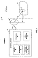
- FIG. 1 is a block diagram illustrating an example system for location of an implanted object.
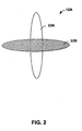
- FIG. 2 is a conceptual diagram illustrating an example external antenna that may be used to locate an implanted object.
- FIG. 3 is a flow diagram illustrating an example technique for locating an implanted object
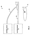
- FIG. 4 is a block diagram illustrating an example system for determining position equations that may be used to determine the location of an implanted object based on measured values of an electrical parameter associated with an external antenna.
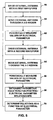
- FIG. 5 is a flow diagram illustrating an example technique for determining position equations that may be used to determine the location of an implanted object based on measured values of an electrical parameter associated with an external antenna.
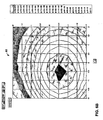
- FIG. 6A and FIG. 6B are exemplary contour maps showing one planar slice of a three-dimensional relationship between position and current for respective drive waveforms.
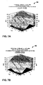
- FIG. 7A and 7B are exemplary diagrams illustrating fitting of current / position relationships with parametric equations.
- FIG. 1 is a block diagram illustrating an example system 10 for location of an implanted object.
- System 10 includes an external antenna 12 used to locate an implanted object 14, and an external device 16 coupled to the external antenna 12 by a cable or other connector 20.
- External antenna 12 may be, for example, a coil antenna.
- implanted object 14 is an internal, e.g., secondary, antenna, which may also be a coil antenna, associated with an implantable medical device (IMD) 18.
- internal antenna 14 may be used with external, e.g., primary, antenna 12 for telemetry communication between external device 16 and IMD 18, or for recharging of a power source of IMD 18.
- identification of the location of internal antenna 14 relative to external antenna 12 may increase the accuracy of placement of external antenna 12, e.g., alignment of antennas 12, 14, which may improve signal strength for telemetry communications, or coupling efficiency during recharging.
- external device 16 may be a recharging device, programming device, or other interrogation device.
- Internal antenna 14 may, as illustrated in FIG. 1 , be located within a housing of IMD 18. However, internal antenna 14 may be located on the outside of the housing of IMD 18, or be a separate structure located some distance away from the housing of IMD 18 and coupled to IMD 18, e.g., via a cable.
- implanted object 14 comprises an internal antenna.
- implanted object 14 may be a fill port associated with an IMD 18 that comprises an implantable reservoir pump.
- accurate location of a refill port may allow more accurate refilling of the reservoir, e.g., with fewer needle sticks.
- an implanted object 14 may be an IMD itself.
- external device 16 need not be a recharging or programming device, but may be any external device, and used whenever location of an implanted object is desired.
- IMD 18 may be an implantable neurostimulator, muscle stimulator, gastric stimulator, pelvic nerve stimulator, bladder stimulator, cardiac pacemaker, pacemaker device with cardioversion and/or defibrillation capabilities, pump, or other implantable device.
- external device 16 exploits asymmetry in the loading profile of external antenna 12 when it is driven by a plurality of different waveforms to determine the location of implanted object 14 relative to external antenna 12.
- antenna 12 When antenna 12 is driven with a waveform, current flows through external antenna 12, thereby generating a magnetic field.
- a conductive object such as the housing of IMD 18 or implanted antenna 14 is placed in close proximity to the coil of external antenna 12, the magnetic field causes currents to flow in the conductive object.
- These currents in turn generate their own magnetic fields that resist the action of the field generated by external antenna 12, which in turn affects electrical parameters associated with the external antenna, e.g., current through or voltage across the external antenna.
- the values of such electrical parameters are related to the amount of conductive material within the vicinity of the magnetic field of external antenna.
- the values of the electrical parameter will differ from waveform to waveform. Due the asymmetric loading profile of external antenna 12, the difference between the measured electrical parameter values also varies as a function of the location of the external antenna relative to the implanted object. The varying difference between the measured electrical parameter values for each of a plurality of different waveforms used to drive antenna 12 may thus be used to determine the location of an implanted object relative to external antenna 12.
- a processor 22 of external device 16 controls measurement at two or more measurement conditions in succession. For example, processor 22 may control generation of a first waveform to drive external antenna 12, and measure a first value of an electrical parameter associated with the antenna, e.g., current through or voltage across the antenna, while the antenna is driven with the first waveform. Processor 22 may then control generation of a second waveform, different from the first, to drive external antenna 12, and measure a second value of the electrical parameter while the antenna is driven with the second waveform.
- processor 22 may control generation of a first waveform to drive external antenna 12, and measure a first value of an electrical parameter associated with the antenna, e.g., current through or voltage across the antenna, while the antenna is driven with the first waveform.
- Processor 22 may then control generation of a second waveform, different from the first, to drive external antenna 12, and measure a second value of the electrical parameter while the antenna is driven with the second waveform.
- external device 16 may include circuitry, such as oscillators and amplifiers, controlled by processor 22 for generation of different waveforms.
- External device 16 may also include circuitry known in the art for measuring electrical parameter values within a circuit, such as resistors and capacitors, which processor 22 may use to determine the electrical parameter values.
- Values i (1) and i (2) are the currents measured when the external antenna was driven with the first and second waveforms respectively, and a,b,c,d,t,u,v and w are coefficients calculated using known depths ( z ) and radial distances ( r ). Applying equations [1] and [2] to current values measured when external antenna 12 was driven with first and second waveforms, processor 22 may determine a radial distance between antennas 12, 14 and a depth of internal antenna 14 relative to external antenna 12.
- the equations may define other position variables in terms of an electrical parameter.
- processor 22 may apply equations that define radial distance and angle, instead of radial distance and depth.
- a memory 26 of external device 16 may store information describing the waveforms 28 with which antenna 12 is to be driven, and the position equations 30.
- processor 22 may provide location information to a user to help the user locate the internal antenna, e.g., align the external and internal antennas, via user interface 24.
- processor 22 may display an arrow that points in the direction the user should move external antenna 12, superimposed images (such as circles) that must be aligned, a text description of where to move external antenna 12, or an audible description, via user interface 24.
- a text description may be output to the user identifying a radial distance from the implantable medical device.
- User interface 24 may include a display, a speaker, a Light Emitting Diode (LED), or the like, and may also include any of a variety of input media, such as buttons, switches, a keypad, a touch screen, or a pointing device.
- LED Light Emitting Diode
- additional drive waveforms may be used to obtain more detailed positioning.
- additional drive waveforms may be used to obtain more detailed positioning.
- addition of a third drive waveform will allow processor 22 to apply equations that define radial distance ( r ) and angle ( ⁇ ), rather than depth, in terms of an electrical parameter.
- the angle ( ⁇ ) may provide greater information regarding the direction in which the internal antenna is located relative to the external antenna than is known when depth ( z ) is determined.
- processor 22 may initiate telemetry communication with IMD 18 via antennas 12, 14 to confirm the presence of IMD 18 and/or internal antenna 14.
- external antenna 12, internal antenna 14 or another implanted object, or IMD 18 may be specifically designed to exaggerate the asymmetric loading of external antenna 12.
- external antenna 12, internal antenna 14, or the housing of the implantable medical device 18 may be an oblong shape instead of a circular shape.
- Processor 22 may include a microprocessor, a controller, a digital signal processor (DSP), an application specific integrated circuit (ASIC), a field-programmable gate array (FPGA), discrete logic circuitry, or the like.
- Memory 26 may include program instructions that, when executed by processor 22, cause processor 22 and external device 15 to perform the functions ascribed to them herein.
- Memory 26 may include any volatile, non-volatile, fixed, removable, magnetic, optical, or electrical media, such as a RAM, ROM, CD-ROM, hard disk, removable magnetic disk, memory cards or sticks, NVRAM, EEPROM, flash memory, and the like.
- FIG. 2 is a conceptual diagram illustrating an example external antenna 12A that may be coupled to an external device 16 for location of an implanted object.
- antenna includes a non-circular shape, which may increase the asymmetry of the loading of external antenna 12 when driven with different waveforms.
- antenna 12A includes two oblong portions 32A and 32B (collectively "portions 32") that are arranged substantially similar to a cross, e.g., are arranged substantially perpendicularly and overlap approximately at their midpoints.
- Portions 32 may be made of different materials with different loading profiles. Further, each of portions 32 may be driven with different waveforms. In this manner, the asymmetry of the loading of external antenna 12 when driven with different waveforms may be further increased.
- FIG. 3 is a flow diagram illustrating an example technique for locating an implanted object.
- external device 16 drives external antenna 12 with a first waveform (34).
- External device 16 measures a first value of an electrical parameter associated with external antenna 12 while the antenna is driven with the first waveform (36).
- External device 16 then drives external antenna 12 with a second waveform (38), and measures a second value of the electrical parameter (40).
- External device 16 determines the location of an implanted object relative to external antenna 12 based on the first and second values of the electrical parameter (42). For example, external device 16 may apply equations that define position variables, such as radial distance ( r ) and depth ( z ) in terms of the electrical parameter, to the measured electrical parameter values, as described above. Based on the determined location, external device 16 provides location information to a physician or other user (44). For example, external device 16 may provide graphical, textual or audible indications of direction, distance, or the like, as described above.
- FIG. 4 is a block diagram illustrating an example system 50 for determining equations that may be used to determine the location of implanted object 14 based on measured values of an electrical parameter associated with external antenna 12, in the manner described above with reference to FIGS. 1 and 3 .
- system 50 includes external antenna 12, antenna 14, external device 16, IMD 18 and cable 20, described above with reference to FIG. 1 .
- system 50 may include a different external antenna, external device and cable.
- the external antenna, external device and cable used during determination of the equations need not be the same external antenna, external device and cable later used during application of the equations to locate the internal antenna.
- the one or more equations used to determine the position of internal antenna 14 relative to external antenna 12 in the manner described above are determined prior to use of external device 16 and antenna 12 to locate antenna 14, when the location of antenna 14 is known.
- the one or more equations may be determined prior to implantation of IMD 18 and antenna 14.
- System 50 includes a platform driver 52, e.g., a robotic platform driver, that is capable of moving a platform 54 in a plurality of directions.
- platform 54 supports antenna 12, and platform driver 52 moves platform 54 such that antenna 12 is moved through a three-dimensional region proximate to IMD 18 and antenna 14. The region may be above the IMD 18 and antenna 14, or may partially or completely surround the antenna.
- platform 54 may support IMD 18 and antenna 14 instead of antenna 12, and platform driver moves platform such that IMD 18 and antenna 14 are moved through a three-dimensional region proximate to antenna.
- platform driver 52 may determine the position the platform relative to an initial position. If antennas 12, 14 are aligned prior to movement of platform 54, the position of platform 54 may reflect the coordinate position ( x,y,z ) of antenna 12 relative to antenna 14. Platform driver 52 may periodically record such information when moving platform through the region proximate to IMD 18 and antenna 14. Platform driver 52 may include circuitry for communication with external device 16, and provide such information to the external device for determination of the equations.
- external device 16 drives the external antenna with the two or more different waveforms
- processor 22 FIG. 1
- Processor 22 periodically measures values of an electrical parameter for each of the waveforms while antenna 12 is driven with the respective waveform.
- processor 22 may determine the position of external antenna 12 relative to internal antenna 14 when each electrical parameter value was measured. Based on the measured electrical parameter values for each waveform, and the associated positions, processor 22 may determine a relationship between the position of external antenna 12 relative to internal antenna 14 and the electrical parameter for each of the waveforms. In other words, processor 22 may determine position / electrical parameter relationships for each waveform. Position / electrical parameter relationships may take the form of matrices.
- Platform driver 52 may record the values of r (radial distance) as antenna 12 is moved through the three-dimensional region, or the driver or external device may calculate radial distances at a later time based on recorded x and y values.
- Processor 22 may solve the parametric equations for each of the position variables as a function of the electrical parameter. For example, processor 22 may solve the parametric equations for r and z in terms of the electrical parameter. In this manner, the processor may determine the plurality of equations, each equation relating a respective position variable to the electrical parameter.
- processor 22 may fit the position / electrical parameter relationships with equations of a higher order.
- external device 16 drives external antenna 12 with additional waveforms, and determines additional position / electrical parameter relationships for each of the waveforms, higher order equations may be applied to the relationships to determine other position variables, such as angle ( ⁇ ), as described above.
- processor 22 may control generation of first and second waveforms to drive external antenna 12 while it is moved first and second times through the region by platform driver 52. For each of the waveforms, processor 22 periodically measures the current through antenna 12 when the antenna is driven by the respective waveform. Processor 22 may measure currents at the same times during each movement of antenna 12 through the region, i.e., when antenna 12 is located at the same positions relative to antenna 14. Based on position information received from platform driver 52 and the measured currents, processor 22 determines position/current relationships for each of the waveforms. Processor 22 determines a parametric equation of best fit for each of the position/current relationships.
- i (1) is current through antenna 12 when driven with the first waveform
- i (2) is current through antenna 12 when driven with the first waveform
- z is the depth
- r is the radial distance
- a,b,c,d,t,u,v and w are coefficients calculated using known depths ( z ) and radial distances ( r ).
- processor 22 solves the parametric position equations for each of the position variables as a function of current measurement.
- the equations may be solved for r and z in terms of current measurements.
- the equations are solved for the variable z as a function of currents i (1) and i (2) .
- processor 22 may determine depth ( z ) in by applying equation [2] to a measured current for each of the two waveforms. With z known, processor 22 may determine radial distance ( r ) by applying equation [1] to one of the measured currents. Equations [1] and [2] may be stored as position equations 30 in memory 26 of external device, as illustrated in FIG.1 , along with the values for a variety of constants. In embodiments, in which an external device different from the one used to determine equations 30 is later used to locate internal antenna, that external device may be programmed with information describing the waveforms 28 to be used and the equations.
- one or more other devices perform some or all of the functions associated with determination of the equations.
- platform driver 52 or another computing device may include a processor that determines the equations based on electrical parameter values received from external device, and programs the external device with the equations.
- another device may perform some of the functions associated with the eventual location of the implanted object.
- a separate computing device may receive measured electrical parameter values from external device 16 and include a processor that applies the equations to the measured values to determine the location of the implanted object relative to the antenna.
- the other device may also include a user interface to provide information to a user based on the determined location, in the manner described above with reference to external device 16.
- FIG. 5 is a flow diagram illustrating an exemplary initialization phase for determining equations that define the position of external antenna 12 relative to an internal object as a function of values of an electrical parameter.
- External device 16 drives external antenna 12 with a first waveform of a particular frequency, shape, pulse width and amplitude (56).
- External antenna 12 is moved through a three-dimensional proximate to the implanted object (58) a first time while the antenna is driven with the first waveform, and values of the electrical parameter are periodically measured while the antenna is driven with the first waveform (60).
- External device 16 drives external antenna 12 with a second waveform has a different frequency, shape, amplitude, pulse width, or a combination thereof(62).
- External antenna 12 is moved through the region a second time while the antenna is driven with the second waveform (64).
- Values of the electrical parameter are periodically measured while external antenna 12 is moved though the region and driven with the second waveform (66).
- External device 16 or the separate computing device next determines position equations for z and r as a function of current measurements as described in detail above (70).
- the position equations may be stored in external device 16 as position equations 30 ( FIG. 1 ).
- the separate computing device may program the position equation into external device 16.
- FIG. 6A illustrates a contour map 80 showing one planar slice of the three-dimensional relationship between position and current for a first drive condition, e.g., using a drive waveform with a frequency of 1115 Hz and an amplitude of 65 mV.
- FIG. 6B illustrates a contour map 82 showing one planar slice of the three-dimensional relationship between position and current for a second drive condition, e.g., using a drive waveform with a frequency of 1095 Hz and an amplitude of 55 mV.
- Contour maps 80, 82 illustrate asymmetric loading of antenna 12 when different waveforms are used to drive the antenna. Further, each of contour maps 80, 82 illustrates bands of constant current in relation to position. From such a relationship, one can get an idea of the distance from the center of the coil of external antenna 12 to the center of the implanted object.
- FIG. 7A and 7B are exemplary diagrams illustrating the fitting of the current and position relationships with parametric equations.
- FIG. 7A illustrates a parametric equation fit 84 for the first measurement condition (i.e., drive waveform with a frequency of 1115 Hz and amplitude of 65 mV) and
- FIG. 7B illustrates a parametric equation fit 86 for the second measurement condition (i.e., drive waveform with a frequency of 1125 Hz and amplitude of 65 mV).
- FIG. 7A and 7B indicate the form of the equation being used and identify the value of the constants calculated using the data points collected.
Landscapes
- Life Sciences & Earth Sciences (AREA)
- Health & Medical Sciences (AREA)
- Engineering & Computer Science (AREA)
- Surgery (AREA)
- Public Health (AREA)
- General Health & Medical Sciences (AREA)
- Veterinary Medicine (AREA)
- Biomedical Technology (AREA)
- Heart & Thoracic Surgery (AREA)
- Medical Informatics (AREA)
- Molecular Biology (AREA)
- Physics & Mathematics (AREA)
- Animal Behavior & Ethology (AREA)
- Remote Sensing (AREA)
- Nuclear Medicine, Radiotherapy & Molecular Imaging (AREA)
- Pathology (AREA)
- Geophysics (AREA)
- Electromagnetism (AREA)
- Environmental & Geological Engineering (AREA)
- Geology (AREA)
- General Life Sciences & Earth Sciences (AREA)
- General Physics & Mathematics (AREA)
- Human Computer Interaction (AREA)
- Biophysics (AREA)
- Robotics (AREA)
- Oral & Maxillofacial Surgery (AREA)
- Radar Systems Or Details Thereof (AREA)
- Position Fixing By Use Of Radio Waves (AREA)
- Measurement Of The Respiration, Hearing Ability, Form, And Blood Characteristics Of Living Organisms (AREA)
- Input Circuits Of Receivers And Coupling Of Receivers And Audio Equipment (AREA)
- Electrotherapy Devices (AREA)
Claims (29)
- Verfahren, das beinhaltet:Erzeugen einer ersten Wellenform in einer externen Vorrichtung (16);Antreiben bzw. Ansteuern einer externen Antenne (12, 12A) mit der ersten Wellenform;Messen eines ersten Wertes eines der externen Antenne zugeordneten elektrischen Parameters, während die externe Antenne mit der ersten Wellenform angesteuert wird;Erzeugen einer zweiten Wellenform in der externen Vorrichtung, wobei die zweite Wellenform wenigstens einen von der ersten Wellenform unterschiedlichen Wellenformparameter aufweist;Ansteuern der externen Antenne mit der zweiten Wellenform;Messen eines zweiten Wertes des elektrischen Parameters, während die externe Antenne mit der zweiten Wellenform angesteuert wird; undBestimmen eines Orts eines implantierten Objekts (14) in Bezug auf die externe Antenne auf Grundlage der ersten und zweiten elektrischen Parameterwerte.
- Verfahren nach Anspruch 1,
bei dem die ersten und zweiten Wellenformen wenigstens unterschiedliche Amplituden, unterschiedliche Frequenzen, unterschiedliche Pulsbreiten und/oder unterschiedliche Formen aufweisen, und
wobei das implantierte Objekt wenigstens eine implantierbare medizinische Vorrichtung, eine einer implantierbaren medizinischen Vorrichtung zugeordnete Antenne und/oder einen einer implantierbaren medizinischen Vorrichtung zugeordneten Befüllungsanschluss aufweist. - Verfahren nach Anspruch 1, das ferner das Bereitstellen einer Anzeige bezüglich des Orts der implantierten medizinischen Vorrichtung in Bezug auf die externe Antenne an einen Benutzer beinhaltet.
- Verfahren nach Anspruch 3, bei dem das Bereitstellen einer Anzeige an den Benutzer das Bereitstellen wenigstens einer Richtung oder einer Distanz beinhaltet.
- Verfahren nach Anspruch 1, bei dem die externe Antenne an einem ersten Ort angeordnet ist, wenn sie mit den ersten und zweiten Wellenformen angesteuert wird, wobei das Verfahren ferner das Bereitstellen von Anweisungen auf Grundlage des bestimmten Ortes des implantierten Objekts an einen Benutzer beinhaltet, die externe Antenne an einen zweiten Ort zu bewegen, der näher bei dem implantierten Objekt liegt als der erste Ort.
- Verfahren nach Anspruch 1,
bei dem das Bestimmen des Ortes des implantierten Objekts in Bezug auf die externe Antenne auf Grundlage der ersten und zweiten elektrischen Parameterwerte das Anwenden erster und zweiter Gleichungen auf die ersten und zweiten elektrischen Parameterwerte beinhaltet, und
bei dem die erste Gleichung eine erste Positionsvariable als eine Funktion des elektrischen Parameters definiert und die zweite Gleichung eine zweite Positionsvariable als eine Funktion des elektrischen Parameters definiert. - Verfahren nach Anspruch 6, bei dem die erste Positionsvariable eine radiale Distanz beinhaltet und die zweite Positionsvariable eine Tiefe beinhaltet.
- Verfahren nach Anspruch 6, das ferner beinhaltet:Erzeugen einer dritten Wellenform in der externen Vorrichtung, wobei die dritte Wellenform wenigstens einen von den ersten und zweiten Wellenformen unterschiedlichen Wellenformparameter aufweist;Ansteuern der externen Antenne mit der dritten Wellenform; undMessen eines dritten Wertes des elektrischen Parameters, während die externe Antenne mit der dritten Wellenform angesteuert wird;wobei das Anwenden der ersten und zweiten Gleichungen auf die ersten und zweiten elektrischen Parameterwerte das Anwenden erster und zweiter Gleichungen auf die ersten, zweiten und dritten elektrischen Parameterwerte beinhaltet, und
wobei die erste Positionsvariable eine radiale Distanz beinhaltet und die zweite Positionsvariable einen Winkel beinhaltet. - Verfahren nach Anspruch 6, das ferner beinhaltet:Bewegen der externen Antenne durch einen dreidimensionalen Bereich in der Nähe des Objekts zu einem ersten Mal;Ansteuern der externen Antenne mit der ersten Wellenform während die externe Antenne zu dem ersten Mal durch den dreidimensionalen Bereich bewegt wird;periodisches Messen von Werten eines der externen Antenne zugeordneten elektrischen Parameters, während die externe Antenne zu dem ersten Mal durch den dreidimensionalen Bereich bewegt und mit der ersten Wellenform angesteuert wird;Bestimmen einer ersten Beziehung zwischen einer Position und einem elektrischen Parameter auf Grundlage der elektrischen Parameterwerte, die gemessen werden, während die externe Antenne mit der ersten Wellenform angesteuert wird, und von Positionen innerhalb des dreidimensionalen Bereichs, in dem die externe Antenne angeordnet war, als die elektrischen Parameterwerte gemessen wurden;Bewegen der externen Antenne durch den dreidimensionalen Bereich zu einem zweiten Mal;Ansteuern der externen Antenne mit der zweiten Wellenform, während die externe Antenne zu dem zweiten Mal durch den dreidimensionalen Bereich bewegt wird;periodisches Messen von Werten des elektrischen Parameters, während die externe Antenne zu dem zweiten Mal durch den dreidimensionalen Bereich bewegt und mit der zweiten Wellenform angesteuert wird;Bestimmen einer zweiten Beziehung zwischen einer Position und einem elektrischen Parameter auf Grundlage der elektrischen Parameterwerte, die gemessen werden, wenn die externe Antenne mit der zweiten Wellenform angesteuert wird, und von Positionen innerhalb des dreidimensionalen Bereichs, in denen die externe Antenne angeordnet war, als die elektrischen Parameterwerte gemessen wurden; undBestimmen der ersten und zweiten Gleichungen auf Grundlage der ersten und zweiten Beziehungen zwischen Positionen und elektrischen Parametern.
- Verfahren nach Anspruch 9, das ferner beinhaltet:Bewegen der externen Antenne durch den dreidimensionalen Bereich zu einem dritten Mal;Ansteuern der externen Antenne mit einer dritten Wellenform, während die externe Antenne zu dem dritten Mal durch den dreidimensionalen Bereich bewegt wird;periodisches Messen von Werten des elektrischen Parameters, während die externe Antenne zu dem dritten Mal durch den dreidimensionalen Bereich bewegt und mit der dritten Wellenform angesteuert wird; undBestimmen einer dritten Beziehung zwischen einer Position und einem elektrischen Parameter auf Grundlage der elektrischen Parameterwerte, die gemessen werden, während die externe Antenne mit der dritten Wellenform angesteuert wird, und von Positionen in dem dreidimensionalen Bereich, in denen die externe Antenne angeordnet war, als die elektrischen Parameterwerte gemessen wurden,wobei das Bestimmen der ersten und zweiten Gleichungen das Bestimmen der ersten und zweiten Gleichungen auf Grundlage der ersten, zweiten und dritten Beziehungen zwischen Position und elektrischen Parametern beinhaltet, und
wobei die erste Positionsvariable eine radiale Distanz beinhaltet und die zweite Positionsvariable einen Winkel beinhaltet. - Verfahren nach Anspruch 9, bei dem das Bestimmen der ersten und zweiten Gleichungen das Anpassen einer Parametergleichung an jede der Beziehungen zwischen Positionen und elektrischen Parametern beinhaltet.
- Verfahren nach Anspruch 9, bei dem das Bewegen der externen Antenne durch einen dreidimensionalen Bereich in der Nähe des Objekts, das Ansteuern der externen Antenne, während die Antenne durch den dreidimensionalen Bereich bewegt wird, und das Messen elektrischer Parameterwerte, während die externe Antenne bewegt und angesteuert wird, das Bewegen der externen Antenne durch einen dreidimensionalen Bereich in der Nähe des Objekts, das Antreiben der externen Antenne, während die Antenne durch den dreidimensionalen Bereich bewegt wird, und das Messen elektrischer Parameterwerte, während die externe Antenne bewegt und angesteuert wird, vor der Implantation des Objekts beinhaltet.
- Verfahren nach Anspruch 1, das ferner das Bestätigen der Anwesenheit des implantierten Objekts unter Verwendung einer Telemetrierückmeldung von einer implantierbaren medizinischen Vorrichtung (18) beinhaltet.
- Verfahren nach Anspruch 1, bei dem das Erzeugen der ersten und zweiten Wellenformen das Erzeugen erster und zweiter vorbestimmter Wellenformen beinhaltet.
- System, das beinhaltet:eine externe Antenne (12, 12A);eine externe Vorrichtung (16), die mit der externen Antenne verbunden ist, wobei die externe Vorrichtung eine erste Wellenform erzeugt, die externe Antenne mit der ersten Wellenform ansteuert, einen ersten Wert eines der externen Antenne zugeordneten elektrischen Parameters misst, während die externe Antenne mit der ersten Wellenform angesteuert wird, eine zweite Wellenform erzeugt, die externe Antenne mit der zweiten Wellenform ansteuert, und einen zweiten Wert des elektrischen Parameters misst, während die externe Antenne mit der zweiten Wellenform angesteuert wird; undeinen Prozessor (22), der einen Ort eines implantierten Objekts in Bezug auf die externe Antenne auf Grundlage der ersten und zweiten elektrischen Parameterwerte bestimmt,wobei die zweite Wellenform wenigstens einen von der ersten Wellenform unterschiedlichen Wellenformparameter aufweist.
- System nach Anspruch 15,
bei dem die ersten und zweiten Wellenformen wenigstens unterschiedliche Amplituden, unterschiedliche Frequenzen, unterschiedliche Pulsbreiten und/oder unterschiedliche Formen aufweisen, und
wobei das implantierte Objekt wenigstens eine implantierbare medizinische Vorrichtung, eine einer implantierbaren medizinischen Vorrichtung zugeordnete Antenne und/oder einen einer implantierbaren medizinischen Vorrichtung zugeordneten Befüllungsanschluss beinhaltet. - System nach Anspruch 15, das ferner ein Benutzerinterface (24) aufweist, wobei der Prozessor eine Anzeige des Orts des implantierten Objekts in Bezug auf die externe Antenne an einen Benutzer über das Benutzerinterface bereitstellt.
- System nach Anspruch 17, bei dem der Prozessor wenigstens eine Richtung oder eine Distanz über das Benutzerinterface bereitstellt.
- System nach Anspruch 15, das ferner ein Benutzerinterface (24) aufweist, wobei die externe Antenne an einem ersten Ort angeordnet ist, wenn sie mit den ersten und zweiten Wellenformen angesteuert wird und der Prozessor Anweisungen an einen Benutzer über das Benutzerinterface auf Grundlage des bestimmten Orts des implantierten Objekts bereitstellt, die externe Antenne an einen zweiten Ort zu bewegen, der näher an dem implantierten Objekt als der erste Ort liegt.
- System nach Anspruch 15, bei dem der Prozessor den Ort des implantierten Objekts in Bezug auf die externe Antenne bestimmt, indem er erste und zweite Gleichungen auf die ersten und zweiten elektrischen Parameterwerte anwendet,
wobei die erste Gleichung eine erste Positionsvariable als eine Funktion des elektrischen Parameters definiert und die zweite Gleichung eine zweite Positionsvariable als eine Funktion des elektrischen Parameters definiert. - System nach Anspruch 20, bei dem die erste Positionsvariable eine radiale Distanz beinhaltet und die zweite Positionsvariable eine Tiefe beinhaltet.
- System nach Anspruch 20,
bei dem die externe Vorrichtung eine dritte Wellenform erzeugt, die externe Antenne mit der dritten Wellenform ansteuert und einen dritten Wert des elektrischen Parameters misst, während sie die externen Antenne mit der dritten Wellenform ansteuert, wobei die dritte Wellenform wenigstens einen von den ersten und zweiten Wellenformen unterschiedlichen Wellenformparameter aufweist,
wobei der Prozessor den Ort des implantierten Objekts in Bezug auf die externe Antenne durch Anwenden der ersten und zweiten Gleichungen auf die ersten, zweiten und dritten elektrischen Parameterwerte bestimmt, und
wobei die erste Positionsvariable eine radiale Distanz beinhaltet und die zweite Positionsvariable einen Winkel beinhaltet. - System nach Anspruch 15, bei dem die externe Vorrichtung die Anwesenheit des implantierten Objekts unter Verwendung einer Telemetrierückmeldung von einer implantierbaren medizinischen Vorrichtung (18) bestätigt.
- System nach Anspruch 15, bei dem der Prozessor einen Prozessor der externen Vorrichtung beinhaltet.
- System nach Anspruch 15, bei dem die externe Vorrichtung eine implantierbare medizinische Vorrichtung, die dem implantierten Objekts zugeordnet ist, wenigstens programmiert, wiederauflädt und/oder wiederbefüllt.
- System nach Anspruch 15, bei dem die externe Antenne dafür eingerichtet ist, einen Unterschied in einer Belastung zu erhöhen, die bei den externen Antennen wahrgenommen wird bzw. auftritt, wenn diese mit den ersten und zweiten Wellenformen angesteuert werden.
- System nach Anspruch 26, bei dem die externe Antenne derart geformt ist, dass sie den Lastunterschied erhöht.
- System nach Anspruch 26,
bei dem die externe Antenne einen ersten Abschnitt (32A), der aus einem ersten Material gebildet ist, und einen zweiten Abschnitt, (32B) der aus einem zweiten Material gebildet ist, beinhaltet, wobei die ersten und zweiten Materialien unterschiedliche Lastprofile aufweisen, und
wobei die externe Vorrichtung den ersten Teil der externen Antenne mit der ersten Wellenform ansteuert und den zweiten Teil der externen Antenne mit der zweiten Wellenform ansteuert. - System nach Anspruch 15, bei dem die ersten und zweiten Wellenformen vorbestimmte Wellenformen darstellen.
Applications Claiming Priority (2)
| Application Number | Priority Date | Filing Date | Title |
|---|---|---|---|
| US58953804P | 2004-07-20 | 2004-07-20 | |
| PCT/US2005/025895 WO2006012426A2 (en) | 2004-07-20 | 2005-07-20 | Locating an implanted object based on external antenna loading |
Publications (2)
| Publication Number | Publication Date |
|---|---|
| EP1809368A2 EP1809368A2 (de) | 2007-07-25 |
| EP1809368B1 true EP1809368B1 (de) | 2010-04-28 |
Family
ID=35457384
Family Applications (1)
| Application Number | Title | Priority Date | Filing Date |
|---|---|---|---|
| EP05778045A Expired - Lifetime EP1809368B1 (de) | 2004-07-20 | 2005-07-20 | Lokalisierung eines implantierten objekts auf basis einer externen antennenladung |
Country Status (5)
| Country | Link |
|---|---|
| US (2) | US7878207B2 (de) |
| EP (1) | EP1809368B1 (de) |
| AT (1) | ATE465774T1 (de) |
| DE (1) | DE602005020965D1 (de) |
| WO (1) | WO2006012426A2 (de) |
Families Citing this family (59)
| Publication number | Priority date | Publication date | Assignee | Title |
|---|---|---|---|---|
| EP1906815A2 (de) * | 2005-07-12 | 2008-04-09 | Alfred E. Mann Institute for Biomedical Engineering at the University of Southern California | Verfahren und gerät zum nachweis von objektorientierung und position |
| US8186358B2 (en) * | 2005-07-29 | 2012-05-29 | Codman Neuro Sciences Sárl | System and method for locating an internal device in a closed system |
| US9610459B2 (en) * | 2009-07-24 | 2017-04-04 | Emkinetics, Inc. | Cooling systems and methods for conductive coils |
| US9339641B2 (en) | 2006-01-17 | 2016-05-17 | Emkinetics, Inc. | Method and apparatus for transdermal stimulation over the palmar and plantar surfaces |
| US20100168501A1 (en) * | 2006-10-02 | 2010-07-01 | Daniel Rogers Burnett | Method and apparatus for magnetic induction therapy |
| US8654868B2 (en) * | 2006-04-18 | 2014-02-18 | Qualcomm Incorporated | Offloaded processing for wireless applications |
| US8289159B2 (en) * | 2006-04-26 | 2012-10-16 | Qualcomm Incorporated | Wireless localization apparatus and method |
| US8406794B2 (en) * | 2006-04-26 | 2013-03-26 | Qualcomm Incorporated | Methods and apparatuses of initiating communication in wireless networks |
| US8600373B2 (en) * | 2006-04-26 | 2013-12-03 | Qualcomm Incorporated | Dynamic distribution of device functionality and resource management |
| WO2007126454A2 (en) * | 2006-04-28 | 2007-11-08 | Medtronic, Inc. | System for transcutaneous energy transfer to an implantable medical device with mating elements |
| CA2665134A1 (en) * | 2006-10-02 | 2008-04-10 | Emkinetics, Inc. | Method and apparatus for magnetic induction therapy |
| US10786669B2 (en) | 2006-10-02 | 2020-09-29 | Emkinetics, Inc. | Method and apparatus for transdermal stimulation over the palmar and plantar surfaces |
| US11224742B2 (en) | 2006-10-02 | 2022-01-18 | Emkinetics, Inc. | Methods and devices for performing electrical stimulation to treat various conditions |
| US9005102B2 (en) | 2006-10-02 | 2015-04-14 | Emkinetics, Inc. | Method and apparatus for electrical stimulation therapy |
| US8626308B2 (en) * | 2008-04-02 | 2014-01-07 | Cochlear Limited | Adjustable transcutaneous energy transfer system |
| US8509909B2 (en) * | 2008-04-10 | 2013-08-13 | Medtronic, Inc. | Using telemetry coupling as a surrogate for recharger coupling |
| US9034910B2 (en) | 2008-06-09 | 2015-05-19 | Allergan, Inc. | Methods of treating alpha adrenergic mediated conditions |
| ITMI20090568A1 (it) * | 2009-04-08 | 2010-10-09 | Luciano Cencioni | Gruppo per il rilevamento della posizione di un dispositivo medicale all'interno di un organismo |
| CA2778963A1 (en) | 2009-10-26 | 2011-05-05 | Emkinetics, Inc. | Method and apparatus for electromagnetic stimulation of nerve, muscle, and body tissues |
| US8764624B2 (en) * | 2010-02-25 | 2014-07-01 | Apollo Endosurgery, Inc. | Inductively powered remotely adjustable gastric banding system |
| US8588884B2 (en) | 2010-05-28 | 2013-11-19 | Emkinetics, Inc. | Microneedle electrode |
| US8937841B2 (en) * | 2012-05-16 | 2015-01-20 | SK Hynix Inc. | Driver for semiconductor memory and method thereof |
| WO2014036449A1 (en) | 2012-08-31 | 2014-03-06 | Alfred E. Mann Foundation For Scientific Research | Feedback controlled coil driver for inductive power transfer |
| US9435830B2 (en) * | 2013-01-18 | 2016-09-06 | Cyberonics, Inc. | Implantable medical device depth estimation |
| JP6298145B2 (ja) | 2013-03-15 | 2018-03-20 | アルフレッド イー. マン ファウンデーション フォー サイエンティフィック リサーチ | 高速のターンオン時間をもつ電流検出複数出力電流刺激装置 |
| AU2014232255B2 (en) | 2013-03-15 | 2017-08-31 | Alfred E. Mann Foundation For Scientific Research | High voltage monitoring successive approximation analog to digital converter |
| JP6702856B2 (ja) | 2013-05-03 | 2020-06-03 | アルフレッド イー. マン ファウンデーション フォー サイエンティフィック リサーチ | 埋め込み型デバイス用高信頼性ワイヤ溶接 |
| JP6513638B2 (ja) | 2013-05-03 | 2019-05-15 | アルフレッド イー. マン ファウンデーション フォー サイエンティフィック リサーチ | 皮下領域刺激のための多枝刺激電極 |
| CN105658276B (zh) | 2013-05-03 | 2018-10-02 | 艾尔弗雷德·E·曼科学研究基金会 | 植入物再充电器握手系统和方法 |
| CN105263572B (zh) * | 2013-07-29 | 2017-10-17 | 艾尔弗雷德·E·曼科学研究基金会 | 用于植入式装置的高效率磁链路 |
| JP6781865B2 (ja) | 2013-07-29 | 2020-11-11 | アルフレッド イー. マン ファウンデーション フォー サイエンティフィック リサーチ | マイクロプロセッサ制御されたeクラスドライバ |
| EP3028365A1 (de) | 2013-07-29 | 2016-06-08 | Alfred E. Mann Foundation for Scientific Research | Implantatladefeldsteuerung durch funkverbindung |
| DE102013108733A1 (de) * | 2013-08-12 | 2015-02-12 | Wittenstein Ag | Vorrichtung und Verfahren zur Ausrichtung einer Primäreinrichtung |
| KR20160145148A (ko) | 2014-04-15 | 2016-12-19 | 하트웨어, 인코포레이티드 | 개선된 경피성 에너지 전달 시스템 |
| KR20160145149A (ko) | 2014-04-15 | 2016-12-19 | 하트웨어, 인코포레이티드 | 개선된 경피성 에너지 전달 시스템 |
| US9700731B2 (en) | 2014-08-15 | 2017-07-11 | Axonics Modulation Technologies, Inc. | Antenna and methods of use for an implantable nerve stimulator |
| AU2015301489B2 (en) | 2014-08-15 | 2020-01-23 | Axonics Modulation Technologies, Inc. | External pulse generator device and associated methods for trial nerve stimulation |
| AU2015301401B2 (en) | 2014-08-15 | 2020-01-16 | Axonics Modulation Technologies, Inc. | Electromyographic lead positioning and stimulation titration in a nerve stimulation system for treatment of overactive bladder |
| CN107073258B (zh) | 2014-08-15 | 2020-02-21 | 艾克索尼克斯调制技术股份有限公司 | 用于基于神经定位来进行神经刺激电极配置的系统和方法 |
| CA2958210C (en) | 2014-08-15 | 2023-09-26 | Axonics Modulation Technologies, Inc. | Integrated electromyographic clinician programmer for use with an implantable neurostimulator |
| AU2015301398B2 (en) | 2014-08-15 | 2020-05-21 | Axonics Modulation Technologies, Inc. | Implantable lead affixation structure for nerve stimulation to alleviate bladder dysfunction and other indications |
| CN107427685B (zh) | 2015-01-09 | 2021-09-21 | 艾克索尼克斯股份有限公司 | 与神经刺激充电设备一起使用的附接设备及相关联方法 |
| WO2016112398A1 (en) | 2015-01-09 | 2016-07-14 | Axonics Modulation Technologies, Inc. | Patient remote and associated methods of use with a nerve stimulation system |
| US9788756B2 (en) | 2015-04-20 | 2017-10-17 | Medtronic, Inc. | Systems, devices, methods, and computer-readable storage facilitating locating an implantable medical device within a body |
| CN107847731B (zh) | 2015-07-10 | 2019-06-28 | 艾克索尼克斯调制技术股份有限公司 | 具有无asic的内部电子设备的可植入神经刺激器以及使用方法 |
| JP6876363B2 (ja) | 2016-01-29 | 2021-05-26 | アクソニクス モジュレーション テクノロジーズ インコーポレイテッド | 埋込可能な神経刺激器の充電を最適化する周波数調製のための方法およびシステム |
| WO2017139784A1 (en) | 2016-02-12 | 2017-08-17 | Axonics Modulation Technologies, Inc. | External pulse generator device and associated methods for trial nerve stimulation |
| BR112018073997B1 (pt) | 2016-05-24 | 2020-01-07 | Synergia Medical | Sistema para centrar um elemento externo com relação a um dispositivo médico implantável e método para alinhamento de um elemento externo com um dispositivo médico implantável implantado sob a pele de um paciente |
| US11110283B2 (en) | 2018-02-22 | 2021-09-07 | Axonics, Inc. | Neurostimulation leads for trial nerve stimulation and methods of use |
| US12427294B2 (en) | 2018-07-13 | 2025-09-30 | C. R. Bard, Inc. | Implantable ports, implantable port-detecting devices, and methods thereof |
| US11664585B2 (en) | 2018-07-23 | 2023-05-30 | Ohio State Innovation Foundation | Bio-matched antenna |
| WO2020185902A1 (en) | 2019-03-11 | 2020-09-17 | Axonics Modulation Technologies, Inc. | Charging device with off-center coil |
| US11439829B2 (en) | 2019-05-24 | 2022-09-13 | Axonics, Inc. | Clinician programmer methods and systems for maintaining target operating temperatures |
| WO2020242900A1 (en) | 2019-05-24 | 2020-12-03 | Axonics Modulation Technologies, Inc. | Trainer device for a neurostimulator programmer and associated methods of use with a neurostimulation system |
| CN116157058B (zh) | 2020-07-21 | 2025-08-12 | 德普伊新特斯产品公司 | 骨固定监测系统 |
| US12420103B1 (en) | 2020-08-20 | 2025-09-23 | Axonics, Inc. | Neurostimulation leads with reduced current leakage |
| DE102021109685B4 (de) | 2021-02-01 | 2026-02-12 | Walter Mehnert | Ladegerät |
| FR3120302B1 (fr) * | 2021-03-08 | 2025-04-04 | Bonetag | procédé d’imagerie d’un implant implanté |
| US12458292B2 (en) | 2021-07-16 | 2025-11-04 | DePuy Synthes Products, Inc. | Smart plate sensors |
Family Cites Families (31)
| Publication number | Priority date | Publication date | Assignee | Title |
|---|---|---|---|---|
| US4255710A (en) * | 1978-05-19 | 1981-03-10 | Weber Harold J | Plural search frequency directional metal detector apparatus having enhanced sensitivity |
| US4223679A (en) * | 1979-02-28 | 1980-09-23 | Pacesetter Systems, Inc. | Telemetry means for tissue stimulator system |
| US4281664A (en) * | 1979-05-14 | 1981-08-04 | Medtronic, Inc. | Implantable telemetry transmission system for analog and digital data |
| US4361153A (en) * | 1980-05-27 | 1982-11-30 | Cordis Corporation | Implant telemetry system |
| US4494545A (en) * | 1980-05-27 | 1985-01-22 | Cordis Corporation | Implant telemetry system |
| US4642786A (en) * | 1984-05-25 | 1987-02-10 | Position Orientation Systems, Ltd. | Method and apparatus for position and orientation measurement using a magnetic field and retransmission |
| US4541431A (en) * | 1984-09-20 | 1985-09-17 | Telectronics Pty. Ltd. | Use of telemetry coil to replace magnetically activated reed switch in implantable devices |
| ZA87810B (en) | 1986-02-04 | 1987-09-30 | Minelab Electronic Ltd | Discriminatory detection of conducting particles |
| NL8701644A (nl) | 1987-07-13 | 1989-02-01 | Cordis Europ | Inrichting voor dosering in het lichaam van een vloeibaar materiaal. |
| US5057095A (en) * | 1989-11-16 | 1991-10-15 | Fabian Carl E | Surgical implement detector utilizing a resonant marker |
| US5117825A (en) * | 1990-11-09 | 1992-06-02 | John Grevious | Closed loop transmitter for medical implant |
| US5314453A (en) * | 1991-12-06 | 1994-05-24 | Spinal Cord Society | Position sensitive power transfer antenna |
| US5324315A (en) * | 1993-08-12 | 1994-06-28 | Medtronic, Inc. | Closed-loop downlink telemetry and method for implantable medical device |
| US5562714A (en) * | 1995-02-03 | 1996-10-08 | Medtronic, Inc. | Magnetic field strength regulator for implant |
| US5702431A (en) * | 1995-06-07 | 1997-12-30 | Sulzer Intermedics Inc. | Enhanced transcutaneous recharging system for battery powered implantable medical device |
| US5690693A (en) | 1995-06-07 | 1997-11-25 | Sulzer Intermedics Inc. | Transcutaneous energy transmission circuit for implantable medical device |
| US5766232A (en) * | 1996-05-10 | 1998-06-16 | Medtronic, Inc. | Method and apparatus for altering the Q of an implantable medical device telemetry antenna |
| US6305381B1 (en) * | 1998-02-02 | 2001-10-23 | Medtronic Inc. | System for locating implantable medical device |
| US6009878A (en) | 1998-02-02 | 2000-01-04 | Medtronic, Inc. | System for locating implantable medical device |
| US6321118B1 (en) * | 1999-01-28 | 2001-11-20 | Advanced Bionics Corporation | Method and apparatus for power link detection with implantable medical devices |
| DE19908438C2 (de) * | 1999-02-26 | 2003-05-15 | Cochlear Ltd | Vorrichtung und Verfahren zum Unterstützen der Positionierung eines externen Sendeteils mit Bezug auf ein implantierbares Empfangsteil eines Ladesystems eines implantierbaren medizinischen Gerätes |
| US6212430B1 (en) * | 1999-05-03 | 2001-04-03 | Abiomed, Inc. | Electromagnetic field source with detection of position of secondary coil in relation to multiple primary coils |
| US6516227B1 (en) * | 1999-07-27 | 2003-02-04 | Advanced Bionics Corporation | Rechargeable spinal cord stimulator system |
| US7177690B2 (en) * | 1999-07-27 | 2007-02-13 | Advanced Bionics Corporation | Implantable system having rechargeable battery indicator |
| US6473652B1 (en) * | 2000-03-22 | 2002-10-29 | Nac Technologies Inc. | Method and apparatus for locating implanted receiver and feedback regulation between subcutaneous and external coils |
| US20010000187A1 (en) * | 2000-10-23 | 2001-04-05 | Case Western Reserve University | Functional neuromuscular stimulation system |
| US20020151770A1 (en) * | 2001-01-04 | 2002-10-17 | Noll Austin F. | Implantable medical device with sensor |
| US6647299B2 (en) * | 2001-09-21 | 2003-11-11 | Medtronic, Inc. | Patient programmer for implantable medical device with audio locator signal |
| US7256695B2 (en) * | 2002-09-23 | 2007-08-14 | Microstrain, Inc. | Remotely powered and remotely interrogated wireless digital sensor telemetry system |
| US7248165B2 (en) * | 2003-09-09 | 2007-07-24 | Motorola, Inc. | Method and apparatus for multiple frequency RFID tag architecture |
| US8140168B2 (en) * | 2003-10-02 | 2012-03-20 | Medtronic, Inc. | External power source for an implantable medical device having an adjustable carrier frequency and system and method related therefore |
-
2005
- 2005-07-20 EP EP05778045A patent/EP1809368B1/de not_active Expired - Lifetime
- 2005-07-20 AT AT05778045T patent/ATE465774T1/de not_active IP Right Cessation
- 2005-07-20 WO PCT/US2005/025895 patent/WO2006012426A2/en not_active Ceased
- 2005-07-20 US US11/186,388 patent/US7878207B2/en not_active Expired - Fee Related
- 2005-07-20 DE DE602005020965T patent/DE602005020965D1/de not_active Expired - Lifetime
-
2010
- 2010-12-22 US US12/976,297 patent/US8015978B2/en not_active Expired - Lifetime
Also Published As
| Publication number | Publication date |
|---|---|
| US7878207B2 (en) | 2011-02-01 |
| EP1809368A2 (de) | 2007-07-25 |
| ATE465774T1 (de) | 2010-05-15 |
| WO2006012426A8 (en) | 2006-05-04 |
| WO2006012426A2 (en) | 2006-02-02 |
| WO2006012426A3 (en) | 2006-03-16 |
| US20060016452A1 (en) | 2006-01-26 |
| US20110118591A1 (en) | 2011-05-19 |
| DE602005020965D1 (de) | 2010-06-10 |
| US8015978B2 (en) | 2011-09-13 |
Similar Documents
| Publication | Publication Date | Title |
|---|---|---|
| EP1809368B1 (de) | Lokalisierung eines implantierten objekts auf basis einer externen antennenladung | |
| EP3497775B1 (de) | Systeme und verfahren zur ortung von implantierten vorrichtungen zur drahtlosen stromübertragung | |
| EP3636149B1 (de) | Systeme, vorrichtungen und verfahren zur positionsbestimmung medizinischer vorrichtungen | |
| EP1052935B1 (de) | Anordnung zur ortung einer implantierbaren medizinischen vorrichtung | |
| US6498477B1 (en) | Mutual crosstalk elimination in medical systems using radiator coils and magnetic fields | |
| US6305381B1 (en) | System for locating implantable medical device | |
| US6473652B1 (en) | Method and apparatus for locating implanted receiver and feedback regulation between subcutaneous and external coils | |
| US12521034B2 (en) | Tracking system and marker device to be tracked by the tracking system for a medical procedure | |
| US6807439B2 (en) | System and method for detecting dislodgement of an implantable medical device | |
| EP3258838B1 (de) | Systeme zur positionsbestimmung medizinischer vorrichtungen | |
| EP1245186A1 (de) | Vorrichtung und Verfahren zur Messung der Menge an intraabdominalem Fett während der Überwachung der Gewichtsabnahme einer Person | |
| US12533505B2 (en) | Neuromodulation apparatus | |
| JPH11503630A (ja) | カテーテルの深さ、位置、及び向きの検出システム | |
| US10543361B2 (en) | System and method for localization of deep brain stimulation electrode via magnetic resonance imaging | |
| EP2640260B1 (de) | System zur ortung medizinischer vorrichtungen | |
| US9424448B2 (en) | Locating device for evaluating the distance between an RFID label and an interface | |
| US20250302329A1 (en) | Implant finder | |
| US20260014887A1 (en) | Method and system for positioning a vehicle having wireless power transfer based on magnetic flux sensing | |
| EP4704716A1 (de) | Ultraschall- und magnetfeld mit magnetoelastischem material zur bestimmung der gewebeeinrastung durch eine medizinische vorrichtung | |
| KR101650284B1 (ko) | 백업기능이 구비된 hifu 시술장치 | |
| EP4032470A1 (de) | System zum empfangen von signalen von einem magneto-mechanischen oszillator | |
| HK40027994B (en) | Medical device position location systems, devices and methods | |
| US20190183379A1 (en) | Medical device location and tracking system | |
| HK40027994A (en) | Medical device position location systems, devices and methods |
Legal Events
| Date | Code | Title | Description |
|---|---|---|---|
| PUAI | Public reference made under article 153(3) epc to a published international application that has entered the european phase |
Free format text: ORIGINAL CODE: 0009012 |
|
| 17P | Request for examination filed |
Effective date: 20070209 |
|
| AK | Designated contracting states |
Kind code of ref document: A2 Designated state(s): AT BE BG CH CY CZ DE DK EE ES FI FR GB GR HU IE IS IT LI LT LU LV MC NL PL PT RO SE SI SK TR |
|
| DAX | Request for extension of the european patent (deleted) | ||
| GRAP | Despatch of communication of intention to grant a patent |
Free format text: ORIGINAL CODE: EPIDOSNIGR1 |
|
| GRAS | Grant fee paid |
Free format text: ORIGINAL CODE: EPIDOSNIGR3 |
|
| GRAA | (expected) grant |
Free format text: ORIGINAL CODE: 0009210 |
|
| AK | Designated contracting states |
Kind code of ref document: B1 Designated state(s): AT BE BG CH CY CZ DE DK EE ES FI FR GB GR HU IE IS IT LI LT LU LV MC NL PL PT RO SE SI SK TR |
|
| REG | Reference to a national code |
Ref country code: GB Ref legal event code: FG4D |
|
| REG | Reference to a national code |
Ref country code: CH Ref legal event code: EP |
|
| REG | Reference to a national code |
Ref country code: IE Ref legal event code: FG4D |
|
| REF | Corresponds to: |
Ref document number: 602005020965 Country of ref document: DE Date of ref document: 20100610 Kind code of ref document: P |
|
| REG | Reference to a national code |
Ref country code: NL Ref legal event code: VDEP Effective date: 20100428 |
|
| LTIE | Lt: invalidation of european patent or patent extension |
Effective date: 20100428 |
|
| PG25 | Lapsed in a contracting state [announced via postgrant information from national office to epo] |
Ref country code: LT Free format text: LAPSE BECAUSE OF FAILURE TO SUBMIT A TRANSLATION OF THE DESCRIPTION OR TO PAY THE FEE WITHIN THE PRESCRIBED TIME-LIMIT Effective date: 20100428 Ref country code: NL Free format text: LAPSE BECAUSE OF FAILURE TO SUBMIT A TRANSLATION OF THE DESCRIPTION OR TO PAY THE FEE WITHIN THE PRESCRIBED TIME-LIMIT Effective date: 20100428 Ref country code: SE Free format text: LAPSE BECAUSE OF FAILURE TO SUBMIT A TRANSLATION OF THE DESCRIPTION OR TO PAY THE FEE WITHIN THE PRESCRIBED TIME-LIMIT Effective date: 20100428 Ref country code: ES Free format text: LAPSE BECAUSE OF FAILURE TO SUBMIT A TRANSLATION OF THE DESCRIPTION OR TO PAY THE FEE WITHIN THE PRESCRIBED TIME-LIMIT Effective date: 20100808 |
|
| PG25 | Lapsed in a contracting state [announced via postgrant information from national office to epo] |
Ref country code: AT Free format text: LAPSE BECAUSE OF FAILURE TO SUBMIT A TRANSLATION OF THE DESCRIPTION OR TO PAY THE FEE WITHIN THE PRESCRIBED TIME-LIMIT Effective date: 20100428 Ref country code: SI Free format text: LAPSE BECAUSE OF FAILURE TO SUBMIT A TRANSLATION OF THE DESCRIPTION OR TO PAY THE FEE WITHIN THE PRESCRIBED TIME-LIMIT Effective date: 20100428 Ref country code: FI Free format text: LAPSE BECAUSE OF FAILURE TO SUBMIT A TRANSLATION OF THE DESCRIPTION OR TO PAY THE FEE WITHIN THE PRESCRIBED TIME-LIMIT Effective date: 20100428 Ref country code: IS Free format text: LAPSE BECAUSE OF FAILURE TO SUBMIT A TRANSLATION OF THE DESCRIPTION OR TO PAY THE FEE WITHIN THE PRESCRIBED TIME-LIMIT Effective date: 20100828 Ref country code: LV Free format text: LAPSE BECAUSE OF FAILURE TO SUBMIT A TRANSLATION OF THE DESCRIPTION OR TO PAY THE FEE WITHIN THE PRESCRIBED TIME-LIMIT Effective date: 20100428 |
|
| PG25 | Lapsed in a contracting state [announced via postgrant information from national office to epo] |
Ref country code: CY Free format text: LAPSE BECAUSE OF FAILURE TO SUBMIT A TRANSLATION OF THE DESCRIPTION OR TO PAY THE FEE WITHIN THE PRESCRIBED TIME-LIMIT Effective date: 20100512 Ref country code: PL Free format text: LAPSE BECAUSE OF FAILURE TO SUBMIT A TRANSLATION OF THE DESCRIPTION OR TO PAY THE FEE WITHIN THE PRESCRIBED TIME-LIMIT Effective date: 20100428 Ref country code: GR Free format text: LAPSE BECAUSE OF FAILURE TO SUBMIT A TRANSLATION OF THE DESCRIPTION OR TO PAY THE FEE WITHIN THE PRESCRIBED TIME-LIMIT Effective date: 20100729 |
|
| PG25 | Lapsed in a contracting state [announced via postgrant information from national office to epo] |
Ref country code: DK Free format text: LAPSE BECAUSE OF FAILURE TO SUBMIT A TRANSLATION OF THE DESCRIPTION OR TO PAY THE FEE WITHIN THE PRESCRIBED TIME-LIMIT Effective date: 20100428 Ref country code: EE Free format text: LAPSE BECAUSE OF FAILURE TO SUBMIT A TRANSLATION OF THE DESCRIPTION OR TO PAY THE FEE WITHIN THE PRESCRIBED TIME-LIMIT Effective date: 20100428 |
|
| PG25 | Lapsed in a contracting state [announced via postgrant information from national office to epo] |
Ref country code: RO Free format text: LAPSE BECAUSE OF FAILURE TO SUBMIT A TRANSLATION OF THE DESCRIPTION OR TO PAY THE FEE WITHIN THE PRESCRIBED TIME-LIMIT Effective date: 20100428 Ref country code: CZ Free format text: LAPSE BECAUSE OF FAILURE TO SUBMIT A TRANSLATION OF THE DESCRIPTION OR TO PAY THE FEE WITHIN THE PRESCRIBED TIME-LIMIT Effective date: 20100428 Ref country code: MC Free format text: LAPSE BECAUSE OF NON-PAYMENT OF DUE FEES Effective date: 20100731 Ref country code: BE Free format text: LAPSE BECAUSE OF FAILURE TO SUBMIT A TRANSLATION OF THE DESCRIPTION OR TO PAY THE FEE WITHIN THE PRESCRIBED TIME-LIMIT Effective date: 20100428 Ref country code: SK Free format text: LAPSE BECAUSE OF FAILURE TO SUBMIT A TRANSLATION OF THE DESCRIPTION OR TO PAY THE FEE WITHIN THE PRESCRIBED TIME-LIMIT Effective date: 20100428 |
|
| REG | Reference to a national code |
Ref country code: CH Ref legal event code: PL |
|
| PLBE | No opposition filed within time limit |
Free format text: ORIGINAL CODE: 0009261 |
|
| STAA | Information on the status of an ep patent application or granted ep patent |
Free format text: STATUS: NO OPPOSITION FILED WITHIN TIME LIMIT |
|
| GBPC | Gb: european patent ceased through non-payment of renewal fee |
Effective date: 20100728 |
|
| PG25 | Lapsed in a contracting state [announced via postgrant information from national office to epo] |
Ref country code: IT Free format text: LAPSE BECAUSE OF FAILURE TO SUBMIT A TRANSLATION OF THE DESCRIPTION OR TO PAY THE FEE WITHIN THE PRESCRIBED TIME-LIMIT Effective date: 20100428 |
|
| 26N | No opposition filed |
Effective date: 20110131 |
|
| PG25 | Lapsed in a contracting state [announced via postgrant information from national office to epo] |
Ref country code: LI Free format text: LAPSE BECAUSE OF NON-PAYMENT OF DUE FEES Effective date: 20100731 Ref country code: CH Free format text: LAPSE BECAUSE OF NON-PAYMENT OF DUE FEES Effective date: 20100731 |
|
| PG25 | Lapsed in a contracting state [announced via postgrant information from national office to epo] |
Ref country code: GB Free format text: LAPSE BECAUSE OF NON-PAYMENT OF DUE FEES Effective date: 20100728 Ref country code: IE Free format text: LAPSE BECAUSE OF NON-PAYMENT OF DUE FEES Effective date: 20100720 |
|
| PGFP | Annual fee paid to national office [announced via postgrant information from national office to epo] |
Ref country code: FR Payment date: 20110727 Year of fee payment: 7 |
|
| PGFP | Annual fee paid to national office [announced via postgrant information from national office to epo] |
Ref country code: DE Payment date: 20110729 Year of fee payment: 7 |
|
| PG25 | Lapsed in a contracting state [announced via postgrant information from national office to epo] |
Ref country code: HU Free format text: LAPSE BECAUSE OF FAILURE TO SUBMIT A TRANSLATION OF THE DESCRIPTION OR TO PAY THE FEE WITHIN THE PRESCRIBED TIME-LIMIT Effective date: 20101029 Ref country code: LU Free format text: LAPSE BECAUSE OF NON-PAYMENT OF DUE FEES Effective date: 20100720 Ref country code: BG Free format text: LAPSE BECAUSE OF FAILURE TO SUBMIT A TRANSLATION OF THE DESCRIPTION OR TO PAY THE FEE WITHIN THE PRESCRIBED TIME-LIMIT Effective date: 20100428 Ref country code: PT Free format text: LAPSE BECAUSE OF FAILURE TO SUBMIT A TRANSLATION OF THE DESCRIPTION OR TO PAY THE FEE WITHIN THE PRESCRIBED TIME-LIMIT Effective date: 20100928 |
|
| PG25 | Lapsed in a contracting state [announced via postgrant information from national office to epo] |
Ref country code: TR Free format text: LAPSE BECAUSE OF FAILURE TO SUBMIT A TRANSLATION OF THE DESCRIPTION OR TO PAY THE FEE WITHIN THE PRESCRIBED TIME-LIMIT Effective date: 20100428 |
|
| REG | Reference to a national code |
Ref country code: FR Ref legal event code: ST Effective date: 20130329 |
|
| PG25 | Lapsed in a contracting state [announced via postgrant information from national office to epo] |
Ref country code: DE Free format text: LAPSE BECAUSE OF NON-PAYMENT OF DUE FEES Effective date: 20130201 Ref country code: FR Free format text: LAPSE BECAUSE OF NON-PAYMENT OF DUE FEES Effective date: 20120731 |
|
| REG | Reference to a national code |
Ref country code: DE Ref legal event code: R119 Ref document number: 602005020965 Country of ref document: DE Effective date: 20130201 |
|
| PG25 | Lapsed in a contracting state [announced via postgrant information from national office to epo] |
Ref country code: BG Free format text: LAPSE BECAUSE OF FAILURE TO SUBMIT A TRANSLATION OF THE DESCRIPTION OR TO PAY THE FEE WITHIN THE PRESCRIBED TIME-LIMIT Effective date: 20100728 |