EP1809012A1 - Image forming apparatus having optical scanning unit and method of adjusting lens position in optical scanning unit - Google Patents
Image forming apparatus having optical scanning unit and method of adjusting lens position in optical scanning unit Download PDFInfo
- Publication number
- EP1809012A1 EP1809012A1 EP07000495A EP07000495A EP1809012A1 EP 1809012 A1 EP1809012 A1 EP 1809012A1 EP 07000495 A EP07000495 A EP 07000495A EP 07000495 A EP07000495 A EP 07000495A EP 1809012 A1 EP1809012 A1 EP 1809012A1
- Authority
- EP
- European Patent Office
- Prior art keywords
- lens
- face
- lens holder
- support member
- optical scanning
- Prior art date
- Legal status (The legal status is an assumption and is not a legal conclusion. Google has not performed a legal analysis and makes no representation as to the accuracy of the status listed.)
- Granted
Links
- 230000003287 optical effect Effects 0.000 title claims abstract description 157
- 238000000034 method Methods 0.000 title claims description 31
- 238000012423 maintenance Methods 0.000 claims description 42
- 238000012546 transfer Methods 0.000 claims description 41
- 239000012260 resinous material Substances 0.000 claims description 13
- 229930182556 Polyacetal Natural products 0.000 claims description 6
- 229920006324 polyoxymethylene Polymers 0.000 claims description 6
- 239000011347 resin Substances 0.000 claims description 6
- 229920005989 resin Polymers 0.000 claims description 6
- 230000003068 static effect Effects 0.000 claims description 5
- 239000011810 insulating material Substances 0.000 claims description 3
- 230000001678 irradiating effect Effects 0.000 claims description 3
- 239000011521 glass Substances 0.000 description 13
- 238000001514 detection method Methods 0.000 description 10
- 230000000694 effects Effects 0.000 description 9
- 230000033001 locomotion Effects 0.000 description 9
- 238000004140 cleaning Methods 0.000 description 6
- 238000003825 pressing Methods 0.000 description 5
- 230000005540 biological transmission Effects 0.000 description 3
- 239000000428 dust Substances 0.000 description 3
- 230000035939 shock Effects 0.000 description 3
- 230000005484 gravity Effects 0.000 description 2
- 238000004519 manufacturing process Methods 0.000 description 2
- 239000002245 particle Substances 0.000 description 2
- 238000005299 abrasion Methods 0.000 description 1
- 229910052782 aluminium Inorganic materials 0.000 description 1
- XAGFODPZIPBFFR-UHFFFAOYSA-N aluminium Chemical compound [Al] XAGFODPZIPBFFR-UHFFFAOYSA-N 0.000 description 1
- 230000000903 blocking effect Effects 0.000 description 1
- 230000015556 catabolic process Effects 0.000 description 1
- 239000003086 colorant Substances 0.000 description 1
- 239000004020 conductor Substances 0.000 description 1
- 238000006731 degradation reaction Methods 0.000 description 1
- 230000001419 dependent effect Effects 0.000 description 1
- 238000013461 design Methods 0.000 description 1
- 230000002708 enhancing effect Effects 0.000 description 1
- 230000002349 favourable effect Effects 0.000 description 1
- 229910052751 metal Inorganic materials 0.000 description 1
- 239000002184 metal Substances 0.000 description 1
- 238000012986 modification Methods 0.000 description 1
- 230000004048 modification Effects 0.000 description 1
- 229920000515 polycarbonate Polymers 0.000 description 1
- 239000004417 polycarbonate Substances 0.000 description 1
- 230000001105 regulatory effect Effects 0.000 description 1
- 238000007790 scraping Methods 0.000 description 1
Images






Classifications
-
- H—ELECTRICITY
- H04—ELECTRIC COMMUNICATION TECHNIQUE
- H04N—PICTORIAL COMMUNICATION, e.g. TELEVISION
- H04N1/00—Scanning, transmission or reproduction of documents or the like, e.g. facsimile transmission; Details thereof
- H04N1/04—Scanning arrangements, i.e. arrangements for the displacement of active reading or reproducing elements relative to the original or reproducing medium, or vice versa
- H04N1/113—Scanning arrangements, i.e. arrangements for the displacement of active reading or reproducing elements relative to the original or reproducing medium, or vice versa using oscillating or rotating mirrors
- H04N1/1135—Scanning arrangements, i.e. arrangements for the displacement of active reading or reproducing elements relative to the original or reproducing medium, or vice versa using oscillating or rotating mirrors for the main-scan only
-
- H—ELECTRICITY
- H04—ELECTRIC COMMUNICATION TECHNIQUE
- H04N—PICTORIAL COMMUNICATION, e.g. TELEVISION
- H04N1/00—Scanning, transmission or reproduction of documents or the like, e.g. facsimile transmission; Details thereof
- H04N1/024—Details of scanning heads ; Means for illuminating the original
- H04N1/032—Details of scanning heads ; Means for illuminating the original for picture information reproduction
-
- H—ELECTRICITY
- H04—ELECTRIC COMMUNICATION TECHNIQUE
- H04N—PICTORIAL COMMUNICATION, e.g. TELEVISION
- H04N2201/00—Indexing scheme relating to scanning, transmission or reproduction of documents or the like, and to details thereof
- H04N2201/024—Indexing scheme relating to scanning, transmission or reproduction of documents or the like, and to details thereof deleted
- H04N2201/02406—Arrangements for positioning elements within a head
- H04N2201/02408—Translational positioning
- H04N2201/02414—Translational positioning in a direction perpendicular to the plane of the photodetector elements, e.g. in the direction of the optical axis
-
- H—ELECTRICITY
- H04—ELECTRIC COMMUNICATION TECHNIQUE
- H04N—PICTORIAL COMMUNICATION, e.g. TELEVISION
- H04N2201/00—Indexing scheme relating to scanning, transmission or reproduction of documents or the like, and to details thereof
- H04N2201/024—Indexing scheme relating to scanning, transmission or reproduction of documents or the like, and to details thereof deleted
- H04N2201/02406—Arrangements for positioning elements within a head
- H04N2201/02416—Rotational positioning, i.e. with respect to an axis
-
- H—ELECTRICITY
- H04—ELECTRIC COMMUNICATION TECHNIQUE
- H04N—PICTORIAL COMMUNICATION, e.g. TELEVISION
- H04N2201/00—Indexing scheme relating to scanning, transmission or reproduction of documents or the like, and to details thereof
- H04N2201/024—Indexing scheme relating to scanning, transmission or reproduction of documents or the like, and to details thereof deleted
- H04N2201/02406—Arrangements for positioning elements within a head
- H04N2201/02427—Element positioned
- H04N2201/02431—Lens or optical system
Definitions
- the present disclosure generally relates to an image forming apparatus, and more particularly to an image forming apparatus having an optical scanning unit and a method of adjusting a lens position in the optical scanning unit.
- a related art image forming apparatus may include an optical writing unit having a moving unit for moving a cylindrical lens to adjust a light-axis direction of cylindrical lens.
- the cylindrical lens may be moved by a driver (e.g. motor) to adjust a light-axis direction of the cylindrical lens.
- a driver e.g. motor
- such related art may need a driver, driving-force transmission mechanism, and a driving mechanism controller, for example, by which such related art may have a complex configuration and need a space for allocating such devices.
- Such a configuration may not be favorable from a viewpoint of miniaturization of image forming apparatus.
- the lens holder may be moved in the light-axis direction by a force applied from a hand of maintenance person to adjust a position of the lens holder.
- a maintenance person may adjust a position of the cylindrical lens in its light-axis direction with a hand force.
- an optical writing unit when adjusting a position of the cylindrical lens in its light-axis direction, an optical writing unit may be placed on a platform of an adjustment machine, wherein a posture or orientation of the optical writing unit on the platform may be set substantially similar to a posture or orientation of the optical writing unit in an image forming apparatus.
- lens-position-adjustment information may be displayed on a display unit as lens-position-adjustment information.
- a maintenance person may check or look up such information to adjust a position of the cylindrical lens.
- the hand of maintenance person may block a path of incident light or outgoing light of the cylindrical lens.
- Such process may not be convenient for the maintenance person because the maintenance person may have to stop a movement of the lens holder to check or look up the lens-position-adjustment information and then restart a movement of the lens holder.
- first, second, etc. may be used herein to describe various elements, components, regions, layers and/or sections, it should be understood that these elements, components, regions, layers and/or sections should not be limited by these terms. These terms are used only to distinguish one element, component, region, layer or section from another region, layer or section. Thus, a first element, component, region, layer or section discussed below could be termed a second element, component, region, layer or section without departing from the teachings of the present invention.
- the cleaning units 13Y, 13C, 13M, and 13K may remove toners remaining on the photoconductors 10Y, 10C, 10M, and 10K, respectively.
- the optical writing unit 4 provided under the image forming units 3Y, 3C, 3M, and 3K, may emit a light beam L to the surface of the photoconductors 10Y, 10C, 10M, and 10K.
- the optical writing unit 4 may be used as optical scanning unit.
- the intermediate transfer unit 5 may further include a belt-cleaning unit 26, which may remove toners remaining on the intermediate transfer belt 20 after the toner images are transferred from the intermediate transfer belt 20 to the transfer sheet P.
- a belt-cleaning unit 26 which may remove toners remaining on the intermediate transfer belt 20 after the toner images are transferred from the intermediate transfer belt 20 to the transfer sheet P.
- the optical writing unit 4 may scan the surfaces of the photoconductors 10Y, 10C, 10M, and 10K with the laser beam L, based on original image information, to form latent images on the surfaces of the photoconductors 10Y, 10C, 10M, and 10K.
- the latent images formed on the surfaces of the photoconductors 10Y, 10C, 10M, and 10K may be developed as toner image by supplying toners from developing rollers 15Y, 15C, 15M, and 15K in the developing units 12Y, 12C, 12M, and 12K to the surface of the photoconductors 10Y, 10C, 10M, and 10K, respectively.
- Each of the light source units 70K, 70M, 70C, 70Y may include a light source, which can emit writing beams Ly, Lc, Lm, and Lk. Each of the writing beams Ly, Lc, Lm, and Lk may scan the photoconductors 10K, 10M, 10C, and 10Y, respectively.
- Each of the polygon mirrors 41a and 41b may have a plurality of side faces used as reflecting mirror, and may be rotated at a higher speed by a polygon motor (not shown) such as 32,000 rpm (revolution per minute), for example.
- the optical writing unit 4 may further include f-theta lens 43a, 43b, first mirrors 44a, 44b, 44c, 44d, second mirrors 46a, 46b, 46c, 46d, third mirrors 47a, 47b, 47c, 47d, and long-shaped lens 50a, 50b, 50c, 50d as shown in FIG. 3.
- the optical writing unit 4 may further include dust-proof glasses 48a, 48b, 48c, and 48d.
- the dust-proof glasses 48a, 48b, 48C, and 48d may reduce or suppress an intrusion of dust such as toner particles into a housing of the optical writing unit 4.
- the optical writing unit 4 may include a housing 100 for containing the above-mentioned parts.
- the lower side of the support plate 100a may be attached with the long-shaped lens 50a for Y color and long-shaped lens 50d for K color.
- the optical writing unit 4 may have the light source units 70Y, 70C, 70M, and 70K, which emit the respective writing beams Ly, Lc, Lm, and Lk based on a signal generated from an original image data.
- Such original image data may be input to the image forming apparatus 1 from a scanner (not shown), personal computer or the like, for example.
- the writing beams (or scanning light beams) Ly, Lc, Lm, and Lk may pass through the f-theta lenses 43a and 43b.
- the light detectors 201Y, 201C, 201M, and 201K may be disposed instead of the photoconductors 10Y, 10C, 10M, and 10K in a configuration shown in FIG. 6, respectively, which may be understood by comparing configurations shown in FIGs. 3 and 6.
- control unit 202 may receive detection signals (e.g., corresponding to light-intensity and beam-spot diameter detected by the light detectors 201Y, 201C, 201M, and 201K) from the light detectors 201Y, 201C, 201M, and 201K, and may display information, corresponding to detection signals, on the display unit 203 as lens-position-adjustment information with a substantially real time manner.
- detection signals e.g., corresponding to light-intensity and beam-spot diameter detected by the light detectors 201Y, 201C, 201M, and 201K
- a maintenance person can conduct an adjustment work for adjusting a position of cylindrical lens 61 to an appropriate position while checking or looking up the lens-position-adjustment information displayed on the display unit 203.
- FIG. 7 is a schematic perspective view of upper side of the optical scanning unit 4 placed on the platform 200 of the adjustment machine, in which a plurality of parts related to a light path such as light source unit 70 and polygon mirrors 41a and 41b are shown.
- the lens adjuster 63 may include an adjusting member 63a, which is provided on an upper side of the support plate 100a, wherein a maintenance person may operate the adjusting member 63a with a driver 160.
- the maintenance person may rotate the adjusting member 63a with the driver 160 while checking or looking-up the lens-position-adjustment information displayed on the display unit 203 to find an appropriate positioning of the cylindrical lens 61 in its light-axis direction.
- the polygon mirrors 41a and 41b may deflect a scanning light beam. Then, such scanning light beam may reflect at the first mirrors 44a, 44b, 44c, 44d, the second mirrors 46a, 46b, 46c, 46d, and the third mirrors 47a, 47b, 47c, 47d.
- the driver 160 may block a part of the scanning light beam when conducting an adjustment work of the cylindrical lens 61.
- FIG. 9 is a schematic cross sectional view of the optical scanning unit 4, in which a positioning of the lens unit 60 is shown.
- the lower side of the support plate 100a may include two lens-receiving faces 100b, formed in a parallel direction of the light-axis direction of the cylindrical lens 61, for example.
- the cylindrical lens 61 may need to be precisely positioned when the cylindrical lens 61 is moved in its light-axis direction D to maintain alignment of the lens focal line of cylindrical lens 61 and scanning face of polygon mirrors 41a and 41b at a preferable manner.
- an intervening part may be disposed between the cylindrical lens 61 and the lens-receiving face 100b, wherein the lens-receiving face 100b may be used for determining the positioning of the cylindrical lens 61.
- FIG. 10 is an expanded view of the cylindrical lens 61 and the lens-receiving face 100b, which may contact each other.
- cylindrical lens 61 may have a contact face having a sharp edge portion, such cylindrical lens 61 may scrape the lens-receiving face 100b for some amount when the cylindrical lens 61 slidably moves on the lens-receiving face 100b in the light-axis direction D in FIG. 10.
- the base 63b may be rotatable by a force applied to the adjusting member 63a.
- the center-axis shaft 63c may extend from the base 63b in a direction along the rotational center axis of the base 63b.
- the guide 62e may be engaged to a guide hole (not shown) provided to the support plate 100a with a snap-fit manner.
- Such guide hole, formed in the support plate 100a may have a substantially oblong figure, which is extended in the light-axis direction D of the cylindrical lens 61.
- a width of the guide hole may be set to a value corresponding to a thickness of the guide 62e.
- the adjusting member 63a may have a shape that can be operated by the driver 160.
- the adjusting member 63a can take another shape such as hexagonal shape that can be operated by a wrench, for example.
- a position of the cylindrical lens 61 in its light-axis direction D may be determined while pressing the light-outgoing face of the cylindrical lens 61 to the contacting face 62c.
- the first biasing force Fx may press the cylindrical lens 61 toward the contacting face 62c of the lens receiver 62b.
- a position of the cylindrical lens 61 in the normal line direction of the support plate 100a may be maintained at an appropriate position.
- the number of pressing members may be determined by considering several factors.
- a substantially-occupying-space SP of the lens holder 62 in the light-axis direction D may be considered because such substantially-occupying-space SP may occupy a relatively larger space under the lower side of the support plate 100a.
- the substantially-occupying-space SP shown by a dot line in FIGs. 9 and 13, may have a given volume, which may be determined by several designing factors.
- the substantially-occupying-space SP may have an imagined three-dimensional shape when viewing the lens holder 62 in the light-axis direction D.
- such imagined three-dimensional shape may be an imagined rectangular parallelepiped shape, for example.
- a size of the lens holder 62 may be preferably miniaturized as much as possible, by which the substantially-occupying-space SP of the lens holder 62 may be reduced.
- a design work may be conducted to limit a space required for lens adjuster 63 to be within such substantially-occupying-space SP of the lens holder 62.
- snap-edge 63e may not be within the substantially-occupying-space SP of the lens holder 62 (i.e., the snap-edge 63e may be out of the substantially-occupying-space SP), a miniaturization of the configuration for moving the lens holder 62 may not be realized.
- a configuration for moving the lens holder 62 under the lower side of the support plate 100a may be preferably miniaturized, by which a space-saving of an image forming apparatus may be enhanced.
- the controller may control the laser diode with a feedback control method based on detection results of electric current of the laser diode so that the laser diode may emit a light beam having a stabilized light intensity over time.
- a light-beam emitting direction of the light source unit 70Y, 70M, 70C, and 70K and the normal line direction of the light-incoming face of the cylindrical lens 61 may be aligned in a substantially similar direction, a reflecting light L R reflecting on the light-incoming face of the cylindrical lens 61 may enter the light source unit 70Y, 70M, 70C, and 70K.
Landscapes
- Engineering & Computer Science (AREA)
- Multimedia (AREA)
- Signal Processing (AREA)
- Mechanical Optical Scanning Systems (AREA)
- Facsimile Scanning Arrangements (AREA)
- Laser Beam Printer (AREA)
- Mounting And Adjusting Of Optical Elements (AREA)
- Lens Barrels (AREA)
- Exposure Or Original Feeding In Electrophotography (AREA)
Abstract
Description
- The present disclosure generally relates to an image forming apparatus, and more particularly to an image forming apparatus having an optical scanning unit and a method of adjusting a lens position in the optical scanning unit.
- In general, an image forming apparatus includes an optical scanning unit. In the optical scanning unit, a light beam emitted by a light source may enter a rotatable deflector via a lens. Then, the light beam deflected by the rotatable deflector may be guided to an image-carrying member such as photoconductor to scan a surface of the image-carrying member to form a latent image on the image-carrying member.
- For example, such optical writing unit may include a light source, a collimate lens, a cylindrical lens, a polygon mirror (as rotatable deflector), and other mirrors to guide a light beam from the light source to the image-carrying member.
- In such optical writing unit, if a reflection face of the polygon mirror may be slanted from an optimal angle (i.e., mirror face has a tangle error), or if an axis of the polygon mirror may be slanted from an optimal angle due to assembly error, light beams may scan the image-carrying member with an uneven pitch each other, or light beams may not be focused on a optimal position on the image-carrying member.
- If such phenomenon may occur, a resultant image to be produced on a recording medium may have a lower image quality.
- The cylindrical lens may be provided in the optical writing unit to reduce the above-mentioned drawbacks. In general, the cylindrical lens may be disposed between the light source and polygon mirror used as rotatable deflector.
- A light-axis direction of the cylindrical lens may be aligned in a given direction, which can conjugate with a light emitting point of the light source and a reflection point of the polygon mirror used as rotatable deflector.
- A related art image forming apparatus may include an optical writing unit having a moving unit for moving a cylindrical lens to adjust a light-axis direction of cylindrical lens.
- In such related art, the cylindrical lens may be moved by a driver (e.g. motor) to adjust a light-axis direction of the cylindrical lens.
- Accordingly, such related art may need a driver, driving-force transmission mechanism, and a driving mechanism controller, for example, by which such related art may have a complex configuration and need a space for allocating such devices. Such a configuration may not be favorable from a viewpoint of miniaturization of image forming apparatus.
- In another related art image forming apparatus may include an optical writing unit having another configuration for moving a cylindrical lens in its light-axis direction.
- Such optical writing unit may include a lens holder, which holds the cylindrical lens, and a housing having a support face on which the lens holder is placed.
- The lens holder may be movable on the support face in a direction parallel to a light-axis direction of the cylindrical lens.
- The support face may include a guide member thereon to guide a movement of the lens holder in the light-axis direction of the cylindrical lens.
- The lens holder may have an adjustment hole, which has a substantially rectangular shape formed along the support face and parallel to the light-axis direction.
- A screw may be inserted through the adjustment hole and then may be engaged with a screw hole provided on the housing used as support member.
- In such optical writing unit, the screw may be loosened when adjusting a position of the cylindrical lens.
- Specifically, under such screw-loosened condition, the lens holder may be moved in the light-axis direction by a force applied from a hand of maintenance person to adjust a position of the lens holder.
- After adjusting a position of the lens holder at an appropriate position, the screw may be tightened to fix the cylindrical lens at such appropriate position.
- Such optical writing unit may not need a driver, driving-force transmission mechanism, and a driving mechanism controller to adjust a position of the cylindrical lens, by which such another related art may not need a complex configuration and a space for allocating such devices.
- Another background art image forming apparatus may include another optical writing unit having another configuration for moving a cylindrical lens in its light-axis direction.
- Such optical writing unit may include a lens holder for holding a cylindrical lens, and a housing (used as support member) having a support face having a guide hole.
- The guide hole may have a substantially rectangular shape formed along the support face and parallel to the light-axis direction.
- The lens holder has a protruded portion to be snap-fitted to the guide hole, and the lens holder may be moveable on the support face in the light-axis direction of the cylindrical lens when the protruded portion of lens holder moves in the guide hole.
- Furthermore, the housing may have a long-shaped hole aligned in the light-axis direction of the cylindrical lens.
- When the lens holder is placed on the housing, a projection portion of the lens holder may be exposed to an outside of the housing. In other words, the projection of the lens holder may pass though the long-shaped hole, and an exposed portion of the lens holder may be used to move the lens holder in the light-axis direction of the cylindrical lens.
- Specifically, a maintenance person may grab the exposed portion of the lens holder and move the lens holder along the long-shaped hole by applying a hand force, by which a position of the cylindrical lens may be adjusted.
- Such optical writing unit may further include another configuration having an eccentric cam for moving the cylindrical lens in the light-axis direction with a hand force of maintenance person.
- In this art, the lens holder may have a long-shaped hole formed in a direction perpendicular to a light-axis direction.
- The eccentric cam may include a circular base, a center-axis shaft, and an eccentric-axis shaft, for example.
- The center-axis shaft may extend in a first direction from the circular base and may be aligned on a rotational axis of the circular base.
- The eccentric-axis shaft may extend in a second direction from the circular base deviated from a rotational axis of the circular base. The first direction and second direction may be set to an opposite direction each other, for example.
- The center-axis shaft of eccentric cam may be inserted in a bearing hole of the housing and some part of the center-axis shaft may be exposed to an outside of the housing.
- The eccentric-axis shaft of eccentric cam may be inserted in the long-shaped hole of the lens holder.
- A maintenance person can grab an exposed portion of the center-axis shaft to rotate the eccentric cam with a hand force.
- With such configuration, the lens holder may be moved in its light-axis direction while the protruded portion of the lens holder may be guided in the guide hole of the housing.
- Accordingly, a maintenance person may adjust a position of the cylindrical lens in its light-axis direction with a hand force.
- Such optical writing unit may not need a driver, driving-force transmission mechanism, and a driving mechanism controller to adjust a position of the cylindrical lens, by which such background art may not need a complex configuration and a space for allocating such devices.
- However, the above-mentioned optical writing unit may have a lower working efficiency when adjusting a position of the cylindrical lens by a maintenance person. Hereinafter, such drawback may be explained.
- In general, when adjusting a position of the cylindrical lens in its light-axis direction, an optical writing unit may be placed on a platform of an adjustment machine, wherein a posture or orientation of the optical writing unit on the platform may be set substantially similar to a posture or orientation of the optical writing unit in an image forming apparatus.
- Then, a light-receiving device such as CCD (charge coupled device) may be placed on a given position of the adjustment machine, wherein the given position may correspond to a position of a surface of image-carrying member (or photoconductor) when the optical writing unit is placed in the image forming apparatus. A number of light-receiving devices may be set to one or two, for example.
- Then, the optical writing unit is activated, and the light-receiving device may detect a light beam scanning the image-carrying member in an axis direction of the image-carrying member.
- Then, such detected result may be displayed on a display unit as lens-position-adjustment information. A maintenance person may check or look up such information to adjust a position of the cylindrical lens.
- In such optical writing unit, when a maintenance person grabs the lens holder by hand to move the lens holder, the hand of maintenance person may block a path of incident light or outgoing light of the cylindrical lens.
- In such configuration, the maintenance person may adjust a position of the cylindrical lens as below.
- At first, the maintenance person may move the lens holder with a hand. Then, the hand is set aside from the optical writing unit so that the light-receiving device can detect a light beam.
- Then, by checking or looking up lens-position-adjustment information prepared from a detection result detected by the light-receiving device, the maintenance person may move the lens holder by hand again to adjust a position of the cylindrical lens.
- The maintenance person may repeat the above-mentioned processes to find an appropriate position of the cylindrical lens.
- Such process may not be convenient for the maintenance person because the maintenance person may have to stop a movement of the lens holder to check or look up the lens-position-adjustment information and then restart a movement of the lens holder.
- Accordingly, the maintenance person may feel an inconvenience for conducting such above-mentioned processes.
- In case of background art image forming apparatus, a maintenance person can move the lens holder by grabbing the exposed portion of center-axis shaft by hand, which may be exposed to an outside of the housing.
- Accordingly, a hand of maintenance person may not block an incident light or outgoing light of the cylindrical lens when adjusting a position of cylindrical lens.
- Under such configuration, the maintenance person may adjust a position of the cylindrical lens as below.
- The maintenance person may move the lens holder with a hand while checking or looking up lens-position-adjustment information prepared from a detection result detected by the light-receiving device to find an appropriate position of the cylindrical lens.
- Accordingly, in the background art image forming apparatus, the maintenance person may adjust a position of the cylindrical lens in the optical writing unit easier compared to the above-mentioned optical writing unit in the related art image forming apparatus.
- However, the optical writing unit in the background art image forming apparatus may be disposed under an image-carrying member (or photoconductor) when the optical writing unit is installed in the image forming apparatus, wherein the optical writing unit emits a light beam (or scanning light beam) in an upward direction.
- Accordingly, such optical writing unit may be placed on a platform of an adjustment machine with a posture or orientation, which may be substantially similar to a posture or orientation of the optical writing unit, which is installed in the image forming apparatus.
- Therefore, when the optical writing unit is placed on the platform of the adjustment machine, the exposed portion of the center-axis shaft, exposed to an outside of the housing, may face a downside in a vertical direction.
- Under such configuration, the maintenance person may have to put a hand from a downside of the platform when adjusting a position of the cylindrical lens.
- Accordingly, the maintenance person may have to move the exposed portion of the center-axis shaft from downside of the optical writing unit, placed on the platform of the adjustment machine.
- The maintenance person may feel uncomfortable for such adjustment work compared to an adjustment work conducted from an upper side of the optical writing unit placed on the platform of the adjustment machine. Such uncomfortable situation may be unpreferable from a viewpoint of a positioning the cylindrical lens with a higher precision.
- Especially, a positioning of cylindrical lens in its light-axis direction may need a higher precision to enhance or maintain an image quality to be produced by an image forming apparatus. Therefore, it has been desired that a maintenance person can conduct such adjustment work in a precise manner by a hand with a simplified manner.
- The invention is defined by the subject-matter of the independent claims. The dependent claims are directed to advantageous embodiments.
The present disclosure relates to an optical scanning unit for use in an image forming apparatus. The optical scanning unit includes, in at least one embodiment, a light source, a lens, a deflector, a lens holder, a support member, a force-generating member, and a force-transmitting member. The light source emits a light beam. The lens passes through the light beam emitted from the light source. The deflector rotatably deflects the light beam coming from the lens. The deflected light beam is guided to a light receiving member. The lens holder, provided in a space between the light source and the deflector, holds the lens. The support member has a first face faced to a vertically-downward direction, and is extended in a direction from the light source to the deflector. The lens holder is movably supported by the first face of the support member. The force-generating member, provided to a side of a second face of the support member, generates a force. The second face is opposite to the first face. The force-transmitting member transmits the force generated by the force-generating member to the lens holder to move the lens holder along the first face of support member. - The present disclosure also relates to a method of adjusting a position of a lens in an optical scanning unit. The method includes, in at least one embodiment, holding, supporting, emitting, sensing, outputting, generating, and moving. The holding step holds a lens with a lens holder.
The supporting step supports the lens holder on a first face of a support member. The first face is faced to a vertically-downward direction. The emitting step emits a light beam to the lens. The light beam is to be guided to a sensor placed on a given position. The sensing step senses an optical property of the light beam with the sensor. The outputting step outputs information for adjusting a position of the lens in the optical scanning unit based on a result at the sensing step. The generating step generates a force with a force-generating member provided on a second face of the support member. The second face is opposite to the first face of the support member. The moving step moves the lens holder along the first face of the support member, by checking the information at the outputting step, with the force generated at the generating step while maintaining a slidably contacting condition between the lens and the first face of the support member. - Additional features and advantages of the present invention will be more fully apparent from the following detailed description of example embodiments, the accompanying drawings and the associated claims.
- A more complete appreciation of the disclosure and many of the attendant advantages and features thereof can be readily obtained and understood from the following detailed description with reference to the accompanying drawings, wherein:
- FIG. 1 is a schematic configuration of an image forming apparatus having an optical scanning unit according to an example embodiment;
- FIG. 2 is a schematic configuration of an image forming unit in an image forming apparatus in FIG. 1;
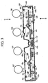
- FIG. 3 is a schematic configuration of an optical scanning unit when viewed from an axis direction of a photoconductor;
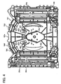
- FIG. 4 is a schematic view of lower side of an optical scanning unit in FIG. 3;
- FIG. 5 is a schematic view of upper side of an optical scanning unit in FIG. 3;
- FIG. 6 is a schematic configuration of an optical scanning unit when viewed from an axis direction of photoconductor, in which an optical scanning unit is placed on a platform of an adjustment machine;
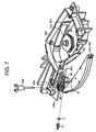
- FIG. 7 is a schematic perspective view of upper side of an optical scanning unit placed on a platform of an adjustment machine;
- FIG. 8 is a schematic perspective view of a lower side of an optical scanning unit placed on a platform of an adjustment machine;
- FIG. 9 is a schematic cross sectional view of an optical scanning unit, in which a positioning of a lens unit is shown;
- FIG. 10 is an expanded view of a cylindrical lens and a lens-receiving face, which contact each other;
- FIG. 11A is an upper perspective view of an adjusting member;
- FIG. 11B is a lower perspective view of an adjusting member;
- FIG. 12A is an upper perspective view of a lens holder;
- FIG. 12B is a lower perspective view of a lens holder;
- FIG. 13 is a schematic view for explaining a holding mechanism of a cylindrical lens in a lens holder;
- FIGs. 14A and 14B are example perspective views of a fastening member configuring a retaining mechanism;
- FIG. 15 is a schematic view explaining an arrangement of a cylindrical lens and a light source.
- The accompanying drawings are intended to depict example embodiments of the present invention and should not be interpreted to limit the scope thereof. The accompanying drawings are not to be considered as drawn to scale unless explicitly noted.
- It will be understood that if an element or layer is referred to as being "on," "against," "connected to" or "coupled to" another element or layer, then it can be directly on, against connected or coupled to the other element or layer, or intervening elements or layers may be present. In contrast, if an element is referred to as being "directly on", "directly connected to" or "directly coupled to" another element or layer, then there are no intervening elements or layers present. Like numbers refer to like elements throughout. As used herein, the term "and/or" includes any and all combinations of one or more of the associated listed items.
- Spatially relative terms, such as "beneath", "below", "lower", "above", "upper" and the like, may be used herein for ease of description to describe one element or feature's relationship to another element(s) or feature(s) as illustrated in the figures. It will be understood that the spatially relative terms are intended to encompass different orientations of the device in use or operation in addition to the orientation depicted in the figures. For example, if the device in the figures is turned over, elements described as "below" or "beneath" other elements or features would then be oriented "above" the other elements or features. Thus, term such as "below" can encompass both an orientation of above and below. The device may be otherwise oriented (rotated 90 degrees or at other orientations) and the spatially relative descriptors used herein interpreted accordingly.
- Although the terms first, second, etc. may be used herein to describe various elements, components, regions, layers and/or sections, it should be understood that these elements, components, regions, layers and/or sections should not be limited by these terms. These terms are used only to distinguish one element, component, region, layer or section from another region, layer or section. Thus, a first element, component, region, layer or section discussed below could be termed a second element, component, region, layer or section without departing from the teachings of the present invention.
- The terminology used herein is for the purpose of describing particular embodiments only and is not intended to be limiting of the present invention. As used herein, the singular forms "a", "an" and "the" are intended to include the plural forms as well, unless the context clearly indicates otherwise. It will be further understood that the terms "includes" and/or "including", when used in this specification, specify the presence of stated features, integers, steps, operations, elements, and/or components, but do not preclude the presence or addition of one or more other features, integers, steps, operations, elements, components, and/or groups thereof.
- In describing example embodiments shown in the drawings, specific terminology is employed for the sake of clarity. However, the present disclosure is not intended to be limited to the specific terminology so selected and it is to be understood that each specific element includes all technical equivalents that operate in a similar manner.
- Referring now to the drawings, wherein like reference numerals designate identical or corresponding parts throughout the several views, an image forming apparatus according to an example embodiment is described with particular reference to FIG. 1.
- FIG. 1 is a schematic cross-sectional view of an image forming apparatus 1 according to an example embodiment. The image forming apparatus 1 may include a printer having a tandem arrangement and intermediate transfer method, but the image forming apparatus 1 may not be limited to such printer but may include other applications.
- As show in FIG. 1, the image forming apparatus 1 may include a
sheet cassette 2,image forming units intermediate transfer unit 5, and a fixing unit 6, for example. - The
sheet cassette 2 may be withdrawable from the image forming apparatus 1. - The
image forming units - FIG. 2 is a schematic cross-sectional view of the
image forming unit 3Y. Theimage forming units - As shown in FIGs. 1 and 2, the
image forming units - The
image forming units charge units units units photoconductors - The
photoconductors photoconductors - For example, each of the photoconductors 10Y, 10C, 10M, and 10K may be made of a cylinder, made of aluminum having a given diameter (e.g., 40 mm), and a photosensitive layer formed on the cylinder. The photosensitive layer may include an organic photo conductor (OPC), for example.
- The
charge units - The developing
units photoconductors - The
cleaning units photoconductors - The optical writing unit 4, provided under the
image forming units
The optical writing unit 4 may be used as optical scanning unit. - The
intermediate transfer unit 5, provided over theimage forming units intermediate transfer belt 20, to which toner images are transferred from theimage forming units - The fixing unit 6 may fix the toner images on a transfer sheet P, which receives the toner images from the
intermediate transfer belt 20. - The image forming apparatus 1 may further include
toner bottles intermediate transfer unit 5 as shown in FIG. 1. Thetoner bottles toner bottles ejection tray 8 of the image forming apparatus 1. - The optical writing unit 4 may include a light source (e.g., laser diode) and a polygon mirror, for example.
- The light source may emit the laser beam L, and the polygon mirror deflects the laser beam L. Then, the deflected laser beam L may scan surfaces of the photoconductors 10Y, 10C, 10M, and 10K. The optical writing unit 4 will be explained in detail later.
- In the
intermediate transfer unit 5, theintermediate transfer belt 20 may be extended by adrive roller 21, atension roller 22, and a drivenroller 23, and may be rotated in a counter-clockwise direction in FIG. 1 at a given timing. - As shown in FIG. 1, the
intermediate transfer unit 5 may includeprimary transfer rollers photoconductors intermediate transfer belt 20. - As shown in FIG. 1, the
intermediate transfer unit 5 may further include asecondary transfer roller 25, which may transfer the toner images from theintermediate transfer belt 20 to the transfer sheet P. - The
intermediate transfer unit 5 may further include a belt-cleaningunit 26, which may remove toners remaining on theintermediate transfer belt 20 after the toner images are transferred from theintermediate transfer belt 20 to the transfer sheet P. - Hereinafter, an image forming process in the image forming apparatus 1 is explained.
- At first, the
charge units - Then, the optical writing unit 4 may scan the surfaces of the photoconductors 10Y, 10C, 10M, and 10K with the laser beam L, based on original image information, to form latent images on the surfaces of the photoconductors 10Y, 10C, 10M, and 10K.
- The latent images formed on the surfaces of the photoconductors 10Y, 10C, 10M, and 10K may be developed as toner image by supplying toners from developing
rollers 15Y, 15C, 15M, and 15K in the developingunits - The toner images formed on the
photoconductors intermediate transfer belt 20, rotating in a counter-clockwise direction in FIG. 1, with an effect of theprimary transfer rollers - The
primary transfer rollers intermediate transfer belt 20. - After such primary transfer operation, each surface of the photoconductors 10Y, 10C, 10M, and 10K may be cleaned by a
cleaning blade 13a of thecleaning units photoconductors - Toners stored in
toner bottles units image forming units - The transfer sheet P in the
sheet cassette 2 may be fed to paired-registration rollers 28 in the image forming apparatus 1 by afeed roller 27, provided near thesheet cassette 2. - The paired-
registration rollers 28 may feed the transfer sheet P to thesecond transfer roller 25 at a given timing so that the toner images can be transferred from theintermediate transfer belt 20 to the transfer sheet P. - Then, the transfer sheet P may be transported to the fixing unit 6 to fix toner images on the transfer sheet P, and then the transfer sheet P may be ejected to the
ejection tray 8 by anejection roller 29. - After the toner images are transferred from the
intermediate transfer belt 20 to the transfer sheet P, the belt-cleaningunit 26 may remove toners remaining on theintermediate transfer belt 20. - Hereinafter, the optical writing unit 4 is explained in detail.
- FIG. 3 is a schematic configuration of the optical scanning unit 4 when viewed from an axis direction of
photoconductor 10. FIG. 4 is a schematic view of lower side of the optical scanning unit 4, viewed from a direction of arrow B in FIG. 3. FIG. 5 is a schematic view of upper side of the optical writing unit 4, viewed from a direction of arrow C in FIG. 3. - In an example embodiment, the optical writing unit 4 may include
light source units - Each of the
light source units photoconductors - As shown in FIG. 3, the optical writing unit 4 may include polygon mirrors 41a and 41b, which have a regular polygonal shape such as hexagonal shape when viewed from an axis direction of polygon mirror.
- Each of the polygon mirrors 41a and 41b may have a plurality of side faces used as reflecting mirror, and may be rotated at a higher speed by a polygon motor (not shown) such as 32,000 rpm (revolution per minute), for example.
- The optical writing unit 4 may further include
lens units - As shown in FIG. 4, the
lens units light source unit lens units - As shown in FIG. 3, 4, and 5, the optical writing unit 4 may include
heat insulating glasses heat insulating glasses - The optical writing unit 4 may further include f-
theta lens first mirrors second mirrors third mirrors lens - The f-
theta lens - The
first mirrors second mirrors third mirrors lens - The optical writing unit 4 may further include dust-
proof glasses proof glasses - As shown in FIGs. 3 to 5, the optical writing unit 4 may include a
housing 100 for containing the above-mentioned parts. - Specifically, as shown in FIG. 4, the
light source units support plate 100a of thehousing 100. - Furthermore, the lower side of the
support plate 100a may be attached with thelens units cylindrical lens 61, f-theta lenses first mirrors - Furthermore, the lower side of the
support plate 100a may be attached with the long-shapedlens 50a for Y color and long-shapedlens 50d for K color. - On one hand, an upper side of the
support plate 100a may be attached with a long-shapedlens 50c for M color and a long-shapedlens 50b for C color. - The long-shaped
lens lens housing 100. The long-shapedlens lens - The long-shaped
lens 50a for K color may be fixed on the upper side face of thesupport plate 100a directly. - With such configuration, in an example embodiment, an outgoing angle of writing beam (or scanning light beam) from the long-shaped
lens - Furthermore, the
second mirrors third mirrors housing 100, which may be over the upper side of thesupport plate 100a as shown in FIG. 3. - Furthermore, as shown in FIG. 3, the
support plate 100a may include a dented portion to install the polygon mirrors 41a and 41b. The dented portion may be referred ascontainer 110, hereinafter. - As shown in FIG. 4, the
container 110 may have theheat insulating glass 42 on side walls of thecontainer 110, wherein theheat insulating glass 42 may be disposed between the polygon mirrors 41a, 41b and thelens units - The polygon mirrors 41a and 41b may be attached to the
container 110 with a screw, for example. - As shown in FIG. 3, the
housing 100 may include anupper cover 120 and alower cover 130. - The
upper cover 120 may be attached on an upper side of thehousing 100, and thelower cover 130 may be attached on a lower side of thehousing 100. - As shown in FIG. 3, the
upper cover 120 may be provided with openings to pass through the writing beam Ly, Lc, Lm, and Lk to thephotoconductors dustproof glasses - The
housing 100, covered by theupper cover 120 andlower cover 130, may reduce an intrusion of dust into the optical writing unit 4, by which optical parts in the optical writing unit 4 such as lens and mirror may be less likely to be contaminated by dust such as toner particles. - The
upper cover 120 andlower cover 130 may be made of resinous material, sheet metal, or the like, for example. - The optical writing unit 4 may have the
light source units - Such original image data may be input to the image forming apparatus 1 from a scanner (not shown), personal computer or the like, for example.
- Then, the writing beams Ly, Lc, Lm, and Lk may pass through a collimate lens (not shown) and an aperture (not shown) provided on a wall of the
housing 100. - After passing through the aperture, the writing beams Ly, Lc, Lm, and Lk may pass through the
cylindrical lens 61 of thelens units heat insulating glass 42, and may enter a reflection face of the polygon mirrors 41a and 41b. - The writing beams Ly, Lc, Lm, and Lk may be deflected by the polygon mirrors 41a and 41b, rotated by the polygon motor. Such writing beams Ly, Lc, Lm, and Lk may be used as scanning light beam for scanning each of the photoconductors 10Y, 10C, 10M, and 10K.
- Then, the writing beams (or scanning light beams) Ly, Lc, Lm, and Lk may pass through the f-
theta lenses - The writing beams Lk for K color may pass through the long-shaped
lens 50d, and then may reflect on thefirst lens 44d,second lens 46d,third lens 47d, and then may pass through thedustproof glass 48d. Then, the writing beams Lk may scan thephotoconductor 10K to form a latent image for K color on thephotoconductor 10K. - In a similar way, the writing beams Ly for Y color may pass through the long-shaped
lens 50a, and then may reflect on thefirst lens 44a,second lens 46a,third lens 47a, and then may pass through thedustproof glass 48a. Then, the writing beams Ly may scan thephotoconductor 10Y to form a latent image for Y color on thephotoconductor 10Y. - The writing beam Lm for M color may pass through the long-shaped
lens 50c via thefirst lens 44c, and then may reflect on thesecond lens 46c,third lens 47c, and may pass through thedustproof glass 48c. Then, the writing beams Lm may scan the photoconductor 10M to form a latent image for M color on thephotoconductor 10M. - In a similar way, the writing beam Lc for C color may pass through the long-shaped
lens 50b via thefirst lens 44b, and then may reflect on thesecond lens 46b,third lens 47b, and may pass through thedustproof glass 48b. Then, the writing beams Lc may scan the photoconductor 10C to form a latent image for C color on the photoconductor 10C. - Hereinafter, an adjustment work for adjusting position of
cylindrical lens 61 in its light-axis direction is explained. - FIG. 6 is a schematic configuration of the optical scanning unit 4 when viewed from an axis direction of
photoconductor 10, in which the optical scanning unit 4 is placed on theplatform 200 of an adjustment machine (not shown). - In an example embodiment, the optical writing unit 4 may be placed on the
platform 200 with a posture or orientation, which is substantially similar to a posture or orientation of the optical writing unit 4 installed in the image forming apparatus 1 (see FIGs. 1 and 3). - After placing the optical writing unit 4 on the
platform 200 with such posture or orientation,light detectors - Specifically, the
light detectors - In other words, the
light detectors - The
light detectors - Specifically, as one example, three detectors may be used for
light detector 201Y: one detector may be disposed at an each end portion of the axis direction ofphotoconductor 10Y, and one detector may be disposed at a center portion of the axis direction ofphotoconductor 10Y. Although thephotoconductor 10Y may not exist in a configuration in FIG. 6, the phrase of "axis direction ofphotoconductor 10Y" may be used for the clarity of explaining of the positions of thelight detector 201Y. - As similar to the
light detector 201Y, three detectors may be used for each oflight detectors - As shown in FIG. 6, the
light detectors control unit 202 of the adjustment machine. - The
light detectors control unit 202 as detection signal. - The
control unit 202 may conduct a plurality of computations based on received detection signal and may continuously display information, corresponding to the detection signal, on adisplay unit 203 with a substantially real time manner. - For example, the
control unit 202 may receive detection signals (e.g., corresponding to light-intensity and beam-spot diameter detected by thelight detectors light detectors display unit 203 as lens-position-adjustment information with a substantially real time manner. - With such configuration, a maintenance person can conduct an adjustment work for adjusting a position of
cylindrical lens 61 to an appropriate position while checking or looking up the lens-position-adjustment information displayed on thedisplay unit 203. - FIG. 7 is a schematic perspective view of upper side of the optical scanning unit 4 placed on the
platform 200 of the adjustment machine, in which a plurality of parts related to a light path such aslight source unit 70 and polygon mirrors 41a and 41b are shown. - FIG. 8 is a schematic perspective view of lower side of the optical scanning unit 4 placed on the
platform 200 of the adjustment machine. - In FIGs. 7 and 8, some portions of the
support plate 100a of thehousing 100 may be omitted from the drawing for the purpose of simplicity of explanation. - Furthermore, because the
lens units lens unit 60 may be used hereinafter for the purpose of simplicity of explanation. - In an example embodiment, the optical writing unit 4 may be placed on the
platform 200 of the adjustment machine with a posture or orientation, which is substantially similar to a posture or orientation when the optical writing unit 4 is installed in the image forming apparatus 1 (see FIGs. 1 and 3). - Accordingly, the
light source unit 70,collimate lens 71,cylindrical lens 61 on thelens unit 60 may be positioned on a lower side of thesupport plate 100a of thehousing 100 as shown in FIGs. 7 and 8. - As shown in FIGs. 7 and 8, the
lens unit 60 may include alens holder 62 for holdingcylindrical lens 61, and alens adjuster 63, for example. - The
lens adjuster 63 may be used to adjust a movement of thelens holder 62 in a light-axis direction of thecylindrical lens 61. - The
lens adjuster 63 may include an adjustingmember 63a, which is provided on an upper side of thesupport plate 100a, wherein a maintenance person may operate the adjustingmember 63a with adriver 160. - As shown in FIGs. 7 and 8, the
lens holder 62 may be placed on the lower side of thesupport plate 100a, and the adjustingmember 63a may be placed on the upper side of thesupport plate 100a. - In an example embodiment, a maintenance person may rotate the adjusting
member 63a with thedriver 160 to move thelens holder 62 in a light-axis direction of thecylindrical lens 61, which is indicated by an arrow D in FIG. 8. Such configuration and movement will be explained later in detail. - In general, an adjustment work for adjusting a position of the
cylindrical lens 61 in its light-axis direction at an appropriate position may need to be conducted with a highly precise manner. - Therefore, it is preferable to make an adjustment work for positioning the
cylindrical lens 61 into an easier and simplified work. - In an example embodiment, the adjusting
member 63a may be positioned on the upper side of thesupport plate 100a as shown in FIGs. 7 and 8. - Accordingly, a maintenance person can operate the adjusting
member 63a with thedriver 160 from an upper side of thesupport plate 100a. - Therefore, the maintenance person may operate the adjusting
member 63a with an easier manner compared to a hypothetical configuration (not shown) that the adjustingmember 63a may be positioned at the lower side of thesupport plate 100a. - Furthermore, in a configuration according to an example, the
cylindrical lens 61 may be positioned at the lower side face of thesupport plate 100a as shown in FIGs. 7 and 8 when the maintenance person may conduct an adjustment work. - Accordingly, an incident light, which may enter the
cylindrical lens 61, and an outgoing light, which may outgo from thecylindrical lens 61, may pass or go through an underside of thesupport plate 100a. - Therefore, the maintenance person, using the
driver 160 for operating the adjustingmember 63a, may not block a light-path for the incident light and outgoing light of thecylindrical lens 61 with thedriver 160. - With such configuration, when the maintenance person conducts an adjustment work for positioning the
cylindrical lens 61 in its light-axis direction, the maintenance person may conduct following operations with an easier and effective manner as below. - Specifically, the maintenance person may rotate the adjusting
member 63a with thedriver 160 while checking or looking-up the lens-position-adjustment information displayed on thedisplay unit 203 to find an appropriate positioning of thecylindrical lens 61 in its light-axis direction. - Accordingly, a working efficiency of the adjustment work for the
cylindrical lens 61 may be enhanced. - In an example embodiment, the optical writing unit 4 may be placed on the
platform 200 of the adjustment machine as shown in FIG. 6 when to conduct an adjustment work of thecylindrical lens 61 in its light-axis direction. - Under such configuration shown in FIG. 6, the polygon mirrors 41a and 41b may deflect a scanning light beam. Then, such scanning light beam may reflect at the
first mirrors second mirrors third mirrors - With such reflection at the mirrors, such scanning light beam may pass through the upper side of the
support plate 100a (see FIG. 6) and then reaches thelight detectors - Depending on a positional relationship of the adjusting
member 63a and a light-path for the optical writing unit 4, such scanning light beam may happened to be partially blocked by thedriver 160. - However, in an example embodiment, the light detector 201 may not detect the scanning light beam in an entire length of the axial direction of the
photoconductor 10, but instead may detect the scanning light beam at three portions (e.g., both end portion and center portion of the photoconductor 10) as one example as above-mentioned. - Based on detection results of the light detector 201 having three detectors, lens-position-adjustment information may be displayed on the
display unit 203, and a maintenance person may conduct an adjustment work while checking or looking-up the lens-position-adjustment information. - In such configuration, the
driver 160 may block a part of the scanning light beam when conducting an adjustment work of thecylindrical lens 61. - However, such blocked portion by the
driver 160 can be set to a portion, which can avoid the light-path of scanning light beam over thesupport plate 100a. - Such space allocation can be designed for the optical scanning unit 4 because the scanning light beam may be detected at separate portions (e.g., three portions in example embodiment) in the axial direction of the
photoconductor 10 as above-mentioned, wherein such portions may be spaced apart each other. - Accordingly, when a positional relationship of adjusting
member 63a and light-path of scanning light beam may be set to a configuration that thelight detector 120 can detect scanning light beam without a blocking effect of thedriver 160 when conducting an adjustment work of thecylindrical lens 61, an maintenance person may conduct such adjustment work effectively and efficiently. - Although not shown, the
driver 160 may be inserted to the adjustingmember 63a of thelens adjuster 63 without opening theupper cover 120, for example. In such a case, theupper cover 120 may have an opening at a position over the adjustingmember 63a. Such opening may be covered by a cover (not shown) during a normal image forming operation, and may be opened when conducting the above-described adjustment work. - Hereinafter, the
lens unit 60 is explained in detail with reference to FIG. 9. FIG. 9 is a schematic cross sectional view of the optical scanning unit 4, in which a positioning of thelens unit 60 is shown. - In an example embodiment, the
lens holder 62 may hold thecylindrical lens 61 while constantly contacting a face of thecylindrical lens 61 to a lens-receivingface 100b. - As shown in FIG. 9, the lens-receiving
face 100b may be provided at a lower side of thesupport plate 100a of thehousing 100. - In an example embodiment, the lower side of the
support plate 100a may include two lens-receivingfaces 100b, formed in a parallel direction of the light-axis direction of thecylindrical lens 61, for example. - Accordingly, the two lens-receiving
faces 100b may contact with a plurality of contact faces of thecylindrical lens 61. Such plurality of contact faces of thecylindrical lens 61 may be referred as contact face of thecylindrical lens 61, hereinafter, as required. - In example embodiment, the
lens holder 62, holding thecylindrical lens 61, may be attached to thesupport plate 100a while thelens holder 62 may be movable in a light-axis direction of thecylindrical lens 61. - The
lens holder 62 may be moved in a light-axis direction of thecylindrical lens 61 shown by an arrow D in FIG. 9 by rotating the adjustingmember 63a. Such direction shown by an arrow D may be referred as light-axis direction D, hereinafter, as required. - During a movement of the
lens holder 62 in the light-axis direction D, the contact face of thecylindrical lens 61 may maintain a contact condition with the lens-receivingface 100b. - In other words, when the
lens holder 62 is moved in the light-axis direction D, thecylindrical lens 61 may contactingly and slidably move on the lens-receivingface 100b. - In example embodiment, the lens-receiving
face 100b may be preferably made with a higher precision such as fine surface finishing. - If the lens-receiving
face 100b is formed with a higher precision, thecylindrical lens 61 may be regulated and positioned by the lens-receivingface 100b in a precise manner when thelens holder 62 is moved. - Such configuration may preferably enhance a precision of light axis alignment of
light source units 70,cylindrical lens 61, and polygon mirrors 41a and 41b. - In such configuration, a lens focal line of
cylindrical lens 61 and a scanning face of polygon mirrors 41a and 41b may be precisely aligned with each other over time. - If the lens focal line of
cylindrical lens 61 and scanning face of polygon mirrors 41a and 41b may not be aligned in a precise manner with each other, an optical property of the light beam may degrade (e.g., unfavorably larger beam-spot diameter). - In an example embodiment, the lens focal line of
cylindrical lens 61 and scanning face of polygon mirrors 41a and 41b may be aligned in a preferable manner by precisely positioning thecylindrical lens 61. - In an example embodiment, the
cylindrical lens 61 may need to be precisely positioned when thecylindrical lens 61 is moved in its light-axis direction D to maintain alignment of the lens focal line ofcylindrical lens 61 and scanning face of polygon mirrors 41a and 41b at a preferable manner. - Although not shown, in a hypothetical case, an intervening part may be disposed between the
cylindrical lens 61 and the lens-receivingface 100b, wherein the lens-receivingface 100b may be used for determining the positioning of thecylindrical lens 61. - If a number of such intervening parts may become greater, dimensional error of each intervening part may be accumulated, and an assembly error of intervening parts may also be accumulated. If such error becomes greater, the
cylindrical lens 61 may not be correctly positioned. - In an example embodiment, the
cylindrical lens 61 may contact the lens-receivingface 100b (used as reference face for positioning) directly. - In other words, the
cylindrical lens 61 and lens-receivingface 100b may contact each other without interposing an intervening part therebetween. - Therefore, in an example embodiment, the
cylindrical lens 61 may be positioned with a higher precision manner compared to a configuration (not shown) having an intervening part between thecylindrical lens 61 and lens-receivingface 100b. - FIG. 10 is an expanded view of the
cylindrical lens 61 and the lens-receivingface 100b, which may contact each other. - In an example embodiment, the
cylindrical lens 61 may slidably move on the lens-receivingface 100b in the light-axis direction D shown in FIG. 10 by rotating the adjustingmember 63a with the driver 160 (see FIG. 7). - In an example embodiment, the
housing 100 and lens-receivingface 100b may be made of resinous material in view of reducing manufacturing cost. - If the
cylindrical lens 61 may have a contact face having a sharp edge portion, suchcylindrical lens 61 may scrape the lens-receivingface 100b for some amount when thecylindrical lens 61 slidably moves on the lens-receivingface 100b in the light-axis direction D in FIG. 10. - If the
cylindrical lens 61 may slidably move on the lens-receivingface 100b repeatedly, the lens-receivingface 100b may be scraped more and more, and resultantly, such scraped lens-receivingface 100b may cause a precision degradation of positioning of thecylindrical lens 61. - In view of such drawback, in an example embodiment, a edge portion of contact face of the
cylindrical lens 61 may receive a chamfering or rounding process so that the contact face of thecylindrical lens 61 may have a C-face or R-face at the edge portion, wherein the C-face may mean a chamfered face and R-face may mean a rounded face as shown in FIG. 10. - With such chamfering or rounding process to the contact face of the
cylindrical lens 61, a scraping effect of thecylindrical lens 61 to the lens-receivingface 100b may be reduced compared to a cylindrical lens having no chamfering or rounding process to its contact face. - Accordingly, even if the
cylindrical lens 61 may slidably move on the lens-receivingface 100b in the light-axis direction shown by an arrow D in FIG. 10 repeatedly, thecylindrical lens 61 may be positioned with a higher precision over time. In other words, a positioning precision of thecylindrical lens 61 may not degrade over time. - FIG. 11A is an upper perspective view of the adjusting
member 63a oflens adjuster 63, viewed from an upper side of the support plate 110a. In other words, a maintenance person may see the adjustingmember 63a oflens adjuster 63 in an angle shown in FIG. 11A. - FIG. 11B is a lower perspective view of the adjusting
member 63a oflens adjuster 63, viewed from a lower side of the support plate 110a. - FIG. 12A is an upper perspective view of the
lens holder 62, viewed from an upper side of the support plate 110a. FIG. 12B is a lower perspective view of thelens holder 62, viewed from a lower side of the support plate 110a. - As shown in FIGs. 11A and 11B, the
lens adjuster 63 may include the adjustingmember 63a, abase 63b, a center-axis shaft 63c, aneccentric shaft 63d, for example. - The
base 63b may be rotatable by a force applied to the adjustingmember 63a. - The center-
axis shaft 63c may extend from thebase 63b in a direction along the rotational center axis of thebase 63b. - The
eccentric shaft 63d may extend from thebase 63b in a direction, deviated and parallel to the rotational center axis of thebase 63b (see FIG. 11B). - As shown in FIG. 11A, the
base 63b may include the adjustingmember 63a, which receive thedriver 160, at the upper side of thebase 63b. - When the
driver 160 rotates the adjustingmember 63a, the center-axis shaft 63c may rotate around a rotational center axis of thebase 63b. - Then, the
eccentric shaft 63d may rotate eccentrically around the rotational center axis of thebase 63b. - In an example embodiment, the
lens adjuster 63 may be made of resinous material such as polyacetal resin, but not limited to polyacetal resin. - If the
lens adjuster 63 is made of resinous material such as polyacetal resin, thelens adjuster 63 may receive a relatively smaller abrasion effect by friction when an adjustment work of thecylindrical lens 61 is conducted. - As described later, the
lens adjuster 63 may contact thelens holder 62 andsupport plate 100a, by which thelens adjuster 63 may friction with thelens holder 62 andsupport member 100. - With such configuration using resinous material, an adjustment work of the
cylindrical lens 61 may be conducted with a higher precision manner over time. - As shown in FIG. 12A and 12B, the
lens holder 62 may include aholder base 62a, and alens receiver 62b, for example. - The
holder base 62a may be attached to the lower side of thesupport plate 100a. - The
lens receiver 62b may be protruded from a face of theholder base 62a as shown in FIG. 12B. - The
cylindrical lens 61 may be pressed to a contactingface 62c of thelens receiver 62b, and then be held to thelens holder 62 with a fixing member (to be explained later). - In an example embodiment, a light-outgoing face of the
cylindrical lens 61 may be pressed to the contactingface 62c. - As shown in FIGs. 12A and 12B, the
holder base 62a may include anadjustment hole 62d. - The
adjustment hole 62d may have a substantially oblong figure, which is extended in a direction perpendicular to the above-mentioned light-axis direction D. As above explained, thelens holder 62 may be moved in the light-axis direction D. - The
eccentric shaft 63d may be inserted into theadjustment hole 62d. - A width of the
adjustment hole 62d may mean a width in the light-axis direction D of theholder base 62a. Such width of theadjustment hole 62d may set to a value substantially corresponding to a dimension of theeccentric shaft 63d, or set to a value which is slightly larger than a diameter of theeccentric shaft 63d. - Furthermore, the
holder base 62a may be provided with aguide 62e protruded from theholder base 62a as shown in FIGS. 12A and 12B. - In an example embodiment, the
lens unit 60 may be assembled and attached to thesupport plate 100a as below. - At first, the
cylindrical lens 61 may be held onto thelens holder 62. - Then, the
guide 62e may be engaged to a guide hole (not shown) provided to thesupport plate 100a with a snap-fit manner. - Such guide hole, formed in the
support plate 100a may have a substantially oblong figure, which is extended in the light-axis direction D of thecylindrical lens 61. A width of the guide hole may be set to a value corresponding to a thickness of theguide 62e. - With such configuration, the
lens holder 62 may be attached to the lower side face of thesupport plate 100a as shown in FIGs. 9 and 13, and may be movable in the light-axis direction D of thecylindrical lens 61. - Then, the
lens adjuster 63 having the adjustingmember 63a may be fitted in abearing hole 100g (see FIG. 9) in thesupport plate 100a. - Specifically, the center-
axis shaft 63c of thelens adjuster 63 may be inserted into thebearing hole 100g from an upper side of thesupport plate 100a from a direction shown by an arrow E in FIG. 11A. - At this time, the
eccentric shaft 63d of thelens adjuster 63 may be inserted into theadjustment hole 62d of thelens holder 62 from a direction shown by an arrow E in FIG. 12A, by which theeccentric shaft 63d may be inserted and snap-fitted into theadjustment hole 62d. - With such process, the
lens unit 60 may be assembled and attached to thesupport plate 100a. - When the adjusting
member 63a is rotated under such configuration, thelens adjuster 63 may rotate while the center-axis shaft 63c is supported by thebearing hole 100g of thesupport plate 100a. - Then, with a rotation of the
lens adjuster 63, theeccentric shaft 63d may rotate eccentrically around the rotational center axis of thebase 63b. - Then, with a rotation of the
eccentric shaft 63d, theeccentric shaft 63d may contactingly push an inner wall of theadjustment hole 62d oflens holder 62. - Then, with such pushing movement in the
adjustment hole 62d by theeccentric shaft 63d, theguide 62e oflens holder 62 may be moved in the guide hole, formed in thesupport plate 100a. - With such process, the
lens holder 62 may move reciprocally along the light-axis direction D of thecylindrical lens 61 under the lower side of thesupport plate 100a. - In an example embodiment, the
lens holder 62 andlens adjuster 63 may be assembled to thesupport plate 100a with a snap-fit process. The snap-fit process may be preferable to reduce a time required for assembling or removing parts compared to a screw-fitting process or the like. - With such assembly process requiring less time for assembly, the
lens unit 60 may be assembled to thesupport plate 100a with an enhanced working efficiency. - Furthermore, even if the
cylindrical lens 61 may be contaminated or scratched, thecylindrical lens 61 may be replaced more easily in the above-described assembly configuration. - In an example embodiment, the adjusting
member 63a may have a shape that can be operated by thedriver 160. However, the adjustingmember 63a can take another shape such as hexagonal shape that can be operated by a wrench, for example. - Furthermore, in an example embodiment, the
lens holder 62 may have a coefficient of linear expansion of 1.0 x 10⁻⁵ (1/°C) or less, for example. - Because the
cylindrical lens 61 may be disposed closely to the polygon mirrors 41a and 41b, thelens holder 62 also be disposed closely to the polygon mirrors 41a and 41b as shown in FIG. 9. - Because the polygon motor for driving the polygon mirrors 41a and 41b may generate a relatively greater amount of heat, the
lens holder 62, disposed closely to the polygon mirrors 41a and 41b, may be susceptible to such generated heat. - If the heat generated at the polygon mirrors 41a and 41b may affect the
lens holder 62, a position of thecylindrical lens 61 may be deviated from an appropriate position. For example, such heat effect may deform the contactingface 62c of thelens holder 62. - In view of such heat effect, in an example embodiment, the
lens holder 62 may have the coefficient of linear expansion of 1.0 x 10⁻⁵ (1/°C) or less so that heat generated at the polygon mirrors 41a and 41b may not affect a positioning of thecylindrical lens 61. - In other words, such heat effect may be controlled within a practical rage for realizing an appropriate positioning of the
cylindrical lens 61. - The
lens holder 62 having the coefficient of linear expansion of 1.0 x 10⁻⁵ (1/°C) or less may be manufactured from a resinous material such as polycarbonate (PC), for example. Such resinous material may be preferable from a viewpoint of reducing manufacturing cost and enhancing mass produce-ability. - Hereinafter, a retaining mechanism for retaining the
cylindrical lens 61 in thelens holder 62 is explained. - FIG. 13 is a schematic view for explaining a retaining mechanism for retaining the
cylindrical lens 61 in thelens holder 62. FIGs. 14A and 14B are example perspective views of a fixingmember 64, which may configure the retaining mechanism. In an example embodiment, as shown in FIG. 13, the light-outgoing face of thecylindrical lens 61 may contact the contactingface 62c of thelens holder 62. - Then, as shown in FIG. 13, the light-incoming face of the
cylindrical lens 61 may be biased with the fixingmember 64 such as leaf spring with a first biasing force Fx. - With such first biasing force Fx, a position of the
cylindrical lens 61 in its light-axis direction D may be determined while pressing the light-outgoing face of thecylindrical lens 61 to the contactingface 62c. - Furthermore, the
cylindrical lens 61 may be biased toward the lower side of thesupport plate 100a with the fixingmember 64 with a second biasing force Fz. - With such second biasing force Fz, a position of the
cylindrical lens 61 in a normal line direction of thesupport plate 100a may be determined. - If an external shock may occur to the optical writing unit 4 or image forming apparatus 1, the
cylindrical lens 61 may be discontacted from the lens-receivingface 100b, and then the positioning of thecylindrical lens 61 in the normal line direction of thesupport plate 100a may be deviated from an appropriate position. - Such external shock may occur to the optical writing unit 4 or image forming apparatus 1 if a person may drop the optical writing unit 4 or image forming apparatus 1 carelessly, for example.
- In an example embodiment, the
cylindrical lens 61 may more likely to be effected by a gravity effect due to a configuration of an example embodiment, and such gravity effect may cause thecylindrical lens 61 to leave from the lens-receivingface 100b more or less. - Under such configuration, the positioning of the
cylindrical lens 61 in the normal line direction of thesupport plate 100a may be deviated from an appropriate position. - In view of such situation, in an example embodiment, the fixing
member 64 may be configured to set the second biasing force Fz effectively greater than the first biasing force Fx. - The second biasing force Fz may press the
cylindrical lens 61 toward the lens-receivingface 100b. - The first biasing force Fx may press the
cylindrical lens 61 toward the contactingface 62c of thelens receiver 62b. - Specifically, following two forces may be assumed to realize an appropriate positioning of the
cylindrical lens 61. - A first force may be defined as a total static friction of the
lens receiver 62b, fixingmember 64, andcylindrical lens 61. The first force may be generated in a light-axis direction of thecylindrical lens 61. - First force = (total static friction of members)
- A second force may be defined with the second biasing force Fz of the fixing
member 64 and a self-weight of thecylindrical lens 61. - Specifically, the second force may be defined by subtracting a self-weight of the
cylindrical lens 61 from the second biasing force Fz. - Second force = (Fz)- (self-weight of cylindrical lens 61)
- Therefore, the above-explained two forces may have a following relationship for preferably realizing an appropriate positioning of the
cylindrical lens 61. - With such relationship, even if the
cylindrical lens 61 may be discontacted from the lens-receivingface 100b, the second biasing force Fz of the fixingmember 64 may push back thecylindrical lens 61 toward the lens-receivingface 100b. - With such configuration, even if an external shock, which may discontact the
cylindrical lens 61 from the lens-receivingface 100b, may occur to the optical writing unit 4, thecylindrical lens 61 may be maintained at a contact condition with the lens-receivingface 100b. - Accordingly, a position of the
cylindrical lens 61 in the normal line direction of thesupport plate 100a may be maintained at an appropriate position. - As shown in FIG. 14A, the fixing
member 64 may have a configuration having apressing member 64a to press a center portion of bottom side of thecylindrical lens 61 toward the lens-receivingface 100b, for example. - Furthermore, as shown in FIG. 14B, the fixing
member 64 may have another configuration having twopressing members 64b to press each end portion of bottom side of thecylindrical lens 61 toward the lens-receivingface 100b, for example. - In general, the more the number of pressing members, the better the positioning of the
cylindrical lens 61 in the normal line direction of thesupport plate 100a. The number of pressing members may be determined by considering several factors. - In an example embodiment, the
lens holder 62 and fixingmember 64 may be manufactured as separate parts. However, thelens holder 62 alone may include a function similar to the fixingmember 64, as required. - Furthermore, in an example embodiment, a configuration for moving the
lens holder 62 has a following feature as shown in FIG. 9. - In recent years, an image forming apparatus may be manufactured with a concept of further miniaturization. Accordingly, each part may be preferably manufactured smaller and smaller.
- In case of configuration for moving the
lens holder 62, thelens holder 62 may need or occupy a relatively larger space. Therefore, a miniaturization of thelens holder 62 may be considered when designing a miniaturization of an optical unit and image forming apparatus. In addition, a miniaturization of thelens adjuster 63 may also be considered. - In an example, as shown in FIGs. 9 and 13, a substantially-occupying-space SP of the
lens holder 62 in the light-axis direction D may be considered because such substantially-occupying-space SP may occupy a relatively larger space under the lower side of thesupport plate 100a. - The substantially-occupying-space SP, shown by a dot line in FIGs. 9 and 13, may have a given volume, which may be determined by several designing factors. Although not shown in FIGs. 9 and 13, the substantially-occupying-space SP may have an imagined three-dimensional shape when viewing the
lens holder 62 in the light-axis direction D. For example, such imagined three-dimensional shape may be an imagined rectangular parallelepiped shape, for example. - In view of miniaturization of an optical unit and image forming apparatus, a size of the
lens holder 62 may be preferably miniaturized as much as possible, by which the substantially-occupying-space SP of thelens holder 62 may be reduced. - Under such condition, a design work may be conducted to limit a space required for
lens adjuster 63 to be within such substantially-occupying-space SP of thelens holder 62. - For example, as shown in FIG. 11B, the
lens adjuster 63 has a snap-edge 63e at the end of theeccentric shaft 63d. - If such snap-
edge 63e may not be within the substantially-occupying-space SP of the lens holder 62 (i.e., the snap-edge 63e may be out of the substantially-occupying-space SP), a miniaturization of the configuration for moving thelens holder 62 may not be realized. - In an example embodiment, a size of the snap-
edge 63e may be set within the substantially-occupying-space SP of thelens holder 62 under the lower side of thesupport plate 100a as shown in FIGs. 9 and 13. - With such designing, a configuration for moving the
lens holder 62 under the lower side of thesupport plate 100a may be preferably miniaturized, by which a space-saving of an image forming apparatus may be enhanced. - Furthermore, in an example embodiment, the
cylindrical lens 61 may be tilted for a given degrees as shown in FIG. 15 to adjust a normal line direction of a light-incoming face of thecylindrical lens 61 with respect to a direction of light beam coming form thelight source unit - In an example embodiment, a controller (not shown) may detect electric current, which runs in a laser diode in the
light source unit - Then, the controller may control the laser diode with a feedback control method based on detection results of electric current of the laser diode so that the laser diode may emit a light beam having a stabilized light intensity over time.
- If a light-beam emitting direction of the
light source unit cylindrical lens 61 may be aligned in a substantially similar direction, a reflecting light LR reflecting on the light-incoming face of thecylindrical lens 61 may enter thelight source unit - If such condition may occur, the controller may not be able to control the
light source unit light source unit - In view of such condition, in an example embodiment, the
cylindrical lens 61 may be tilted for a given degrees as shown in FIG. 15 to adjust the normal line direction of the light-incoming face thecylindrical lens 61 with respect to a direction of light beam coming form thelight source unit - Specifically, the normal line direction of the light-incoming face the
cylindrical lens 61 may be slanted with respect to the direction of light beam coming form thelight source unit - With such configuration, the reflecting light LR reflecting on the light-incoming face of the
cylindrical lens 61 may not enter thelight source unit light source unit light source unit - Furthermore, in an example embodiment, the
heat insulating glass 42 may be provided between thecylindrical lens 61 and polygon mirrors 41a and 41b. Accordingly, heat generated at the polygon mirrors 41a and 41b may not be transmitted to thecylindrical lens 61, and thereby a positioning of thecylindrical lens 61 may be effectively conducted by reducing heat effect from the polygon mirrors 41a and 41b. - Numerous additional modifications and variations are possible in light of the above teachings. It is therefore to be understood that within the scope of the appended claims, the disclosure of the present invention may be practiced otherwise than as specifically described herein.
- This application claims priority from
Japanese patent application No. 2006-003705 filed on January 11, 2006
The invention further relates to the following embodiments which are parts of the description.
Advantageous features of different embodiments can be combined with each other in one embodiment. It is further possible to omit one or more features from a specific embodiment.
The omitted one or more features are not necessary for the specific embodiment.
Preferred embodiments and/or features of the invention are indicated as follows: - Embodiment number 1. An optical scanning unit, comprising:
- a light source configured to emit a light beam; a lens configured to pass through the light beam emitted from the light source; a deflector configured to rotatably deflect the light beam coming from the lens, the deflected light beam being guided to a light receiving member; a lens holder configured to hold the lens, the lens holder being provided in a space between the light source and the deflector; a support member having a first face being faced to a vertically-downward direction and being extended in a direction from the light source to the deflector, the lens holder being movably supported by the first face of the support member; a force-generating member configured to generate a force, the force-generating member being provided to a side of a second face of the support member, the second face being opposite to the first face; and a force-transmitting member configured to transmit the force generated by the force-generating member to the lens holder to move the lens holder along the first face of support member.
-
Embodiment number 2. The optical scanning unit as indicated in embodiment number 1, wherein the lens holder, supported by the support member, is movable along the first face of the support member in a light-axis direction of the lens. - Embodiment number 3. The optical scanning unit as indicated in
embodiment number 2, wherein the lens includes a cylindrical lens configured to adjust an optical property of the light beam to be entered to the deflector, and the optical property of the light beam including a beam spot property. - Embodiment number 4. The optical scanning unit as indicated in embodiment number 1, wherein the lens holder has a substantially-occupying-space along the first face of the support member including a space for moving the lens holder, and the force-generating member and force-transmitting member are sized to be within the substantially-occupying-space of the lens holder.
-
Embodiment number 5. The optical scanning unit as indicated in embodiment number 1, wherein the force-transmitting member comprising: a base member configured to be rotatable by the force generated by the force-generating member, the base member being exposed to a side of the second face of the support member; a center-axis shaft extending from the base member along a rotational center axis of the base member; and an eccentric-axis shaft extending from the base member while deviating and parallel to the rotational center axis of the base member, and the lens holder includes an adjustment hole, having an substantially oblong figure in a direction perpendicular to a moving direction of the lens holder and a width corresponding to a dimension of the eccentric-axis shaft, the eccentric-axis shaft being inserted in the adjustment hole, and the support member includes a bearing hole, to which the center-axis shaft being inserted and supported, and the force-generating member is attached onto the base member exposed to the side of the second face of the support member. - Embodiment number 6. The optical scanning unit as indicated in
embodiment number 5, wherein the force-transmitting member is made of a resinous material, and the resinous material including polyacetal resin. - Embodiment number 7. The optical scanning unit as indicated in embodiment number 1, wherein the force-transmitting member moves the lens holder along the first face of the support member while maintaining a slidably contacting condition between a contact face of the lens and the first face of the support member, and the contact face of the lens has any one of a chamfered and rounded corner.
-
Embodiment number 8. The optical scanning unit as indicated in embodiment number 1, wherein the lens holder is provided with a fixing member to retain a contact condition of the lens and the first face of the support member, the fixing member including a first biasing portion and a second biasing portion, the first biasing portion biases the lens in a first direction, which is a direction of light-axis direction of the lens, and the second biasing portion biases the lens in a second direction, which is toward the support member and perpendicular to the first biasing direction, and a force applied from the second direction is set greater than a static friction in the first direction generated by the first biasing portion, the lens holder, and the lens. - Embodiment number 9. The optical scanning unit as indicated in embodiment number 1, wherein the lens is tilt-able to slant a normal line direction of a light-incoming face of the lens with respect to a light beam emitting direction of the light source.
-
Embodiment number 10. The optical scanning unit as indicated in embodiment number 1, wherein the lens holder has a coefficient of linear expansion of 1.0 x 10⁻⁵ (1/°C) or less. - Embodiment number 11. The optical scanning unit as indicated in embodiment number 1, further comprising a transparent member provided between the lens holder and the deflector, the transparent member being made of a heat insulating material.
- Embodiment number 12. An image forming apparatus, comprising: an image-carrying member; an optical scanning unit as indicated in embodiment number 1, configured to form a latent image on the image-carrying member with irradiating a light beam on the image-carrying member; and a developing unit configured to develop the latent image and to transfer the developed image to a recording medium.
- Embodiment number 13. A method of adjusting a position of a lens in an optical scanning unit; holding a lens with a lens holder; supporting the lens holder on a first face of a support member, the first face being faced to a vertically-downward direction; emitting a light beam to the lens, the light beam to be guided to a sensor placed on a given position; sensing an optical property of the light beam with the sensor; outputting an information for adjusting a position of the lens in the optical scanning unit based on a result at the sensing step; generating a force with a force-generating member being provided on a second face of the support member, the second face being opposite to the first face of the support member; and moving the lens holder along the first face of the support member, by checking the information at the outputting step, with the force generated at the generating step while maintaining a slidably contacting condition between the lens and the first face of the support member.
- Embodiment number 14. The method as indicated in embodiment number 13, wherein the optical scanning unit is used for an image forming apparatus.
-
Embodiment number 15. An optical scanning unit, comprising: a light source configured to emit a light beam; a lens configured to pass through the light beam emitted from the light source; deflecting means for rotatably deflecting the light beam coming from the lens, the deflected light beam being guided to a light receiving member; holding means for holding the lens, the holding means being provided in a space between the light source and the deflecting means; supporting means, having a first face being faced to a vertically-downward direction, and being extended in a direction from the light source to the deflecting means, for movably supporting the holding means on the first face of the supporting means; force-generating means for generating a force, the force-generating means being provided to a side of a second face of the support member, the second face being opposite to the first face; and force-transmitting means for transmitting the force generated by the force-generating means to the holding means to move the holding means along the first face of support member. - Embodiment number 16. An optical scanning unit, comprising: a light source configured to emit a light beam; a lens configured to pass through the light beam emitted from the light source; a deflector configured to rotatably deflect the light beam coming from the lens, the deflected light beam being guided to a light receiving member; a lens holder configured to hold the lens, the lens holder being provided in a space between the light source and the deflector; a support member having a first face being faced to a vertically-downward direction and being extended in a direction from the light source to the deflector, the lens holder being movably supported by the first face of the support member; an adjusting member configured to receive a force; and a moving mechanism configured to move the lens holder along the first face of the support member using the force received by the adjusting member; wherein the adjusting member is provided to a side of a second face of the support member, the second face being opposite to the first face.
- Embodiment number 17. The optical scanning unit as indicated in any one of embodiment number 16, wherein the adjusting member is configured to be operated by a maintenance person.
-
Embodiment number 18. The optical scanning unit as indicated in embodiment numbers 16 or 17, wherein the lens holder, supported by the support member, is movable along the first face of the support member in a light-axis direction of the lens. - Embodiment number 19. The optical scanning unit as indicated in any one of embodiment numbers 16 to 18, wherein the lens includes a cylindrical lens configured to adjust an optical property of the light beam to be entered to the deflector, and the optical property of the light beam including a beam spot property.
-
Embodiment number 20. The optical scanning unit as indicated in any one of embodiment numbers 16 to 19, wherein the lens holder has a substantially-occupying-space along the first face of the support member including a space for moving the lens holder, and the adjusting member and moving mechanism are sized to be within the substantially-occupying-space of the lens holder. -
Embodiment number 21. The optical scanning unit as indicated in any one of embodiment numbers 16 to 20, wherein the moving mechanism comprising: a base member configured to be rotatable by the force received by the adjusting member, the base member being exposed to a side of the second face of the support member; a center-axis shaft extending from the base member along a rotational center axis of the base member; and an eccentric-axis shaft extending from the base member while deviating and parallel to the rotational center axis of the base member, and the lens holder includes an adjustment hole, having an substantially oblong figure in a direction perpendicular to a moving direction of the lens holder and a width corresponding to a dimension of the eccentric-axis shaft, the eccentric-axis shaft being inserted in the adjustment hole, and the support member includes a bearing hole, to which the center-axis shaft being inserted and supported, and the adjusting member is attached onto the base member exposed to the side of the second face of the support member. -
Embodiment number 22. The optical scanning unit as indicated in any one of embodiment numbers 16 to 21, wherein the moving mechanism is made of a resinous material, and the resinous material including polyacetal resin. -
Embodiment number 23. The optical scanning unit as indicated in any one of embodiment numbers 16 to 22, wherein the moving mechanism moves the lens holder along the first face of the support member while maintaining a slidably contacting condition between a contact face of the lens and the first face of the support member, and the contact face of the lens has any one of a chamfered and rounded corner. - Embodiment number 24. The optical scanning unit as indicated in any one of embodiment numbers 16 to 23, wherein the lens holder is provided with a fixing member to retain a contact condition of the lens and the first face of the support member, the fixing member including a first biasing portion and a second biasing portion, the first biasing portion biases the lens in a first direction, which is a direction of light-axis direction of the lens, and the second biasing portion biases the lens in a second direction, which is toward the support member and perpendicular to the first direction, and a force applied from the second direction is set greater than a static friction in the first direction generated by the first biasing portion, the lens holder, and the lens.
-
Embodiment number 25. The optical scanning unit as indicated in any one of embodiment numbers 16 to 24, wherein the lens is tilt-able to slant a normal line direction of a light-incoming face of the lens with respect to a light beam emitting direction of the light source. -
Embodiment number 26. The optical scanning unit as indicated in any one of embodiment numbers 16 to 25, wherein the lens holder has a coefficient of linear expansion of 1.0 x 10⁻⁵ (1/°C) or less. -
Embodiment number 27. The optical scanning unit as indicated in any one of embodiment numbers 16 to 26, further comprising a transparent member provided between the lens holder and the deflector, the transparent member being made of a heat insulating material. -
Embodiment number 28. An image forming apparatus, comprising: an image-carrying member; an optical scanning unit as indicated in any one of embodiment numbers 16 to 27, configured to form a latent image on the image-carrying member with irradiating a light beam on the image-carrying member; and a developing unit configured to develop the latent image and to transfer the developed image to a recording medium.Embodiment number 29. The image forming apparatus as indicated in any one ofembodiment number 28, further comprising: a sensor configured to sense an optical property of the light beam. - Embodiment number 30. A method of adjusting a position of a lens in an optical scanning unit; holding a lens with a lens holder; supporting the lens holder on a first face of a support member, the first face being faced to a vertically-downward direction; emitting a light beam to the lens; receiving a force with an adjusting member being provided on a second face of the support member, the second face being opposite to the first face of the support member; and moving the lens holder along the first face of the support member, with the force received at the receiving step while maintaining a slidably contacting condition between the lens and the first face of the support member.
- Embodiment number 31. The method as indicated in any one of embodiment number 30, wherein the force received in the receiving step is applied by a maintenance person.
- Embodiment number 32. The method as indicated in any one of embodiment number 30 or 31, further comprising the following steps: guiding the light beam to a sensor placed on a given position; sensing an optical property of the light beam with the sensor; outputting an information for adjusting a position of the lens in the optical scanning unit based on a result at the sensing step; and moving the lens holder along the fist face of the support member, by checking the information at the outputting step.
- Embodiment number 33. The method as indicated in any one of embodiment numbers 30 to 32, further comprising the step of: using the optical scanning unit in an image forming apparatus.
- A further preferred embodiment and/or features of the invention is/are indicated as follows:
- An optical scanning unit includes a light source, a lens, a deflector, a lens holder, a support member, a force-generating member, and a force-transmitting member. The light source emits a light beam. The lens passes through the light beam. The deflector rotatably deflects the light beam coming from the lens. The lens holder, provided between the light source and the deflector, holds the lens. The support member has a first face faced to a vertically-downward direction, and extends in a direction from the light source to the deflector. The lens holder is movably supported by the first face of the support member. The force-generating member, provided to a second face of the support member, generates a force. The second face is opposite to the first face. The force-transmitting member transmits the force generated by the force-generating member to the lens holder to move the lens holder along the first face.
Claims (18)
- An optical scanning unit (4), comprising:a light source (70) configured to emit a light beam (L);a lens (61) configured to pass through the light beam (L) emitted from the light source (70);a deflector (41a, 41b) configured to rotatably deflect the light beam (L) coming from the lens (61), the deflected light beam (L) being guided to a light receiving member (10);a lens holder (62) configured to hold the lens (61), the lens holder (62) being provided in a space between the light source (70) and the deflector (41a, 41b);a support member (100a) having a first face being faced to a vertically-downward direction and being extended in a direction from the light source (70) to the deflector (41a, 41b), the lens holder (62) being movably supported by the first face of the support member (100a);an adjusting member (63a) configured to receive a force; anda moving mechanism (63b, 63c, 63d) configured to move the lens holder (62) along the first face of the support member (100a) using the force received by the adjusting member (63a);wherein the adjusting member is provided to a side of a second face of the support member (100a), the second face being opposite to the first face.
- The optical scanning unit (4) according to claim 1, wherein
the adjusting member (63a) is configured to be operated by a maintenance person. - The optical scanning unit (4) according to claim 1 or 2, wherein the lens holder (62), supported by the support member (100a), is movable along the first face of the support member (100a) in a light-axis direction (D) of the lens (61).
- The optical scanning unit (4) according to any one of claims 1 to 3, wherein the lens (61) includes a cylindrical lens (61) configured to adjust an optical property of the light beam (L) to be entered to the deflector (41a, 41b), and the optical property of the light beam (L) including a beam spot property.
- The optical scanning unit (4) according to any one of claims 1 to 4, wherein the lens holder (62) has a substantially-occupying-space (SP) along the first face of the support member (100a) including a space for moving the lens holder (62), and the adjusting member (63a) and moving mechanism (63b, 63c, 63d) are sized to be within the substantially-occupying-space (SP) of the lens holder (62).
- The optical scanning unit (4) according to any one of claims 1 to 5, wherein the moving mechanism (63b, 63c, 63d) comprising:a base member (63b) configured to be rotatable by the force received by the adjusting member (63a), the base member (63b) being exposed to a side of the second face of the support member (100a);a center-axis shaft (63c) extending from the base member (63b) along a rotational center axis of the base member (63b); andan eccentric-axis shaft (63d) extending from the base member (63b) while deviating and parallel to the rotational center axis of the base member (63b),
and the lens holder (62) includes an adjustment hole (62d), having an substantially oblong figure in a direction perpendicular to a moving direction (D) of the lens holder (62) and a width corresponding to a dimension of the eccentric-axis shaft (63d), the eccentric-axis shaft (63d) being inserted in the adjustment hole (62d), and
the support member (100a) includes a bearing hole (100g), to which the center-axis shaft (63c) being inserted and supported, and
the adjusting member (63a) is attached onto the base member (63b) exposed to the side of the second face of the support member (100a). - The optical scanning unit (4) according to any one of claims 1 to 6, wherein the moving mechanism (63b, 63c,63d) is made of a resinous material, and the resinous material including polyacetal resin.
- The optical scanning unit (4) according to any one of claims 1 to 7, wherein the moving mechanism (63b, 63c, 63d) moves the lens holder (62) along the first face of the support member (100a) while maintaining a slidably contacting condition between a contact face of the lens (61) and the first face of the support member (100a), and the contact face of the lens has any one of a chamfered and rounded corner.
- The optical scanning unit (4) according to any one of claims 1 to 8, wherein the lens holder (62) is provided with a fixing member (64) to retain a contact condition of the lens (61) and the first face of the support member (100a), the fixing member (64) including a first biasing portion and a second biasing portion, the first biasing portion biases the lens (61) in a first direction, which is a direction of light-axis direction (D) of the lens (61), and the second biasing portion biases the lens (61) in a second direction, which is toward the support member (100a) and perpendicular to the first direction, and a force applied from the second direction is set greater than a static friction in the first direction generated by the first biasing portion, the lens holder (62), and the lens (61).
- The optical scanning unit (4) according to any one of claims 1 to 9, wherein the lens (61) is tilt-able to slant a normal line direction of a light-incoming face of the lens (61) with respect to a light beam emitting direction (D) of the light source (70).
- The optical scanning unit (4) according to any one of claims 1 to 10, wherein the lens holder (62) has a coefficient of linear expansion of 1.0 x 10⁻⁵ (1/°C) or less.
- The optical scanning unit (4) according to any one of claims 1 to 10, further comprising a transparent member provided between the lens holder (62) and the deflector (41a, 41b), the transparent member being made of a heat insulating material.
- An image forming apparatus (1), comprising:an image-carrying member (10);an optical scanning unit (4) of any one of claims 1 to 12, configured to form a latent image on the image-carrying member (10) with irradiating a light beam (L) on the image-carrying member (10); anda developing unit (12) configured to develop the latent image and to transfer the developed image to a recording medium (P).
- The image forming apparatus (1) according to claim 13, further comprising:a sensor configured to sense an optical property of the light beam (L).
- A method of adjusting a position of a lens (61) in an optical scanning unit (4);holding a lens (61) with a lens holder (62);supporting the lens holder (62) on a first face of a support member (100a), the first face being faced to a vertically-downward direction;emitting a light beam (L) to the lens (61);receiving a force with an adjusting member (63a) being provided on a second face of the support member (100a), the second face being opposite to the first face of the support member (100a); andmoving the lens holder (62) along the first face of the support member (100a), with the force received at the receiving step while maintaining a slidably contacting condition between the lens (61) and the first face of the support member (100a).
- The method according to claim 15, wherein the force received in the receiving step is applied by a maintenance person.
- The method according to claim 15 or 16, further comprising the following steps:guiding the light beam (L) to a sensor placed on a given position;sensing an optical property of the light beam (L) with the sensor;outputting an information for adjusting a position of the lens (61) in the optical scanning unit (4) based on a result at the sensing step; andmoving the lens holder (62) along the fist face of the support member (100a), by checking the information at the outputting step.
- The method according to any one of claims 15 to 17, further comprising the step of:using the optical scanning unit (4) in an image forming apparatus (1).
Applications Claiming Priority (1)
| Application Number | Priority Date | Filing Date | Title |
|---|---|---|---|
| JP2006003705A JP4875896B2 (en) | 2006-01-11 | 2006-01-11 | Optical scanning device, image forming apparatus including the same, and lens position adjusting method |
Publications (2)
| Publication Number | Publication Date |
|---|---|
| EP1809012A1 true EP1809012A1 (en) | 2007-07-18 |
| EP1809012B1 EP1809012B1 (en) | 2014-08-20 |
Family
ID=38007956
Family Applications (1)
| Application Number | Title | Priority Date | Filing Date |
|---|---|---|---|
| EP07000495.7A Ceased EP1809012B1 (en) | 2006-01-11 | 2007-01-11 | Image forming apparatus having optical scanning unit and method of adjusting lens position in optical scanning unit |
Country Status (4)
| Country | Link |
|---|---|
| US (1) | US7593149B2 (en) |
| EP (1) | EP1809012B1 (en) |
| JP (1) | JP4875896B2 (en) |
| CN (1) | CN100476502C (en) |
Cited By (1)
| Publication number | Priority date | Publication date | Assignee | Title |
|---|---|---|---|---|
| EP2863207A4 (en) * | 2012-06-19 | 2016-03-09 | Sharp Kk | Fluorescence detection device |
Families Citing this family (11)
| Publication number | Priority date | Publication date | Assignee | Title |
|---|---|---|---|---|
| JP4965290B2 (en) * | 2007-03-16 | 2012-07-04 | 株式会社リコー | Image forming apparatus |
| JP5012349B2 (en) * | 2007-09-14 | 2012-08-29 | ブラザー工業株式会社 | Optical scanning apparatus and image forming apparatus |
| JP5219549B2 (en) * | 2008-02-22 | 2013-06-26 | キヤノン株式会社 | Optical scanning device |
| JP5219548B2 (en) * | 2008-02-22 | 2013-06-26 | キヤノン株式会社 | Optical scanning device |
| JP2011104867A (en) * | 2009-11-17 | 2011-06-02 | Fuji Xerox Co Ltd | Exposure device and image forming device |
| JP5381880B2 (en) * | 2010-04-09 | 2014-01-08 | コニカミノルタ株式会社 | Optical scanning optical device |
| JP5896215B2 (en) * | 2012-01-24 | 2016-03-30 | 株式会社リコー | Optical scanning apparatus and image forming apparatus |
| JP6519657B2 (en) * | 2015-07-30 | 2019-05-29 | 京セラドキュメントソリューションズ株式会社 | Optical scanning device, image forming apparatus |
| US9854120B2 (en) * | 2015-11-18 | 2017-12-26 | Canon Kabushiki Kaisha | Optical scanning device and image forming apparatus |
| JP2017198796A (en) * | 2016-04-26 | 2017-11-02 | キヤノン株式会社 | Holding device, measuring device, and article manufacturing method |
| TWI655855B (en) * | 2017-05-17 | 2019-04-01 | Kinpo Electronics, Inc. | Image alignment adjustment mechanism of scanning device and adjustment tool thereof |
Citations (10)
| Publication number | Priority date | Publication date | Assignee | Title |
|---|---|---|---|---|
| JPS559532A (en) | 1978-07-07 | 1980-01-23 | Ricoh Co Ltd | Position adjuster of cylindrical lens |
| JPS57144517A (en) | 1981-03-03 | 1982-09-07 | Canon Inc | Scan optical system having fall compensating function |
| US4868673A (en) | 1986-11-14 | 1989-09-19 | Asahi Kogaku Kogyo K.K. | Laser beam scanning device |
| EP0564730A1 (en) | 1992-04-09 | 1993-10-13 | Mitsubishi Rayon Co., Ltd. | Image-reading device with plastic lens array |
| US5255115A (en) | 1991-03-18 | 1993-10-19 | Hitachi, Ltd. | Optical scanning apparatus and recording apparatus using the same |
| EP0849930A2 (en) | 1996-12-18 | 1998-06-24 | Kabushiki Kaisha Toshiba | Optical scanner, image forming apparatus and image forming apparatus assembling method |
| US5774248A (en) | 1993-07-08 | 1998-06-30 | Canon Kabushiki Kaisha | Optical scanning apparatus |
| US20040105079A1 (en) | 2002-08-20 | 2004-06-03 | Takeshi Yamakawa | Image formation apparatus |
| JP2004246032A (en) | 2003-02-13 | 2004-09-02 | Ricoh Co Ltd | Optical writing device and image forming device |
| US20050248884A1 (en) | 2004-05-04 | 2005-11-10 | Seagate Technology Llc | Slider having rounded corners and edges, and method for producing the same |
Family Cites Families (19)
| Publication number | Priority date | Publication date | Assignee | Title |
|---|---|---|---|---|
| JP2528688B2 (en) | 1988-02-29 | 1996-08-28 | 日東化成株式会社 | Improved post-chlorinated vinyl chloride resin composition |
| JP3066762B2 (en) * | 1990-10-16 | 2000-07-17 | コニカ株式会社 | Image forming device |
| JPH0534618A (en) | 1991-08-02 | 1993-02-12 | Ricoh Co Ltd | Optical writing device and method of moving cylinder lens |
| JPH0654011A (en) | 1992-07-30 | 1994-02-25 | Hitachi Ltd | Digital modulation wave demodulation circuit |
| JP3320171B2 (en) * | 1993-10-28 | 2002-09-03 | キヤノン株式会社 | Ejection optical device for adjustment and focus adjustment method for scanning optical device using the same |
| JPH08304726A (en) | 1995-04-28 | 1996-11-22 | Hitachi Koki Co Ltd | Optical scanning device |
| JPH09288245A (en) | 1996-04-22 | 1997-11-04 | Sankyo Seiki Mfg Co Ltd | Optical scanner |
| JPH10215351A (en) | 1997-01-29 | 1998-08-11 | Matsushita Electric Ind Co Ltd | Light beam scanning device |
| JP3387827B2 (en) * | 1998-01-07 | 2003-03-17 | キヤノン株式会社 | Scanning optical system |
| JP3511898B2 (en) * | 1998-06-15 | 2004-03-29 | 松下電器産業株式会社 | Position detecting device and lens barrel |
| JP2000147399A (en) | 1998-11-13 | 2000-05-26 | Toshiba Corp | Exposure apparatus and image forming apparatus including this exposure apparatus |
| JP3570285B2 (en) * | 1999-03-31 | 2004-09-29 | ブラザー工業株式会社 | Lens unit and optical scanning device provided with lens unit |
| JP2001154135A (en) | 1999-11-30 | 2001-06-08 | Fuji Photo Optical Co Ltd | Optical scanner |
| JP2002221682A (en) | 2001-01-25 | 2002-08-09 | Ricoh Co Ltd | Optical scanning device |
| JP2003149575A (en) * | 2001-11-09 | 2003-05-21 | Pentax Corp | Scanning optical system |
| US7532227B2 (en) * | 2002-07-02 | 2009-05-12 | Ricoh Company, Ltd. | Optical scanner and image forming apparatus |
| JP2005326794A (en) * | 2003-11-20 | 2005-11-24 | Ricoh Co Ltd | Optical scanning apparatus and image forming apparatus |
| JP4537285B2 (en) * | 2004-07-29 | 2010-09-01 | キヤノン株式会社 | Optical scanning apparatus having scanning line curvature correction mechanism |
| JP4689434B2 (en) * | 2004-12-15 | 2011-05-25 | 株式会社リコー | Optical scanning apparatus and image forming apparatus |
-
2006
- 2006-01-11 JP JP2006003705A patent/JP4875896B2/en not_active Expired - Fee Related
-
2007
- 2007-01-10 CN CNB2007100013317A patent/CN100476502C/en not_active Expired - Fee Related
- 2007-01-11 EP EP07000495.7A patent/EP1809012B1/en not_active Ceased
- 2007-01-11 US US11/651,984 patent/US7593149B2/en not_active Expired - Fee Related
Patent Citations (10)
| Publication number | Priority date | Publication date | Assignee | Title |
|---|---|---|---|---|
| JPS559532A (en) | 1978-07-07 | 1980-01-23 | Ricoh Co Ltd | Position adjuster of cylindrical lens |
| JPS57144517A (en) | 1981-03-03 | 1982-09-07 | Canon Inc | Scan optical system having fall compensating function |
| US4868673A (en) | 1986-11-14 | 1989-09-19 | Asahi Kogaku Kogyo K.K. | Laser beam scanning device |
| US5255115A (en) | 1991-03-18 | 1993-10-19 | Hitachi, Ltd. | Optical scanning apparatus and recording apparatus using the same |
| EP0564730A1 (en) | 1992-04-09 | 1993-10-13 | Mitsubishi Rayon Co., Ltd. | Image-reading device with plastic lens array |
| US5774248A (en) | 1993-07-08 | 1998-06-30 | Canon Kabushiki Kaisha | Optical scanning apparatus |
| EP0849930A2 (en) | 1996-12-18 | 1998-06-24 | Kabushiki Kaisha Toshiba | Optical scanner, image forming apparatus and image forming apparatus assembling method |
| US20040105079A1 (en) | 2002-08-20 | 2004-06-03 | Takeshi Yamakawa | Image formation apparatus |
| JP2004246032A (en) | 2003-02-13 | 2004-09-02 | Ricoh Co Ltd | Optical writing device and image forming device |
| US20050248884A1 (en) | 2004-05-04 | 2005-11-10 | Seagate Technology Llc | Slider having rounded corners and edges, and method for producing the same |
Cited By (1)
| Publication number | Priority date | Publication date | Assignee | Title |
|---|---|---|---|---|
| EP2863207A4 (en) * | 2012-06-19 | 2016-03-09 | Sharp Kk | Fluorescence detection device |
Also Published As
| Publication number | Publication date |
|---|---|
| CN101000404A (en) | 2007-07-18 |
| US7593149B2 (en) | 2009-09-22 |
| US20070159674A1 (en) | 2007-07-12 |
| CN100476502C (en) | 2009-04-08 |
| JP2007187733A (en) | 2007-07-26 |
| EP1809012B1 (en) | 2014-08-20 |
| JP4875896B2 (en) | 2012-02-15 |
Similar Documents
| Publication | Publication Date | Title |
|---|---|---|
| EP1809012B1 (en) | Image forming apparatus having optical scanning unit and method of adjusting lens position in optical scanning unit | |
| EP1750156B1 (en) | Optical scanning device and image forming apparatus | |
| US7872664B2 (en) | Optical scanning device including shutter member that closes or opens an emission window and image forming apparatus including the optical scanning device | |
| US8823764B2 (en) | Optical writer and image forming apparatus including same | |
| EP1804135B1 (en) | Housing molding method providing a simple structure | |
| US10725289B2 (en) | Casing of optical scanning apparatus, and optical scanning apparatus | |
| US7505187B2 (en) | Optical scanning unit and image forming apparatus | |
| JP2006017881A (en) | Optical writing apparatus and image forming apparatus | |
| US8872873B2 (en) | Light scanning unit and image forming apparatus using the same | |
| EP1780566A1 (en) | Light-orientation adjusting unit, optical writing unit having light-orientation adjusting unit, and image forming apparatus having optical writing unit | |
| EP1724625B1 (en) | Optical scanning unit and image forming apparatus | |
| CN100429556C (en) | Optical scanning equipment and imaging devices | |
| JP4568649B2 (en) | Optical scanning apparatus and image forming apparatus | |
| JP5183333B2 (en) | Beam adjusting mechanism, beam scanning apparatus, image forming apparatus, and beam direction adjusting method | |
| JP4799138B2 (en) | Optical component fixing mechanism, optical scanning device, and image forming apparatus | |
| JP3933876B2 (en) | Image forming apparatus | |
| US20130135696A1 (en) | Optical scanner and image forming apparatus including same | |
| US11681239B2 (en) | Optical member, optical scanning device, and image forming device | |
| US20210173202A1 (en) | Optical scanning device and image forming apparatus | |
| JP2005246901A (en) | Cleaning method for dust-proof glass | |
| US7280130B2 (en) | Optical multi-beam scanning device and image forming apparatus | |
| JP6848293B2 (en) | Optical scanning device and image forming device | |
| JPH10254212A (en) | Optical scanning device for multicolor image forming apparatus | |
| JP5123797B2 (en) | Optical scanning apparatus, image forming apparatus, and plastic optical element | |
| JP2009169077A (en) | Exposure device with adjusting function, and image forming apparatus |
Legal Events
| Date | Code | Title | Description |
|---|---|---|---|
| PUAI | Public reference made under article 153(3) epc to a published international application that has entered the european phase |
Free format text: ORIGINAL CODE: 0009012 |
|
| AK | Designated contracting states |
Kind code of ref document: A1 Designated state(s): AT BE BG CH CY CZ DE DK EE ES FI FR GB GR HU IE IS IT LI LT LU LV MC NL PL PT RO SE SI SK TR |
|
| AX | Request for extension of the european patent |
Extension state: AL BA HR MK YU |
|
| 17P | Request for examination filed |
Effective date: 20070920 |
|
| AKX | Designation fees paid |
Designated state(s): DE ES FR GB IT |
|
| 17Q | First examination report despatched |
Effective date: 20130103 |
|
| GRAP | Despatch of communication of intention to grant a patent |
Free format text: ORIGINAL CODE: EPIDOSNIGR1 |
|
| INTG | Intention to grant announced |
Effective date: 20140422 |
|
| RIN1 | Information on inventor provided before grant (corrected) |
Inventor name: TOMITA, YASUMASA C/O RICOH COMPANY, LTD. |
|
| GRAS | Grant fee paid |
Free format text: ORIGINAL CODE: EPIDOSNIGR3 |
|
| GRAA | (expected) grant |
Free format text: ORIGINAL CODE: 0009210 |
|
| AK | Designated contracting states |
Kind code of ref document: B1 Designated state(s): DE ES FR GB IT |
|
| REG | Reference to a national code |
Ref country code: GB Ref legal event code: FG4D |
|
| REG | Reference to a national code |
Ref country code: DE Ref legal event code: R096 Ref document number: 602007038178 Country of ref document: DE Effective date: 20141002 |
|
| PG25 | Lapsed in a contracting state [announced via postgrant information from national office to epo] |
Ref country code: ES Free format text: LAPSE BECAUSE OF FAILURE TO SUBMIT A TRANSLATION OF THE DESCRIPTION OR TO PAY THE FEE WITHIN THE PRESCRIBED TIME-LIMIT Effective date: 20140820 |
|
| PG25 | Lapsed in a contracting state [announced via postgrant information from national office to epo] |
Ref country code: IT Free format text: LAPSE BECAUSE OF FAILURE TO SUBMIT A TRANSLATION OF THE DESCRIPTION OR TO PAY THE FEE WITHIN THE PRESCRIBED TIME-LIMIT Effective date: 20140820 |
|
| REG | Reference to a national code |
Ref country code: DE Ref legal event code: R097 Ref document number: 602007038178 Country of ref document: DE |
|
| PLBE | No opposition filed within time limit |
Free format text: ORIGINAL CODE: 0009261 |
|
| STAA | Information on the status of an ep patent application or granted ep patent |
Free format text: STATUS: NO OPPOSITION FILED WITHIN TIME LIMIT |
|
| 26N | No opposition filed |
Effective date: 20150521 |
|
| REG | Reference to a national code |
Ref country code: FR Ref legal event code: PLFP Year of fee payment: 10 |
|
| REG | Reference to a national code |
Ref country code: FR Ref legal event code: PLFP Year of fee payment: 11 |
|
| REG | Reference to a national code |
Ref country code: FR Ref legal event code: PLFP Year of fee payment: 12 |
|
| PGFP | Annual fee paid to national office [announced via postgrant information from national office to epo] |
Ref country code: DE Payment date: 20190123 Year of fee payment: 13 Ref country code: GB Payment date: 20190121 Year of fee payment: 13 Ref country code: FR Payment date: 20190124 Year of fee payment: 13 |
|
| PGFP | Annual fee paid to national office [announced via postgrant information from national office to epo] |
Ref country code: DE Payment date: 20190123 Year of fee payment: 13 |
|
| REG | Reference to a national code |
Ref country code: DE Ref legal event code: R119 Ref document number: 602007038178 Country of ref document: DE |
|
| GBPC | Gb: european patent ceased through non-payment of renewal fee |
Effective date: 20200111 |
|
| PG25 | Lapsed in a contracting state [announced via postgrant information from national office to epo] |
Ref country code: DE Free format text: LAPSE BECAUSE OF NON-PAYMENT OF DUE FEES Effective date: 20200801 Ref country code: GB Free format text: LAPSE BECAUSE OF NON-PAYMENT OF DUE FEES Effective date: 20200111 Ref country code: FR Free format text: LAPSE BECAUSE OF NON-PAYMENT OF DUE FEES Effective date: 20200131 |
|
| P01 | Opt-out of the competence of the unified patent court (upc) registered |
Effective date: 20230523 |