JP2017198796A - Holding device, measurement device and product manufacturing method - Google Patents
Holding device, measurement device and product manufacturing method Download PDFInfo
- Publication number
- JP2017198796A JP2017198796A JP2016088224A JP2016088224A JP2017198796A JP 2017198796 A JP2017198796 A JP 2017198796A JP 2016088224 A JP2016088224 A JP 2016088224A JP 2016088224 A JP2016088224 A JP 2016088224A JP 2017198796 A JP2017198796 A JP 2017198796A
- Authority
- JP
- Japan
- Prior art keywords
- optical element
- holding device
- elastic part
- pattern
- elastic
- Prior art date
- Legal status (The legal status is an assumption and is not a legal conclusion. Google has not performed a legal analysis and makes no representation as to the accuracy of the status listed.)
- Pending
Links
Images

Classifications
-
- G—PHYSICS
- G01—MEASURING; TESTING
- G01B—MEASURING LENGTH, THICKNESS OR SIMILAR LINEAR DIMENSIONS; MEASURING ANGLES; MEASURING AREAS; MEASURING IRREGULARITIES OF SURFACES OR CONTOURS
- G01B11/00—Measuring arrangements characterised by the use of optical techniques
- G01B11/24—Measuring arrangements characterised by the use of optical techniques for measuring contours or curvatures
- G01B11/25—Measuring arrangements characterised by the use of optical techniques for measuring contours or curvatures by projecting a pattern, e.g. one or more lines, moiré fringes on the object
-
- G—PHYSICS
- G02—OPTICS
- G02B—OPTICAL ELEMENTS, SYSTEMS OR APPARATUS
- G02B7/00—Mountings, adjusting means, or light-tight connections, for optical elements
- G02B7/008—Mountings, adjusting means, or light-tight connections, for optical elements with means for compensating for changes in temperature or for controlling the temperature; thermal stabilisation
-
- G—PHYSICS
- G02—OPTICS
- G02B—OPTICAL ELEMENTS, SYSTEMS OR APPARATUS
- G02B26/00—Optical devices or arrangements for the control of light using movable or deformable optical elements
- G02B26/08—Optical devices or arrangements for the control of light using movable or deformable optical elements for controlling the direction of light
- G02B26/0816—Optical devices or arrangements for the control of light using movable or deformable optical elements for controlling the direction of light by means of one or more reflecting elements
- G02B26/0833—Optical devices or arrangements for the control of light using movable or deformable optical elements for controlling the direction of light by means of one or more reflecting elements the reflecting element being a micromechanical device, e.g. a MEMS mirror, DMD
Abstract
Description
本発明は、保持装置、計測装置、および物品の製造方法に関する。 The present invention relates to a holding device, a measuring device, and an article manufacturing method.
物体の形状を計測する装置として、パターン投影法を用いた計測装置が知られている。パターン投影法では、パターンを物体に投影して撮像し、得られた画像におけるパターンを検出し、三角測量の原理から各画素位置における距離情報を得て、物の形状を得ている。 As a device for measuring the shape of an object, a measurement device using a pattern projection method is known. In the pattern projection method, a pattern is projected onto an object and imaged, the pattern in the obtained image is detected, distance information at each pixel position is obtained from the principle of triangulation, and the shape of the object is obtained.
投影されるパターンは、例えば、光の透過率または反射率を空間的に制御する機能を有する素子を照明光学系により照明することで生成される。生成されたパターンは、投影光学系を介して物体に投影される。投影されたパターンは、環境温度の影響で照明光学系、素子および投影光学系の間の位置関係が変化することにより、変化しうる。そのため、特許文献1の保持装置は、収納部内における素子の移動方向を一方向に規定して、温度変化に対する素子の位置の安定性を高めている The projected pattern is generated, for example, by illuminating an element having a function of spatially controlling light transmittance or reflectance with an illumination optical system. The generated pattern is projected onto the object via the projection optical system. The projected pattern can be changed by changing the positional relationship among the illumination optical system, the element, and the projection optical system due to the influence of the environmental temperature. For this reason, the holding device of Patent Document 1 regulates the movement direction of the element in the storage portion to one direction, and improves the stability of the position of the element with respect to a temperature change.
しかしながら、特許文献1に記載の保持装置は、素子と収納部との間の摩擦の影響を考慮しておらず、温度変化により素子と収納部とが膨張や収縮をした場合、それらの間に作用する摩擦力により、素子の位置の再現性の点で不利となりうる。 However, the holding device described in Patent Document 1 does not consider the influence of friction between the element and the storage unit, and when the element and the storage unit expand or contract due to a temperature change, between them, The acting frictional force can be disadvantageous in terms of reproducibility of the position of the element.
本発明は、例えば、保持される物体の位置の再現性の点で有利な保持装置を提供することを目的とする。 An object of the present invention is to provide a holding device that is advantageous in terms of the reproducibility of the position of an object to be held, for example.
上記課題を解決するために、本発明は、光学素子を保持する保持装置であって、光学素子の互いに隣接する第1側面および第2側面を位置決めする位置決め部と、位置決め部に支持され、第1側面に対向する光学素子の第3側面に付勢力を加える第1弾性部と、位置決め部に支持され、第2側面に対向する光学素子の第4側面に付勢力を加える第2弾性部と、第1弾性部と光学素子との間の線膨張量の差と、第2弾性部と光学素子との間の線膨張量の差とが、ともに閾値以下になるように、第1弾性部と第2弾性部とが構成されていることを特徴とする。 In order to solve the above-described problems, the present invention provides a holding device for holding an optical element, wherein the optical element is supported by the positioning unit, a positioning unit that positions the first side surface and the second side surface adjacent to each other, A first elastic portion that applies a biasing force to the third side surface of the optical element that faces the one side surface; a second elastic portion that is supported by the positioning portion and applies a biasing force to the fourth side surface of the optical element that faces the second side surface; The first elastic portion so that the difference in linear expansion between the first elastic portion and the optical element and the difference in linear expansion between the second elastic portion and the optical element are both equal to or less than a threshold value. And the second elastic portion.
本発明によれば、例えば、保持される物体の位置の再現性の点で有利な保持装置を提供することができる。 According to the present invention, for example, it is possible to provide a holding device that is advantageous in terms of reproducibility of the position of an object to be held.
以下、本発明を実施するための形態について図面などを参照して説明する。 Hereinafter, embodiments for carrying out the present invention will be described with reference to the drawings.
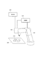
図1は本発明の第1実施形態に係る保持装置を用いた計測装置の図である。計測装置100は、パターン投影法を用いて、被検面に配置された被計測物(物体)の形状(例えば、3次元形状、2次元形状、位置及び姿勢など)を計測する。計測装置100は、図1に示すように、投影部20と、撮像部30と、処理部40とを有する。
FIG. 1 is a diagram of a measuring device using a holding device according to a first embodiment of the present invention. The
投影部20は、例えば、光源部21と、パターン生成部22と、投影光学系23とを含み、所定のパターンを被計測物に投影する。光源部21は、光源から射出された光で、パターン生成部22で生成されたパターンを均一に照明する(例えば、ケーラー照明)。パターン生成部22は、被計測物に投影するパターン(パターン光)を生成する。本実施形態では、任意のパターンを生成可能なDMD(Digital Micromirror Device)を用いる。その他、LCOS(Liquid Crystal On Silicon)、ガラス基板をクロムめっきすることによってパターンが形成されたマスク等を用いることもできる。投影光学系23は、パターン生成部22で生成されたパターンを被計測物に投影する光学系である。
The
撮像部30は、例えば、撮像素子31と、撮像光学系32とを含み、被計測物を撮像して画像を取得する。撮像光学系32は、被計測物に投影されたパターンを撮像素子31に結像するための結像光学系である。撮像素子31は、パターンが投影された被計測物を撮像するための複数の画素を含むイメージセンサであって、例えば、CMOSセンサやCCDセンサなどで構成されている。
The
処理部40は、撮像部30で取得された画像に基づいて、被計測物の形状を求める。処理部40は、制御部41と、演算部42とを含む。制御部41は、投影部20や撮像部30の動作、具体的には、被計測物へのパターンの投影やパターンが投影された被計測物の撮像などを制御する。演算部42は、取得した画像から輝度分布を求め、距離情報の算出を行う。輝度分布は、撮像部30が求めてもよい。算出方法は、例えば、空間符号化法を用いる。
The
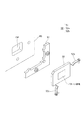
図2は、パターン生成部(光学素子)22を保持する保持装置の構成を示す図である。本実施形態では、薄い直方体のような形状のパターン生成部22を用いる。保持装置50は投影部20内において、パターン生成部22、光源部21および投影光学系23が所定の位置関係となるように配置される。保持装置50は、固定部(位置決め部)51と弾性部52とを有する。固定部51には、パターン生成部22の側面が当接する当接面(突き出し部、凸部)が少なくともひとつ突設されている。本実施形態では、パターン生成部22の角近傍にて突き出し部が当接している。弾性部52は、固定部51に取り付けられ、パターン生成部22が突き出し部に当接するようにパターン生成部22を付勢する。本実施形態では、弾性部52は、板ばね52a、52bを含む。また、保持装置50は、投影部20に設けられた支持部60に固定される。支持部60は、パターン生成部22のパターン領域が露出するような形状の開口部OPを当該パターン領域に対応する位置に有する。なお、本実施形態では、板ばね52aおよび52bの固定部51への取り付けや固定部51(保持装置50)の支持部60への固定は、ねじを用いて行う。
FIG. 2 is a diagram illustrating a configuration of a holding device that holds the pattern generation unit (optical element) 22. In the present embodiment, a
固定部51、弾性部52、および支持部60は、コストと加工性の観点から、例えば、アルミニウム(線膨張係数:23×10−6/℃)で形成する。SUS304等のオーステナイト系ステンレス鋼を用いることができる。また、パターン生成部22は非金属、例えば、アルミナセラミックス(線膨張係数:7×10−6/℃)で形成する。
The
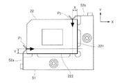
図3は、パターン生成部22の角近傍を弾性部52により付勢して固定部51へ当接させて固定した様子を示す図である。板ばね52aは、パターン生成部22の側面221が固定部51の突き出し部に当接するように、当該突き出し部と対向する対向面にある点P1にてパターン生成部22を付勢する。同様に、板ばね52bは、パターン生成部22の側面222が固定部51の突き出し部に当接するように、点P2にてパターン生成部22を付勢する。図示したように側面221と側面222とは互いに隣接する。この構成によれば、固定部51が弾性部52による付勢力を、該付勢力が作用する点と対向する面で受けるため、モーメントによりパターン生成部22が回転することが防止される。また、弾性部52による付勢力以外にも計測装置外部からの衝撃などによりモーメントが発生しうる。本実施形態では、点P1近傍のパターン生成部22の角を点P1と挟むような位置と、点P2近傍のパターン生成部22の角を点P2と挟むような位置とにそれぞれ突き出し部を設けることで外部からの衝撃による回転を防止している。
FIG. 3 is a diagram illustrating a state in which the vicinity of the corner of the
装置が設置される環境温度の変化等による、固定部51、弾性部52、支持部60、およびパターン生成部22の変形量は、板ばね52aおよび52bの弾性変形により吸収される。これにより、パターン生成部22の保持精度は維持される。また、パターン生成部22の破損も防止できる。しかしながら、上記各部材の線膨張係数の差により、各部材間で摩擦力が発生しうる。この摩擦力により、各部材の変形量が板ばね52aおよび52bの弾性変形に吸収されなくなりうる。例えば、環境温度が初期温度からある温度まで変化した後、初期温度に戻った場合に各部材が初期温度における位置に戻らなくなる。これは、パターン生成部22の保持精度(保持される物体の位置の再現性)の低下につながる。
The deformation amount of the
そこで、本実施形態では、線膨張係数の差による摩擦力を考慮して、パターン生成部22を付勢する位置を規定している。点P1の位置を、側面222と板ばね52aが付勢力を与える側面とが接続する位置(パターン生成部22の角)から距離Yだけ離れた位置とする。同様に、点P2の位置を、パターン生成部22の角から距離X離れた位置とする。例えば、環境温度の変化量をΔt℃とした場合、パターン生成部22の線膨張係数をα、支持部60、固定部51、板ばね52aおよび52bの線膨張係数をβとする。点P1でのパターン生成部22の線膨張量δp、板ばね52aの線膨張量δsは、それぞれ、δp=α×Δt×Y、δs=β×Δt×Yで示される。したがって、点P1では、パターン生成部22と板ばね52aとの間で、|δp−δs|=|α−β|×Δt×Yの相互ずれ量が発生する。パターン生成部22と板ばね52aとの間の摩擦係数が大きい場合、この相互ずれ量が板ばね52aの弾性変形に吸収されなくなりうる。
Therefore, in this embodiment, the position where the
摩擦力の影響により、最大で上記相互ずれ量に対応した変形量が弾性変形に吸収されず残留する。例えば、Δt=45℃、α=7×10⁻⁶/℃、β=23×10−6/℃とし、変形量の許容値Zを3μmとする。相互ずれ量が許容値(閾値)Z以下となる距離Yを算出すると、|δp−δs|=|α−β|×Δt×Y≦Z、すなわち、Z/(|α−β|×Δt)=3×10−6m/16×10−6×45≧Y より、Y≦4.16mmとなる。つまり、点P1を角から4.16mm以下の距離となる位置に規定することで、保持精度(保持される物体の位置の再現性)を許容範囲内(閾値以下)にすることができる。この位置は、Δt=0、すなわち温度の変化前における位置(初期位置)である。点P2に関しても同様である。 Due to the influence of the frictional force, the maximum deformation amount corresponding to the mutual displacement amount is not absorbed by the elastic deformation and remains. For example, Δt = 45 ° C., α = 7 × 10 −6 / ° C., β = 23 × 10 −6 / ° C., and the allowable value Z of deformation is 3 μm. When the distance Y at which the mutual deviation amount is equal to or smaller than the allowable value (threshold value) Z is calculated, | δp−δs | = | α−β | × Δt × Y ≦ Z, that is, Z / (| α−β | × Δt). = 3 × 10 −6 m / 16 × 10 −6 × 45 ≧ Y Therefore, Y ≦ 4.16 mm. That is, by defining the point P 1 at a position that is a distance of 4.16 mm or less from the corner, the holding accuracy (reproducibility of the position of the held object) can be within an allowable range (below the threshold). This position is Δt = 0, that is, a position (initial position) before a temperature change. The same is true with respect to the point P 2.
なお、固定部51、弾性部52、および支持部60の線膨張係数がそれぞれ異なる場合は、例えば、環境温度の変化前後の点P1の位置変化量と環境温度の変化量から線膨張係数に相当する値を求めて、上記と同様に点P1の適切な位置を算出することができる。
The fixed
以上のように、本実施形態の保持装置は、パターン生成部22を付勢する位置を、パターン生成部22と弾性部52との線膨張係数差および環境温度の変化量から求めた位置とすることで所定の保持精度を得ることができる。本実施形態によれば、保持される物体の位置の再現性の点で有利な保持装置を提供することができる。
As described above, in the holding device according to the present embodiment, the position for energizing the
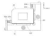
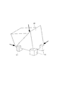
なお、弾性部52として、図4に示すような、パターン生成部22の側面に接する押圧部521aを備えた圧縮ばね522a、および押圧部521bを備えた圧縮ばね522bを用いることもできる。また、パターン生成部22は、薄い直方体のような形状の部材に限られず、例えば、図5に示すプリズムのような多面体の部材であってもよい。この場合は、矢印の方向に当該部品を付勢する。弾性部52がパターン生成部22を面で付勢する場合は、当該面の中心または重心を付勢位置とする。
In addition, as the elastic part 52, as shown in FIG. 4, the
(物品製造方法に係る実施形態)
上述の保持装置を備えた計測装置は、ある支持部材に支持された状態で使用されうる。本実施形態では、一例として、図6のようにロボットアーム300(把持装置)に備え付けられて使用される制御システムについて説明する。計測装置100は、支持台200に置かれた被検物210にパターン光を投影して撮像し、画像を取得する。そして、計測装置100の制御部が、又は、計測装置100の制御部から画像データを取得した制御部310が、被検物210の位置および姿勢を求め、その結果、当該位置および姿勢の情報を制御部310が取得する。制御部310は、その位置および姿勢の情報(計測結果)に基づいて、ロボットアーム300に駆動指令を送ってロボットアーム300を制御する。ロボットアーム300は先端のロボットハンドなど(把持部)で被検物210を保持して、並進や回転などの移動をさせる。さらに、ロボットアーム300によって被検物210を他の部品に組み付ける(組立する)ことにより、複数の部品で構成された物品、例えば電子回路基板や機械などを製造することができる。また、移動された被検物210を加工することにより、物品を製造することができる。制御部310は、CPUなどの演算装置やメモリなどの記憶装置を有する。なお、ロボットを制御する制御部を制御部310の外部に設けても良い。また、計測装置100により計測された計測データや得られた画像をディスプレイなどの表示部320に表示してもよい。
(Embodiment related to article manufacturing method)
A measuring device provided with the above-mentioned holding device can be used in a state of being supported by a certain support member. In the present embodiment, as an example, a control system that is provided and used in a robot arm 300 (gripping device) as shown in FIG. 6 will be described. The measuring
(その他の実施形態)
以上、本発明の好ましい実施形態について説明したが、本発明は、これらの実施形態に限定されず、その要旨の範囲内で種々の変形および変更が可能である。
(Other embodiments)
As mentioned above, although preferable embodiment of this invention was described, this invention is not limited to these embodiment, A various deformation | transformation and change are possible within the range of the summary.
22 パターン生成部
50 保持装置
51 固定部(位置決め部)
52 弾性部
52a、52b 板ばね
22
52
Claims (10)
前記光学素子の互いに隣接する第1側面および第2側面を位置決めする位置決め部と、
前記位置決め部に支持され、前記第1側面に対向する前記光学素子の第3側面に付勢力を加える第1弾性部と、
前記位置決め部に支持され、前記第2側面に対向する前記光学素子の第4側面に付勢力を加える第2弾性部と、
前記第1弾性部と前記光学素子との間の線膨張量の差と、前記第2弾性部と前記光学素子との間の線膨張量の差とが、ともに閾値以下になるように、前記第1弾性部と前記第2弾性部とが構成されていることを特徴とする保持装置。 A holding device for holding an optical element,
A positioning part for positioning the first side surface and the second side surface adjacent to each other of the optical element;
A first elastic portion that is supported by the positioning portion and applies a biasing force to a third side surface of the optical element facing the first side surface;
A second elastic portion that is supported by the positioning portion and applies a biasing force to the fourth side surface of the optical element facing the second side surface;
The difference in linear expansion between the first elastic part and the optical element and the difference in linear expansion between the second elastic part and the optical element are both equal to or less than a threshold value. A holding device comprising a first elastic part and the second elastic part.
Z/(|α−β|×Δt)
で得られる値以下であることを特徴とする請求項1に記載の保持装置。 Assuming that the linear expansion coefficient of the optical element is α, the linear expansion coefficient of the first elastic part is β, the amount of change in temperature is Δt, and the threshold is Z, the first elastic part applies the biasing force to the optical element. The distance from the second side of the initial position to be added is
Z / (| α−β | × Δt)
The holding device according to claim 1, wherein the holding device is equal to or less than a value obtained by the following.
Z/(|α−β|×Δt)
で得られる値以下であることを特徴とする請求項1に記載の保持装置。 Assuming that the linear expansion coefficient of the optical element is α, the linear expansion coefficient of the second elastic part is β, the amount of temperature change is Δt, and the threshold is Z, the second elastic part applies the biasing force to the optical element. The distance from the first side surface of the initial position to be added is
Z / (| α−β | × Δt)
The holding device according to claim 1, wherein the holding device is equal to or less than a value obtained by the following.
前記光学素子を保持する請求項1乃至7のうちいずれか1項に記載の保持装置を有することを特徴とする計測装置。 A measuring apparatus that includes an optical element, projects a pattern onto the object via the optical element, and measures the object by imaging the object on which the pattern is projected;
A measuring apparatus comprising the holding device according to claim 1 that holds the optical element.
前記計測装置による計測を行われた前記物体の移動を行うロボットと、
を有するシステム。 A measuring device according to claim 8;
A robot that moves the object measured by the measuring device;
Having a system.
前記工程で前記移動を行われた前記物体を処理する工程と、
を含むことを特徴とする物品の製造方法。 A step of moving an object measured by the measuring device according to claim 8 by a robot;
Processing the object that has been moved in the step;
A method for producing an article comprising:
Priority Applications (2)
| Application Number | Priority Date | Filing Date | Title |
|---|---|---|---|
| JP2016088224A JP2017198796A (en) | 2016-04-26 | 2016-04-26 | Holding device, measurement device and product manufacturing method |
| US15/496,169 US10359275B2 (en) | 2016-04-26 | 2017-04-25 | Holding apparatus, measurement apparatus, and article manufacturing method |
Applications Claiming Priority (1)
| Application Number | Priority Date | Filing Date | Title |
|---|---|---|---|
| JP2016088224A JP2017198796A (en) | 2016-04-26 | 2016-04-26 | Holding device, measurement device and product manufacturing method |
Publications (2)
| Publication Number | Publication Date |
|---|---|
| JP2017198796A true JP2017198796A (en) | 2017-11-02 |
| JP2017198796A5 JP2017198796A5 (en) | 2019-05-30 |
Family
ID=60090058
Family Applications (1)
| Application Number | Title | Priority Date | Filing Date |
|---|---|---|---|
| JP2016088224A Pending JP2017198796A (en) | 2016-04-26 | 2016-04-26 | Holding device, measurement device and product manufacturing method |
Country Status (2)
| Country | Link |
|---|---|
| US (1) | US10359275B2 (en) |
| JP (1) | JP2017198796A (en) |
Cited By (2)
| Publication number | Priority date | Publication date | Assignee | Title |
|---|---|---|---|---|
| WO2022024325A1 (en) * | 2020-07-30 | 2022-02-03 | 三菱電機株式会社 | Optical component unit, optical unit, distance measuring device, and method for manufacturing optical unit |
| WO2024061594A1 (en) * | 2022-09-20 | 2024-03-28 | Carl Zeiss Smt Gmbh | Holding device for an optical component having an optical surface with a polygonal border and having a cylindrical substrate body |
Families Citing this family (2)
| Publication number | Priority date | Publication date | Assignee | Title |
|---|---|---|---|---|
| CN108051880B (en) * | 2017-12-08 | 2020-01-21 | 苏州大学 | Method for processing metal multi-face scanning prism |
| CN108050959B (en) * | 2017-12-12 | 2020-01-21 | 苏州大学 | On-line detection system for metal multi-surface scanning prism processing |
Citations (4)
| Publication number | Priority date | Publication date | Assignee | Title |
|---|---|---|---|---|
| JP2000089363A (en) * | 1998-06-26 | 2000-03-31 | Matsushita Electric Ind Co Ltd | Projector |
| JP2003233125A (en) * | 2001-12-07 | 2003-08-22 | Victor Co Of Japan Ltd | Projection type display device |
| JP2004205917A (en) * | 2002-12-26 | 2004-07-22 | Victor Co Of Japan Ltd | Projection type display device |
| JP2010243686A (en) * | 2009-04-03 | 2010-10-28 | Konica Minolta Opto Inc | Image projecting device and method for detecting pixel deviation amount |
Family Cites Families (6)
| Publication number | Priority date | Publication date | Assignee | Title |
|---|---|---|---|---|
| JP2002365612A (en) | 2001-06-05 | 2002-12-18 | Sony Corp | Holding device for liquid crystal display element, and projection type image display device having holding device for liquid crystal display element |
| JP2003161701A (en) | 2001-11-28 | 2003-06-06 | Olympus Optical Co Ltd | Lighting system |
| JP4875896B2 (en) * | 2006-01-11 | 2012-02-15 | 株式会社リコー | Optical scanning device, image forming apparatus including the same, and lens position adjusting method |
| JP5460341B2 (en) | 2010-01-06 | 2014-04-02 | キヤノン株式会社 | Three-dimensional measuring apparatus and control method thereof |
| JP2013068774A (en) * | 2011-09-22 | 2013-04-18 | Sony Corp | Optical device and projection apparatus |
| JP2017203871A (en) | 2016-05-11 | 2017-11-16 | キヤノン株式会社 | Retainer, measuring device, and article manufacturing method |
-
2016
- 2016-04-26 JP JP2016088224A patent/JP2017198796A/en active Pending
-
2017
- 2017-04-25 US US15/496,169 patent/US10359275B2/en not_active Expired - Fee Related
Patent Citations (4)
| Publication number | Priority date | Publication date | Assignee | Title |
|---|---|---|---|---|
| JP2000089363A (en) * | 1998-06-26 | 2000-03-31 | Matsushita Electric Ind Co Ltd | Projector |
| JP2003233125A (en) * | 2001-12-07 | 2003-08-22 | Victor Co Of Japan Ltd | Projection type display device |
| JP2004205917A (en) * | 2002-12-26 | 2004-07-22 | Victor Co Of Japan Ltd | Projection type display device |
| JP2010243686A (en) * | 2009-04-03 | 2010-10-28 | Konica Minolta Opto Inc | Image projecting device and method for detecting pixel deviation amount |
Cited By (2)
| Publication number | Priority date | Publication date | Assignee | Title |
|---|---|---|---|---|
| WO2022024325A1 (en) * | 2020-07-30 | 2022-02-03 | 三菱電機株式会社 | Optical component unit, optical unit, distance measuring device, and method for manufacturing optical unit |
| WO2024061594A1 (en) * | 2022-09-20 | 2024-03-28 | Carl Zeiss Smt Gmbh | Holding device for an optical component having an optical surface with a polygonal border and having a cylindrical substrate body |
Also Published As
| Publication number | Publication date |
|---|---|
| US10359275B2 (en) | 2019-07-23 |
| US20170307364A1 (en) | 2017-10-26 |
Similar Documents
| Publication | Publication Date | Title |
|---|---|---|
| JP7069535B2 (en) | Exposure equipment and exposure method, and device manufacturing method | |
| US10359275B2 (en) | Holding apparatus, measurement apparatus, and article manufacturing method | |
| US10379450B2 (en) | Apparatus and methods for on-the-fly digital exposure image data modification | |
| JP2019105854A5 (en) | ||
| JP7308943B2 (en) | Dynamic generation of layout-adaptive packaging | |
| JP2015065246A (en) | Optical device, optical system, exposure device, and manufacturing method for article | |
| JP2023126759A (en) | Model based dynamic positional correction for digital lithography tools | |
| TW201823882A (en) | Movable body apparatus, moving method, exposure apparatus, exposure method, manufacturing method of flat panel display, and device manufacturing method | |
| TWI781959B (en) | Movable body apparatus, moving method, exposure apparatus, exposure method, manufacturing method of flat panel display, and device manufacturing method | |
| JP4522142B2 (en) | Exposure apparatus, exposure method, and substrate manufacturing method | |
| US20170328705A1 (en) | Holding apparatus, measurement apparatus, and article manufacturing method | |
| US10114297B2 (en) | Active eye-to-eye with alignment by X-Y capacitance measurement | |
| JP4424739B2 (en) | Stage equipment | |
| CN105474104A (en) | Exposure apparatus | |
| KR20130028461A (en) | 3d shape mesurement mehod and device by using amplitude of projection grating | |
| JP6614880B2 (en) | Lithographic apparatus and article manufacturing method | |
| TW201827939A (en) | Movable body apparatus, moving method, exposure apparatus, exposure method, manufacturing method of flat panel display, and device manufacturing method | |
| KR102321780B1 (en) | Determination method, optical apparatus, projection optical system, exposure apparatus, and method of manufacturing article | |
| JP4962780B2 (en) | STAGE DEVICE, FLOAT CONTROL METHOD, AND EXPOSURE DEVICE USING STAGE DEVICE | |
| KR102319819B1 (en) | Optical device, projection optical system, exposure apparatus, and manufacturing method of article | |
| JP2019045182A (en) | Three-dimensional measurement apparatus and three-dimensional measurement method | |
| JP6298345B2 (en) | Measuring method, exposure apparatus, and article manufacturing method | |
| JP2018048938A (en) | Measurement device, system, and manufacturing method of article | |
| JP2017198758A (en) | Exposure equipment, exposure method, and device manufacturing method |
Legal Events
| Date | Code | Title | Description |
|---|---|---|---|
| A521 | Request for written amendment filed |
Free format text: JAPANESE INTERMEDIATE CODE: A523 Effective date: 20190416 |
|
| A621 | Written request for application examination |
Free format text: JAPANESE INTERMEDIATE CODE: A621 Effective date: 20190416 |
|
| A977 | Report on retrieval |
Free format text: JAPANESE INTERMEDIATE CODE: A971007 Effective date: 20191212 |
|
| A131 | Notification of reasons for refusal |
Free format text: JAPANESE INTERMEDIATE CODE: A131 Effective date: 20200107 |
|
| A02 | Decision of refusal |
Free format text: JAPANESE INTERMEDIATE CODE: A02 Effective date: 20200630 |