EP1808113B1 - Staubsauger - Google Patents
Staubsauger Download PDFInfo
- Publication number
- EP1808113B1 EP1808113B1 EP06008559.4A EP06008559A EP1808113B1 EP 1808113 B1 EP1808113 B1 EP 1808113B1 EP 06008559 A EP06008559 A EP 06008559A EP 1808113 B1 EP1808113 B1 EP 1808113B1
- Authority
- EP
- European Patent Office
- Prior art keywords
- connecting rod
- suction unit
- wheels
- suction
- vacuum cleaner
- Prior art date
- Legal status (The legal status is an assumption and is not a legal conclusion. Google has not performed a legal analysis and makes no representation as to the accuracy of the status listed.)
- Ceased
Links
Images




Classifications
-
- A—HUMAN NECESSITIES
- A47—FURNITURE; DOMESTIC ARTICLES OR APPLIANCES; COFFEE MILLS; SPICE MILLS; SUCTION CLEANERS IN GENERAL
- A47L—DOMESTIC WASHING OR CLEANING; SUCTION CLEANERS IN GENERAL
- A47L9/00—Details or accessories of suction cleaners, e.g. mechanical means for controlling the suction or for effecting pulsating action; Storing devices specially adapted to suction cleaners or parts thereof; Carrying-vehicles specially adapted for suction cleaners
- A47L9/02—Nozzles
-
- E—FIXED CONSTRUCTIONS
- E01—CONSTRUCTION OF ROADS, RAILWAYS, OR BRIDGES
- E01D—CONSTRUCTION OF BRIDGES, ELEVATED ROADWAYS OR VIADUCTS; ASSEMBLY OF BRIDGES
- E01D2/00—Bridges characterised by the cross-section of their bearing spanning structure
- E01D2/02—Bridges characterised by the cross-section of their bearing spanning structure of the I-girder type
-
- A—HUMAN NECESSITIES
- A47—FURNITURE; DOMESTIC ARTICLES OR APPLIANCES; COFFEE MILLS; SPICE MILLS; SUCTION CLEANERS IN GENERAL
- A47L—DOMESTIC WASHING OR CLEANING; SUCTION CLEANERS IN GENERAL
- A47L9/00—Details or accessories of suction cleaners, e.g. mechanical means for controlling the suction or for effecting pulsating action; Storing devices specially adapted to suction cleaners or parts thereof; Carrying-vehicles specially adapted for suction cleaners
- A47L9/0081—Means for exhaust-air diffusion; Means for sound or vibration damping
-
- A—HUMAN NECESSITIES
- A47—FURNITURE; DOMESTIC ARTICLES OR APPLIANCES; COFFEE MILLS; SPICE MILLS; SUCTION CLEANERS IN GENERAL
- A47L—DOMESTIC WASHING OR CLEANING; SUCTION CLEANERS IN GENERAL
- A47L9/00—Details or accessories of suction cleaners, e.g. mechanical means for controlling the suction or for effecting pulsating action; Storing devices specially adapted to suction cleaners or parts thereof; Carrying-vehicles specially adapted for suction cleaners
- A47L9/009—Carrying-vehicles; Arrangements of trollies or wheels; Means for avoiding mechanical obstacles
-
- E—FIXED CONSTRUCTIONS
- E01—CONSTRUCTION OF ROADS, RAILWAYS, OR BRIDGES
- E01D—CONSTRUCTION OF BRIDGES, ELEVATED ROADWAYS OR VIADUCTS; ASSEMBLY OF BRIDGES
- E01D2101/00—Material constitution of bridges
- E01D2101/20—Concrete, stone or stone-like material
- E01D2101/24—Concrete
- E01D2101/26—Concrete reinforced
- E01D2101/28—Concrete reinforced prestressed
- E01D2101/285—Composite prestressed concrete-metal
Definitions
- the present invention relates to a vacuum cleaner, and, more particularly, to a vacuum cleaner, which comprises a suction unit optimally structured to reduce noise, and can maneuver the suction unit with a small maneuvering force.
- a vacuum cleaner is an apparatus, which cleans a room in such a manner that foreign matter such as dust is drawn into a suction unit by a strong suction force generated by a body connected with the suction unit.
- the suction unit can be classified into a floor type and a carpet type according to its utility.
- the carpet type suction unit generates a great negative pressure to remove dust soiled between fibers constituting a carpet.
- the carpet type suction unit is adapted to allow a base plate constituting a bottom surface of the suction unit to be brought into contact with the carpet as close as possible.
- US 1,654,186 A describes a suction cleaner which comprises a casing supported by floor wheels.
- a suction nozzle In the casing are formed a fan chamber and a suction nozzle.
- the suction nozzle comprises lips which are shaped with a curved surface.
- the suction nozzle might be drawn closely onto the carpet, wherein air flow into the suction nozzle is interrupted.
- noise development of the suction unit can be increased.
- a huge maneuvering force is required to move the vacuum cleaner.
- US 2006/005 350 A1 relates to a vacuum cleaner, especially to an improved suction brush that adjusts to different characteristics of a cleaning surface.
- US 2,620,506 A relates to a suction cleaning tool with an adjustable brush.
- the surface cleaning brush can be moved into or out of a surface engaging position.
- US 1,560,400 A describes a vacuum cleaner which may be supplemented by a rotary brush serving to pick up loose particles.
- the case of the vacuum cleaner defines a vacuum chamber of which the walls terminate in a lip which is shaped to come into contact with a carpet or floor.
- EP 1,488,726 A describes a vacuum cleaner nozzle of substantially triangular shape and according to the preamble of claim 1.
- US 4,238,870 A relates to a vacuum cleaner with a brush beater roller.
- the casing of the vacuum cleaner has two pairs of wheels supporting the cleaner when in use.
- the invention has the object to provide a vacuum cleaner with reduced noise development, as well as improved maneuverability on the floor.
- a vacuum cleaner which comprises a suction unit optimally structured to reduce noise.
- the wheels attached to at least one of the front opposite sides and the rear opposite sides of the suction unit with respect to the suction port are connected with each other by a connecting rod.
- the connecting rod may be integrally formed with the wheels.
- the connecting rod has a smaller diameter than that of each wheel, and has a reversed arch-shaped outer periphery gradually decreased in diameter towards a center of the connecting rod.
- the connecting rod may have a symmetrical shape with respect to an axis of the connecting rod such that, when the wheels are rotated on the floor, the connecting rod is maintained a constant distance from the floor supporting the wheels.
- a lowermost portion of the connecting rod where the connecting rod has the smallest diameter may be separated a distance of 1.5 ⁇ 2.2 mm from the floor supporting the wheels.
- the base plate may have a lowermost surface coplanar with or above the lowermost portion of the connecting rod where the connecting rod has the smallest diameter.
- a vacuum cleaner according to a preferred embodiment of the present invention comprises a suction unit 10 to suck foreign matter such as dust together with air via suction force, and a body 11 to generate the suction force and collect dust suctioned by the suction unit 10.
- the body 11 and the suction unit 10 are connected via a connection hose 12 and a connection pipe 13 such that the suction force generated from the body 11 is transferred to the suction unit 10 therethrough.
- the vacuum cleaner is further provided with a handle 14 between the connection hose 12 and the connection pipe 13 so as to be gripped by a user when using the vacuum cleaner.
- connection hose 12 is made of a stretchable corrugated pipe and the like.
- the connection hose 12 is connected at one end with the body 11, and at the other end with the handle 14 such that the suction unit 10 can be freely moved in a predetermined radius around the body 11.
- the connection pipe 13 has a predetermined length, and is connected at one end with the suction unit 10 while being connected at the other end with the handle 14 to allow the user to clean the floor using the vacuum cleaner while standing on the floor.
- the suction unit 10 serves to suck air and dust thereto, and, as shown in FIG. 2 , comprises a case 20 defining an outer appearance, a base plate 30 constituting a bottom surface of the suction unit 10 and being formed with a suction port 31 through which the dust is sucked into the suction unit 10, and front and rear wheels 40a and 40b attached to lower portions of front and rear sides of the suction unit 10 to allow the suction unit 10 to roll on a floor.
- the case 20 of the suction unit 10 has a guide flow path 21 formed therein to guide the air and dust suctioned into the suction unit 10 towards the connection pipe 13 connected with the suction unit 10.
- the base plate 30 is coupled to a lower side of the suction unit 10, and has a lower surface 30a, which is formed at the center thereof with a suction port 31.
- the suction port 31 of the lower surface 30a is depressed a predetermined depth from the lower surface 30a of the base plate 30, and communicated with the guide flow path 21 formed in the case 20.
- the lower surface 30a of the base plate 30 is formed with a trench 32, which extends from both sides 30b of the base plate 30 to the suction port 31, while being gradually depressed from both sides 30b towards the suction port 31 such that the air suctioned through both sides 30b is guided towards the suction port 31 therethrough.
- the lower surface 30a of the base plate 30 has planar surfaces formed at front and rear sides thereof centered on the trench 32.
- the planar surfaces are formed with first and second openings 33a and 33b such that the wheels 40a and 40b, and connecting rods 41 a and 41 b connecting the wheels 40a and 40b with each other are partially protruded from the planar surfaces.
- the base plate 30 is formed by machining a material such as stainless steel with press work and the like, and is fastened to the case 20 via fastening members 35 such as screws.
- the front wheels 40a are mounted to opposite front lower sides of the suction unit 10. As such, with the front wheels 40a mounted to the opposite front lower sides of the suction unit 10, the suction unit 10 can be moved by a small maneuvering force.
- the rear wheels 40b are mounted to opposite rear lower sides of the suction unit 10, so that the suction unit 10 can be moved by a small maneuvering force.
- the front wheels 40a or the rear wheels 40b comprises two wheels mounted to the lower side of the suction unit 10 in which the two wheels constituting the front wheels 40a are connected with each other by a first connecting rod 41 a, and the two wheels constituting the rear wheels 40b are connected with each other by a second connecting rod 41 b.
- the first connecting rod 41 a is integrally formed with the front wheels 40a
- the second connecting rod 41 b is integrally formed with the rear wheels 40b.
- This structure is devised for the purpose of preventing tolerance from being created when assembling the connecting rods 41 a and 41 b to the wheels 40a and 40b after separately manufacturing the connecting rods 41a and 41b with respect to the wheels 40a and 40b.
- Each of the front wheels 40a connected by the first connecting rod 41 a has a first shaft 42a such that the front wheels 40a are secured to both sides 30b from the front side of the base plate 30, and each of the rear wheels 40b connected by the second connecting rod 41 b has a second shaft 42b such that the rear wheels 40b are secured to both sides 30b from the rear side of the base plate 30.
- the base plate 30 has first and second receipt holes 34a and 34b formed at both sides 30b thereof to receive the first and second shafts 42a and 42b, respectively.
- the first receipt holes 34a are formed at the front side with respect to the trench 32, and the second receipt holes 34b are formed at the rear side with respect to the trench 32, so that the first connecting rod 41 a is disposed at the front side with respect to the trench 32 and connects the front wheels 40a with each other, and the second connecting rod 41 b is disposed at the rear side with respect to the trench 32 and connects the rear wheels 40b with each other.
- the front and rear wheels 40a and 40b With the first and second shafts 42a and 42b of the front and rear wheels 40a and 40b fitted into the respective receipt holes 34a and 34b, the front and rear wheels 40a and 40b are rotated about the respective shafts 42a and 42b. At this time, the front wheels 40a and the first connecting rod 41a are positioned in the first opening 33a to be partially exposed from the first opening 33a, and the rear wheels 40b and the second connecting rod 41 b are positioned in the second opening 33b to be partially exposed from the second opening 33b.
- the front and rear wheels 40a and 40b With the front and rear wheels 40a and 40b partially exposed from the first and second openings 33a and 33b, respectively, the front and rear wheels 40a and 40b are rotated on the floor. At this time, since the two wheels constituting the front wheels 40a are integrally formed with the first connecting rod 41 a, and the two wheels constituting the rear wheels 40b are integrally formed with the second connecting rod 41 b, the front wheels 40a rotate together with the first connecting rod 41 a, and the rear wheels 40b rotate together with the second connecting rod 41 b.
- the first connecting rod 41 a connecting the front wheels 40a with each other has a smaller diameter than that of the front wheels 40a
- the second connecting rod 41 b connecting the rear wheels 40b with each other has a smaller diameter than that of the rear wheels 40b.
- Each of the connecting rods 41 a and 42b has a reversed arch-shaped outer periphery with a diameter of the connecting rod gradually decreased towards the center of the connecting rod.
- each of the connecting rods 41 a and 41 b has a symmetrical shape with respect to an axis of the connecting rod 41 a or 41 b such that, when the front and rear wheels 40a and 40b are rotated on the floor 50, the connecting rods 41 a and 41 b are maintained at a constant distance from the floor 50 supporting the wheels 40a and 40b.
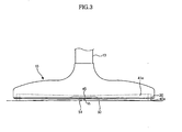
- FIGS. 3 and 4 are a front view and a side sectional view illustrating the suction unit 10 after the base plate 30, the wheels 40a and 40b, and the case 20 shown in FIG. 2 are assembled thereto, respectively.
- an arch-shaped suction space 51 is defined in the front of the lower side of the suction unit 10 when the suction unit 10 is supported on the floor 50, and gradually enlarges towards the center of the suction unit 10.
- Such a suction space 51 is also defined by the second connecting rod 41 b connecting the rear wheels 40b positioned in the rear of the lower side of the suction unit 10.
- the suction unit 10 has the arch-shaped suction space 51 gradually enlarged towards the center of the suction unit 10 when the suction unit 10 is supported on the floor 50, and this structure is devised to secure a large area of an air flow path at the center of the suction unit 10 in consideration of the fact that suction force becomes the maximum value at the center of the suction unit 10 where the suction port 31 is formed, and suctioning speed of air becomes the highest value thereat.
- the lowermost surface of the base plate 30 is coplanar with or above a lowermost portion 45 of each of the connecting rods 41 a and 41 b where each of the connecting rods 41 a and 41 b has the smallest diameter.
- FIG. 5 is a graph depicting variation in noise reduction effect according to a distance "h" (which will hereinafter referred to as a "gap h") between the floor 50 supporting the wheels 40a and 40b and the lowermost portion 45 of each of the connecting rods 41 a and 41 b where each of the connecting rods 41 a and 41 b has the smallest diameter.
- h a distance between the floor 50 supporting the wheels 40a and 40b and the lowermost portion 45 of each of the connecting rods 41 a and 41 b where each of the connecting rods 41 a and 41 b has the smallest diameter.
- the gap h is preferably in the range of 1.5 ⁇ 2 mm.
- the base plate 30 constituting the lower surface of the suction unit 10 since the base plate 30 constituting the lower surface of the suction unit 10 has a complicated structure, it is difficult to form the base plate 30 such that the gap h of about 1.8 mm is defined between the floor 50 and the lowermost portion 45 of each connecting rod.
- this gap can be secured by the structure wherein the connecting rods 41 a and 41 b are formed to have the reversed arch-shaped outer periphery gradually decreased in diameter to define the suction space 51 between the connecting rods 41 a and 41 b and the floor 50.
- the base plate 30 is likely to deform when the thin base plate 30 is fastened to the case 20 by the fastening members 35, and thus it is difficult to maintain the gap of about 1.8 mm with respect to the floor.
- the reversed arch-shaped outer periphery of the connecting rods can overcome such a difficulty.
- first and second connecting rods 41 a and 41 b are integrally formed with the front and rear wheels 40a and 40b, respectively, and have the symmetrical shape with respect to the axis thereof, so that, when the suction unit 10 is moved, and the respective wheels 40a and 40b are rotated with respect to the shafts 42a and 42b, the respective connecting rods 41 a and 41 b can maintain a constant gap h from the floor 50.
- the front wheels 40a and the first connecting rod 41a connecting the front wheels 40a with each other are disposed at the front side of the suction unit 10
- the rear wheels 40b and the second connecting rod 41 b connecting the rear wheels 40b with each other are disposed at the rear side of the suction unit 10.
- the connecting rods and wheels are not necessarily disposed at both front and rear sides of the suction unit.
- a pair of wheels and a connecting rod to connect the wheels may be disposed at one side of the front side and the rear side of the suction unit.
- the vacuum cleaner according to the present invention has a suction space formed between the floor and the connecting rod to connect the wheels of the suction unit to define an air flow path through which air is suctioned into the suction unit, so that noise generated from the suction unit is significantly reduced.
- the suction unit is provided at a lower side with the wheels, it is possible to maneuver the suction unit with a small maneuvering force.
Landscapes
- Engineering & Computer Science (AREA)
- Mechanical Engineering (AREA)
- Architecture (AREA)
- Civil Engineering (AREA)
- Structural Engineering (AREA)
- Nozzles For Electric Vacuum Cleaners (AREA)
- Electric Suction Cleaners (AREA)
Claims (5)
- Staubsauger, umfassend
einen Körper (11) zum Erzeugen einer Saugkraft,
eine Saugeinheit (10), die mit dem Körper (11) verbunden ist, um Staub aufzusaugen,
wobei die Saugeinheit (10), wenn sie auf einem Fußboden (50) steht, eine bogenförmige Saugaussparung (51) hat, die an der Vorderseite und/oder an der Rückseite der Saugeinheit (10) ausgebildet ist, wobei die Saugaussparung (51) sukzessive innerwärts zu einer zentralen Region der Saugeinheit (10) größer wird, und wobei die Saugeinheit (10) ein Gehäuse (20), das ein äußeres Erscheinungsbild definiert, eine Basisplatte (30), die eine Bodenoberfläche der Saugeinheit (10) darstellt und mit einer Saugöffnung (31) ausgebildet ist, durch welche der Staub in die Saugeinheit (10) gesaugt werden kann, sowie eine Vielzahl von Rädern (40a, 40b), die an vorderen gegenüberliegenden Seiten und/oder an hinteren gegenüberliegenden Seiten der Saugeinheit (10) befestigt sind, um der Saugeinheit (10) zu gestatten, auf dem Fußboden zu rollen, umfasst,
wobei die Räder (40a, 40b) bezüglich der Saugöffnung (31) durch eine Verbindungsstange (41 a, 41 b) verbunden sind, die einen kleineren Durchmesser als jedes der Räder (40a, 40b) hat,
dadurch gekennzeichnet, dass
die Verbindungsstange (41 a, 41 b) eine bogenförmige Umfangsfläche umfasst und sukzessive innerwärts Richtung Zentrum der Verbindungsstange (41 a, 41 b) im Durchmesser abnimmt. - Staubsauger nach Anspruch 1, wobei die Verbindungsstange (41 a, 41 b) integral mit den Rädern (40a, 40b) ausgebildet ist.
- Staubsauger nach Anspruch 1 oder 2, wobei die Verbindungsstange (41a, 41b) eine symmetrische Form bezüglich einer Achse der Verbindungsstange (41 a, 41 b) aufweist, sodass die Verbindungsstange (41 a, 41 b) in gleichbleibendem Abstand vom Fußboden (50), der die Räder (40a, 40b) unterstützt, gehalten werden kann, wenn die Räder (40a, 40b) auf dem Fußboden (50) rollen.
- Staubsauger nach einem der Ansprüche 1 bis 3, wobei ein tiefster Bereich (45) der Verbindungsstange (41 a, 41 b), wo die Verbindungsstange (41 a, 41 b) den kleinsten Durchmesser hat, eine Entfernung von 1.5 bis 2.2 mm vom Fußboden (50), der die Räder (40a, 40b) unterstützt, entfernt ist.
- Staubsauger nach einem der Ansprüche 1 bis 4, wobei die Basisplatte 30 eine unterste Oberfläche (30a, 30b) hat, die in der gleichen Ebene des unteren Bereichs (45) der Verbindungsstange (41a, 41 b), wo die Verbindungsstange (41 a, 41 b) den kleinsten Durchmesser hat, oder darüber liegt.
Applications Claiming Priority (1)
| Application Number | Priority Date | Filing Date | Title |
|---|---|---|---|
| KR1020060004025A KR101211497B1 (ko) | 2006-01-13 | 2006-01-13 | 진공청소기 |
Publications (3)
| Publication Number | Publication Date |
|---|---|
| EP1808113A2 EP1808113A2 (de) | 2007-07-18 |
| EP1808113A3 EP1808113A3 (de) | 2009-08-19 |
| EP1808113B1 true EP1808113B1 (de) | 2014-09-24 |
Family
ID=37908217
Family Applications (1)
| Application Number | Title | Priority Date | Filing Date |
|---|---|---|---|
| EP06008559.4A Ceased EP1808113B1 (de) | 2006-01-13 | 2006-04-25 | Staubsauger |
Country Status (3)
| Country | Link |
|---|---|
| EP (1) | EP1808113B1 (de) |
| KR (1) | KR101211497B1 (de) |
| RU (1) | RU2319435C1 (de) |
Families Citing this family (5)
| Publication number | Priority date | Publication date | Assignee | Title |
|---|---|---|---|---|
| KR20160026269A (ko) * | 2014-08-29 | 2016-03-09 | 삼성전자주식회사 | 흡입노즐 및 이를 구비한 진공청소기 |
| DE102015104436A1 (de) * | 2015-03-24 | 2016-09-29 | Wessel-Werk Gmbh | Gleitsohle für eine Staubsaugerdüse |
| DE102015108051B4 (de) * | 2015-05-21 | 2019-08-22 | Vorwerk & Co. Interholding Gmbh | Hartbodendüse für Grobgut und Feinstaubaufnahme |
| DE102015108052B4 (de) * | 2015-05-21 | 2020-02-13 | Vorwerk & Co. Interholding Gmbh | Saugdüse zur Aufnahme von Grobgut und Feinstaub |
| DE102015108050A1 (de) * | 2015-05-21 | 2016-11-24 | Vorwerk & Co. Interholding Gmbh | Saugdüse zur Aufnahme von Grobgut und Feinstaub |
Family Cites Families (11)
| Publication number | Priority date | Publication date | Assignee | Title |
|---|---|---|---|---|
| US1560400A (en) * | 1921-02-24 | 1925-11-03 | Wise Mcclung Company Ltd | Suction cleaner |
| US1654186A (en) * | 1921-06-06 | 1927-12-27 | Hoover Co | Suction sweeper |
| US2597808A (en) * | 1947-04-25 | 1952-05-20 | Hoover Co | Suction cleaner nozzle with rocking lever type adjustable brush |
| US2620506A (en) * | 1947-04-25 | 1952-12-09 | Hoover Co | Suction cleaning tool with adjustable brush |
| US2629126A (en) * | 1948-10-12 | 1953-02-24 | Electrolux Corp | Suction nozzle with adjustable cleaning opening |
| FR1422936A (fr) * | 1964-11-03 | 1966-01-03 | Olivier Ets Georges | Perfectionnements aux suceurs d'aspirateurs |
| SE405200B (sv) * | 1977-04-29 | 1978-11-27 | Electrolux Ab | Valsborste for dammsugare |
| US4219902A (en) * | 1979-02-09 | 1980-09-02 | Oreck Corporation | Vacuum cleaning |
| SU1489716A2 (ru) * | 1987-11-06 | 1989-06-30 | Belgorodskij Ti Str Material | Hacaдok для oчиctkи плockиx пobepxhocteй |
| FR2856267B1 (fr) * | 2003-06-20 | 2005-07-22 | Seb Sa | Suceur d'aspirateur |
| KR100582519B1 (ko) * | 2004-07-09 | 2006-05-23 | 삼성광주전자 주식회사 | 진공청소기의 흡입브러시 |
-
2006
- 2006-01-13 KR KR1020060004025A patent/KR101211497B1/ko not_active Expired - Fee Related
- 2006-04-25 EP EP06008559.4A patent/EP1808113B1/de not_active Ceased
- 2006-05-11 RU RU2006116255/12A patent/RU2319435C1/ru not_active IP Right Cessation
Also Published As
| Publication number | Publication date |
|---|---|
| EP1808113A2 (de) | 2007-07-18 |
| EP1808113A3 (de) | 2009-08-19 |
| RU2319435C1 (ru) | 2008-03-20 |
| KR101211497B1 (ko) | 2012-12-12 |
| KR20070075598A (ko) | 2007-07-24 |
Similar Documents
| Publication | Publication Date | Title |
|---|---|---|
| CN1668238B (zh) | 具有边缘抽吸管的真空吸尘器吸嘴组件 | |
| KR101315876B1 (ko) | 표면 처리 헤드 | |
| US10646083B2 (en) | Vacuum cleaner with angled wheels | |
| CN100534373C (zh) | 用于清洁用具的清洁头 | |
| CA2658369A1 (en) | Surface cleaning head | |
| AU2003207685A1 (en) | Vacuum cleaner nozzle assembly having edge-cleaning ducts | |
| JP2010512894A (ja) | 表面処理用電気器具のための床用ツール | |
| WO2004105567A1 (en) | A cleaning appliance | |
| EP2398368B1 (de) | Staubsaugerdüse | |
| EP2103242B1 (de) | Bürstenanordnung und Staubsauger damit | |
| US20260114694A1 (en) | Suction port structure of cleaning machine and cleaning machine thereof | |
| EP1808113A2 (de) | Staubsauger | |
| US7594297B2 (en) | Angle control apparatus for upright type vacuum cleaner | |
| US20070067946A1 (en) | Suction brush of vacuum cleaner | |
| EP4289321B1 (de) | Saugdüse für extraktionsreiniger | |
| CN210541331U (zh) | 一种吸尘口高度快速调节的吸尘器地刷 | |
| CN219720569U (zh) | 清洁设备及清洁头 | |
| CN215016746U (zh) | 吸尘器用地刷及吸尘器 | |
| EP4536051B1 (de) | Staubsaugerdüse und staubsauger | |
| CN223715647U (zh) | 一种手持平推式除螨清洁设备 | |
| JP4215529B2 (ja) | 吸込口体及びこれを備えた電気掃除機 | |
| CN113069038A (zh) | 吸尘器用地刷及吸尘器 | |
| KR200242788Y1 (ko) | 진공청소기의 흡입구 | |
| KR200144888Y1 (ko) | 진공청소기의흡입체 | |
| KR200344833Y1 (ko) | 닦는 기능이 구비된 진공 청소기 |
Legal Events
| Date | Code | Title | Description |
|---|---|---|---|
| PUAI | Public reference made under article 153(3) epc to a published international application that has entered the european phase |
Free format text: ORIGINAL CODE: 0009012 |
|
| AK | Designated contracting states |
Kind code of ref document: A2 Designated state(s): AT BE BG CH CY CZ DE DK EE ES FI FR GB GR HU IE IS IT LI LT LU LV MC NL PL PT RO SE SI SK TR |
|
| AX | Request for extension of the european patent |
Extension state: AL BA HR MK YU |
|
| PUAL | Search report despatched |
Free format text: ORIGINAL CODE: 0009013 |
|
| AK | Designated contracting states |
Kind code of ref document: A3 Designated state(s): AT BE BG CH CY CZ DE DK EE ES FI FR GB GR HU IE IS IT LI LT LU LV MC NL PL PT RO SE SI SK TR |
|
| AX | Request for extension of the european patent |
Extension state: AL BA HR MK YU |
|
| RIC1 | Information provided on ipc code assigned before grant |
Ipc: A47L 9/02 20060101AFI20070425BHEP Ipc: A47L 9/00 20060101ALI20090714BHEP |
|
| 17P | Request for examination filed |
Effective date: 20100115 |
|
| 17Q | First examination report despatched |
Effective date: 20100210 |
|
| AKX | Designation fees paid |
Designated state(s): DE FR GB |
|
| RAP1 | Party data changed (applicant data changed or rights of an application transferred) |
Owner name: SAMSUNG ELECTRONICS CO., LTD. |
|
| GRAP | Despatch of communication of intention to grant a patent |
Free format text: ORIGINAL CODE: EPIDOSNIGR1 |
|
| INTG | Intention to grant announced |
Effective date: 20140410 |
|
| GRAS | Grant fee paid |
Free format text: ORIGINAL CODE: EPIDOSNIGR3 |
|
| GRAA | (expected) grant |
Free format text: ORIGINAL CODE: 0009210 |
|
| AK | Designated contracting states |
Kind code of ref document: B1 Designated state(s): DE FR GB |
|
| REG | Reference to a national code |
Ref country code: GB Ref legal event code: FG4D |
|
| REG | Reference to a national code |
Ref country code: DE Ref legal event code: R096 Ref document number: 602006043116 Country of ref document: DE Effective date: 20141030 |
|
| REG | Reference to a national code |
Ref country code: DE Ref legal event code: R097 Ref document number: 602006043116 Country of ref document: DE |
|
| PLBE | No opposition filed within time limit |
Free format text: ORIGINAL CODE: 0009261 |
|
| STAA | Information on the status of an ep patent application or granted ep patent |
Free format text: STATUS: NO OPPOSITION FILED WITHIN TIME LIMIT |
|
| 26N | No opposition filed |
Effective date: 20150625 |
|
| REG | Reference to a national code |
Ref country code: FR Ref legal event code: PLFP Year of fee payment: 11 |
|
| REG | Reference to a national code |
Ref country code: FR Ref legal event code: PLFP Year of fee payment: 12 |
|
| REG | Reference to a national code |
Ref country code: FR Ref legal event code: PLFP Year of fee payment: 13 |
|
| PGFP | Annual fee paid to national office [announced via postgrant information from national office to epo] |
Ref country code: GB Payment date: 20180321 Year of fee payment: 13 |
|
| PGFP | Annual fee paid to national office [announced via postgrant information from national office to epo] |
Ref country code: FR Payment date: 20180322 Year of fee payment: 13 |
|
| PGFP | Annual fee paid to national office [announced via postgrant information from national office to epo] |
Ref country code: DE Payment date: 20180320 Year of fee payment: 13 |
|
| REG | Reference to a national code |
Ref country code: DE Ref legal event code: R119 Ref document number: 602006043116 Country of ref document: DE |
|
| GBPC | Gb: european patent ceased through non-payment of renewal fee |
Effective date: 20190425 |
|
| PG25 | Lapsed in a contracting state [announced via postgrant information from national office to epo] |
Ref country code: GB Free format text: LAPSE BECAUSE OF NON-PAYMENT OF DUE FEES Effective date: 20190425 Ref country code: DE Free format text: LAPSE BECAUSE OF NON-PAYMENT OF DUE FEES Effective date: 20191101 |
|
| PG25 | Lapsed in a contracting state [announced via postgrant information from national office to epo] |
Ref country code: FR Free format text: LAPSE BECAUSE OF NON-PAYMENT OF DUE FEES Effective date: 20190430 |