EP1808112A2 - Steuervorrichtung von drehbarer Bürste für einen Staubsauger - Google Patents
Steuervorrichtung von drehbarer Bürste für einen Staubsauger Download PDFInfo
- Publication number
- EP1808112A2 EP1808112A2 EP06016337A EP06016337A EP1808112A2 EP 1808112 A2 EP1808112 A2 EP 1808112A2 EP 06016337 A EP06016337 A EP 06016337A EP 06016337 A EP06016337 A EP 06016337A EP 1808112 A2 EP1808112 A2 EP 1808112A2
- Authority
- EP
- European Patent Office
- Prior art keywords
- moving member
- rotating brush
- guiding
- control apparatus
- disposed
- Prior art date
- Legal status (The legal status is an assumption and is not a legal conclusion. Google has not performed a legal analysis and makes no representation as to the accuracy of the status listed.)
- Granted
Links
Images



Classifications
-
- A—HUMAN NECESSITIES
- A47—FURNITURE; DOMESTIC ARTICLES OR APPLIANCES; COFFEE MILLS; SPICE MILLS; SUCTION CLEANERS IN GENERAL
- A47L—DOMESTIC WASHING OR CLEANING; SUCTION CLEANERS IN GENERAL
- A47L5/00—Structural features of suction cleaners
- A47L5/12—Structural features of suction cleaners with power-driven air-pumps or air-compressors, e.g. driven by motor vehicle engine vacuum
- A47L5/22—Structural features of suction cleaners with power-driven air-pumps or air-compressors, e.g. driven by motor vehicle engine vacuum with rotary fans
- A47L5/28—Suction cleaners with handles and nozzles fixed on the casings, e.g. wheeled suction cleaners with steering handle
- A47L5/30—Suction cleaners with handles and nozzles fixed on the casings, e.g. wheeled suction cleaners with steering handle with driven dust-loosening tools, e.g. rotating brushes
-
- E—FIXED CONSTRUCTIONS
- E05—LOCKS; KEYS; WINDOW OR DOOR FITTINGS; SAFES
- E05C—BOLTS OR FASTENING DEVICES FOR WINGS, SPECIALLY FOR DOORS OR WINDOWS
- E05C7/00—Fastening devices specially adapted for two wings
- E05C7/02—Fastening devices specially adapted for two wings for wings which lie one behind the other when closed
-
- A—HUMAN NECESSITIES
- A47—FURNITURE; DOMESTIC ARTICLES OR APPLIANCES; COFFEE MILLS; SPICE MILLS; SUCTION CLEANERS IN GENERAL
- A47L—DOMESTIC WASHING OR CLEANING; SUCTION CLEANERS IN GENERAL
- A47L9/00—Details or accessories of suction cleaners, e.g. mechanical means for controlling the suction or for effecting pulsating action; Storing devices specially adapted to suction cleaners or parts thereof; Carrying-vehicles specially adapted for suction cleaners
- A47L9/02—Nozzles
- A47L9/04—Nozzles with driven brushes or agitators
-
- E—FIXED CONSTRUCTIONS
- E05—LOCKS; KEYS; WINDOW OR DOOR FITTINGS; SAFES
- E05B—LOCKS; ACCESSORIES THEREFOR; HANDCUFFS
- E05B1/00—Knobs or handles for wings; Knobs, handles, or press buttons for locks or latches on wings
- E05B1/003—Handles pivoted about an axis perpendicular to the wing
-
- E—FIXED CONSTRUCTIONS
- E05—LOCKS; KEYS; WINDOW OR DOOR FITTINGS; SAFES
- E05C—BOLTS OR FASTENING DEVICES FOR WINGS, SPECIALLY FOR DOORS OR WINDOWS
- E05C9/00—Arrangements of simultaneously actuated bolts or other securing devices at well-separated positions on the same wing
- E05C9/02—Arrangements of simultaneously actuated bolts or other securing devices at well-separated positions on the same wing with one sliding bar for fastening when moved in one direction and unfastening when moved in opposite direction; with two sliding bars moved in the same direction when fastening or unfastening
- E05C9/025—Arrangements of simultaneously actuated bolts or other securing devices at well-separated positions on the same wing with one sliding bar for fastening when moved in one direction and unfastening when moved in opposite direction; with two sliding bars moved in the same direction when fastening or unfastening with pins engaging slots
-
- E—FIXED CONSTRUCTIONS
- E05—LOCKS; KEYS; WINDOW OR DOOR FITTINGS; SAFES
- E05Y—INDEXING SCHEME ASSOCIATED WITH SUBCLASSES E05D AND E05F, RELATING TO CONSTRUCTION ELEMENTS, ELECTRIC CONTROL, POWER SUPPLY, POWER SIGNAL OR TRANSMISSION, USER INTERFACES, MOUNTING OR COUPLING, DETAILS, ACCESSORIES, AUXILIARY OPERATIONS NOT OTHERWISE PROVIDED FOR, APPLICATION THEREOF
- E05Y2900/00—Application of doors, windows, wings or fittings thereof
- E05Y2900/10—Application of doors, windows, wings or fittings thereof for buildings or parts thereof
- E05Y2900/13—Type of wing
- E05Y2900/148—Windows
Definitions
- the present disclosure relates to a vacuum cleaner. More particularly, the present disclosure relates to a rotating brush driving control apparatus for a vacuum cleaner to control driving of a rotating brush for cleaning a surface to be cleaned.
- a vacuum cleaner has a suction motor, and draws in contaminants using suction force generated by the suction motor so as to clean a surface to be cleaned.
- vacuum cleaners are being marketed that have a substantially drum-shape rotating brush with bristles fixed in a helical shape on an outer circumferential surface thereof. Therefore, the vacuum cleaners can remove contaminants from a surface to be cleaned which is difficult to clean by simply drawing-in contaminants.
- the rotating brush is not always required for cleaning work.
- vacuum cleaners have been developed that can selectively control driving of the rotating brush according to the state of a surface to be cleaned or a cleaning environment.
- An example of this type of vacuum cleaner is disclosed in U.S. Patent No. 6,158,084 .
- the vacuum cleaner controls driving of the rotating brush by adjusting the tension of a driving belt.
- the conventional rotating brush driving control apparatus has a very complex structure so that it is not easy to maintain the vacuum cleaner.
- there is another problem with the complex structure in that the manufacturing cost of the vacuum cleaner is increased. Therefore, there is a continuing need for vacuum cleaners that overcome one or more of the aforementioned and other problems of the prior vacuum cleaners.
- An aspect of the present disclosure is to provide a rotating brush driving control apparatus for a vacuum cleaner capable of easily controlling driving of a rotating brush with a simple structure.
- a rotating brush driving control apparatus for a vacuum cleaner that applies the tension force to a driving belt connecting a motor disposed in a cleaner body and a rotating brush disposed in a suction brush assembly so as to control driving of the rotating brush.
- the rotating brush driving control apparatus includes: a supporting bracket disposed in the suction brush assembly; a moving member slidably and elastically disposed in the supporting bracket; a lever disposed above the driving belt, the lever having an end rotatably disposed at a side of the supporting bracket; a tension spring elastically connecting the moving member and the lever, and a locking member disposed below the moving member, the locking member locking or unlocking the moving member in turn according as the moving member is downwardly pressed; wherein, when the locking member locks the moving member, the other end of the lever presses the driving belt by the tension spring so that the driving belt transmits the driving power to the rotating brush, and wherein, when the locking member unlocks the moving member, the tension spring releases the other end of the lever from the driving belt.
- the moving member includes a sliding part slidably disposed in the supporting bracket; a vertical bar extended from an upper side of the sliding part through the suction brush assembly; and a pedal formed at a top end of the vertical bar. Therefore, users simply step the pedal protruded outside the suction brush assembly to transmit the driving power to the rotating brush or to prevent the driving power from being transmitted to the rotating brush.
- the tension spring determines the tension force applied to the driving belt. Therefore, when the driving belt becomes longer due to a long usage, another tension spring with different strength can be used to apply a predetermined tension force to the driving belt.
- the lever may include a pulley rotatably disposed at the other end of the lever so as to be in rotating contact with the driving belt, wherein, when the lever presses the driving belt, the friction force between the lever and the driving belt is minimized.
- the locking member includes: a return spring disposed inside the supporting bracket so as to elastically support a bottom end of the moving member; a guiding portion formed inside the sliding part; and a torsion spring having an end fixed at a bottom surface of the supporting bracket and the other end corresponding to the guiding portion, wherein, when the moving member is pressed, the torsion spring is moved along the guiding portion so as to lock and unlock the moving member.
- the guiding portion may include a first guiding projection having an upwardly guiding surface guiding the other end of the torsion spring in an upwardly inclined direction, a downwardly guiding surface guiding the other end of the torsion spring in a downwardly inclined direction, and a hooking groove formed at an upper side of the first guiding projection to receive the other end of the torsion spring; and a second guiding projection nearly formed above the hooking groove of the first guiding projection so as to help the other end of the torsion spring to be received in and to be released from the hooking groove.
- the guiding portion further comprises at least one third guiding projection continuously guiding the other end of the torsion spring moving along the downwardly guiding surface to return to an original position.
- Fig. 1 is a perspective view illustrating a vacuum cleaner employing a rotating brush driving control apparatus according to an embodiment of the present disclosure
- Fig. 2 is a bottom view illustrating the vacuum cleaner of Fig. 1;
- Fig. 3 is a perspective view illustrating a rotating brush driving control apparatus according to an embodiment of the present disclosure disposed in a suction brush assembly of the vacuum cleaner of Fig. 1;
- Fig. 4 is an exploded perspective view illustrating the rotating brush driving control apparatus of Fig. 3;
- Fig. 5 is a sectional schematic view illustrating a torsion spring disposed in a supporting bracket of Fig. 4;
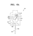
- Fig. 6a is a schematic view illustrating a locking member before operation of a rotating brush driving control apparatus according to an embodiment of the present disclosure
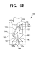
- Fig. 6b is a schematic view illustrating the locking member after operation of the rotating brush driving control apparatus
- Fig. 7a is a schematic view illustrating a driving belt before operation of a rotating brush driving control apparatus according to an embodiment of the present disclosure
- Fig. 7b is a schematic view illustrating the driving belt after operation of the rotating brush driving control apparatus.
- Fig. 1 is a perspective view illustrating a vacuum cleaner employing a rotating brush driving control apparatus according to an embodiment of the present disclosure
- Fig. 2 is a bottom view illustrating the vacuum cleaner of Fig. 1
- Fig. 3 is a perspective view illustrating a rotating brush driving control apparatus according to an embodiment of the present disclosure disposed in a suction brush assembly of the vacuum cleaner of Fig. 1
- Fig. 4 is an exploded perspective view illustrating the rotating brush driving control apparatus of Fig. 3
- Fig. 5 is a sectional schematic view illustrating a torsion spring disposed in a supporting bracket of Fig. 4.
- an upright type vacuum cleaner 10 is used as an example of vacuum cleaners employing a rotating brush driving control apparatus according to an embodiment of the present disclosure as shown in Fig. 1; however, this should not be considered as limiting.
- Various types of vacuum cleaners such as upright type vacuum cleaners, handy type vacuum cleaners, vacuum cleaners wherein a suction brush assembly is connected with a cleaner body via a flexible hose, and so on may employ a rotating brush driving control apparatus according to an embodiment of the present disclosure.
- a vacuum cleaner 10 includes a cleaner body 11 having a handle 13 on an upper side thereof, and a suction brush assembly 15 pivotally disposed at an under side of the cleaner body 11. Also, the vacuum cleaner 10 further includes a pair of wheels 17 disposed at opposite sides of the suction brush assembly 15 so as to smoothly move on a surface to be cleaned.
- the suction brush assembly 15 has a rotating brush 40 rotatably disposed at a bottom surface of the suction brush assembly 15 as shown in Fig. 2.
- the rotating brush 40 is connected with a driving shaft 21 of a motor 20 (see Fig. 7a) via a driving belt 30.
- a rotating brush driving control apparatus 100 shown in Figs. 3 and 4, is disposed inside the suction brush assembly 15 to selectively apply the tension force on the driving belt 30 so that the driving power of the motor 20 is selectively transmitted to the rotating brush 40. Also, the rotating brush driving control apparatus 100 is arranged nearby the driving belt 30 between the motor 20 and the rotating brush 40 as shown in Fig. 7a.
- the rotating brush driving control apparatus 100 includes a supporting bracket 110, a moving member 120, a locking member 130, a lever 140, and a tension spring 150.
- the supporting bracket 110 is disposed inside the suction brush assembly 15, and has a first receiving space 111 into which an lower portion of the moving member 120 is slidably inserted in a vertical direction.
- the supporting bracket 110 has a second receiving space 113 in fluid communication with the first receiving space 111.
- the tension spring 150 is inserted into the second receiving space 113 and the opposite ends of which are engaged with a first fixing protrusion 151 fixed at the sliding part 125 of the moving member 120 and a second fixing protrusion 153 fixed at the lever 140.
- an extension part 117 is formed at a side of the second receiving space 113 so as to support an end of the lever 140.
- a pair of connecting holes 119 with which a pair of pivot projections 145 of the lever 140 is connected.
- the other end of the lever 140 comprises a holding part 141 in which a pulley 149 is rotatably disposed by means of a shaft 146 and bearings 147.
- the shaft 146 is fixed at inside opposite ends of the holding part 141.
- the moving member 120 includes a sliding part 125 slidably disposed at the supporting bracket 110 and a vertical bar 123 extending from an upper side of the sliding part 125 through an top surface of the suction brush assembly 15 as shown in Fig. 1, and a pedal 121 disposed on a top end of the vertical bar 123.
- the pedal 121 has a predetermined area so that users can press the moving member 120.
- a guiding portion 131 is formed inside the sliding part 125 so that the guiding portion 131 guides an end, namely a hooking part 136d, of a torsion spring 136 according as the moving member 120 rises or lowers as described below.
- the locking member 130 is disposed below the moving member 120 so as to lock or unlock the moving member 120 in turn according as the moving member 120 is downwardly pressed.
- the locking member 130 includes the guiding portion 131, the torsion spring 136, and a return spring 137.
- the guiding portion 131 has a first, second, and third guiding projections 132, 133, and 134 therein as shown in Figs. 6a and 6b.
- the first guiding projection 132 has an upwardly guiding surface 132a guiding the hooking part 136d of the torsion spring 136 in an upwardly inclined direction, a downwardly guiding surface 132c guiding the hooking part 136d of the torsion spring 136 in a downwardly inclined direction, and a hooking groove 132b formed on an upper side of the first guiding projection 132 in a substantially arc shape so as to receive the hooking part 136d.
- a center C of the hooking groove 132b is spaced apart from a vertical part 136c of the torsion spring 136 in a lateral direction as shown in Fig. 6a.
- the second guiding projection 133 is nearly formed above the hooking groove 132b of the first guiding projection 132 so that it helps the hooking part 136d to be received in and to be left from the hooking groove 132b.
- the third guiding projection 134 is formed below the first guiding projection 132 so that it continuously guides the hooking part 136d of the torsion spring 136 moving along the downwardly guiding surface 132c to return to an original position. Furthermore, the third guiding projection 134 may comprise a pair of third guiding projections facing each other as shown in Fig. 6a so as to guide the hooking part 136d inside and outside the guiding portion 131.
- the torsion spring 136 is formed in a line shape, and includes a fixing part 136a, a horizontal part 136b, a vertical part 136c, and a hooking part 136d as shown in Fig. 5. That is, an end of the torsion spring 136 is the fixing part 136a, and the other end of the torsion spring 136 is the hooking part 136d.
- the fixing part 136a is inserted and fixed into a fixing hole 111a formed at a bottom surface of the first receiving space 111 of the supporting bracket 110.
- the horizontal part 136b is bent and extended along the bottom surface of the first receiving space 111 from a rear end of the fixing part 136a so that a pair of fixing bits 111b and 111c supports opposite sides of the horizontal part 136b.
- the vertical part 136c is bent and extended from a rear end of the horizontal part 136b so as to be inserted by a predetermined length into the first receiving space 111 through a piercing hole 111d formed at the bottom surface of the first receiving space 111.
- the hooking part 136d is bent from a rear end of the vertical part 136c so as to be guided by the guiding portion 131 (see Fig. 4) formed inside the sliding part 125. At this time, when the hooking part 136d is guided in the upwardly or downwardly inclined direction according to a lowering or rising of the moving member 120, the horizontal part 136b receives the torsional force as much as the force rotating the hooking part 136d by a predetermined angle.
- the above-described structure and torsional force of the torsion spring 136 causes the moving member 120 to be locked or to be unlocked.
- the return spring 137 is disposed between a bottom end of the sliding part 125 and the bottom surface of the first receiving space 111 of the supporting bracket 110 so as to elastically support the moving member 120.
- a bottom end of the return spring 137 is fixed at a supporting projection 111 e protruded from the bottom surface of the first receiving space 111.
- Fig. 6a is a schematic view illustrating the locking member before the rotating brush driving control apparatus operates
- Fig. 6b is a schematic view illustrating the locking member after operation of the rotating brush driving control apparatus
- Fig. 7a is a schematic view illustrating the driving belt before the rotating brush driving control apparatus operates
- Fig. 7b is a schematic view illustrating the driving belt after the rotating brush driving control apparatus operates.
- the driving belt 30 loosely connects the driving shaft 21 and the rotating brush 40 with no tension force so that the driving power of the driving shaft 21 is not transmitted to the rotating brush 40.
- the hooking part 136d moves along and presses the upwardly guiding surface 132a by the twist of the horizontal part 136b so that the hooking part 136d is elastically moved to the second guiding projection 133 at an end point of the upwardly guiding surface 132a by the torsional force of the horizontal part 136b. At this time, the hooking part 136d is stopped by a plain surface 133a of the second guiding projection 133.
- the moving member 120 When the user releases the pedal 121, the moving member 120 is elastically lifted at a predetermined distance by the return spring 137, and simultaneously, the hooking part 136d is received in the hooking groove 132b so that the moving member 120 is locked in a lowering position. In other words, the moving member 120 is maintained in a locking state.
- the vertical part 136c of the torsion spring 136 is slightly rotated to a side as shown in Fig. 6b so that some torsional force is applied to the horizontal part 136b of the torsion spring 136. Therefore, when the moving member 120 is unlocked as described below, the hooking part 136d can be easily removed from the hooking groove 132b.
- the first and second guiding projections 132 and 133 are lowered with the moving member 120 so that the hooking part 136d is released from the hooking groove 132b and elastically moved along a round surface 133b of the second guiding projection 133.
- the moving member 120 is elastically moved in an upward direction by the return spring 137, and simultaneously, the hooking part 136d is moved along the downwardly guiding surface 132c of the first guiding projection 132 by the torsional force of the horizontal part 136b.
- the horizontal part 136b has again the torsional force according as the vertical part 136c is rotated in the left direction.
- the hooking part 136d is moved along the downwardly guiding surface 136c, and then, is continuously guided by anyone of the pair of third guiding projections 134. Therefore, the moving member 120 is returned to the initial position as shown in Fig. 7a, and the torsion spring 136 is also returned to an original position.
- the rotating brush driving control apparatus for a vacuum cleaner has a simple structure so as to provide an easy maintenance and repair. Because of the simple structure, a light suction brush assembly can be provided and manufacturing cost thereof is decreased.
- the rotating brush driving control apparatus provides accurate locking and unlocking of the moving member so that reliability of the vacuum cleaner is increased.
Landscapes
- Engineering & Computer Science (AREA)
- Mechanical Engineering (AREA)
- Nozzles For Electric Vacuum Cleaners (AREA)
Applications Claiming Priority (1)
| Application Number | Priority Date | Filing Date | Title |
|---|---|---|---|
| KR1020060004819A KR100681495B1 (ko) | 2006-01-17 | 2006-01-17 | 진공청소기의 회전브러시 구동제어장치 |
Publications (3)
| Publication Number | Publication Date |
|---|---|
| EP1808112A2 true EP1808112A2 (de) | 2007-07-18 |
| EP1808112A3 EP1808112A3 (de) | 2008-10-08 |
| EP1808112B1 EP1808112B1 (de) | 2010-05-19 |
Family
ID=37564408
Family Applications (1)
| Application Number | Title | Priority Date | Filing Date |
|---|---|---|---|
| EP06016337A Ceased EP1808112B1 (de) | 2006-01-17 | 2006-08-04 | Drehbürsten-Steuervorrichtung für einen Staubsauger |
Country Status (5)
| Country | Link |
|---|---|
| US (1) | US7426770B2 (de) |
| EP (1) | EP1808112B1 (de) |
| KR (1) | KR100681495B1 (de) |
| CN (1) | CN101002668A (de) |
| AU (1) | AU2006203370B2 (de) |
Families Citing this family (13)
| Publication number | Priority date | Publication date | Assignee | Title |
|---|---|---|---|---|
| US7937804B2 (en) * | 2008-04-08 | 2011-05-10 | Royal Appliance Mfg. Co. | Belt lifter mechanism for vacuum cleaner |
| GB2468908B (en) * | 2009-03-27 | 2012-06-20 | Dyson Technology Ltd | Clutch assembly |
| GB2468909B (en) * | 2009-03-27 | 2012-06-20 | Dyson Technology Ltd | Clutch assembly |
| US8336162B2 (en) * | 2009-10-06 | 2012-12-25 | Panasonic Corporation Of North America | Agitator belt drive interrupt system |
| US8756757B2 (en) | 2011-09-07 | 2014-06-24 | Bissell Homecare, Inc. | Vacuum cleaner with belt drive disengager |
| TW201338741A (zh) * | 2012-03-22 | 2013-10-01 | Ememe Robot Co Ltd | 清潔機器人及控制清潔機器人側刷之方法 |
| CN103767627B (zh) * | 2012-10-19 | 2016-08-31 | 莱克电气股份有限公司 | 智能吸尘器及其滚刷组件 |
| CN110367872A (zh) * | 2015-08-28 | 2019-10-25 | 科沃斯机器人股份有限公司 | 地刷及其吸尘器 |
| CN105411484B (zh) * | 2015-12-10 | 2017-09-22 | 江苏美的清洁电器股份有限公司 | 立式吸尘器的离合装置和具有其的立式吸尘器 |
| CN105476548B (zh) * | 2016-01-04 | 2019-02-15 | 江苏美的清洁电器股份有限公司 | 吸尘器的皮带离合器组件和具有其的吸尘器 |
| CN105942937B (zh) * | 2016-07-07 | 2018-11-06 | 大连交通大学 | 一种压力自适应的双拖板拖地装置 |
| KR102035138B1 (ko) * | 2018-02-20 | 2019-10-22 | 엘지전자 주식회사 | 청소기 |
| CN116528738A (zh) | 2021-04-09 | 2023-08-01 | 三星电子株式会社 | 清洁设备 |
Family Cites Families (10)
| Publication number | Priority date | Publication date | Assignee | Title |
|---|---|---|---|---|
| US2601698A (en) * | 1949-05-17 | 1952-07-01 | Hoover Co | Suction cleaner with agitator disconnect |
| US4748714A (en) * | 1986-11-06 | 1988-06-07 | The Hoover Company | Cleaner with belt shifting |
| DE4105012C2 (de) * | 1991-02-19 | 1994-09-29 | Fedag Romanshorn Fa | Staubsaugermundstück |
| KR940000078A (ko) * | 1992-06-11 | 1994-01-03 | 이헌조 | 진공 청소기의 걸레가 장착된 흡입구 |
| US5537712A (en) * | 1995-03-20 | 1996-07-23 | The Hoover Company | Vacuum cleaner belt drive release |
| CN1127321C (zh) * | 1997-06-11 | 2003-11-12 | 松下电器产业株式会社 | 吸尘器 |
| KR19990039612U (ko) | 1998-04-15 | 1999-11-15 | 구자홍 | 진공청소기의 브러시 회전제어장치 |
| US6131238A (en) | 1998-05-08 | 2000-10-17 | The Hoover Company | Self-propelled upright vacuum cleaner with offset agitator and motor pivot points |
| CA2442830C (en) * | 2001-04-06 | 2009-09-08 | Matsushita Electric Corporation Of America | Agitator drive system for vacuum cleaner |
| KR20050094059A (ko) * | 2004-03-17 | 2005-09-27 | 엘지전자 주식회사 | 진공청소기의 흡입노즐 |
-
2006
- 2006-01-17 KR KR1020060004819A patent/KR100681495B1/ko not_active Expired - Fee Related
- 2006-07-20 US US11/490,387 patent/US7426770B2/en not_active Expired - Fee Related
- 2006-08-04 EP EP06016337A patent/EP1808112B1/de not_active Ceased
- 2006-08-08 AU AU2006203370A patent/AU2006203370B2/en not_active Ceased
- 2006-08-21 CN CNA2006101159487A patent/CN101002668A/zh active Pending
Also Published As
| Publication number | Publication date |
|---|---|
| KR100681495B1 (ko) | 2007-02-12 |
| US20070163074A1 (en) | 2007-07-19 |
| AU2006203370A1 (en) | 2007-08-02 |
| US7426770B2 (en) | 2008-09-23 |
| AU2006203370B2 (en) | 2008-05-01 |
| EP1808112B1 (de) | 2010-05-19 |
| CN101002668A (zh) | 2007-07-25 |
| EP1808112A3 (de) | 2008-10-08 |
Similar Documents
| Publication | Publication Date | Title |
|---|---|---|
| EP1808112A2 (de) | Steuervorrichtung von drehbarer Bürste für einen Staubsauger | |
| RU2221474C2 (ru) | Удлинительная труба для пылесоса (варианты) | |
| US20090144928A1 (en) | Vacuum cleaner | |
| US5991972A (en) | Height adjustment mechanism for a cleaning tool | |
| US6098243A (en) | Device for driving/stopping brush of vacuum cleaner | |
| WO2009048220A1 (en) | Seat moving track assembly | |
| US8632442B2 (en) | Weight control apparatus for a weight training machine | |
| CN1327804C (zh) | 延伸管支撑装置和具有该延伸管支撑装置的真空吸尘器 | |
| JPH08299237A (ja) | 電気掃除機 | |
| CN1153546C (zh) | 可行驶的扫路机 | |
| CN111873859B (zh) | 用于车辆座椅的滑动装置 | |
| US20250049281A1 (en) | Cleaner | |
| US9232878B2 (en) | Upright type vacuum cleaner | |
| CA2708621C (en) | Mop with wringing device | |
| CN217524979U (zh) | 地刷装置及清洁设备 | |
| US20090145993A1 (en) | Rotating apparatus for winding reel of high-pressure cleaner | |
| CN214362311U (zh) | 一种连接锁止装置和洗衣机 | |
| JP2003120622A (ja) | 伸縮自在バーおよびこの伸縮自在バーを備えた柄付き用具 | |
| CN215656965U (zh) | 折叠手柄及清洗机 | |
| CN222737805U (zh) | 连接轴、转轴开关机构及洗地机 | |
| CN211229815U (zh) | 推拉式房间门锁 | |
| CN218943146U (zh) | 一种手柄及锅具 | |
| TW201134450A (en) | Electric dust collector | |
| CN218165193U (zh) | 一种扫把 | |
| CN222486732U (zh) | 一种脚踏组件以及座椅 |
Legal Events
| Date | Code | Title | Description |
|---|---|---|---|
| PUAI | Public reference made under article 153(3) epc to a published international application that has entered the european phase |
Free format text: ORIGINAL CODE: 0009012 |
|
| AK | Designated contracting states |
Kind code of ref document: A2 Designated state(s): AT BE BG CH CY CZ DE DK EE ES FI FR GB GR HU IE IS IT LI LT LU LV MC NL PL PT RO SE SI SK TR |
|
| AX | Request for extension of the european patent |
Extension state: AL BA HR MK YU |
|
| PUAL | Search report despatched |
Free format text: ORIGINAL CODE: 0009013 |
|
| AK | Designated contracting states |
Kind code of ref document: A3 Designated state(s): AT BE BG CH CY CZ DE DK EE ES FI FR GB GR HU IE IS IT LI LT LU LV MC NL PL PT RO SE SI SK TR |
|
| AX | Request for extension of the european patent |
Extension state: AL BA HR MK RS |
|
| 17P | Request for examination filed |
Effective date: 20090408 |
|
| AKX | Designation fees paid |
Designated state(s): GB |
|
| REG | Reference to a national code |
Ref country code: DE Ref legal event code: 8566 |
|
| GRAP | Despatch of communication of intention to grant a patent |
Free format text: ORIGINAL CODE: EPIDOSNIGR1 |
|
| GRAS | Grant fee paid |
Free format text: ORIGINAL CODE: EPIDOSNIGR3 |
|
| GRAA | (expected) grant |
Free format text: ORIGINAL CODE: 0009210 |
|
| AK | Designated contracting states |
Kind code of ref document: B1 Designated state(s): GB |
|
| REG | Reference to a national code |
Ref country code: GB Ref legal event code: FG4D |
|
| PLBE | No opposition filed within time limit |
Free format text: ORIGINAL CODE: 0009261 |
|
| STAA | Information on the status of an ep patent application or granted ep patent |
Free format text: STATUS: NO OPPOSITION FILED WITHIN TIME LIMIT |
|
| 26N | No opposition filed |
Effective date: 20110222 |
|
| PGFP | Annual fee paid to national office [announced via postgrant information from national office to epo] |
Ref country code: GB Payment date: 20150721 Year of fee payment: 10 |
|
| GBPC | Gb: european patent ceased through non-payment of renewal fee |
Effective date: 20160804 |
|
| PG25 | Lapsed in a contracting state [announced via postgrant information from national office to epo] |
Ref country code: GB Free format text: LAPSE BECAUSE OF NON-PAYMENT OF DUE FEES Effective date: 20160804 |