EP1808087A1 - Heat source rod production machine and its production method - Google Patents
Heat source rod production machine and its production method Download PDFInfo
- Publication number
- EP1808087A1 EP1808087A1 EP05793434A EP05793434A EP1808087A1 EP 1808087 A1 EP1808087 A1 EP 1808087A1 EP 05793434 A EP05793434 A EP 05793434A EP 05793434 A EP05793434 A EP 05793434A EP 1808087 A1 EP1808087 A1 EP 1808087A1
- Authority
- EP
- European Patent Office
- Prior art keywords
- heat
- web
- insulating web
- insulating
- extrusion
- Prior art date
- Legal status (The legal status is an assumption and is not a legal conclusion. Google has not performed a legal analysis and makes no representation as to the accuracy of the status listed.)
- Granted
Links
Images


Classifications
-
- A—HUMAN NECESSITIES
- A24—TOBACCO; CIGARS; CIGARETTES; SIMULATED SMOKING DEVICES; SMOKERS' REQUISITES
- A24B—MANUFACTURE OR PREPARATION OF TOBACCO FOR SMOKING OR CHEWING; TOBACCO; SNUFF
- A24B15/00—Chemical features or treatment of tobacco; Tobacco substitutes, e.g. in liquid form
- A24B15/10—Chemical features of tobacco products or tobacco substitutes
- A24B15/16—Chemical features of tobacco products or tobacco substitutes of tobacco substitutes
- A24B15/165—Chemical features of tobacco products or tobacco substitutes of tobacco substitutes comprising as heat source a carbon fuel or an oxidized or thermally degraded carbonaceous fuel, e.g. carbohydrates, cellulosic material
-
- A—HUMAN NECESSITIES
- A24—TOBACCO; CIGARS; CIGARETTES; SIMULATED SMOKING DEVICES; SMOKERS' REQUISITES
- A24B—MANUFACTURE OR PREPARATION OF TOBACCO FOR SMOKING OR CHEWING; TOBACCO; SNUFF
- A24B15/00—Chemical features or treatment of tobacco; Tobacco substitutes, e.g. in liquid form
-
- A—HUMAN NECESSITIES
- A24—TOBACCO; CIGARS; CIGARETTES; SIMULATED SMOKING DEVICES; SMOKERS' REQUISITES
- A24C—MACHINES FOR MAKING CIGARS OR CIGARETTES
- A24C5/00—Making cigarettes; Making tipping materials for, or attaching filters or mouthpieces to, cigars or cigarettes
-
- A—HUMAN NECESSITIES
- A24—TOBACCO; CIGARS; CIGARETTES; SIMULATED SMOKING DEVICES; SMOKERS' REQUISITES
- A24D—CIGARS; CIGARETTES; TOBACCO SMOKE FILTERS; MOUTHPIECES FOR CIGARS OR CIGARETTES; MANUFACTURE OF TOBACCO SMOKE FILTERS OR MOUTHPIECES
- A24D1/00—Cigars; Cigarettes
- A24D1/22—Cigarettes with integrated combustible heat sources, e.g. with carbonaceous heat sources
-
- B—PERFORMING OPERATIONS; TRANSPORTING
- B29—WORKING OF PLASTICS; WORKING OF SUBSTANCES IN A PLASTIC STATE IN GENERAL
- B29C—SHAPING OR JOINING OF PLASTICS; SHAPING OF MATERIAL IN A PLASTIC STATE, NOT OTHERWISE PROVIDED FOR; AFTER-TREATMENT OF THE SHAPED PRODUCTS, e.g. REPAIRING
- B29C48/00—Extrusion moulding, i.e. expressing the moulding material through a die or nozzle which imparts the desired form; Apparatus therefor
- B29C48/03—Extrusion moulding, i.e. expressing the moulding material through a die or nozzle which imparts the desired form; Apparatus therefor characterised by the shape of the extruded material at extrusion
- B29C48/06—Rod-shaped
-
- B—PERFORMING OPERATIONS; TRANSPORTING
- B29—WORKING OF PLASTICS; WORKING OF SUBSTANCES IN A PLASTIC STATE IN GENERAL
- B29C—SHAPING OR JOINING OF PLASTICS; SHAPING OF MATERIAL IN A PLASTIC STATE, NOT OTHERWISE PROVIDED FOR; AFTER-TREATMENT OF THE SHAPED PRODUCTS, e.g. REPAIRING
- B29C48/00—Extrusion moulding, i.e. expressing the moulding material through a die or nozzle which imparts the desired form; Apparatus therefor
Definitions
- This invention relates to a manufacturing machine for manufacturing a heat-source rod for a heat-source chip, namely, a heat-source rod for obtaining a heat-source chip for use in a smoking article substituting for a cigarette, and a method of manufacturing the same.
- the heat-source chip as mentioned above is obtained by cutting a continuous heat-source rod into a specified length.
- the heat-source rod comprises an extrusion-molded article obtained by extrusion-molding a combustible fuel material into a rod-like shape, and a heat-insulating web wrapped around the extrusion-molded article.
- the heat-insulating web is made of glass fiber.
- the extrusion-molded article is fed to a wrapping section immediately after made, and therefore still in a wet or soft state, continuously wrapped in the heat-insulating web at the wrapping section and thereby formed into a heat-source rod. Then, the heat-source rod is fed to a cutting section, and at the cutting section, cut into a specified length, so that the above-mentioned heat-source chip is obtained.
- the heat-source chip comprises a fuel core formed from part of the extrusion-molded article, and a heat-insulating sheath formed from part of the heat-insulating web and enveloping the fuel core. The heat-source chip is then combined with other constituent elements so that the heat-source chip and other constituent elements form a substitute smoking article similar to a cigarette.
- the heat-source chip, or more exactly, the extrusion-molded article needs to have burning characteristics suitable for the substitute smoking article.
- the extrusion-molded article has a through-hole formed in the center thereof, and a plurality of axial grooves formed in the cylindrical surface thereof. The axial grooves are arranged at equal intervals in the circumferential direction of the extrusion-molded article.
- the manufacturing machine disclosed in the above-mentioned patent document includes a distribution roller.
- the distribution roller is disposed upstream of the wrapping section, and applies water onto the heat-insulating web as a bonding inducing agent before the heat-insulating web is fed to the wrapping section.
- the water applied dissolves pectin used in the heat-insulating web as a binder, and the pectin dissolved functions as an adhesive for bonding the extrusion-molded article and the heat-insulating web together.
- the distribution roller applies water onto the heat-insulating web in the form of a streak extending along the longitudinal direction of the heat-insulating web, so that pectin dissolved forms a glue rail on the heat-insulating web.
- the extrusion-molded article has a plurality of axial grooves in the cylindrical surface.
- the glue rail on the heat-insulating web may coincide with one of the axial grooves.
- the glue rail is not in contact with the cylindrical surface of the extrusion-molded article and therefore does not effectively function as an adhesive for bonding the extrusion-molded article and the heat-insulating web together.
- a heat-source chip is obtained from a heat-source rod manufactured this way, the heat-source chip is defective with insufficient bonding between the fuel core and the heat-insulating sheath, and a substitute smoking article with such heat-source chip incorporated is also defective. If a shock is applied to such defective substitute smoking article in the axial direction during transportation or when it is held in a consumer's hand, the shock may cause axial shift of the fuel core of the heat-source chip. As a result of such axial shift, the fuel core protrudes from an end of the heat-insulating sheath, namely an end of the substitute smoking article, or plunges toward the constituent element adjacent to the heat-source chip within the substitute smoking article. Such protrusion or plunge of the fuel core makes the smoking of the substitute smoking article difficult.
- the extrusion-molded article When fed to the wrapping section, the extrusion-molded article is still in a wet and soft state and therefore contains a large amount of water. If, in addition to this water contained, a large amount of water penetrates into the extrusion-molded article from the heat-insulating web, the extrusion-molded article cannot maintain the external shape thereof. Thus, when the extrusion-molded article is wrapped in the heat-insulating web or when the heat-source rod is cut, the axial grooves of the extrusion-molded article may be deformed, or crushed and blocked. Deforming or crushing the axial grooves like this reduces the flow-passage cross-sectional area of the axial grooves to a great degree, so that the heat-source chip cannot have burning characteristics required.
- the primary object of this invention is to provide a manufacturing machine and manufacturing method capable of ensuring sufficient strength of bonding between the extrusion-molded article and the heat-insulating web and imparting desired burning characteristics to the heat-source rod, and therefore, to the heat-source chip.
- a manufacturing machine for manufacturing a heat-source rod comprises a web path for feeding a heat-insulating web made of heat-insulating fiber bound by a binder; a wrapping section disposed downstream of the web path, for receiving the heat-insulating web from the web path and a rod-like extrusion-molded article made from a combustible material with a plurality of axial grooves in a cylindrical surface thereof on one side of the received heat-insulating web, and continuously wrapping the extrusion-molded article in the heat-insulating web, thereby forming a heat-source rod, while the heat-insulating web and the extrusion-molded article are passing through the wrapping section; and a solvent spout apparatus for spouting a solvent for dissolving the binder onto said side of the heat-insulating web, thereby forming a wet band of the solvent on said side of the heat-insulating web, before the heat-insulating web is fed to the wrapping section, wherein the wet
- the wet band of the heat-insulating web dissolves the binder contained in the heat-insulating web, thereby forming an adhesive for bonding the extrusion-molded article, or in other words, a streak-like adhesive region.
- the streak-like adhesive region bonds the extrusion-molded article and the heat-insulating web together.
- the wet band namely the streak-like adhesive region extends circumferentially relative to the extrusion-molded article, crossing the axial grooves of the extrusion-molded article, and therefore securely bonds the extrusion-molded article and the heat-insulating web together and increases the bonding strength between them. This allows the wet band to be formed with a small amount of the solvent.
- the hardness of the outer surface of the extrusion-molded article is sufficiently maintained, which ensures that the heat-source chip obtained from the heat-source rod has burning characteristics required.
- the solvent spout apparatus can include a vibrator disposed above the web path and having a vibrating member which vibrates transversely relative to the web path; a nozzle attached to the vibrating member, for spouting the solvent to the heat-insulating web; and a supply source for supplying the solvent to the nozzle.
- the vibrator is an air vibrator capable of regulating the amplitude and frequency of vibration of the vibrating member, independently.
- the nozzle is a flexible nozzle attached to the vibrating member to extend across the vibrating member, and the flexible nozzle has an end which reciprocates transversely relative to the web path due to the vibration of the vibrating member.
- the nozzle When the heat-insulating web is fed along the web path, the nozzle spouts the solvent onto one side of the heat-insulating web, reciprocating widthways relative to the heat-insulating web, due to the vibration of the vibrating member of the vibrator.
- the above-mentioned wet band is formed on the heat-insulating web.
- the amplitude and wavelength of the wet band are determined by the frequency and amplitude of vibration of the vibrating member and the traveling speed of the heat-insulating web.
- the waveform wet band is easily formed by combining the traveling of the heat-insulating web and the vibration of the vibrating member.
- the use of the flexible nozzle facilitates the connection between a pipe extending from the solvent supply source and the flexible nozzle.
- the above-described manufacturing machine can further comprise a feed path for feeding a paper web to the wrapping section, where the paper web envelops the extrusion-molded article with the heat-insulating web therein.
- the present invention further provides a method of manufacturing a heat-source rod, which method comprises a first step of feeding a rod-like extrusion-molded article made from a combustible material with a plurality of axial grooves in a cylindrical surface thereof and a heat-insulating web made of heat-insulating fiber bound by a binder, to a wrapping section, and placing the extrusion-molded article on one side of the heat-insulating web; a second step of wrapping the extrusion-molded article in the heat-insulating web, thereby forming a heat-source rod, while the heat-insulating web and the extrusion-molded article are passing through the wrapping section; and a third step of spouting a solvent for dissolving the binder onto said side of the heat-insulating web in the process of the heat-insulating web being fed to the wrapping section, thereby forming a wet band of the solvent on said side of the heat-insulating web, where the wet band has a waveform continuing along the longitudinal direction of the heat
- the third step can use a nozzle for spouting the solvent to the heat-insulating web, where an end of the nozzle reciprocates transversely relative to the heat-insulating web when the heat-insulating web is fed to the wrapping section.
- the first step can further include feeding a paper web to the wrapping section, where the paper web envelops the extrusion-molded article with the heat-insulating web therein.
- a manufacturing machine for manufacturing a heat-source rod shown in FIG. 1 has a web path 2.
- the web path 2 extends to near a wrapping section 4 to feed a heat-insulating web W to the wrapping section 4.
- the heat-insulating web W is made of unwoven glass-fiber fabric containing a binder such as pectin for binding the glass fiber, and unwound from a web roll (not shown) and fed along the web path 2.
- a rod-like extrusion-molded article A and a paper web P are fed in addition to the heat-insulating web W.
- the heat-insulating web W and the extrusion-molded article A are laid on the paper web P in this order.
- the extrusion-molded article A is molded from a combustible mixture by an extruder 6, and fed to the wrapping section 4 along a predetermined guide path.
- the mixture comprises carbon powder as a fuel, a combustion regulator, tobacco powder, a binder, water, etc., and obtained by mixing these materials.
- the combustion regulator includes any of graphite, calcium carbonate, sodium carbonate and the like, or a combination of such substances.
- the binder includes any of ammonium alginate, methylcellulose, guar gum, pectin and the like, or a combination of such substances.
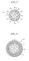
- FIG. 2 shows a cross section of the extrusion-molded article A.
- the extrusion-molded article A has a through-hole B formed in the center thereof, and 6 axial grooves Gb and 6 axial grooves Gs formed in the cylindrical surface thereof.
- the axial grooves Gb and axial grooves Gs are alternately arranged at fixed intervals in the circumferential direction of the extrusion-molded article A.
- the width of the axial groove Gb is greater than the width of the axial groove Gs
- the depth of the axial groove Gb is greater than the depth of the axial groove Gs.
- the extrusion-molded article A has a diameter of 3 to 5mm, for example, and the circumference of the extrusion-molded article A is virtually the same as the width of the heat-insulating web W.
- the heat-insulating web W can completely envelop the extrusion-molded article A.
- the paper web P has a width greater than the circumference of the heat-insulating web W enveloping the extrusion-molded article A in the form of a tube.
- the wrapping section 4 has a similar structure to the wrapping section of a cigarette manufacturing machine. Thus, while the extrusion-molded article A and heat-insulating web W are passing through the wrapping section 4 with the paper web P, the extrusion-molded article A is wrapped in the heat-insulating web W and paper web P as shown in FIG. 3, so that a heat-source rod HR is formed.
- the heat-source rod HR is cut into a specified length, so that carbon-based heat-source chips HC are obtained.
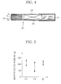
- FIG. 4 shows a cigarette-type substitute smoking article SC.
- the substitute smoking article SC comprises a heat-source chip HC, an aerosol generator (tobacco leaves) AG, and a mouth piece (filter) FT, where the chip, generator and piece are arranged in a line along the axial direction of the substitute smoking article SC.
- the heat-source chip HC When the substitute smoking article SC of FIG. 4 is smoked, the heat-source chip HC is ignited. Heat generated from the heat-source chip HC heats the aerosol generator AG, so that a smoke-like aerosol is generated from the aerosol generator AG. Such aerosol is drawn into the smoker's mouth through the mouth piece FT.
- the manufacturing machine further comprises a solvent spout apparatus 10 as shown in FIG. 1.
- the spout apparatus 10 spouts a solvent for dissolving the binder contained in the heat-insulting web W, i.e., water to the heat-insulating web W before the heat-insulating web is fed to the wrapping section 4.
- the spout apparatus 10 includes a linear air vibrator 12, and the linear vibrator 12 is disposed above the web path 2.
- the air vibrator 12 comprises a cylindrical casing 14 and a piston (not shown) fitted into the casing 14, and the piston can reciprocate in the casing 14, along the axial direction thereof, namely, along the direction perpendicular to the web path 2.
- the casing 14 has an inlet 16 and an outlet 16 at the outer surface thereof.
- the inlet 16 is connected with a compressed-air supply source 22 by a supply pipe 20.
- a pressure regulator 24, a pressure gauge 26 and a needle valve 28 are inserted in this order from the supply source 22 side.
- From the outlet 18 extends an air discharge pipe 30, and the air discharge pipe 30 has an end which opens into the atmosphere. Also in the air discharge pipe 30, a needle valve 32 is inserted.
- the piston By compressed air being supplied from the supply source 22 into the air vibrator 12 through the inlet 16 and discharged from the air vibrator 12 through the outlet 18, the piston reciprocates along one direction, or in other words, vibrates.
- the frequency and amplitude of vibration of the piston is determined by the pressure of the compressed air supplied to the inlet 16 and the discharge rate of the compressed air discharged from the outlet 18.
- the frequency and amplitude of vibration of the piston can be regulated independently, by means of the pressure regulator 24 and the needle valves 28, 32.
- a vibrating rod 34 is connected to the piston of the air vibrator 12.
- the vibrating rod 34 protrudes from the air vibrator 12 and extends across the web path 2, above the web path 2.
- a flexible nozzle 36 is attached to the vibrating rod 34.
- the flexible nozzle 36 has a distal end directed toward the heat-insulating web W on the web path 2.
- a water supply pipe 38 extends, and the water supply pipe 38 is connected with a water tank 40.
- a rate regulating pump 42 such as a gear pump is inserted in the water pipe 38. The rate regulating pump 42 can draw in water from the water tank 40 and spout the drawn-in water through the flexible nozzle 36 onto the insulating web W at a specified discharge rate.
- the flexible nozzle 36 comprises a hub part 36a at the proximal end thereof, in which the water supply pipe 38 is fitted, and a needle part 36b which extends integrally from the hub part 36a.
- the needle part 36b has flexibility.
- the vibrating rod 43 has a hole near the distal end thereof, and the hole extends through the vibrating rod 36, along a diameter of the vibrating rod 36.
- the flexible nozzle 36 is attached to the vibrating rod 34 in the manner that the needle part 36b of the flexible nozzle 36 is passed through the though-hole from above.
- the distal end of the flexible nozzle 36 reciprocates widthways relative to the insulating web W, following the vibration of the vibrating rod 34, with the needle part 36b bent.
- the flexible nozzle 36 stably receives water from the rate regulating pump 42 at a fixed rate.
- the needle part 36b of the flexible nozzle 36 easily embodies a water supply path from the rate regulating pump 42 to the distal end of the flexible nozzle 36, although the distal end of the flexible nozzle 36 reciprocates due to the vibration of the vibrating rod 34.
- the flexible nozzle 36 also functions as a stopper for preventing the vibrating rod 34 from rotating about the axis with the piston of the air vibrator 12.
- the vibrating rod 34 When the heat-insulating web W is fed to the wrapping section 4 along the web path 2, the vibrating rod 34 is vibrated and water is spouted from the distal end of the flexible nozzle 36 toward the heat-insulating web W. The water spouted this way penetrates into the upper surface of the heat-insulating web W, thereby forming a wet band H on the heat-insulating web W as shown in FIG. 1.
- the wet band H describes a continuous waveform, or in other words, a sine curve, along the longitudinal direction of the heat-insulating web W.
- the wet band H dissolves the binder such as pectin contained in the insulating web W, thereby forming a so-called adhesive application region.
- the amplitude of the wet band H is determined by the amplitude of vibration of the vibrating rod 34, and the wavelength of the wet band H is determined by the traveling speed of the heat-insulating web W and the frequency of vibration of the vibrating rod 34.
- the insulating web W with the wet band H, namely the adhesive application region formed is fed to the wrapping section 4 with the paper web P. Also the extrusion-molded article A is fed to the wrapping section 4, where the extrusion-molded article A is placed on the paper web P with the heat-insulating web W between.
- the extrusion-molded article A, heat-insulating web W and paper web P pass through the wrapping section 4, the extrusion-molded article A is continuously wrapped in the heat-insulating web W and paper web P, so that a heat-source rod HR is formed.
- the heat-insulating web W has the wet band H, namely the adhesive application region, the heat-insulating web W and the extrusion-molded article A are bonded together by the adhesive. Since the wet band H extends circumferentially relative to the extrusion-molded article A, the wet band H securely bonds the extrusion-molded article A and the heat-insulating web W together, so that the strength of bonding between the extrusion-molded article A and the heat-insulating web W is high.
- the fuel core K and the heat-insulating sheath S are firmly bonded.
- the fuel core K does not shift, or move axially relative to the heat-insulating sheath S.
- the wet band H can be formed with a small amount of spouted water. This prevents the phenomenon that water in the wet band H penetrates into the extrusion-molded article A excessively, and therefore prevents a decrease in the hardness of the outer surface of the extrusion-molded article A. Consequently, on the occasions such that the heat-source rod HR is formed or the heat-source rod HR is cut, the axial grooves Gb, Gs of the extrusion-molded article A are not deformed or little deformed. Thus, the axial grooves Gb, Gs stably maintain the groove shape which they took immediately after molding of the extruded-molded article A. Accordingly, the heat-source chip HC can have desired burning characteristics.
- FIG. 5 shows the result of measurement of bonding strength between the fuel core K and the heat-insulating sheath S, where the equal numbers of examples E1 of the heat-source chip HC according to the present invention, comparative examples C1 and comparative examples C2 of heat-source chip were prepared and measured.
- a quantity representing the bonding strength the resistance of the fuel core K to push-in relative to the heat-insulating sheath S was measured.
- the wet band H was formed by using 14ml of water per 25m of the heat-insulating web W.
- linear wet bands were formed by using 28ml and 14ml of water per 25m of the heat-insulating web W, respectively.
- an extrusion-molded article of cross section shown in FIG. 2 was cut into 12mm, and the conditions of manufacture of the extrusion-molded article were the same.
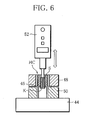
- FIG. 6 shows a measurement apparatus with which the result of measurement shown in FIG. 5 was obtained.
- the measurement apparatus has a base 44, and hollow cylindrical members 48, 50 forming a pair are arranged vertically on the base 44. Between the cylindrical members 48, 50, an annular disk 46 is interposed. The inner diameters of the cylindrical members 48, 50 are greater than the outer diameter of the heat-source chip HC, and the inner diameter of the disk 46 is greater than the outer diameter of the fuel core K of the heat-source chip HC but smaller than the outer diameter of the heat-source chip HC.
- the measurement apparatus further comprises a force gauge 52 disposed above the cylindrical members 48, 50, where the force gauge 52 can move up and down.
- the heat-source chip as a test piece is inserted into the upper cylindrical member 48 and placed on the disk 46.
- the force gauge 52 pushes onto the fuel core K of the heat-source chip HC downward at the rate of 1.5mm/s, where the maximum of the readings shown on the force gauge 52 is obtained as the resistance of the fuel core K to push-in (bonding strength between the fuel core K and the insulating sheath S).
- examples E1 (14ml) of heat-source chip according to the present invention have a greater resistance to push-in, compared with comparative examples C2 (14ml) of heat-source chip, and the resistance to push-in of examples E1 is at a similar level to the resistance to push-in of comparative examples C1 (28ml) of heat-source chip.
- the same resistance to push-in can be ensured with a smaller amount of water spouted onto the heat-insulating web W, as compared with the manufacture of the heat-source rod for obtaining comparative examples C1 of heat-source chip.
- the result of measurement in FIG. 7 was obtained using a drawing measurement apparatus 54 shown in FIG. 8.
- the drawing measurement apparatus 54 includes a suction pipe 56, and the suction pipe 56 has an inlet into which a test tube 58 can be fitted.
- the test tube 58 holds a to-be-measured fuel core K air-tightly inserted therein.
- the drawing measurement apparatus 54 draws in air through the test tube 58 at the rate of 17.5ml/s, and the resistance to drawing in the fuel core K (heat-source chip HC) is measured.
- examples E1 (14ml) of heat-source chip according to the present invention the proportion of those which have a small resistance to drawing is larger, as compared with comparative examples C1 (28ml) of heat-source chip.
- examples E1 of heat-source chip according to the present invention the axial grooves of the fuel core K well maintain the shape imparted at the time of extrusion molding.
- examples E1 of heat-source chip according to the present invention can have desired burning characteristics, which leads to a great improvement in the quality of the substitute smoking article SC.
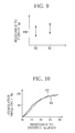
- FIGS. 9 and 10 show the result of comparison between examples E1 and E2 of heat-source chip according to the present invention, with respect to the resistance of the fuel core K to push-in and the degree of deformation of the axial grooves (resistance to drawing).
- the heat-source rods for obtaining examples E1 and E2 of heat-source chip are manufactured using different flexible nozzles.
- the flexible nozzle 36 used in the manufacture of the heat-source rod for examples E1 is 0.61mm in inner diameter
- the flexible nozzle 36 used in the manufacture of the heat-source rod for examples E2 is 0.25mm in inner diameter.
- the width of the wet band in examples E1 is greater than the width of the wet band in examples E2.
- examples E1 of heat-source chip the resistance to push-in is relatively high as compared with examples E2.
- examples E2 of heat-source chip almost no difference is seen between examples E1 and examples E2 of heat-source chip.
- the resistance to push-in in examples E1, E2 is affected by the inner diameter of the flexible nozzle 36, or in other words, the width of the wet band H, while with respect to the resistance to drawing (i.e., degree of deformation of the axial grooves), no difference is produced between examples E1 and E2.
- the spout apparatus 10 can use different types of vibrators other than the air vibrator 12, and can include a hard nozzle substituting for the flexible nozzle 36 and a flexible coupling for connecting the hard nozzle to the water supply pipe.
- the solvent spouted onto the heat-insulating web is not restricted to water, but selected appropriately according to the type of the binder contained in the heat-insulating web.
Abstract
Description
- This invention relates to a manufacturing machine for manufacturing a heat-source rod for a heat-source chip, namely, a heat-source rod for obtaining a heat-source chip for use in a smoking article substituting for a cigarette, and a method of manufacturing the same.
- The heat-source chip as mentioned above is obtained by cutting a continuous heat-source rod into a specified length. As shown in the specification of
Japanese Patent No. 3472591 - More specifically, the extrusion-molded article is fed to a wrapping section immediately after made, and therefore still in a wet or soft state, continuously wrapped in the heat-insulating web at the wrapping section and thereby formed into a heat-source rod. Then, the heat-source rod is fed to a cutting section, and at the cutting section, cut into a specified length, so that the above-mentioned heat-source chip is obtained. Thus, the heat-source chip comprises a fuel core formed from part of the extrusion-molded article, and a heat-insulating sheath formed from part of the heat-insulating web and enveloping the fuel core. The heat-source chip is then combined with other constituent elements so that the heat-source chip and other constituent elements form a substitute smoking article similar to a cigarette.
- The heat-source chip, or more exactly, the extrusion-molded article needs to have burning characteristics suitable for the substitute smoking article. In this view, the extrusion-molded article has a through-hole formed in the center thereof, and a plurality of axial grooves formed in the cylindrical surface thereof. The axial grooves are arranged at equal intervals in the circumferential direction of the extrusion-molded article.
- Meanwhile, the heat-insulating sheath of the heat-source chip needs to securely envelop the heat-source core and prevent the heat-source core from falling off the substitute smoking article. Thus, the manufacturing machine disclosed in the above-mentioned patent document includes a distribution roller. The distribution roller is disposed upstream of the wrapping section, and applies water onto the heat-insulating web as a bonding inducing agent before the heat-insulating web is fed to the wrapping section. The water applied dissolves pectin used in the heat-insulating web as a binder, and the pectin dissolved functions as an adhesive for bonding the extrusion-molded article and the heat-insulating web together. Specifically, the distribution roller applies water onto the heat-insulating web in the form of a streak extending along the longitudinal direction of the heat-insulating web, so that pectin dissolved forms a glue rail on the heat-insulating web.
- As mentioned above, the extrusion-molded article has a plurality of axial grooves in the cylindrical surface. Thus, when the extrusion-molded article is wrapped in the heat-insulating web in the wrapping section, the glue rail on the heat-insulating web may coincide with one of the axial grooves. In this case, the glue rail is not in contact with the cylindrical surface of the extrusion-molded article and therefore does not effectively function as an adhesive for bonding the extrusion-molded article and the heat-insulating web together.
- If a heat-source chip is obtained from a heat-source rod manufactured this way, the heat-source chip is defective with insufficient bonding between the fuel core and the heat-insulating sheath, and a substitute smoking article with such heat-source chip incorporated is also defective. If a shock is applied to such defective substitute smoking article in the axial direction during transportation or when it is held in a consumer's hand, the shock may cause axial shift of the fuel core of the heat-source chip. As a result of such axial shift, the fuel core protrudes from an end of the heat-insulating sheath, namely an end of the substitute smoking article, or plunges toward the constituent element adjacent to the heat-source chip within the substitute smoking article. Such protrusion or plunge of the fuel core makes the smoking of the substitute smoking article difficult.
- In order to avoid this problem, it is conceivable to increase the number of glue rails formed on the heat-insulating web, or increase the width of the glue rail. In either case, however, a large amount of water is applied onto the heat-insulating web, so that an increased amount of water penetrates into the cylindrical surface of the extrusion-molded article, which decreases the hardness of the outer surface of the extrusion-molded article to a great degree.
- When fed to the wrapping section, the extrusion-molded article is still in a wet and soft state and therefore contains a large amount of water. If, in addition to this water contained, a large amount of water penetrates into the extrusion-molded article from the heat-insulating web, the extrusion-molded article cannot maintain the external shape thereof. Thus, when the extrusion-molded article is wrapped in the heat-insulating web or when the heat-source rod is cut, the axial grooves of the extrusion-molded article may be deformed, or crushed and blocked. Deforming or crushing the axial grooves like this reduces the flow-passage cross-sectional area of the axial grooves to a great degree, so that the heat-source chip cannot have burning characteristics required.
- The primary object of this invention is to provide a manufacturing machine and manufacturing method capable of ensuring sufficient strength of bonding between the extrusion-molded article and the heat-insulating web and imparting desired burning characteristics to the heat-source rod, and therefore, to the heat-source chip.
- In order to achieve this object, a manufacturing machine for manufacturing a heat-source rod according to the present invention comprises a web path for feeding a heat-insulating web made of heat-insulating fiber bound by a binder; a wrapping section disposed downstream of the web path, for receiving the heat-insulating web from the web path and a rod-like extrusion-molded article made from a combustible material with a plurality of axial grooves in a cylindrical surface thereof on one side of the received heat-insulating web, and continuously wrapping the extrusion-molded article in the heat-insulating web, thereby forming a heat-source rod, while the heat-insulating web and the extrusion-molded article are passing through the wrapping section; and a solvent spout apparatus for spouting a solvent for dissolving the binder onto said side of the heat-insulating web, thereby forming a wet band of the solvent on said side of the heat-insulating web, before the heat-insulating web is fed to the wrapping section, wherein the wet band has a waveform continuing along the longitudinal direction of the heat-insulating web.
- The wet band of the heat-insulating web dissolves the binder contained in the heat-insulating web, thereby forming an adhesive for bonding the extrusion-molded article, or in other words, a streak-like adhesive region. When the extrusion-molded article is wrapped in the heat-insulating web so that the fuel rod is formed, the streak-like adhesive region bonds the extrusion-molded article and the heat-insulating web together. The wet band, namely the streak-like adhesive region extends circumferentially relative to the extrusion-molded article, crossing the axial grooves of the extrusion-molded article, and therefore securely bonds the extrusion-molded article and the heat-insulating web together and increases the bonding strength between them. This allows the wet band to be formed with a small amount of the solvent. Thus, the hardness of the outer surface of the extrusion-molded article is sufficiently maintained, which ensures that the heat-source chip obtained from the heat-source rod has burning characteristics required.
- Specifically, the solvent spout apparatus can include a vibrator disposed above the web path and having a vibrating member which vibrates transversely relative to the web path; a nozzle attached to the vibrating member, for spouting the solvent to the heat-insulating web; and a supply source for supplying the solvent to the nozzle. Desirably, the vibrator is an air vibrator capable of regulating the amplitude and frequency of vibration of the vibrating member, independently.
- Further, the nozzle is a flexible nozzle attached to the vibrating member to extend across the vibrating member, and the flexible nozzle has an end which reciprocates transversely relative to the web path due to the vibration of the vibrating member.
- When the heat-insulating web is fed along the web path, the nozzle spouts the solvent onto one side of the heat-insulating web, reciprocating widthways relative to the heat-insulating web, due to the vibration of the vibrating member of the vibrator. By this, the above-mentioned wet band is formed on the heat-insulating web. The amplitude and wavelength of the wet band are determined by the frequency and amplitude of vibration of the vibrating member and the traveling speed of the heat-insulating web.
- The waveform wet band is easily formed by combining the traveling of the heat-insulating web and the vibration of the vibrating member. The use of the flexible nozzle facilitates the connection between a pipe extending from the solvent supply source and the flexible nozzle.
- The above-described manufacturing machine can further comprise a feed path for feeding a paper web to the wrapping section, where the paper web envelops the extrusion-molded article with the heat-insulating web therein.
- The present invention further provides a method of manufacturing a heat-source rod, which method comprises a first step of feeding a rod-like extrusion-molded article made from a combustible material with a plurality of axial grooves in a cylindrical surface thereof and a heat-insulating web made of heat-insulating fiber bound by a binder, to a wrapping section, and placing the extrusion-molded article on one side of the heat-insulating web; a second step of wrapping the extrusion-molded article in the heat-insulating web, thereby forming a heat-source rod, while the heat-insulating web and the extrusion-molded article are passing through the wrapping section; and a third step of spouting a solvent for dissolving the binder onto said side of the heat-insulating web in the process of the heat-insulating web being fed to the wrapping section, thereby forming a wet band of the solvent on said side of the heat-insulating web, where the wet band has a waveform continuing along the longitudinal direction of the heat-insulating web.
- The third step can use a nozzle for spouting the solvent to the heat-insulating web, where an end of the nozzle reciprocates transversely relative to the heat-insulating web when the heat-insulating web is fed to the wrapping section. The first step can further include feeding a paper web to the wrapping section, where the paper web envelops the extrusion-molded article with the heat-insulating web therein.
-
- [FIG. 1] A diagram schematically showing a partial structure of an embodiment of manufacturing machine.
- [FIG. 2] A transverse cross-sectional view of an extrusion-molded article used for forming a heat-source rod.
- [FIG. 3] A diagram showing an end face of a heat-source rod (heat-source chip).
- [FIG. 4] A longitudinal cross-sectional view of a substitute smoking article including a heat-source chip.
- [FIG. 5] A graph comparing an example of heat-source chip according to the present invention and comparative examples of heat-source chip with respect to the fuel core's resistance to push-in.
- [FIG. 6] A diagram showing an example of a measurement apparatus for measuring the resistance to push-in.
- [FIG. 7] A graph comparing an example of heat-source chip according to the present invention and comparative examples of heat-source chip in respect of the resistance to drawing.
- [FIG. 8] A diagram for explaining how to measure the resistance to drawing.
- [FIG. 9] A graph comparing two examples of heat-source chip according to the present invention with respect to the fuel core's resistance to push-in.
- [FIG. 10] A graph comparing two examples of heat-source chip according to the present invention with respect to the resistance to drawing.
- A manufacturing machine for manufacturing a heat-source rod shown in FIG. 1 has a
web path 2. Theweb path 2 extends to near a wrapping section 4 to feed a heat-insulating web W to the wrapping section 4. The heat-insulating web W is made of unwoven glass-fiber fabric containing a binder such as pectin for binding the glass fiber, and unwound from a web roll (not shown) and fed along theweb path 2. - To the wrapping section 4, a rod-like extrusion-molded article A and a paper web P are fed in addition to the heat-insulating web W. At an inlet end of the wrapping section 4, the heat-insulating web W and the extrusion-molded article A are laid on the paper web P in this order.
- The extrusion-molded article A is molded from a combustible mixture by an
extruder 6, and fed to the wrapping section 4 along a predetermined guide path. Specifically, the mixture comprises carbon powder as a fuel, a combustion regulator, tobacco powder, a binder, water, etc., and obtained by mixing these materials. The combustion regulator includes any of graphite, calcium carbonate, sodium carbonate and the like, or a combination of such substances. The binder includes any of ammonium alginate, methylcellulose, guar gum, pectin and the like, or a combination of such substances. - FIG. 2 shows a cross section of the extrusion-molded article A. The extrusion-molded article A has a through-hole B formed in the center thereof, and 6 axial grooves Gb and 6 axial grooves Gs formed in the cylindrical surface thereof. The axial grooves Gb and axial grooves Gs are alternately arranged at fixed intervals in the circumferential direction of the extrusion-molded article A. As clear from FIG. 2, the width of the axial groove Gb is greater than the width of the axial groove Gs, and the depth of the axial groove Gb is greater than the depth of the axial groove Gs.
- The extrusion-molded article A has a diameter of 3 to 5mm, for example, and the circumference of the extrusion-molded article A is virtually the same as the width of the heat-insulating web W. Thus, the heat-insulating web W can completely envelop the extrusion-molded article A. Meanwhile, the paper web P has a width greater than the circumference of the heat-insulating web W enveloping the extrusion-molded article A in the form of a tube. When the paper web P is wrapped around the tubular heat-insulating web W, the opposite side edges of the paper web P overlap with a lap glue as an adhesive between.
- The wrapping section 4 has a similar structure to the wrapping section of a cigarette manufacturing machine. Thus, while the extrusion-molded article A and heat-insulating web W are passing through the wrapping section 4 with the paper web P, the extrusion-molded article A is wrapped in the heat-insulating web W and paper web P as shown in FIG. 3, so that a heat-source rod HR is formed.
- Then, in a cutting section (not shown) disposed downstream of the wrapping section 4, the heat-source rod HR is cut into a specified length, so that carbon-based heat-source chips HC are obtained.
- FIG. 4 shows a cigarette-type substitute smoking article SC. The substitute smoking article SC comprises a heat-source chip HC, an aerosol generator (tobacco leaves) AG, and a mouth piece (filter) FT, where the chip, generator and piece are arranged in a line along the axial direction of the substitute smoking article SC.
- When the substitute smoking article SC of FIG. 4 is smoked, the heat-source chip HC is ignited. Heat generated from the heat-source chip HC heats the aerosol generator AG, so that a smoke-like aerosol is generated from the aerosol generator AG. Such aerosol is drawn into the smoker's mouth through the mouth piece FT.
- In manufacturing the heat-source rod HR, in order to securely bond the extrusion-molded article A and the heat-insulating web W together, the manufacturing machine further comprises a
solvent spout apparatus 10 as shown in FIG. 1. Thespout apparatus 10 spouts a solvent for dissolving the binder contained in the heat-insulting web W, i.e., water to the heat-insulating web W before the heat-insulating web is fed to the wrapping section 4. - Specifically, the
spout apparatus 10 includes alinear air vibrator 12, and thelinear vibrator 12 is disposed above theweb path 2. Theair vibrator 12 comprises acylindrical casing 14 and a piston (not shown) fitted into thecasing 14, and the piston can reciprocate in thecasing 14, along the axial direction thereof, namely, along the direction perpendicular to theweb path 2. - The
casing 14 has aninlet 16 and anoutlet 16 at the outer surface thereof. Theinlet 16 is connected with a compressed-air supply source 22 by asupply pipe 20. In thesupply pipe 20, apressure regulator 24, apressure gauge 26 and aneedle valve 28 are inserted in this order from thesupply source 22 side. From theoutlet 18 extends anair discharge pipe 30, and theair discharge pipe 30 has an end which opens into the atmosphere. Also in theair discharge pipe 30, aneedle valve 32 is inserted. - By compressed air being supplied from the
supply source 22 into theair vibrator 12 through theinlet 16 and discharged from theair vibrator 12 through theoutlet 18, the piston reciprocates along one direction, or in other words, vibrates. The frequency and amplitude of vibration of the piston is determined by the pressure of the compressed air supplied to theinlet 16 and the discharge rate of the compressed air discharged from theoutlet 18. Thus, the frequency and amplitude of vibration of the piston can be regulated independently, by means of thepressure regulator 24 and theneedle valves - A vibrating
rod 34 is connected to the piston of theair vibrator 12. The vibratingrod 34 protrudes from theair vibrator 12 and extends across theweb path 2, above theweb path 2. - A
flexible nozzle 36 is attached to the vibratingrod 34. Theflexible nozzle 36 has a distal end directed toward the heat-insulating web W on theweb path 2. From the proximal end of theflexible nozzle 36, awater supply pipe 38 extends, and thewater supply pipe 38 is connected with awater tank 40. In thewater pipe 38, arate regulating pump 42 such as a gear pump is inserted. Therate regulating pump 42 can draw in water from thewater tank 40 and spout the drawn-in water through theflexible nozzle 36 onto the insulating web W at a specified discharge rate. - More specifically, the
flexible nozzle 36 comprises ahub part 36a at the proximal end thereof, in which thewater supply pipe 38 is fitted, and aneedle part 36b which extends integrally from thehub part 36a. Theneedle part 36b has flexibility. Meanwhile, the vibrating rod 43 has a hole near the distal end thereof, and the hole extends through the vibratingrod 36, along a diameter of the vibratingrod 36. Theflexible nozzle 36 is attached to the vibratingrod 34 in the manner that theneedle part 36b of theflexible nozzle 36 is passed through the though-hole from above. - As the
air vibrator 12 is driven so that the vibratingrod 34 vibrates, the distal end of theflexible nozzle 36 reciprocates widthways relative to the insulating web W, following the vibration of the vibratingrod 34, with theneedle part 36b bent. In spite of the bending of theneedle part 36b, theflexible nozzle 36 stably receives water from therate regulating pump 42 at a fixed rate. Thus, theneedle part 36b of theflexible nozzle 36 easily embodies a water supply path from therate regulating pump 42 to the distal end of theflexible nozzle 36, although the distal end of theflexible nozzle 36 reciprocates due to the vibration of the vibratingrod 34. - Even when the amplitude or frequency of vibration of the vibrating
rod 34 is changed, theneedle part 36b easily follows the change due to its flexibility. - The
flexible nozzle 36 also functions as a stopper for preventing the vibratingrod 34 from rotating about the axis with the piston of theair vibrator 12. - When the heat-insulating web W is fed to the wrapping section 4 along the
web path 2, the vibratingrod 34 is vibrated and water is spouted from the distal end of theflexible nozzle 36 toward the heat-insulating web W. The water spouted this way penetrates into the upper surface of the heat-insulating web W, thereby forming a wet band H on the heat-insulating web W as shown in FIG. 1. The wet band H describes a continuous waveform, or in other words, a sine curve, along the longitudinal direction of the heat-insulating web W. - The wet band H dissolves the binder such as pectin contained in the insulating web W, thereby forming a so-called adhesive application region. The amplitude of the wet band H is determined by the amplitude of vibration of the vibrating
rod 34, and the wavelength of the wet band H is determined by the traveling speed of the heat-insulating web W and the frequency of vibration of the vibratingrod 34. - The insulating web W with the wet band H, namely the adhesive application region formed is fed to the wrapping section 4 with the paper web P. Also the extrusion-molded article A is fed to the wrapping section 4, where the extrusion-molded article A is placed on the paper web P with the heat-insulating web W between. When the extrusion-molded article A, heat-insulating web W and paper web P pass through the wrapping section 4, the extrusion-molded article A is continuously wrapped in the heat-insulating web W and paper web P, so that a heat-source rod HR is formed.
- At this stage, since the heat-insulating web W has the wet band H, namely the adhesive application region, the heat-insulating web W and the extrusion-molded article A are bonded together by the adhesive. Since the wet band H extends circumferentially relative to the extrusion-molded article A, the wet band H securely bonds the extrusion-molded article A and the heat-insulating web W together, so that the strength of bonding between the extrusion-molded article A and the heat-insulating web W is high.
- Thus, also in the heat-source chip HC obtained by cutting the heat-source rod HR, the fuel core K and the heat-insulating sheath S are firmly bonded. Thus, after the substitute smoking article including the heat-source chip HC is produced, even if a shock is applied to the substitute smoking article SC in the axial direction during transportation or when it is held in a consumer's hand, the fuel core K does not shift, or move axially relative to the heat-insulating sheath S.
- Since the strength of bonding between the fuel core K and the heat-insulating sheath S is high for the reason mentioned above, the wet band H can be formed with a small amount of spouted water. This prevents the phenomenon that water in the wet band H penetrates into the extrusion-molded article A excessively, and therefore prevents a decrease in the hardness of the outer surface of the extrusion-molded article A. Consequently, on the occasions such that the heat-source rod HR is formed or the heat-source rod HR is cut, the axial grooves Gb, Gs of the extrusion-molded article A are not deformed or little deformed. Thus, the axial grooves Gb, Gs stably maintain the groove shape which they took immediately after molding of the extruded-molded article A. Accordingly, the heat-source chip HC can have desired burning characteristics.
- FIG. 5 shows the result of measurement of bonding strength between the fuel core K and the heat-insulating sheath S, where the equal numbers of examples E1 of the heat-source chip HC according to the present invention, comparative examples C1 and comparative examples C2 of heat-source chip were prepared and measured. Here, as a quantity representing the bonding strength, the resistance of the fuel core K to push-in relative to the heat-insulating sheath S was measured.
- In the manufacture of the heat-source rod HR for obtaining examples E1 of the heat-source chip HC, the wet band H was formed by using 14ml of water per 25m of the heat-insulating web W. Meanwhile, in the manufacture of heat-source rods for obtaining comparative examples C1 and comparative examples C2 of heat-source chip, linear wet bands were formed by using 28ml and 14ml of water per 25m of the heat-insulating web W, respectively. In the manufacture of any of example E1 and comparative examples C1, C2 of heat-source chip, an extrusion-molded article of cross section shown in FIG. 2 was cut into 12mm, and the conditions of manufacture of the extrusion-molded article were the same.
- FIG. 6 shows a measurement apparatus with which the result of measurement shown in FIG. 5 was obtained.
- The measurement apparatus has a
base 44, and hollowcylindrical members base 44. Between thecylindrical members annular disk 46 is interposed. The inner diameters of thecylindrical members disk 46 is greater than the outer diameter of the fuel core K of the heat-source chip HC but smaller than the outer diameter of the heat-source chip HC. The measurement apparatus further comprises aforce gauge 52 disposed above thecylindrical members force gauge 52 can move up and down. - As shown in FIG. 6, the heat-source chip as a test piece is inserted into the upper
cylindrical member 48 and placed on thedisk 46. In this state, theforce gauge 52 pushes onto the fuel core K of the heat-source chip HC downward at the rate of 1.5mm/s, where the maximum of the readings shown on theforce gauge 52 is obtained as the resistance of the fuel core K to push-in (bonding strength between the fuel core K and the insulating sheath S). - As clear from FIG. 5, examples E1 (14ml) of heat-source chip according to the present invention have a greater resistance to push-in, compared with comparative examples C2 (14ml) of heat-source chip, and the resistance to push-in of examples E1 is at a similar level to the resistance to push-in of comparative examples C1 (28ml) of heat-source chip. This means that in the manufacture of the heat-source rod for obtaining examples E1 of heat-source chip, the same resistance to push-in can be ensured with a smaller amount of water spouted onto the heat-insulating web W, as compared with the manufacture of the heat-source rod for obtaining comparative examples C1 of heat-source chip.
- Further, regarding the equal numbers of examples E1 and comparative examples C1 of heat-source chip, the resistance to drawing was measured as a quantity representing the degree of deformation of the axial grooves of the heat-source chip. The result of measurement is shown in terms of cumulative frequency in FIG. 7.
- The result of measurement in FIG. 7 was obtained using a
drawing measurement apparatus 54 shown in FIG. 8. The drawingmeasurement apparatus 54 includes asuction pipe 56, and thesuction pipe 56 has an inlet into which atest tube 58 can be fitted. Thetest tube 58 holds a to-be-measured fuel core K air-tightly inserted therein. After thetest tube 38 is fitted into the inlet of thesuction pipe 56, the drawingmeasurement apparatus 54 draws in air through thetest tube 58 at the rate of 17.5ml/s, and the resistance to drawing in the fuel core K (heat-source chip HC) is measured. - As clear from FIG. 7, regarding examples E1 (14ml) of heat-source chip according to the present invention, the proportion of those which have a small resistance to drawing is larger, as compared with comparative examples C1 (28ml) of heat-source chip. This indicates that in examples E1 of heat-source chip according to the present invention, the axial grooves of the fuel core K well maintain the shape imparted at the time of extrusion molding. Thus, examples E1 of heat-source chip according to the present invention can have desired burning characteristics, which leads to a great improvement in the quality of the substitute smoking article SC.
- FIGS. 9 and 10 show the result of comparison between examples E1 and E2 of heat-source chip according to the present invention, with respect to the resistance of the fuel core K to push-in and the degree of deformation of the axial grooves (resistance to drawing).
- The heat-source rods for obtaining examples E1 and E2 of heat-source chip are manufactured using different flexible nozzles. Specifically, the
flexible nozzle 36 used in the manufacture of the heat-source rod for examples E1 is 0.61mm in inner diameter, while theflexible nozzle 36 used in the manufacture of the heat-source rod for examples E2 is 0.25mm in inner diameter. Thus, the width of the wet band in examples E1 is greater than the width of the wet band in examples E2. - As clear from FIG. 9, in examples E1 of heat-source chip, the resistance to push-in is relatively high as compared with examples E2. Meanwhile, as shown in FIG. 10, with respect to the resistance to drawing, almost no difference is seen between examples E1 and examples E2 of heat-source chip. This means that provided that the amount of water spouted is the same, the resistance to push-in in examples E1, E2 is affected by the inner diameter of the
flexible nozzle 36, or in other words, the width of the wet band H, while with respect to the resistance to drawing (i.e., degree of deformation of the axial grooves), no difference is produced between examples E1 and E2. - The present invention is not restricted to the above-described embodiment. Various modifications can be made to it.
- For example, the
spout apparatus 10 can use different types of vibrators other than theair vibrator 12, and can include a hard nozzle substituting for theflexible nozzle 36 and a flexible coupling for connecting the hard nozzle to the water supply pipe. - Further, the solvent spouted onto the heat-insulating web is not restricted to water, but selected appropriately according to the type of the binder contained in the heat-insulating web.
Claims (8)
- A manufacturing machine for manufacturing a heat-source rod, comprising:a web path for feeding a heat-insulating web made of heat-insulating fiber bound by a binder,a wrapping section disposed downstream of said web path, for receiving the heat-insulating web from said web path and a rod-like extrusion-molded article made from a combustible material with a plurality of axial grooves in a cylindrical surface thereof on one side of the received heat-insulating web, and continuously wrapping the extrusion-molded article in the heat-insulating web, thereby forming a heat-source rod, while the heat-insulating web and the extrusion-molded article are passing through said wrapping section, anda solvent spout apparatus for spouting a solvent for dissolving the binder onto said side of the heat-insulating web, thereby forming a wet band of the solvent on said side of the heat-insulating web, before the heat-insulating web is fed to said wrapping section, whereinthe wet band has a waveform continuing along the longitudinal direction of the heat-insulating web.
- The manufacturing machine according to claim 1, wherein
said solvent spout apparatus includes
a vibrator disposed above said web path and having a vibrating member which vibrates transversely relative to said web path,
a nozzle attached to the vibrating member, for spouting the solvent to the heat-insulating web, and
a supply source for supplying the solvent to the nozzle. - The manufacturing machine according to claim 2, wherein
the vibrator is an air vibrator capable of regulating the amplitude and frequency of vibration of the vibrating member, independently. - The manufacturing machine according to claim 2, wherein
the nozzle is a flexible nozzle attached to the vibrating member to extend across the vibrating member, and the flexible nozzle has an end which reciprocates transversely relative to said web path due to the vibration of the vibrating member. - The manufacturing machine according to claim 1, further comprising a feed path for feeding a paper web to said wrapping section, wherein the paper web envelops the extrusion-molded article with the heat-insulating web.
- A method of manufacturing a heat-source rod, comprising:a first step of feeding a rod-like extrusion-molded article made from a combustible material with a plurality of axial grooves in a cylindrical surface thereof and a heat-insulating web of heat-insulating fiber bound by a binder, to a wrapping section, and placing the extrusion-molded article on one side of the heat-insulating web,a second step of wrapping the extrusion-molded article in the heat-insulating web, thereby forming a heat-source rod, while the heat-insulating web and the extrusion-molded article are passing through the wrapping section, anda third step of spouting a solvent for dissolving the binder onto said side of the heat-insulating web in the process of the heat-insulating web being fed to the wrapping section, thereby forming a wet band of the solvent on said side of the heat-insulating web, where the wet band has a waveform continuing along the longitudinal direction of the heat-insulating web.
- The manufacturing method according to claim 6, wherein
said third step uses a nozzle for spouting the solvent to the heat-insulating web, and an end of the nozzle reciprocates transversely relative to the heat-insulating web when the heat-insulating web is fed to the wrapping section. - The manufacturing method according to claim 7, wherein
said first step further includes feeding a paper web to the wrapping section, where the paper web envelops the extrusion-molded article with the heat-insulating web therein.
Applications Claiming Priority (2)
| Application Number | Priority Date | Filing Date | Title |
|---|---|---|---|
| JP2004309743 | 2004-10-25 | ||
| PCT/JP2005/019015 WO2006046422A1 (en) | 2004-10-25 | 2005-10-17 | Heat source rod production machine and its production method |
Publications (3)
| Publication Number | Publication Date |
|---|---|
| EP1808087A1 true EP1808087A1 (en) | 2007-07-18 |
| EP1808087A4 EP1808087A4 (en) | 2012-05-09 |
| EP1808087B1 EP1808087B1 (en) | 2013-01-16 |
Family
ID=36227665
Family Applications (1)
| Application Number | Title | Priority Date | Filing Date |
|---|---|---|---|
| EP05793434A Active EP1808087B1 (en) | 2004-10-25 | 2005-10-17 | Heat source rod production machine and its production method |
Country Status (11)
| Country | Link |
|---|---|
| US (1) | US7692123B2 (en) |
| EP (1) | EP1808087B1 (en) |
| JP (1) | JP4454035B2 (en) |
| KR (1) | KR100838419B1 (en) |
| CN (1) | CN100539882C (en) |
| CA (1) | CA2584759C (en) |
| ES (1) | ES2399411T3 (en) |
| HK (1) | HK1104769A1 (en) |
| RU (1) | RU2345686C1 (en) |
| UA (1) | UA88657C2 (en) |
| WO (1) | WO2006046422A1 (en) |
Cited By (16)
| Publication number | Priority date | Publication date | Assignee | Title |
|---|---|---|---|---|
| WO2013131764A1 (en) * | 2012-03-05 | 2013-09-12 | British American Tobacco (Investments) Limited | Heating smokable material |
| WO2015022597A1 (en) * | 2013-08-12 | 2015-02-19 | International Tobacco Machinery Poland Sp. Z O.O. | Method and apparatus for application of glue |
| WO2015123558A2 (en) | 2014-02-13 | 2015-08-20 | R. J. Reynolds Tobacco Company | Method for assembling a cartridge for a smoking article |
| WO2015123202A1 (en) | 2014-02-11 | 2015-08-20 | R. J. Reynolds Tobacco Company | Igniter apparatus for a smoking article, and associated method |
| WO2015127412A1 (en) | 2014-02-24 | 2015-08-27 | R.J. Reynolds Tobacco Company | Electronic coupon system |
| WO2015164255A1 (en) | 2014-04-25 | 2015-10-29 | R.J. Reynolds Tobacco Company | Data translator |
| WO2017004185A2 (en) | 2015-06-30 | 2017-01-05 | R. J. Reynolds Tobacco Company | Heat generation segment for an aerosol-generation system of a smoking article |
| WO2017040608A2 (en) | 2015-08-31 | 2017-03-09 | R. J. Reynolds Tobacco Company | Smoking article |
| WO2017042297A1 (en) * | 2015-09-11 | 2017-03-16 | Philip Morris Products S.A. | Multi-segment component for an aerosol-generating article |
| WO2017098464A1 (en) | 2015-12-10 | 2017-06-15 | R. J. Reynolds Tobacco Company | Smoking article |
| US9788571B2 (en) | 2013-09-25 | 2017-10-17 | R.J. Reynolds Tobacco Company | Heat generation apparatus for an aerosol-generation system of a smoking article, and associated smoking article |
| US10194691B2 (en) | 2016-05-25 | 2019-02-05 | R.J. Reynolds Tobacco Company | Non-combusting smoking article with thermochromatic label |
| WO2019077530A1 (en) | 2017-10-19 | 2019-04-25 | Rai Strategic Holdings, Inc. | Colorimetric aerosol and gas detection for aerosol delivery device |
| WO2019162815A1 (en) | 2018-02-22 | 2019-08-29 | R. J. Reynolds Tobacco Company | A system for debossing a heat generation member, a smoking article including the debossed heat generation member, and a related method |
| US11717018B2 (en) | 2016-02-24 | 2023-08-08 | R.J. Reynolds Tobacco Company | Smoking article comprising aerogel |
| US11744296B2 (en) | 2015-12-10 | 2023-09-05 | R. J. Reynolds Tobacco Company | Smoking article |
Families Citing this family (52)
| Publication number | Priority date | Publication date | Assignee | Title |
|---|---|---|---|---|
| UA91206C2 (en) | 2004-12-15 | 2010-07-12 | Джапан Тобакко Інк. | Device for producing stick-like smoking articles |
| US7726320B2 (en) | 2006-10-18 | 2010-06-01 | R. J. Reynolds Tobacco Company | Tobacco-containing smoking article |
| US9861772B2 (en) | 2010-05-15 | 2018-01-09 | Rai Strategic Holdings, Inc. | Personal vaporizing inhaler cartridge |
| US9999250B2 (en) | 2010-05-15 | 2018-06-19 | Rai Strategic Holdings, Inc. | Vaporizer related systems, methods, and apparatus |
| US10159278B2 (en) | 2010-05-15 | 2018-12-25 | Rai Strategic Holdings, Inc. | Assembly directed airflow |
| US8757147B2 (en) | 2010-05-15 | 2014-06-24 | Minusa Holdings Llc | Personal vaporizing inhaler with internal light source |
| US9095175B2 (en) | 2010-05-15 | 2015-08-04 | R. J. Reynolds Tobacco Company | Data logging personal vaporizing inhaler |
| US10136672B2 (en) | 2010-05-15 | 2018-11-27 | Rai Strategic Holdings, Inc. | Solderless directly written heating elements |
| US9259035B2 (en) | 2010-05-15 | 2016-02-16 | R. J. Reynolds Tobacco Company | Solderless personal vaporizing inhaler |
| US9743691B2 (en) | 2010-05-15 | 2017-08-29 | Rai Strategic Holdings, Inc. | Vaporizer configuration, control, and reporting |
| US9078473B2 (en) | 2011-08-09 | 2015-07-14 | R.J. Reynolds Tobacco Company | Smoking articles and use thereof for yielding inhalation materials |
| US20130255702A1 (en) | 2012-03-28 | 2013-10-03 | R.J. Reynolds Tobacco Company | Smoking article incorporating a conductive substrate |
| CN104320982B (en) * | 2012-04-02 | 2017-03-01 | 菲利普莫里斯生产公司 | The method manufacturing combustible heat source |
| EP2676559A1 (en) | 2012-06-21 | 2013-12-25 | Philip Morris Products S.A. | Method of manufacturing a combustible heat source with a barrier |
| US10004259B2 (en) | 2012-06-28 | 2018-06-26 | Rai Strategic Holdings, Inc. | Reservoir and heater system for controllable delivery of multiple aerosolizable materials in an electronic smoking article |
| US8881737B2 (en) | 2012-09-04 | 2014-11-11 | R.J. Reynolds Tobacco Company | Electronic smoking article comprising one or more microheaters |
| US8910639B2 (en) | 2012-09-05 | 2014-12-16 | R. J. Reynolds Tobacco Company | Single-use connector and cartridge for a smoking article and related method |
| US9854841B2 (en) | 2012-10-08 | 2018-01-02 | Rai Strategic Holdings, Inc. | Electronic smoking article and associated method |
| US10117460B2 (en) | 2012-10-08 | 2018-11-06 | Rai Strategic Holdings, Inc. | Electronic smoking article and associated method |
| US8910640B2 (en) | 2013-01-30 | 2014-12-16 | R.J. Reynolds Tobacco Company | Wick suitable for use in an electronic smoking article |
| US10031183B2 (en) | 2013-03-07 | 2018-07-24 | Rai Strategic Holdings, Inc. | Spent cartridge detection method and system for an electronic smoking article |
| US9918495B2 (en) | 2014-02-28 | 2018-03-20 | Rai Strategic Holdings, Inc. | Atomizer for an aerosol delivery device and related input, aerosol production assembly, cartridge, and method |
| US9277770B2 (en) | 2013-03-14 | 2016-03-08 | R. J. Reynolds Tobacco Company | Atomizer for an aerosol delivery device formed from a continuously extending wire and related input, cartridge, and method |
| US9491974B2 (en) | 2013-03-15 | 2016-11-15 | Rai Strategic Holdings, Inc. | Heating elements formed from a sheet of a material and inputs and methods for the production of atomizers |
| US9423152B2 (en) | 2013-03-15 | 2016-08-23 | R. J. Reynolds Tobacco Company | Heating control arrangement for an electronic smoking article and associated system and method |
| US9220302B2 (en) | 2013-03-15 | 2015-12-29 | R.J. Reynolds Tobacco Company | Cartridge for an aerosol delivery device and method for assembling a cartridge for a smoking article |
| US9609893B2 (en) | 2013-03-15 | 2017-04-04 | Rai Strategic Holdings, Inc. | Cartridge and control body of an aerosol delivery device including anti-rotation mechanism and related method |
| EP3001917A4 (en) * | 2013-07-17 | 2017-01-25 | Japan Tobacco Inc. | Rod member extrusion-molding system and extrusion-molding method therefor |
| US11229239B2 (en) | 2013-07-19 | 2022-01-25 | Rai Strategic Holdings, Inc. | Electronic smoking article with haptic feedback |
| US10172387B2 (en) | 2013-08-28 | 2019-01-08 | Rai Strategic Holdings, Inc. | Carbon conductive substrate for electronic smoking article |
| WO2015046384A1 (en) * | 2013-09-30 | 2015-04-02 | 日本たばこ産業株式会社 | Flavor inhalator |
| US9839237B2 (en) | 2013-11-22 | 2017-12-12 | Rai Strategic Holdings, Inc. | Reservoir housing for an electronic smoking article |
| US9974334B2 (en) | 2014-01-17 | 2018-05-22 | Rai Strategic Holdings, Inc. | Electronic smoking article with improved storage of aerosol precursor compositions |
| US10575558B2 (en) | 2014-02-03 | 2020-03-03 | Rai Strategic Holdings, Inc. | Aerosol delivery device comprising multiple outer bodies and related assembly method |
| US9451791B2 (en) | 2014-02-05 | 2016-09-27 | Rai Strategic Holdings, Inc. | Aerosol delivery device with an illuminated outer surface and related method |
| US20150224268A1 (en) | 2014-02-07 | 2015-08-13 | R.J. Reynolds Tobacco Company | Charging Accessory Device for an Aerosol Delivery Device and Related System, Method, Apparatus, and Computer Program Product for Providing Interactive Services for Aerosol Delivery Devices |
| US9839238B2 (en) | 2014-02-28 | 2017-12-12 | Rai Strategic Holdings, Inc. | Control body for an electronic smoking article |
| US9597466B2 (en) | 2014-03-12 | 2017-03-21 | R. J. Reynolds Tobacco Company | Aerosol delivery system and related method, apparatus, and computer program product for providing control information to an aerosol delivery device via a cartridge |
| US11696604B2 (en) | 2014-03-13 | 2023-07-11 | Rai Strategic Holdings, Inc. | Aerosol delivery device and related method and computer program product for controlling an aerosol delivery device based on input characteristics |
| US9877510B2 (en) | 2014-04-04 | 2018-01-30 | Rai Strategic Holdings, Inc. | Sensor for an aerosol delivery device |
| WO2015165709A1 (en) * | 2014-04-30 | 2015-11-05 | Philip Morris Products S.A. | Consumable for an aerosol-generating device |
| US9924741B2 (en) | 2014-05-05 | 2018-03-27 | Rai Strategic Holdings, Inc. | Method of preparing an aerosol delivery device |
| US10888119B2 (en) | 2014-07-10 | 2021-01-12 | Rai Strategic Holdings, Inc. | System and related methods, apparatuses, and computer program products for controlling operation of a device based on a read request |
| US10154692B2 (en) * | 2014-11-26 | 2018-12-18 | G.D Societa' Per Azioni | Machine for producing a cartridge for an electronic cigarette |
| US10238145B2 (en) | 2015-05-19 | 2019-03-26 | Rai Strategic Holdings, Inc. | Assembly substation for assembling a cartridge for a smoking article |
| CA2992115A1 (en) | 2015-09-11 | 2017-03-16 | Philip Morris Products S.A. | Multi-segment component for an aerosol-generating article |
| US9630386B1 (en) * | 2015-10-16 | 2017-04-25 | Foxlink Image Technology Co., Ltd. | Automatic gluing mechanism and automatic gluing machine using the same |
| US10405579B2 (en) | 2016-04-29 | 2019-09-10 | Rai Strategic Holdings, Inc. | Methods for assembling a cartridge for an aerosol delivery device, and associated systems and apparatuses |
| CN106690412B (en) * | 2017-03-06 | 2023-05-26 | 云南芯韵科技开发有限公司 | Functional filter stick containing paper threads and preparation method thereof |
| US11304439B2 (en) * | 2017-05-18 | 2022-04-19 | Philip Morris Products S.A. | Method and apparatus to fold a sheet of material into a rod for an aerosol generating article |
| US20200128880A1 (en) | 2018-10-30 | 2020-04-30 | R.J. Reynolds Tobacco Company | Smoking article cartridge |
| WO2020157935A1 (en) * | 2019-01-31 | 2020-08-06 | 日本たばこ産業株式会社 | Flavor generating segment, and flavor generating article and flavor suction system comprising same |
Citations (2)
| Publication number | Priority date | Publication date | Assignee | Title |
|---|---|---|---|---|
| EP0405190A2 (en) * | 1989-06-29 | 1991-01-02 | R.J. Reynolds Tobacco Company | Extruded cigarette |
| US5020548A (en) * | 1985-08-26 | 1991-06-04 | R. J. Reynolds Tobacco Company | Smoking article with improved fuel element |
Family Cites Families (11)
| Publication number | Priority date | Publication date | Assignee | Title |
|---|---|---|---|---|
| NL286347A (en) * | 1961-12-07 | |||
| IN166122B (en) * | 1985-08-26 | 1990-03-17 | Reynolds Tobacco Co R | |
| US5076297A (en) * | 1986-03-14 | 1991-12-31 | R. J. Reynolds Tobacco Company | Method for preparing carbon fuel for smoking articles and product produced thereby |
| US5065776A (en) | 1990-08-29 | 1991-11-19 | R. J. Reynolds Tobacco Company | Cigarette with tobacco/glass fuel wrapper |
| CA2466075C (en) | 1992-03-25 | 2007-05-01 | Japan Tobacco, Inc. | Components for smoking articles and process for making same |
| JPH0677606A (en) | 1992-08-28 | 1994-03-18 | Fujitsu Ltd | Optical semiconductor device |
| US5666976A (en) | 1992-09-11 | 1997-09-16 | Philip Morris Incorporated | Cigarette and method of manufacturing cigarette for electrical smoking system |
| KR100449444B1 (en) | 1995-04-20 | 2005-08-01 | 필립모리스 프로덕츠 인코포레이티드 | Electrothermal Smoking Cigarettes, Manufacturing Method and Electrothermal Absorption Research |
| US6615840B1 (en) | 2002-02-15 | 2003-09-09 | Philip Morris Incorporated | Electrical smoking system and method |
| UA80784C2 (en) | 2003-11-13 | 2007-10-25 | Japan Tobacco Inc | Device for producing carbonic heating element |
| JP6077606B2 (en) * | 2015-07-22 | 2017-02-08 | ヤフー株式会社 | Extraction apparatus, extraction method and extraction program |
-
2005
- 2005-10-17 WO PCT/JP2005/019015 patent/WO2006046422A1/en active Application Filing
- 2005-10-17 KR KR1020077008801A patent/KR100838419B1/en active IP Right Grant
- 2005-10-17 ES ES05793434T patent/ES2399411T3/en active Active
- 2005-10-17 RU RU2007119400/12A patent/RU2345686C1/en not_active IP Right Cessation
- 2005-10-17 JP JP2006542962A patent/JP4454035B2/en not_active Expired - Fee Related
- 2005-10-17 EP EP05793434A patent/EP1808087B1/en active Active
- 2005-10-17 CN CNB2005800366144A patent/CN100539882C/en not_active Expired - Fee Related
- 2005-10-17 UA UAA200705811A patent/UA88657C2/en unknown
- 2005-10-17 CA CA2584759A patent/CA2584759C/en not_active Expired - Fee Related
-
2007
- 2007-04-24 US US11/790,247 patent/US7692123B2/en not_active Expired - Fee Related
- 2007-11-30 HK HK07113072.7A patent/HK1104769A1/en not_active IP Right Cessation
Patent Citations (2)
| Publication number | Priority date | Publication date | Assignee | Title |
|---|---|---|---|---|
| US5020548A (en) * | 1985-08-26 | 1991-06-04 | R. J. Reynolds Tobacco Company | Smoking article with improved fuel element |
| EP0405190A2 (en) * | 1989-06-29 | 1991-01-02 | R.J. Reynolds Tobacco Company | Extruded cigarette |
Non-Patent Citations (1)
| Title |
|---|
| See also references of WO2006046422A1 * |
Cited By (35)
| Publication number | Priority date | Publication date | Assignee | Title |
|---|---|---|---|---|
| WO2013131764A1 (en) * | 2012-03-05 | 2013-09-12 | British American Tobacco (Investments) Limited | Heating smokable material |
| WO2015022597A1 (en) * | 2013-08-12 | 2015-02-19 | International Tobacco Machinery Poland Sp. Z O.O. | Method and apparatus for application of glue |
| US11375745B2 (en) | 2013-09-25 | 2022-07-05 | R.J. Reynolds Tobacco Company | Heat generation apparatus for an aerosol-generation system of a smoking article, and associated smoking article |
| US10314330B2 (en) | 2013-09-25 | 2019-06-11 | R.J. Reynolds Tobacco Company | Heat generation apparatus for an aerosol-generation system of a smoking article, and associated smoking article |
| US11707083B2 (en) | 2013-09-25 | 2023-07-25 | R.J. Reynolds Tobacco Company | Heat generation apparatus for an aerosol-generation system of a smoking article, and associated smoking article |
| US9788571B2 (en) | 2013-09-25 | 2017-10-17 | R.J. Reynolds Tobacco Company | Heat generation apparatus for an aerosol-generation system of a smoking article, and associated smoking article |
| WO2015123202A1 (en) | 2014-02-11 | 2015-08-20 | R. J. Reynolds Tobacco Company | Igniter apparatus for a smoking article, and associated method |
| US10094562B2 (en) | 2014-02-11 | 2018-10-09 | R.J. Reynolds Tobacco Company | Igniter apparatus for a smoking article, and associated method |
| WO2015123558A2 (en) | 2014-02-13 | 2015-08-20 | R. J. Reynolds Tobacco Company | Method for assembling a cartridge for a smoking article |
| US10856570B2 (en) | 2014-02-13 | 2020-12-08 | Rai Strategic Holdings, Inc. | Method for assembling a cartridge for a smoking article |
| US10609961B2 (en) | 2014-02-13 | 2020-04-07 | Rai Strategic Holdings, Inc. | Method for assembling a cartridge for a smoking article |
| US9833019B2 (en) | 2014-02-13 | 2017-12-05 | Rai Strategic Holdings, Inc. | Method for assembling a cartridge for a smoking article |
| US10588352B2 (en) | 2014-02-13 | 2020-03-17 | Rai Strategic Holdings, Inc. | Method for assembling a cartridge for a smoking article |
| US10470497B2 (en) | 2014-02-13 | 2019-11-12 | Rai Strategic Holdings, Inc. | Method for assembling a cartridge for a smoking article |
| US11083857B2 (en) | 2014-02-13 | 2021-08-10 | Rai Strategic Holdings, Inc. | Method for assembling a cartridge for a smoking article |
| WO2015127412A1 (en) | 2014-02-24 | 2015-08-27 | R.J. Reynolds Tobacco Company | Electronic coupon system |
| WO2015164255A1 (en) | 2014-04-25 | 2015-10-29 | R.J. Reynolds Tobacco Company | Data translator |
| US11080739B2 (en) | 2014-04-25 | 2021-08-03 | R.J. Reynolds Tobacco Company | Data translator |
| EP3815551A2 (en) | 2015-06-30 | 2021-05-05 | R. J. Reynolds Tobacco Company | Heat generation segment for an aerosol-generation system of a smoking article |
| US10154689B2 (en) | 2015-06-30 | 2018-12-18 | R.J. Reynolds Tobacco Company | Heat generation segment for an aerosol-generation system of a smoking article |
| WO2017004185A2 (en) | 2015-06-30 | 2017-01-05 | R. J. Reynolds Tobacco Company | Heat generation segment for an aerosol-generation system of a smoking article |
| EP4338630A2 (en) | 2015-08-31 | 2024-03-20 | R. J. Reynolds Tobacco Company | Smoking article |
| WO2017040608A2 (en) | 2015-08-31 | 2017-03-09 | R. J. Reynolds Tobacco Company | Smoking article |
| WO2017042297A1 (en) * | 2015-09-11 | 2017-03-16 | Philip Morris Products S.A. | Multi-segment component for an aerosol-generating article |
| US10729169B2 (en) | 2015-09-11 | 2020-08-04 | Philip Morris Products S.A. | Multi-segment component for an aerosol-generating article |
| EP3469935A1 (en) * | 2015-09-11 | 2019-04-17 | Philip Morris Products S.a.s. | Multi-segment component for an aerosol-generating article |
| US10874140B2 (en) | 2015-12-10 | 2020-12-29 | R.J. Reynolds Tobacco Company | Smoking article |
| US10314334B2 (en) | 2015-12-10 | 2019-06-11 | R.J. Reynolds Tobacco Company | Smoking article |
| US11744296B2 (en) | 2015-12-10 | 2023-09-05 | R. J. Reynolds Tobacco Company | Smoking article |
| WO2017098464A1 (en) | 2015-12-10 | 2017-06-15 | R. J. Reynolds Tobacco Company | Smoking article |
| US11717018B2 (en) | 2016-02-24 | 2023-08-08 | R.J. Reynolds Tobacco Company | Smoking article comprising aerogel |
| US11197496B2 (en) | 2016-05-25 | 2021-12-14 | R.J. Reynolds Tobacco Company | Non-combusting smoking article with thermochromatic label |
| US10194691B2 (en) | 2016-05-25 | 2019-02-05 | R.J. Reynolds Tobacco Company | Non-combusting smoking article with thermochromatic label |
| WO2019077530A1 (en) | 2017-10-19 | 2019-04-25 | Rai Strategic Holdings, Inc. | Colorimetric aerosol and gas detection for aerosol delivery device |
| WO2019162815A1 (en) | 2018-02-22 | 2019-08-29 | R. J. Reynolds Tobacco Company | A system for debossing a heat generation member, a smoking article including the debossed heat generation member, and a related method |
Also Published As
| Publication number | Publication date |
|---|---|
| WO2006046422A1 (en) | 2006-05-04 |
| JP4454035B2 (en) | 2010-04-21 |
| KR20070054249A (en) | 2007-05-28 |
| US20070193593A1 (en) | 2007-08-23 |
| CN101048083A (en) | 2007-10-03 |
| RU2345686C1 (en) | 2009-02-10 |
| JPWO2006046422A1 (en) | 2008-05-22 |
| RU2007119400A (en) | 2008-11-27 |
| CA2584759A1 (en) | 2006-05-04 |
| EP1808087A4 (en) | 2012-05-09 |
| US7692123B2 (en) | 2010-04-06 |
| KR100838419B1 (en) | 2008-06-13 |
| CN100539882C (en) | 2009-09-16 |
| ES2399411T3 (en) | 2013-04-01 |
| UA88657C2 (en) | 2009-11-10 |
| EP1808087B1 (en) | 2013-01-16 |
| HK1104769A1 (en) | 2008-01-25 |
| CA2584759C (en) | 2011-01-04 |
Similar Documents
| Publication | Publication Date | Title |
|---|---|---|
| EP1808087B1 (en) | Heat source rod production machine and its production method | |
| CN108348000B (en) | Filter manufacturing equipment | |
| CN1512848A (en) | Filter tip assembly for cigartte and method for manufacturing the same | |
| US20230147675A1 (en) | Filter manufacturing apparatus | |
| JP6878519B2 (en) | Flavoring member, manufacturing device for flavoring member, and manufacturing method for flavoring member | |
| EP2814340B1 (en) | Apparatus and associated method for forming a filter component of a smoking article | |
| RU2714654C2 (en) | Method and apparatus for introducing elongate objects forming longitudinal axis into continuous stream of material |
Legal Events
| Date | Code | Title | Description |
|---|---|---|---|
| PUAI | Public reference made under article 153(3) epc to a published international application that has entered the european phase |
Free format text: ORIGINAL CODE: 0009012 |
|
| 17P | Request for examination filed |
Effective date: 20070419 |
|
| AK | Designated contracting states |
Kind code of ref document: A1 Designated state(s): AT BE BG CH CY CZ DE DK EE ES FI FR GB GR HU IE IS IT LI LT LU LV MC NL PL PT RO SE SI SK TR |
|
| AX | Request for extension of the european patent |
Extension state: AL BA HR MK YU |
|
| A4 | Supplementary search report drawn up and despatched |
Effective date: 20120412 |
|
| RIC1 | Information provided on ipc code assigned before grant |
Ipc: A24B 15/00 20060101AFI20120405BHEP |
|
| GRAP | Despatch of communication of intention to grant a patent |
Free format text: ORIGINAL CODE: EPIDOSNIGR1 |
|
| GRAS | Grant fee paid |
Free format text: ORIGINAL CODE: EPIDOSNIGR3 |
|
| GRAA | (expected) grant |
Free format text: ORIGINAL CODE: 0009210 |
|
| AK | Designated contracting states |
Kind code of ref document: B1 Designated state(s): AT BE BG CH CY CZ DE DK EE ES FI FR GB GR HU IE IS IT LI LT LU LV MC NL PL PT RO SE SI SK TR |
|
| AX | Request for extension of the european patent |
Extension state: AL BA HR MK YU |
|
| REG | Reference to a national code |
Ref country code: GB Ref legal event code: FG4D |
|
| REG | Reference to a national code |
Ref country code: CH Ref legal event code: NV Representative=s name: NOVAGRAAF INTERNATIONAL SA, CH Ref country code: CH Ref legal event code: EP |
|
| REG | Reference to a national code |
Ref country code: IE Ref legal event code: FG4D |
|
| REG | Reference to a national code |
Ref country code: CH Ref legal event code: NV Representative=s name: NOVAGRAAF INTERNATIONAL SA, CH Ref country code: CH Ref legal event code: EP Ref country code: AT Ref legal event code: REF Ref document number: 593378 Country of ref document: AT Kind code of ref document: T Effective date: 20130215 |
|
| REG | Reference to a national code |
Ref country code: DE Ref legal event code: R096 Ref document number: 602005037922 Country of ref document: DE Effective date: 20130314 |
|
| REG | Reference to a national code |
Ref country code: ES Ref legal event code: FG2A Ref document number: 2399411 Country of ref document: ES Kind code of ref document: T3 Effective date: 20130401 |
|
| REG | Reference to a national code |
Ref country code: GR Ref legal event code: EP Ref document number: 20130400458 Country of ref document: GR Effective date: 20130418 |
|
| REG | Reference to a national code |
Ref country code: NL Ref legal event code: T3 |
|
| REG | Reference to a national code |
Ref country code: AT Ref legal event code: MK05 Ref document number: 593378 Country of ref document: AT Kind code of ref document: T Effective date: 20130116 |
|
| REG | Reference to a national code |
Ref country code: LT Ref legal event code: MG4D |
|
| PG25 | Lapsed in a contracting state [announced via postgrant information from national office to epo] |
Ref country code: SE Free format text: LAPSE BECAUSE OF FAILURE TO SUBMIT A TRANSLATION OF THE DESCRIPTION OR TO PAY THE FEE WITHIN THE PRESCRIBED TIME-LIMIT Effective date: 20130116 Ref country code: AT Free format text: LAPSE BECAUSE OF FAILURE TO SUBMIT A TRANSLATION OF THE DESCRIPTION OR TO PAY THE FEE WITHIN THE PRESCRIBED TIME-LIMIT Effective date: 20130116 Ref country code: IS Free format text: LAPSE BECAUSE OF FAILURE TO SUBMIT A TRANSLATION OF THE DESCRIPTION OR TO PAY THE FEE WITHIN THE PRESCRIBED TIME-LIMIT Effective date: 20130516 Ref country code: BG Free format text: LAPSE BECAUSE OF FAILURE TO SUBMIT A TRANSLATION OF THE DESCRIPTION OR TO PAY THE FEE WITHIN THE PRESCRIBED TIME-LIMIT Effective date: 20130416 Ref country code: LT Free format text: LAPSE BECAUSE OF FAILURE TO SUBMIT A TRANSLATION OF THE DESCRIPTION OR TO PAY THE FEE WITHIN THE PRESCRIBED TIME-LIMIT Effective date: 20130116 |
|
| PG25 | Lapsed in a contracting state [announced via postgrant information from national office to epo] |
Ref country code: SI Free format text: LAPSE BECAUSE OF FAILURE TO SUBMIT A TRANSLATION OF THE DESCRIPTION OR TO PAY THE FEE WITHIN THE PRESCRIBED TIME-LIMIT Effective date: 20130116 Ref country code: PL Free format text: LAPSE BECAUSE OF FAILURE TO SUBMIT A TRANSLATION OF THE DESCRIPTION OR TO PAY THE FEE WITHIN THE PRESCRIBED TIME-LIMIT Effective date: 20130116 Ref country code: PT Free format text: LAPSE BECAUSE OF FAILURE TO SUBMIT A TRANSLATION OF THE DESCRIPTION OR TO PAY THE FEE WITHIN THE PRESCRIBED TIME-LIMIT Effective date: 20130516 Ref country code: LV Free format text: LAPSE BECAUSE OF FAILURE TO SUBMIT A TRANSLATION OF THE DESCRIPTION OR TO PAY THE FEE WITHIN THE PRESCRIBED TIME-LIMIT Effective date: 20130116 Ref country code: FI Free format text: LAPSE BECAUSE OF FAILURE TO SUBMIT A TRANSLATION OF THE DESCRIPTION OR TO PAY THE FEE WITHIN THE PRESCRIBED TIME-LIMIT Effective date: 20130116 |
|
| PG25 | Lapsed in a contracting state [announced via postgrant information from national office to epo] |
Ref country code: DK Free format text: LAPSE BECAUSE OF FAILURE TO SUBMIT A TRANSLATION OF THE DESCRIPTION OR TO PAY THE FEE WITHIN THE PRESCRIBED TIME-LIMIT Effective date: 20130116 Ref country code: CZ Free format text: LAPSE BECAUSE OF FAILURE TO SUBMIT A TRANSLATION OF THE DESCRIPTION OR TO PAY THE FEE WITHIN THE PRESCRIBED TIME-LIMIT Effective date: 20130116 Ref country code: EE Free format text: LAPSE BECAUSE OF FAILURE TO SUBMIT A TRANSLATION OF THE DESCRIPTION OR TO PAY THE FEE WITHIN THE PRESCRIBED TIME-LIMIT Effective date: 20130116 Ref country code: SK Free format text: LAPSE BECAUSE OF FAILURE TO SUBMIT A TRANSLATION OF THE DESCRIPTION OR TO PAY THE FEE WITHIN THE PRESCRIBED TIME-LIMIT Effective date: 20130116 |
|
| PLBE | No opposition filed within time limit |
Free format text: ORIGINAL CODE: 0009261 |
|
| STAA | Information on the status of an ep patent application or granted ep patent |
Free format text: STATUS: NO OPPOSITION FILED WITHIN TIME LIMIT |
|
| PG25 | Lapsed in a contracting state [announced via postgrant information from national office to epo] |
Ref country code: CY Free format text: LAPSE BECAUSE OF FAILURE TO SUBMIT A TRANSLATION OF THE DESCRIPTION OR TO PAY THE FEE WITHIN THE PRESCRIBED TIME-LIMIT Effective date: 20130116 |
|
| 26N | No opposition filed |
Effective date: 20131017 |
|
| REG | Reference to a national code |
Ref country code: DE Ref legal event code: R097 Ref document number: 602005037922 Country of ref document: DE Effective date: 20131017 |
|
| PG25 | Lapsed in a contracting state [announced via postgrant information from national office to epo] |
Ref country code: MC Free format text: LAPSE BECAUSE OF FAILURE TO SUBMIT A TRANSLATION OF THE DESCRIPTION OR TO PAY THE FEE WITHIN THE PRESCRIBED TIME-LIMIT Effective date: 20130116 |
|
| REG | Reference to a national code |
Ref country code: IE Ref legal event code: MM4A |
|
| PG25 | Lapsed in a contracting state [announced via postgrant information from national office to epo] |
Ref country code: IE Free format text: LAPSE BECAUSE OF NON-PAYMENT OF DUE FEES Effective date: 20131017 |
|
| PG25 | Lapsed in a contracting state [announced via postgrant information from national office to epo] |
Ref country code: HU Free format text: LAPSE BECAUSE OF FAILURE TO SUBMIT A TRANSLATION OF THE DESCRIPTION OR TO PAY THE FEE WITHIN THE PRESCRIBED TIME-LIMIT; INVALID AB INITIO Effective date: 20051017 Ref country code: LU Free format text: LAPSE BECAUSE OF NON-PAYMENT OF DUE FEES Effective date: 20131017 |
|
| REG | Reference to a national code |
Ref country code: FR Ref legal event code: PLFP Year of fee payment: 11 Ref country code: RO Ref legal event code: EPE |
|
| REG | Reference to a national code |
Ref country code: FR Ref legal event code: PLFP Year of fee payment: 12 |
|
| REG | Reference to a national code |
Ref country code: FR Ref legal event code: PLFP Year of fee payment: 13 |
|
| REG | Reference to a national code |
Ref country code: FR Ref legal event code: PLFP Year of fee payment: 14 |
|
| PGFP | Annual fee paid to national office [announced via postgrant information from national office to epo] |
Ref country code: RO Payment date: 20180924 Year of fee payment: 14 |
|
| PGFP | Annual fee paid to national office [announced via postgrant information from national office to epo] |
Ref country code: TR Payment date: 20180924 Year of fee payment: 14 |
|
| PGFP | Annual fee paid to national office [announced via postgrant information from national office to epo] |
Ref country code: NL Payment date: 20181019 Year of fee payment: 14 |
|
| PGFP | Annual fee paid to national office [announced via postgrant information from national office to epo] |
Ref country code: DE Payment date: 20181019 Year of fee payment: 14 Ref country code: GR Payment date: 20181011 Year of fee payment: 14 |
|
| PGFP | Annual fee paid to national office [announced via postgrant information from national office to epo] |
Ref country code: GB Payment date: 20181019 Year of fee payment: 14 Ref country code: IT Payment date: 20181024 Year of fee payment: 14 Ref country code: BE Payment date: 20181019 Year of fee payment: 14 Ref country code: FR Payment date: 20181022 Year of fee payment: 14 Ref country code: CH Payment date: 20181019 Year of fee payment: 14 Ref country code: ES Payment date: 20181123 Year of fee payment: 14 |
|
| REG | Reference to a national code |
Ref country code: DE Ref legal event code: R119 Ref document number: 602005037922 Country of ref document: DE |
|
| REG | Reference to a national code |
Ref country code: CH Ref legal event code: PL |
|
| REG | Reference to a national code |
Ref country code: NL Ref legal event code: MM Effective date: 20191101 |
|
| PG25 | Lapsed in a contracting state [announced via postgrant information from national office to epo] |
Ref country code: GR Free format text: LAPSE BECAUSE OF NON-PAYMENT OF DUE FEES Effective date: 20200506 Ref country code: RO Free format text: LAPSE BECAUSE OF NON-PAYMENT OF DUE FEES Effective date: 20191017 Ref country code: LI Free format text: LAPSE BECAUSE OF NON-PAYMENT OF DUE FEES Effective date: 20191031 Ref country code: DE Free format text: LAPSE BECAUSE OF NON-PAYMENT OF DUE FEES Effective date: 20200501 Ref country code: CH Free format text: LAPSE BECAUSE OF NON-PAYMENT OF DUE FEES Effective date: 20191031 |
|
| REG | Reference to a national code |
Ref country code: BE Ref legal event code: MM Effective date: 20191031 |
|
| PG25 | Lapsed in a contracting state [announced via postgrant information from national office to epo] |
Ref country code: BE Free format text: LAPSE BECAUSE OF NON-PAYMENT OF DUE FEES Effective date: 20191031 Ref country code: NL Free format text: LAPSE BECAUSE OF NON-PAYMENT OF DUE FEES Effective date: 20191101 |
|
| GBPC | Gb: european patent ceased through non-payment of renewal fee |
Effective date: 20191017 |
|
| PG25 | Lapsed in a contracting state [announced via postgrant information from national office to epo] |
Ref country code: IT Free format text: LAPSE BECAUSE OF NON-PAYMENT OF DUE FEES Effective date: 20191017 Ref country code: FR Free format text: LAPSE BECAUSE OF NON-PAYMENT OF DUE FEES Effective date: 20191031 Ref country code: GB Free format text: LAPSE BECAUSE OF NON-PAYMENT OF DUE FEES Effective date: 20191017 |
|
| REG | Reference to a national code |
Ref country code: ES Ref legal event code: FD2A Effective date: 20210302 |
|
| PG25 | Lapsed in a contracting state [announced via postgrant information from national office to epo] |
Ref country code: ES Free format text: LAPSE BECAUSE OF NON-PAYMENT OF DUE FEES Effective date: 20191018 |
|
| PG25 | Lapsed in a contracting state [announced via postgrant information from national office to epo] |
Ref country code: TR Free format text: LAPSE BECAUSE OF NON-PAYMENT OF DUE FEES Effective date: 20191017 |