EP1807612B1 - Vorrichtung und verfahren zur erzeugung eines betriebsmittels für ein kraftfahrzeug - Google Patents
Vorrichtung und verfahren zur erzeugung eines betriebsmittels für ein kraftfahrzeug Download PDFInfo
- Publication number
- EP1807612B1 EP1807612B1 EP05784557A EP05784557A EP1807612B1 EP 1807612 B1 EP1807612 B1 EP 1807612B1 EP 05784557 A EP05784557 A EP 05784557A EP 05784557 A EP05784557 A EP 05784557A EP 1807612 B1 EP1807612 B1 EP 1807612B1
- Authority
- EP
- European Patent Office
- Prior art keywords
- air
- starting
- substance
- motor vehicle
- combustion chamber
- Prior art date
- Legal status (The legal status is an assumption and is not a legal conclusion. Google has not performed a legal analysis and makes no representation as to the accuracy of the status listed.)
- Expired - Lifetime
Links
Images
Classifications
-
- F—MECHANICAL ENGINEERING; LIGHTING; HEATING; WEAPONS; BLASTING
- F01—MACHINES OR ENGINES IN GENERAL; ENGINE PLANTS IN GENERAL; STEAM ENGINES
- F01N—GAS-FLOW SILENCERS OR EXHAUST APPARATUS FOR MACHINES OR ENGINES IN GENERAL; GAS-FLOW SILENCERS OR EXHAUST APPARATUS FOR INTERNAL-COMBUSTION ENGINES
- F01N3/00—Exhaust or silencing apparatus having means for purifying, rendering innocuous, or otherwise treating exhaust
- F01N3/08—Exhaust or silencing apparatus having means for purifying, rendering innocuous, or otherwise treating exhaust for rendering innocuous
- F01N3/10—Exhaust or silencing apparatus having means for purifying, rendering innocuous, or otherwise treating exhaust for rendering innocuous by thermal or catalytic conversion of noxious components of exhaust
- F01N3/18—Exhaust or silencing apparatus having means for purifying, rendering innocuous, or otherwise treating exhaust for rendering innocuous by thermal or catalytic conversion of noxious components of exhaust characterised by methods of operation; Control
- F01N3/20—Exhaust or silencing apparatus having means for purifying, rendering innocuous, or otherwise treating exhaust for rendering innocuous by thermal or catalytic conversion of noxious components of exhaust characterised by methods of operation; Control specially adapted for catalytic conversion
- F01N3/2006—Periodically heating or cooling catalytic reactors, e.g. at cold starting or overheating
- F01N3/2033—Periodically heating or cooling catalytic reactors, e.g. at cold starting or overheating using a fuel burner or introducing fuel into exhaust duct
-
- F—MECHANICAL ENGINEERING; LIGHTING; HEATING; WEAPONS; BLASTING
- F01—MACHINES OR ENGINES IN GENERAL; ENGINE PLANTS IN GENERAL; STEAM ENGINES
- F01N—GAS-FLOW SILENCERS OR EXHAUST APPARATUS FOR MACHINES OR ENGINES IN GENERAL; GAS-FLOW SILENCERS OR EXHAUST APPARATUS FOR INTERNAL-COMBUSTION ENGINES
- F01N3/00—Exhaust or silencing apparatus having means for purifying, rendering innocuous, or otherwise treating exhaust
- F01N3/02—Exhaust or silencing apparatus having means for purifying, rendering innocuous, or otherwise treating exhaust for cooling, or for removing solid constituents of, exhaust
- F01N3/021—Exhaust or silencing apparatus having means for purifying, rendering innocuous, or otherwise treating exhaust for cooling, or for removing solid constituents of, exhaust by means of filters
- F01N3/023—Exhaust or silencing apparatus having means for purifying, rendering innocuous, or otherwise treating exhaust for cooling, or for removing solid constituents of, exhaust by means of filters using means for regenerating the filters, e.g. by burning trapped particles
- F01N3/025—Exhaust or silencing apparatus having means for purifying, rendering innocuous, or otherwise treating exhaust for cooling, or for removing solid constituents of, exhaust by means of filters using means for regenerating the filters, e.g. by burning trapped particles using fuel burner or by adding fuel to exhaust
- F01N3/0253—Exhaust or silencing apparatus having means for purifying, rendering innocuous, or otherwise treating exhaust for cooling, or for removing solid constituents of, exhaust by means of filters using means for regenerating the filters, e.g. by burning trapped particles using fuel burner or by adding fuel to exhaust adding fuel to exhaust gases
-
- F—MECHANICAL ENGINEERING; LIGHTING; HEATING; WEAPONS; BLASTING
- F01—MACHINES OR ENGINES IN GENERAL; ENGINE PLANTS IN GENERAL; STEAM ENGINES
- F01N—GAS-FLOW SILENCERS OR EXHAUST APPARATUS FOR MACHINES OR ENGINES IN GENERAL; GAS-FLOW SILENCERS OR EXHAUST APPARATUS FOR INTERNAL-COMBUSTION ENGINES
- F01N3/00—Exhaust or silencing apparatus having means for purifying, rendering innocuous, or otherwise treating exhaust
- F01N3/02—Exhaust or silencing apparatus having means for purifying, rendering innocuous, or otherwise treating exhaust for cooling, or for removing solid constituents of, exhaust
- F01N3/021—Exhaust or silencing apparatus having means for purifying, rendering innocuous, or otherwise treating exhaust for cooling, or for removing solid constituents of, exhaust by means of filters
- F01N3/023—Exhaust or silencing apparatus having means for purifying, rendering innocuous, or otherwise treating exhaust for cooling, or for removing solid constituents of, exhaust by means of filters using means for regenerating the filters, e.g. by burning trapped particles
- F01N3/025—Exhaust or silencing apparatus having means for purifying, rendering innocuous, or otherwise treating exhaust for cooling, or for removing solid constituents of, exhaust by means of filters using means for regenerating the filters, e.g. by burning trapped particles using fuel burner or by adding fuel to exhaust
- F01N3/0253—Exhaust or silencing apparatus having means for purifying, rendering innocuous, or otherwise treating exhaust for cooling, or for removing solid constituents of, exhaust by means of filters using means for regenerating the filters, e.g. by burning trapped particles using fuel burner or by adding fuel to exhaust adding fuel to exhaust gases
- F01N3/0256—Exhaust or silencing apparatus having means for purifying, rendering innocuous, or otherwise treating exhaust for cooling, or for removing solid constituents of, exhaust by means of filters using means for regenerating the filters, e.g. by burning trapped particles using fuel burner or by adding fuel to exhaust adding fuel to exhaust gases the fuel being ignited by electrical means
-
- F—MECHANICAL ENGINEERING; LIGHTING; HEATING; WEAPONS; BLASTING
- F01—MACHINES OR ENGINES IN GENERAL; ENGINE PLANTS IN GENERAL; STEAM ENGINES
- F01N—GAS-FLOW SILENCERS OR EXHAUST APPARATUS FOR MACHINES OR ENGINES IN GENERAL; GAS-FLOW SILENCERS OR EXHAUST APPARATUS FOR INTERNAL-COMBUSTION ENGINES
- F01N3/00—Exhaust or silencing apparatus having means for purifying, rendering innocuous, or otherwise treating exhaust
- F01N3/08—Exhaust or silencing apparatus having means for purifying, rendering innocuous, or otherwise treating exhaust for rendering innocuous
- F01N3/10—Exhaust or silencing apparatus having means for purifying, rendering innocuous, or otherwise treating exhaust for rendering innocuous by thermal or catalytic conversion of noxious components of exhaust
- F01N3/24—Exhaust or silencing apparatus having means for purifying, rendering innocuous, or otherwise treating exhaust for rendering innocuous by thermal or catalytic conversion of noxious components of exhaust characterised by constructional aspects of converting apparatus
- F01N3/36—Arrangements for supply of additional fuel
-
- F—MECHANICAL ENGINEERING; LIGHTING; HEATING; WEAPONS; BLASTING
- F01—MACHINES OR ENGINES IN GENERAL; ENGINE PLANTS IN GENERAL; STEAM ENGINES
- F01N—GAS-FLOW SILENCERS OR EXHAUST APPARATUS FOR MACHINES OR ENGINES IN GENERAL; GAS-FLOW SILENCERS OR EXHAUST APPARATUS FOR INTERNAL-COMBUSTION ENGINES
- F01N2240/00—Combination or association of two or more different exhaust treating devices, or of at least one such device with an auxiliary device, not covered by indexing codes F01N2230/00 or F01N2250/00, one of the devices being
- F01N2240/30—Combination or association of two or more different exhaust treating devices, or of at least one such device with an auxiliary device, not covered by indexing codes F01N2230/00 or F01N2250/00, one of the devices being a fuel reformer
-
- F—MECHANICAL ENGINEERING; LIGHTING; HEATING; WEAPONS; BLASTING
- F01—MACHINES OR ENGINES IN GENERAL; ENGINE PLANTS IN GENERAL; STEAM ENGINES
- F01N—GAS-FLOW SILENCERS OR EXHAUST APPARATUS FOR MACHINES OR ENGINES IN GENERAL; GAS-FLOW SILENCERS OR EXHAUST APPARATUS FOR INTERNAL-COMBUSTION ENGINES
- F01N2610/00—Adding substances to exhaust gases
- F01N2610/04—Adding substances to exhaust gases the substance being hydrogen
-
- F—MECHANICAL ENGINEERING; LIGHTING; HEATING; WEAPONS; BLASTING
- F01—MACHINES OR ENGINES IN GENERAL; ENGINE PLANTS IN GENERAL; STEAM ENGINES
- F01N—GAS-FLOW SILENCERS OR EXHAUST APPARATUS FOR MACHINES OR ENGINES IN GENERAL; GAS-FLOW SILENCERS OR EXHAUST APPARATUS FOR INTERNAL-COMBUSTION ENGINES
- F01N2610/00—Adding substances to exhaust gases
- F01N2610/08—Adding substances to exhaust gases with prior mixing of the substances with a gas, e.g. air
-
- F—MECHANICAL ENGINEERING; LIGHTING; HEATING; WEAPONS; BLASTING
- F01—MACHINES OR ENGINES IN GENERAL; ENGINE PLANTS IN GENERAL; STEAM ENGINES
- F01N—GAS-FLOW SILENCERS OR EXHAUST APPARATUS FOR MACHINES OR ENGINES IN GENERAL; GAS-FLOW SILENCERS OR EXHAUST APPARATUS FOR INTERNAL-COMBUSTION ENGINES
- F01N2610/00—Adding substances to exhaust gases
- F01N2610/10—Adding substances to exhaust gases the substance being heated, e.g. by heating tank or supply line of the added substance
-
- F—MECHANICAL ENGINEERING; LIGHTING; HEATING; WEAPONS; BLASTING
- F01—MACHINES OR ENGINES IN GENERAL; ENGINE PLANTS IN GENERAL; STEAM ENGINES
- F01N—GAS-FLOW SILENCERS OR EXHAUST APPARATUS FOR MACHINES OR ENGINES IN GENERAL; GAS-FLOW SILENCERS OR EXHAUST APPARATUS FOR INTERNAL-COMBUSTION ENGINES
- F01N2610/00—Adding substances to exhaust gases
- F01N2610/10—Adding substances to exhaust gases the substance being heated, e.g. by heating tank or supply line of the added substance
- F01N2610/107—Adding substances to exhaust gases the substance being heated, e.g. by heating tank or supply line of the added substance using glow plug heating elements
-
- F—MECHANICAL ENGINEERING; LIGHTING; HEATING; WEAPONS; BLASTING
- F01—MACHINES OR ENGINES IN GENERAL; ENGINE PLANTS IN GENERAL; STEAM ENGINES
- F01N—GAS-FLOW SILENCERS OR EXHAUST APPARATUS FOR MACHINES OR ENGINES IN GENERAL; GAS-FLOW SILENCERS OR EXHAUST APPARATUS FOR INTERNAL-COMBUSTION ENGINES
- F01N3/00—Exhaust or silencing apparatus having means for purifying, rendering innocuous, or otherwise treating exhaust
- F01N3/08—Exhaust or silencing apparatus having means for purifying, rendering innocuous, or otherwise treating exhaust for rendering innocuous
- F01N3/0807—Exhaust or silencing apparatus having means for purifying, rendering innocuous, or otherwise treating exhaust for rendering innocuous by using absorbents or adsorbents
-
- Y—GENERAL TAGGING OF NEW TECHNOLOGICAL DEVELOPMENTS; GENERAL TAGGING OF CROSS-SECTIONAL TECHNOLOGIES SPANNING OVER SEVERAL SECTIONS OF THE IPC; TECHNICAL SUBJECTS COVERED BY FORMER USPC CROSS-REFERENCE ART COLLECTIONS [XRACs] AND DIGESTS
- Y02—TECHNOLOGIES OR APPLICATIONS FOR MITIGATION OR ADAPTATION AGAINST CLIMATE CHANGE
- Y02A—TECHNOLOGIES FOR ADAPTATION TO CLIMATE CHANGE
- Y02A50/00—TECHNOLOGIES FOR ADAPTATION TO CLIMATE CHANGE in human health protection, e.g. against extreme weather
- Y02A50/20—Air quality improvement or preservation, e.g. vehicle emission control or emission reduction by using catalytic converters
-
- Y—GENERAL TAGGING OF NEW TECHNOLOGICAL DEVELOPMENTS; GENERAL TAGGING OF CROSS-SECTIONAL TECHNOLOGIES SPANNING OVER SEVERAL SECTIONS OF THE IPC; TECHNICAL SUBJECTS COVERED BY FORMER USPC CROSS-REFERENCE ART COLLECTIONS [XRACs] AND DIGESTS
- Y02—TECHNOLOGIES OR APPLICATIONS FOR MITIGATION OR ADAPTATION AGAINST CLIMATE CHANGE
- Y02T—CLIMATE CHANGE MITIGATION TECHNOLOGIES RELATED TO TRANSPORTATION
- Y02T10/00—Road transport of goods or passengers
- Y02T10/10—Internal combustion engine [ICE] based vehicles
- Y02T10/12—Improving ICE efficiencies
Definitions
- the invention relates to a device or a method according to the preamble of the independent claims.
- Exhaust gas purification in petrol and diesel engines is becoming increasingly important.
- the resulting during combustion nitrogen oxides can not be sufficiently degraded due to the excess of oxygen.
- the NO x storage catalytic converters are ideal for reducing NO x emissions. These also store nitrogen oxides under stoichiometric conditions.
- the device according to the invention or the method according to the invention for producing a resource have the advantage of a need-based and dynamic provision of a resource, in particular a synthesis gas, with short start times and tailor-made responsiveness.
- a resource in particular a synthesis gas
- the follow-up volume is small, so that in addition to a need-based provision within a short time inaccurate dosages and thus excessive consumption of resources or environmental pollution are avoided.
- the system according to the invention can be used in a variety of ways, in particular for the provision of synthesis gas with high proportions of hydrogen and carbon monoxide for the regeneration of NO x storage catalysts.
- the system can also be used for the regeneration and desulfurization of particulate filters.
- a synthesis gas provided by means of the device according to the invention can also be used for improved engine behavior with regard to cold start and mixed operation, that is, adding to the fuel that the engine uses to drive the motor vehicle.
- a hydrogen produced by means of the device according to the invention can also serve as fuel in mobile fuel cell systems.
- a preheating is formed as a glow plug, which is already available as a standard component and efficiently provides a relatively small flushable with starting material space, in particular annular gap, so that first, a rapid heating of small volumes can be done and second, a follow-up volume when switching off the system can be kept low in relation to the total reacted by means of the device starting material.
- an ignition element in particular a spark plug, can be ignited in an advantageous manner, the heated starting material, which is already mixed with supplied air in a manner that ensures a self-sustaining combustion.
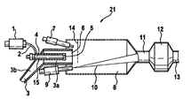
- FIG. 1 in this case shows a burner construction according to the invention for carrying out the method according to the invention.
- FIG. 1 shows a device for generating a resource, especially a reducing agent for exhaust aftertreatment of motor vehicles equipped with an internal combustion engine.
- the reducing agent can be removed at the outlet 13 of the device and fed to an exhaust pipe of the internal combustion engine.
- the device 21 has a combustion chamber 8, in which an air supply line 3 opens.
- the air feed line 3 has a swirl chamber 3a protruding into the combustion chamber 8 and a connecting line 3b adjoining the combustion chamber on the side of the swirl chamber 3a facing away from the combustion chamber.
- the connecting line 3b is in a non-zero angle relative to the swirl chamber 3 a, so that air supplied via the connecting line 3 b when exiting the swirl chamber into the combustion chamber 8 is provided with a swirl, thus forming an inhomogeneous air flow.
- a preheating element is arranged in the form of a glow plug 4 formed as an electric heater.
- the glow plug 4 extends along a longitudinal axis of the swirl chamber 3a, with one end of the elongated glow plug oriented toward the combustion chamber, but within the swirl chamber 3a.
- the combustion chamber 8 facing away from the end of the glow plug 4 projects, sealed against the air supply line 3, out of the air supply line 3, wherein the glow plug is surrounded to form a particular fillable with a liquid annular gap 15 of a shape of the glow plug adapted housing.
- This annular gap 15 is dosed with fuel via a fuel supply line 2 connected to an injection valve 1 acted upon.
- the annular gap 15 opens to an outlet opening 5, which establishes a connection to the combustion chamber 8 via an interior region of the swirl chamber 3a facing the combustion chamber.
- the outlet opening 6 of the swirl chamber adjacent to an electric spark plug 7 is arranged.
- Both the spark plug 7 and the outlet opening 6 of the swirl chamber are aligned with a flame stabilizing means in the form of a metal net 14, wherein the metal net 14 spaced from the outlet opening 6 and also spaced from the spark plug 7 in the combustion chamber 8 is arranged.
- a flame stabilizing means in the form of a metal net 14, wherein the metal net 14 spaced from the outlet opening 6 and also spaced from the spark plug 7 in the combustion chamber 8 is arranged.
- On the outlet opening 6 of the swirl chamber and the spark plug 7 opposite side of the combustion chamber 8 is the outlet opening 11 of the combustion chamber.
- a second injection valve 9 protrudes with its opening on the side into the combustion chamber 8, on which also the spark plug 7 and the swirl chamber 3a projects into the combustion chamber.
- the injection valve 9 is aligned with the outlet opening 11 of the combustion chamber, so that when the injection valve 9 is open, a fuel spray 10 aimed at the outlet opening 11 can be formed.
- a catalyst device 12 in the form of a partial oxidation reforming catalyst whose
- hydrogen and / or carbon monoxide can be used as a reducing agent in the regeneration of NO x storage catalysts.
- Synthesis gas of hydrogen or carbon monoxide or a mixture of both leads to a more efficient reduction at lower catalyst temperatures compared to the use of hydrocarbons.
- the regeneration of a NO x - storage catalyst can be shifted to temperatures in the range of 200 degrees Celsius to 150 degrees Celsius.
- the synthesis gas by a so-called reforming process (“CPOX”, abbreviation for the English term “catalytic partial oxidation”) of liquid Hydrocarbons, in particular gasoline and diesel fuel, are generated directly in the vehicle by means of the device according to the invention.
- CPOX reforming process
- the system with integrated burner is characterized by short start times in the range of less than ten seconds and a high degree of dynamics in the demand-oriented provision of the hydrogen / carbon monoxide mixture.
- the valve is preferably operated at clock frequencies above 30 hertz.
- the metered fuel in this case flows through the tube designed as a fuel line 2 into the annular gap 15 and evaporates on the hot surface of the glow plug. Due to the small cross-sectional area of the tube 2, the injection valve 1 is thermally decoupled from the hot evaporator region.
- the pulsation of the required combustion air takes place via the air supply line 3, which can be acted upon by an unspecified electromagnetically actuated valve, a throttle or other suitable method with air, the air from a pressure accumulator depending on the exhaust back pressure at about 0.2 (at idle) to 1.5 bar (at full load, especially when already filled diesel particulate filter) removed can be.
- the filling of the air reservoir takes place via a compressor or the turbocharger present in the vehicle, because due to the comparatively high exhaust back pressures of up to 500mbar in the vehicle conventional blowers are not sufficient to provide the necessary form for dosing the air ,
- the burner air is supplied tangentially to the evaporator or burner via the swirl chamber 3a.
- the imprinted swirl also promotes burnup and stabilization of the flame within the combustion chamber 8 through the formation of recirculation zones.
- two ignition electrodes are used
- the ignition is only required when starting the burner, because the flame is self-sustaining. This is possible because the combustion chamber 8 is in a defined state with defined gas flows, ie not within an exhaust pipe of the motor vehicle, in which different gas pressures and different gas compositions can not ensure stable flame operation.
- the air swirl promotes good mixing and thus efficient combustion.
- the flame holder 14 or the metal net 14 stabilizes a once excited combustion of the fuel supplied via the injection valve 1 and vaporized by means of the glow plug 4.
- lean stoichiometric conditions prevail (lambda value between 1.1 and 1.2), so that the fuel supplied via the injection valve 1 can be completely burned.
- combustion sales are achieved in the combustion of the fuel from the injection valve 1, which leads to a heat output in the range between 0.5 and 3 kilowatts.
- the fuel is added as starting material for the reforming catalyst 12 via the second low-pressure injection valve 9.
- the high momentum of the fuel exiting from the nozzle opening of the injection valve 9 can be fed through the combustion chamber 8 to the catalytic reforming process in the catalytic converter 12 without limiting the stability of the burner.
- the liquid introduced fuel from the injection valve 9 in the hot burner exhaust gas is rapidly and completely evaporated, so that damage to the catalyst 12 can be avoided by impact of fuel droplets.
- the on the second injection valve. 9 supplied fuel is completely evaporated in the combustion chamber 8, but at most partially oxidized. Using such a partial oxidation reforming catalyst produces much hydrogen and carbon monoxide.
- a cracking catalyst can also be used.
- a cracking catalyst chops long-chain hydrocarbon molecules into shorter molecular chains, which can also be used as a reducing agent for the regeneration of NO x - storage catalysts, but with the disadvantage of partial sooting of downstream exhaust devices.
- equipment leaking via the outlet 13 can also be used in mobile fuel cell systems, in auxiliary heaters for passenger cars such as auxiliary heaters and for emission reduction during vehicle cold start.
- a second air feed may be provided in the region of the outlet opening 11 of the combustion chamber or in a region between the combustion chamber 8 and the catalyst device 12 in order to supply oxygen for the partial oxidation of the fuel metered by means of the injection valve 9.
- the device according to the invention can therefore contain an ignition element (7), in particular a spark plug or two ignition electrodes, wherein the ignition element is optionally arranged in the region of the mouth of the air supply line into the combustion chamber.
- the starting material supply unit (9) is arranged in the region of the mouth of the air supply line into the combustion chamber, so that via the feedstock supplied raw material can mix with substances that from the excitation of combustion of the feedstock via the preheating supplied via the Ignition element result.
- the combustion chamber has an outlet opening (11), wherein the outlet opening is arranged on the side of the combustion chamber opposite the starting material feed unit (9).
- the outlet opening (11) can be connected to the catalyst device, wherein the outlet (13) of the catalyst device can be connected to an exhaust gas line of an internal combustion engine.
- the internal combustion engine belongs to a motor vehicle and that the starting material is fuel with which the internal combustion engine can be operated.
- the catalyst device (12) has a catalytic converter for catalytic partial oxidation.
- the device is set up for the post-motor introduction of the operating medium into an exhaust gas line of the motor vehicle.
Landscapes
- Engineering & Computer Science (AREA)
- Chemical & Material Sciences (AREA)
- Chemical Kinetics & Catalysis (AREA)
- Combustion & Propulsion (AREA)
- Mechanical Engineering (AREA)
- General Engineering & Computer Science (AREA)
- Health & Medical Sciences (AREA)
- Toxicology (AREA)
- Exhaust Gas After Treatment (AREA)
- Control Of Electric Motors In General (AREA)
- Hybrid Electric Vehicles (AREA)
Description
- Die Erfindung geht aus von einer Vorrichtung bzw. einem Verfahren nach der Gattung der unabhängigen Ansprüche. Die Abgasreinigung bei Otto- und Dieselmotoren gewinnt immer mehr an Bedeutung. Im überstöchiometrischen Abgas, also beim Magerbetrieb eines Ottomotors bzw. beim Betrieb eines Dieselmotors, können die bei der Verbrennung entstehenden Stickoxide aufgrund des Sauerstoffüberschusses nicht ausreichend abgebaut werden. Daher wird auch bei Dieselfahrzeugen eine weitergehende Abgasnachbehandlung bezüglich Partikel- und NOx - Emissionen erforderlich. Zur Reduzierung der NOx - Emissionen bieten sich hierbei die NOx - Speicherkatalysatoren an. Diese speichern auch unter überstöchiometrischen Bedingungen Stickoxide ein. Mit zunehmender Menge an eingespeicherten Stickoxiden nimmt die Speicherfähigkeit ab, sodass der Speicherkatalysator in regelmäßigen Abständen wieder ausgeräumt bzw. regeneriert werden muss. Dies ist nur in einer reduzierenden Umgebung möglich, das heißt es müssen zunächst fette Abgasbedingungen (Lambdawert < 1) eingestellt werden. Aus der
DE 100 62 956 ist bereits bekannt, außerhalb der Abgasleitung der Brennkraftmaschine eines Kraftfahrzeugs ein Reduktionsmittel an Bord des Kraftfahrzeugs zu Erzeugen und nachmotorisch dem Abgas vor Eintritt in einen DeNOx - Katalysator zuzuführen. - Die erfindungsgemäße Vorrichtung bzw. das erfindungsgemäße Verfahren zur Erzeugung eines Betriebsmittels haben demgegenüber den Vorteil einer bedarfsgerechten und dynamischen Bereitstellung eines Betriebsmittels, insbesondere eines Synthesegases, bei kurzen Startzeiten und passgenauer Ansprechbarkeit. Im Vergleich zur Menge an Betriebsmittel, die regelmäßig erzeugt wird, ist das Nachlaufvolumen klein, sodass neben einer bedarfsgerechten Bereitstellung innerhalb kurzer Zeiten ungenaue Dosierungen und somit überhöhter Betriebsmittelverbrauch bzw. Umweltbelastungen vermieden werden. Das erfindungsgemäße System ist in vielfältiger Weise einsetzbar, insbesondere zur Bereitstellung von Synthesegas mit hohen Anteilen von Wasserstoff und Kohlenmonoxid zur Regenerierung von NOx - Speicherkatalysatoren. Darüber hinaus kann das System auch zur Regenerierung und Desulfatisierung von Rußpartikelfiltern eingesetzt werden. Neben diesen Anwendungen bei der dieselmotorischen Abgasnachbehandlung lässt sich ein mittels der erfindungsgemäßen Vorrichtung bereitgestelltes Synthesegas auch für ein verbessertes Motorverhalten bezüglich Kaltstart und Mischbetrieb einsetzen, also dem Kraftstoff zusetzen, den die Brennkraftmaschine zum Antrieb des Kraftfahrzeugs verwendet. Darüber hinaus kann ein mittels der erfindungsgemäßen Vorrichtung erzeugter Wasserstoff auch in mobilen Brennstoffzellensystemen als Brennstoff dienen. Über eine separate Ausgangsstoffzuführungseinheit zugeführter Ausgangsstoff wird durch das kleine Volumen an erhitztem und dann verbrannten Ausgangsstoffes, insbesondere durch die entstehenden Verbrennungsprodukte bzw. Verbrennungsgase gut erwärmt bzw. erhitzt und gleichzeitig mit der zugeführten Luft durchmischt, sodass eine warme bzw. heiße Ausgangsstoff- Luft- Mischung in der Brennkammer erzeugt wird, die in effizienter Weise beispielsweise in einem Reformerkatalysator zur partiellen Oxidation zur Erzeugung eines Reduktionsmittels verwendet werden kann, der in einem weiteren Schritt in der Abgasleitung einer Brennkraftmaschine zur Regenerierung eines NOx - Speicherkatalysators genutzt werden kann.
- Durch die in den abhängigen Ansprüchen und in der Beschreibung aufgeführten Maßnahmen sind vorteilhafte Weiterbildungen und Verbesserung der in den unabhängigen Ansprüchen angegebenen Vorrichtungen bzw. Verfahren möglich. Besonders vorteilhaft ist, dass eine Brennkammer außerhalb der Abgasleitung des Kraftfahrzeugs angeordnet ist, sodass definierte Luftbedingungen in der Kammer eingestellt werden können.
- Des weiteren ist es vorteilhaft, die Luftzuleitung derart auszuführen, dass der Luftstrom mit einem Drall beaufschlagt wird. Durch ein schräg bzw. im rechten Winkel zur Mündung der Luftzuleitung in der Brennkammer angeordnetes Luftzufuhrsystem wird eine schnelle und gute Durchmischung des erhitzten Ausgangsstoffs mit zugeführter Luft erzielt.
- In vorteilhafter Weise wird ein Vorheizelement als Glühstiftkerze ausgebildet, die als Standardbauteil bereits vorhanden ist und in effizienter Weise einen relativ kleinen mit Ausgangsstoff bespülbaren Raum, insbesondere Ringspalt, bereitstellt, sodass erstens eine schnelle Erhitzung kleiner Volumina erfolgen kann und zweitens ein Nachlaufvolumen beim Ausschalten des Systems in Relation zum insgesamt mittels der Vorrichtung umgesetzten Ausgangsstoff kleingehalten werden kann.
- Mittels eines Zündelements, insbesondere einer Zündkerze, kann in vorteilhafter Weise der erhitzte Ausgangsstoff, der bereits mit zugeführter Luft vermischt ist, entzündet werden in einer Art und Weise, die eine sich selbst erhaltende Verbrennung gewährleistet.
- Weitere Vorteile ergeben sich aus den weiteren in den weiteren abhängigen Ansprüchen bzw. in der Beschreibung genannten Merkmalen.
- Zeichnung Ein Ausführungsbeispiel der Erfindung ist in der Zeichnung dargestellt und in der nachfolgenden Beschreibung näher erläutert.
Figur 1 zeigt hierbei eine erfindungsgemäße Brennerkonstruktion zur Durchführung des erfindungsgemäßen Verfahrens. - Beschreibung der Ausführungsbeispiele
Figur 1 zeigt eine Vorrichtung zur Erzeugung eines Betriebsmittels, speziell eines Reduktionsmittels zur Abgasnachbehandlung von mit einer Brennkraftmaschine ausgestatteten Kraftfahrzeugen. Das Reduktionsmittel kann am Ausgang 13 der Vorrichtung entnommen und einer Abgasleitung der Brennkraftmaschine zugeführt werden. Die Vorrichtung 21 weist eine Brennkammer 8 auf, in die eine Luftzuleitung 3 mündet. Die Luftzuleitung 3 weist dabei eine in die Brennkammer 8 hineinragende Drallkammer 3a und eine sich auf der der Brennkammer abgewandten Seite der Drallkammer 3a anschließenden Anschlussleitung 3b auf. Die Anschlussleitung 3b ist in einem von Null verschiedenen Winkel relativ zur Drallkammer 3a angeordnet, sodass über die Anschlussleitung 3b zugeführte Luft beim Austreten aus der Drallkammer hinein in die Brennkammer 8 mit einem Drall versehen ist, also eine inhomogene Luftströmung ausbildet. Innerhalb der Drallkammer 3a ist ein Vorheizelement in Form einer als Glühstiftkerze 4 ausgebildeten elektrischen Heizung angeordnet. Die Glühstiftkerze 4 erstreckt sich entlang einer Längsachse der Drallkammer 3a, wobei das eine Ende der länglichen Glühstiftkerze zur Brennkammer hin orientiert ist, sich jedoch innerhalb der Drallkammer 3a befindet. Das der Brennkammer 8 abgewandte Ende der Glühstiftkerze 4 ragt, gegenüber der Luftzuleitung 3 abgedichtet, aus der Luftzuleitung 3 heraus, wobei die Glühstiftkerze zur Ausbildung eines insbesondere mit einer Flüssigkeit befüllbaren Ringspalts 15 von einem der Form der Glühstiftkerze angepassten Gehäuse umgeben ist. Dieser Ringspalt 15 ist über ein mit einer Kraftstoffzuleitung 2 verbundenes Einspritzventil 1 dosiert mit Kraftstoff beaufschlagbar. Auf der der Brennkammer zugewandten Seite der Glühstiftkerze öffnet sich der Ringspalt 15 zu einer Austrittsöffnung 5, die über einen der Brennkammer zugewandten Innenbereich der Drallkammer 3a eine Verbindung zur Brennkammer 8 herstellt. Der Austrittsöffnung 6 der Drallkammer benachbart ist eine elektrische Zündkerze 7 angeordnet. Sowohl die Zündkerze 7 als auch die Austrittsöffnung 6 der Drallkammer sind auf ein Flammenstabilisierungsmittel in Form eines Metallnetzes 14 ausgerichtet, wobei das Metallnetz 14 beabstandet zur Austrittsöffnung 6 und auch beabstandet zur Zündkerze 7 in der Brennkammer 8 angeordnet ist. Auf der der Austrittsöffnung 6 der Drallkammer und der Zündkerze 7 gegenüberliegenden Seite der Brennkammer 8 befindet sich die Austrittsöffnung 11 der Brennkammer. Ein zweites Einspritzventil 9 ragt mit seiner Öffnung auf der Seite in die Brennkammer 8 hinein, auf der auch die Zündkerze 7 und die Drallkammer 3a in die Brennkammer hineinragt. Das Einspritzventil 9 ist dabei auf die Austrittsöffnung 11 der Brennkammer hin ausgerichtet, sodass bei geöffnetem Einspritzventil 9 sich ein auf die Austrittsöffnung 11 zielender Kraftstoffspray 10 ausbilden kann. Stromabwärts der Austrittsöffnung 11 der Brennkammer schließt sich eine Katalysatoreinrichtung 12 in Form eines Reformerkatalysators zur partiellen Oxidation an, dessen Ausgang 13 wiederum das gewünschte Reduktionsmittel entnommen werden kann. - Neben Kohlenwasserstoffen, also insbesondere Otto- bzw. Dieselkraftstoff, können auch Wasserstoff und / oder Kohlenmonoxid als Reduktionsmittel bei der Regeneration von NOx -Speicherkatalysatoren eingesetzt werden. Die Verwendung eines solchen Synthesegases aus Wasserstoff oder Kohlenmonoxid bzw. aus einer Mischung von beidem führt im Vergleich zur Verwendung von Kohlenwasserstoffen zu einer eflizienteren Reduktion bei niedrigeren Katalysatortemperaturen. Dabei kann die Regeneration eines NOx - Speicherkatalysators zu Temperaturen im Bereich von 200 Grad Celsius bis 150 Grad Celsius verschoben werden. Um das Betanken des Kraftfahrzeugs mit Wasserstoff bzw. Kohlenmonoxid aus weiteren Betriebsmitteln sowie das Mitführen der notwendigen Druckgas bzw. Flüssigspeicher zu vermeiden, kann das Synthesegas durch einen sogenannten Reformierungsprozess ("CPOX", Abkürzung für den englischen Ausdruck "Catalytic Partial Oxidation") aus flüssigen Kohlenwasserstoffen, insbesondere Otto- und Dieselkraftstoff, direkt im Fahrzeug mittels der erfindungsgemäßen Vorrichtung erzeugt werden. Das System mit integriertem Brenner zeichnet sich dabei durch kurze Startzeiten im Bereich unterhalb von zehn Sekunden und einer hohen Dynamik bei der bedarfsgerechten Bereitstellung des Wasserstoff-/Kohlenmonoxid- Gemischs aus. Bei dem katalytisch unterstützten Reformierungsprozess werden Luft und Kraftstoff bei unterstöchiometrischen Bedingungen, also bei einem Lambda-Wert im Bereich insbesondere zwischen 0,3 und 0,45, zu einem wasserstoff- und kohlenmonoxidreichen Synthesegas umgesetzt. Hierzu muss das in den Reformerkatalysator 12 zur partiellen Oxidation eintretende Eduktgemisch bezüglich Temperatur und homogener Durchmischung aufbereitet werden. Der aus einem Fahrzeugtank über eine nicht näher dargestellte konventionelle Elektrokraftstoffpumpe und ein Druckhalteventil bei ca. 2 bis 3bar bereitgestellte Kraftstoff wird bedarfsgerecht über das Niederdruckeinspritzventil 1 dem Brenner zugeführt. Um eine stabile und emissionsarme Verbrennung zu erreichen, wird der Kraftstoff im Brenner mittels der Glühstiftkerze 4 verdampft. Um Pulsationen im Brenner, die zum Verlöschen der Flamme und zu erhöhten Emissionen führen können, zu vermeiden, wird das Ventil vorzugsweise bei Taktfrequenzen oberhalb von 30 Hertz betrieben. Der dosierte Kraftstoff fließt hierbei über die als Röhrchen ausgeführte Kraftstoffleitung 2 in den Ringspalt 15 und verdampft an der heißen Oberfläche der Glühstiftkerze. Durch die geringe Querschnittsfläche des Röhrchens 2 wird das Einspritzventil 1 vom heißen Verdampferbereich thermisch entkoppelt. Die Pulsierung der benötigten Verbrennungsluft erfolgt über die Luftzuleitung 3, die über ein nicht näher dargestelltes elektromagnetisch betätigbares Ventil, eine Drossel oder eine andere geeignete Methode mit Luft beaufschlagt werden kann, wobei die Luft aus einem Druckspeicher in Abhängigkeit vom Abgasgegendruck bei ca. 0,2 (bei Leerlauf) bis 1,5 bar (bei Volllast, insbesondere bei bereits gefülltem Dieselpartikelfilter) entnommen werden kann. Die Befüllung des Luftspeichers, der nicht näher dargestellt ist, erfolgt dabei über einen Kompressor oder den im Fahrzeug vorhandenen Turbolader, denn aufgrund der vergleichsweise hohen Abgasgegendrücke von bis zu 500mbar im Fahrzeug reichen konventionelle Gebläse nicht aus, um den nötigen Vordruck zur Dosierung der Luft bereitzustellen. Die Brennerluft wird dem Verdampfer bzw. Brenner über die Drallkammer 3a tangential zugeführt. Dadurch wird die Vermischung der Luft mit dem verdampften Brennstoff (Kraftstoff als Ausgangsstoff) unterstützt. Der aufgeprägte Drall fördert durch die Ausbildung von Rezirkulationsgebieten zudem den Ausbrand und die Stabilisierung der Flamme innerhalb der Brennkammer 8. Zur Zündung des in die Brennkammer 8 eintretenden Gemischs von verdampftem Kraftstoff, der über das Einspritzventil 1 zugeführt wird, und der Luft dienen zwei Zündelektroden bzw. die konventionelle Zündkerze 7, mittels denen bzw. mittels der über eine elektrische Hochspannung ein Lichtbogen erzeugt wird. Die Zündung ist hierbei nur beim Start des Brenners erforderlich, weil die Flamme sich selbst erhält. Dies ist möglich, weil sich die Brennkammer 8 in einem definiertem Zustand mit definierten Gasflüssen befindet, also nicht innerhalb einer Abgasleitung des Kraftfahrzeugs, bei der unterschiedliche Gasdrücke und unterschiedliche Gaszusammensetzungen keinen stabilen Flammenbetrieb gewährleisten können. Darüber hinaus unterstützt der Luftdrall eine gute Vermischung und damit eine effiziente Verbrennung. Darüber hinaus stabilisiert der Flammenhalter 14 bzw. das Metallnetz 14 eine einmal angeregte Verbrennung des über das Einspritzventil 1 zugeführten und mittels der Glühstiftkerze 4 verdampften Kraftstoffs. Im Bereich der Austrittsöffnung 6 der Drallkammer und der Zündkerze 7 herrschen überstöchiometrische Bedingungen (Lambda-Wert zwischen 1,1 und 1,2) vor, sodass der über das Einspritzventil 1 zugeführte Kraftstoff vollständig verbrannt werden kann. Hierbei werden im Brennerbetrieb im Bereich der Zündkerze bei der Verbrennung des Kraftstoffs aus dem Einspritzventil 1 Verbrennungsumsätze erzielt, die zu einer Wärmeleistung im Bereich zwischen 0,5 und 3Kilowatt führen. Im Anschluss an die Verbrennung erfolgt eine Zugabe des Kraftstoffs als Ausgangsstoff für den Reformerkatalysator 12 über das zweite Niederdruckeinspritzventil 9. Durch den hohen Impuls des aus der Düsenöffnung des Einspritzventils 9 austretenden Kraftstoffs kann dieser durch die Brennkammer 8 hindurch dem katalytischen Reformierungsprozess im Katalysator 12 zugeführt werden, ohne die Stabilität des Brenners einzuschränken. Dabei wird der flüssig eingebrachte Kraftstoff aus dem Einspritzventil 9 im heißen Brennerabgas schnell und vollständig verdampft, sodass eine Schädigung des Katalysators 12 durch Auflreffen von Kraftstofftropfen vermieden werden kann. Der über das zweite Einspritzventil 9 zugeführte Kraftstoff wird in der Brennkammer 8 vollständig verdampft, aber allenfalls partiell oxidiert. Bei Verwendung eines derartigen Reformerkatalysators zur partiellen Oxidation entsteht viel Wasserstoff und Kohlenmonoxid. Diese Moleküle sind trotz ihres gegenüber flüssigen Kohlenwasserstoffen geringeren Reduktionspotentials zu bevorzugen, da sie aufgrund ihrer geringeren Größe im Vergleich zu langkettigen Kohlenwasserstoffen reaktiver sind und den Vorteil bieten, einen zu regenerierenden NOx -Speicherkatalysator nicht zu verrußen.
- In einer alternativen Ausführungsform kann jedoch auch ein Crackkatalysator eingesetzt werden. Ein Crackkatalysator zerhackt langkettige Kohlenwasserstoffmoleküle in kürzere Molekülketten, die ebenfalls als Reduktionsmittel zur Regenerierung von NOx - Speicherkatalysatoren Verwendung finden können, allerdings mit dem Nachteil einer teilweisen Verrußung nachgeordneter Abgaseinrichtungen. Neben der Regenerierung von NOx -Speicherkatalysatoren oder von Dieselpartikelfiltern kann über den Ausgang 13 austretendes Betriebsmittel auch in mobilen Brennstoffzellensystemen, in Zuheizgeräten für Personenkraftwagen wie Standheizungen und zur Emissionsminderung beim Fahrzeugkaltstart verwendet werden. Durch vormotorische Zumischung von Wasserstoff und Kohlenmonoxid zum flüssigen Kraftstoff kann hierbei der Verbrennungsprozess der Brennkraftmaschine positiv beeinflusst werden. Es entstehen weniger Rohemissionen, die der noch kalte Abgaskatalysator nicht umsetzen kann. Hierfür müssen die Startzeiten des Systems sehr klein sein, da ein Großteil der Emissionen beim Start zirka in den ersten 30 Sekunden entsteht. In einer weiteren alternativen Ausführungsform kann im Bereich der Austrittsöffnung 11 der Brennkammer bzw. in einem Bereich zwischen der Brennkammer 8 und der Katalysatoreinrichtung 12 eine zweite Luftzuführung vorgesehen sein, um Sauerstoff für die partielle Oxidation des mittels des Einspritzventils 9 dosierten Kraftstoffs zuzuführen.
- Die erfindungsgemäße Vorrichtung kann also ein Zündelement (7), insbesondere eine Zündkerze oder zwei Zündelektroden, enthalten, wobei das Zündelement wahlweise im Bereich der Mündung der Luftzuleitung in die Brennkammer angeordnet ist.
- Es kann vorgesehen sein, dass die Ausgangsstoffzuführungseinheit (9) im Bereich der Mündung der Luftzuleitung in die Brennkammer angeordnet ist, so dass über die Ausgangsstoffzuführungseinheit zugeführter Ausgangsstoff sich mit Stoffen vermischen kann, die aus der Anregung einer Verbrennung des über das Vorheizelement zugeführten Ausgangsstoffs über das Zündelement resultieren.
- Es kann ferner vorgesehen sein, dass die Brennkammer eine Ausgangsöffnung (11) aufweist, wobei die Ausgangsöffnung auf der der Ausgangsstoffzuführungseinheit (9) gegenüberliegenden Seite der Brennkammer angeordnet ist. Wahlweise kann hierbei die Ausgangsöffnung (11) mit der Katalysatoreinrichtung verbunden sein, wobei der Ausgang (13) der Katalysatoreinrichtung mit einer Abgasleitung einer Brennkraftmaschine verbindbar ist.
- Es kann ferner vorgesehen sein, dass die Brennkraftmaschine zu einem Kraftfahrzeug gehört und dass der Ausgangsstoff Kraftstoff ist, mit dem die Brennkraftmaschine betrieben werden kann.
- Es kann ferner vorgesehen sein, dass die Katalysatoreinrichtung (12) einen Reformerkatalysator zur katalytischen partiellen Oxidation aufweist.
- Es kann ferner vorgesehen sein, dass die Vorrichtung eingerichtet ist zur nachmotorischen Einbringung des Betriebsmittels in eine Abgasleitung des Kraftfahrzeugs.
Claims (10)
- Vorrichtung zur Erzeugung eines Betriebsmittels für ein Kraftfahrzeug zur Abgasnachbehandlung des Kraftfahrzeugs, aus einem Ausgangsstoff, mit einer Heizungseinrichtung, mit einem Mittel zur Erzeugung eines Ausgangsstoff-Luft-Gemischs und mit einer Katalysatoreinrichtung, wobei das erwärmte Ausgangsstoff-Luft-Gemisch der Katalysatoreinrichtung (12) zugeführt wird, so dass einem Ausgang (13) der Katalysatoreinrichtung das Betriebsmittel entnehmbar ist, dadurch gekennzeichnet,- dass die Speisung der Heizungseinrichtung mit dem Ausgangsstoff mittels eines vorgeschalteten ersten Einspritzventils (1) erfolgt,- dass die Heizungseinrichtung ein Vorheizelement (4) umfasst, wobei das Vorheizelement in eine Luftzuleitung (3) integriert ist, so dass ein Teil des Ausgangsstoffs mittels des Vorheizelements in die gasförmige Phase überführt und nach Verlassen des Vorheizelements von einem Luftstrom erfasst werden kann,- wobei der Luftstrom in eine der Katalysatoreinrichtung vorgeordnete, das Mittel zur Erzeugung des Ausgangsstoffs-Luft-Gemischs bildende Kammer (8) mündet,- wobei die Kammer (8) als Brennkammer zur zumindest teilweisen Verbrennung von Ausgangstoff eingerichtet ist und- eine Ausgangsstoffzuführungseinheit (9) in die Brennkammer mündet.
- Vorrichtung nach Anspruch 1, dadurch gekennzeichnet, dass die Kammer (8) außerhalb einer Abgasleitung des Kraftfahrzeugs angeordnet ist.
- Vorrichtung nach Anspruch 1 oder 2, dadurch gekennzeichnet, dass die Luftzuleitung (3) eingerichtet ist zur Beaufschlagung des Luftstroms mit einem Drall.
- Vorrichtung nach einem der vorhergehenden Ansprüche, dadurch gekennzeichnet, dass die Luftzuleitung eingerichtet ist zur Beaufschlagung mit Druckluft, insbesondere mit Druckluft in einem Druckbereich von zirka 0,2 bis 1,5 bar.
- Vorrichtung nach Anspruch 4, dadurch gekennzeichnet, dass die Druckluft komprimierte Umgebungsluft und/oder von einer Abgasleitung des Kraftfahrzeugs abgezweigtes komprimiertes Abgas ist.
- Vorrichtung nach einem der vorhergehenden Ansprüche, dadurch gekennzeichnet, dass das Vorheizelement eine Glühstiftkerze aufweist.
- Vorrichtung nach Anspruch 6, dadurch gekennzeichnet, dass um die Glühstiftkerze herum ein Ringspalt (15) gebildet ist zur Umspülung der Glühstiftkerze mit dem Ausgangsstoff.
- Vorrichtung nach einem der vorhergehenden Ansprüche, dadurch gekennzeichnet, dass beabstandet zur Luftzuleitung ein Flammenstabilisierungsmittel (14), insbesondere ein Metallnetz, in der Brennkammer angeordnet ist.
- Vorrichtung nach einem der vorhergehenden Ansprüche, dadurch gekennzeichnet, dass die Ausgangsstoffzuführungseinheit ein zweites Einspritzventil aufweist.
- Verfahren zur Erzeugung eines Betriebsmittels für ein Kraftfahrzeug zur Abgasnachbehandlung des Kraftfahrzeugs, aus einem Ausgangsstoff, bei dem der Ausgangsstoff erwärmt und mit Luft gemischt wird, wobei das erwärmte Ausgangsstoff-Luft-Gemisch einer Katalysatoreinrichtung (12) zugeführt wird, so dass einem Ausgang (13) der Katalysatoreinrichtung das Betriebsmittel entnehmbar ist, dadurch gekennzeichnet, dass die Speisung der Heizungseinrichtung mit dem Ausgangsstoff mittels eines vorgeschalteten ersten Einspritzventils (1) erfolgt, dass ein Teil des Ausgangsstoffs mittels eines Vorheizelements in die gasförmige Phase überführt und nach Verlassen des Vorheizelements von einem Luftstrom erfasst wird, wobei der Luftstrom in eine der Katalysatoreinrichtung vorgeordnete, das Mittel zur Erzeugung des Ausgangsstoffs-Luft-Gemischs bildende Kammer (8) mündet, wobei die Kammer (8) als Brennkammer zur zumindest teilweisen Verbrennung von Ausgangstoff eingerichtet ist und eine Ausgangsstoffzuführungseinheit (9) in die Brennkammer mündet.
Applications Claiming Priority (2)
| Application Number | Priority Date | Filing Date | Title |
|---|---|---|---|
| DE102004051905A DE102004051905A1 (de) | 2004-10-26 | 2004-10-26 | Vorrichtung und Verfahren zur Erzeugung eines Betriebsmittels für ein Kraftfahrzeug |
| PCT/EP2005/054459 WO2006045669A1 (de) | 2004-10-26 | 2005-09-08 | Vorrichtung und verfahren zur erzeugung eines betriebsmittels für ein kraftfahrzeug |
Publications (2)
| Publication Number | Publication Date |
|---|---|
| EP1807612A1 EP1807612A1 (de) | 2007-07-18 |
| EP1807612B1 true EP1807612B1 (de) | 2009-08-19 |
Family
ID=35056910
Family Applications (1)
| Application Number | Title | Priority Date | Filing Date |
|---|---|---|---|
| EP05784557A Expired - Lifetime EP1807612B1 (de) | 2004-10-26 | 2005-09-08 | Vorrichtung und verfahren zur erzeugung eines betriebsmittels für ein kraftfahrzeug |
Country Status (5)
| Country | Link |
|---|---|
| US (1) | US7735315B2 (de) |
| EP (1) | EP1807612B1 (de) |
| AT (1) | ATE440208T1 (de) |
| DE (2) | DE102004051905A1 (de) |
| WO (1) | WO2006045669A1 (de) |
Cited By (1)
| Publication number | Priority date | Publication date | Assignee | Title |
|---|---|---|---|---|
| DE102019133509A1 (de) * | 2019-12-09 | 2021-06-10 | Dr. Ing. H.C. F. Porsche Aktiengesellschaft | Verfahren zum Betreiben einer Abgasanlage und Abgasanlage |
Families Citing this family (20)
| Publication number | Priority date | Publication date | Assignee | Title |
|---|---|---|---|---|
| US8082733B2 (en) * | 2005-11-18 | 2011-12-27 | Borgwarner Inc. | Air handling system with after-treatment |
| US20090178394A1 (en) * | 2008-01-15 | 2009-07-16 | Crane Jr Samuel N | Method and Apparatus for Cleaning Electrodes of a Fuel-Fired Burner of an Emission Abatement Assembly |
| KR101401529B1 (ko) * | 2008-04-23 | 2014-06-17 | 에스케이이노베이션 주식회사 | 배기가스 저감장치 및 그 제어방법 |
| DE102008026477A1 (de) | 2008-06-03 | 2009-12-10 | Deutz Ag | Abgasnachbehandlungssystem für eine selbstzündende Brennkraftmaschine |
| DE102008062479A1 (de) * | 2008-12-16 | 2010-06-17 | Emcon Technologies Germany (Augsburg) Gmbh | Abgasanlage einer Verbrennungskraftmaschine |
| DE102008063515A1 (de) * | 2008-12-18 | 2010-06-24 | Deutz Ag | Verdampfer |
| DE102009023550A1 (de) * | 2009-05-30 | 2010-12-09 | Deutz Ag | Abgasnachbehandlungssystem |
| JP5482065B2 (ja) * | 2009-07-14 | 2014-04-23 | 株式会社Ihi | バーナ装置 |
| DE102009058131B4 (de) * | 2009-12-12 | 2012-07-12 | J. Eberspächer GmbH & Co. KG | Vorrichtung |
| CN102003259A (zh) * | 2010-10-14 | 2011-04-06 | 平原滤清器有限公司 | 一种柴油机微粒捕集器的再生控制器 |
| US9027332B2 (en) | 2013-02-27 | 2015-05-12 | Tenneco Automotive Operating Company Inc. | Ion sensor with decoking heater |
| US9027331B2 (en) | 2013-02-27 | 2015-05-12 | Tenneco Automotive Operating Company Inc. | Exhaust aftertreatment burner with preheated combustion air |
| US8991163B2 (en) * | 2013-02-27 | 2015-03-31 | Tenneco Automotive Operating Company Inc. | Burner with air-assisted fuel nozzle and vaporizing ignition system |
| US8959902B2 (en) | 2013-02-27 | 2015-02-24 | Tenneco Automotive Operating Company Inc. | Exhaust treatment burner and mixer system |
| US9534525B2 (en) | 2015-05-27 | 2017-01-03 | Tenneco Automotive Operating Company Inc. | Mixer assembly for exhaust aftertreatment system |
| US10941685B2 (en) * | 2016-02-24 | 2021-03-09 | Jtsmcdp, Llc | Systems, devices, and methods for regenerating a particulate filter |
| DE102019134345B3 (de) * | 2019-12-13 | 2021-05-12 | Dr. Ing. H.C. F. Porsche Aktiengesellschaft | Verfahren für einen Abgastrakt eines Kraftfahrzeugs |
| DE102020101799B4 (de) | 2020-01-27 | 2025-07-03 | Dr. Ing. H.C. F. Porsche Aktiengesellschaft | Vorrichtung und Verfahren zum Betreiben eines Kraftstoffbrenners |
| CN112393273B (zh) * | 2020-12-04 | 2024-11-15 | 重庆超力高科技股份有限公司 | 预混型燃烧器 |
| DE102022203965A1 (de) * | 2022-04-25 | 2023-10-26 | Robert Bosch Gesellschaft mit beschränkter Haftung | Brenner für ein Abgasnachbehandlungssystem, Abgasnachbehandlungssystem für eine Brennkraftmaschine |
Family Cites Families (12)
| Publication number | Priority date | Publication date | Assignee | Title |
|---|---|---|---|---|
| US4383411A (en) * | 1981-08-10 | 1983-05-17 | General Motors Corporation | Diesel exhaust cleaner with burner vortex chamber |
| FR2548264B1 (fr) * | 1983-06-16 | 1985-12-13 | Renault | Regeneration des filtres a particules, notamment pour moteurs diesel |
| DE3732491A1 (de) | 1987-09-26 | 1989-04-13 | Bosch Gmbh Robert | Zuendbrenner fuer eine vorrichtung zum verbrennen von festkoerperpartikeln im abgas von brennkraftmaschinen |
| US4912920A (en) * | 1989-02-02 | 1990-04-03 | Toa Nenryo Kogyo Kabushiki Kaisha | Ultrasonic burner system for regenerating a filter |
| JPH0571334A (ja) * | 1991-09-13 | 1993-03-23 | Toyota Central Res & Dev Lab Inc | 連続燃焼をおこなう燃焼装置における窒素酸化物低減方法およびその装置 |
| US5320523A (en) * | 1992-08-28 | 1994-06-14 | General Motors Corporation | Burner for heating gas stream |
| US5277025A (en) * | 1992-08-31 | 1994-01-11 | General Motors Corporation | Exhaust burner control |
| DE4315278A1 (de) | 1993-05-07 | 1994-11-10 | Siemens Ag | Verfahren und Einrichtung zur Dosierung eines Reduktionsmittels in ein stickoxidhaltiges Abgas |
| US5722588A (en) * | 1994-04-13 | 1998-03-03 | Nippon Soken Inc. | Combustion heater |
| WO2003091551A1 (en) | 2002-04-24 | 2003-11-06 | Arvin Technologies, Inc. | Apparatus and method for regenerating a particulate filter of an exhaust system of an internal combustion engine |
| EP1369557B1 (de) | 2002-06-07 | 2007-08-15 | ArvinMeritor Emissions Technologies GmbH | Kraftfahrzeug mit einem Diesel-Antriebsmotor mit mittels Kraftstoffdampfeindüsung diskontinuierlich regenerierbarem Abgasreinigungssystem |
| US7032376B1 (en) * | 2003-08-27 | 2006-04-25 | Southwest Research Institute | Diesel fuel burner for diesel emissions control system |
-
2004
- 2004-10-26 DE DE102004051905A patent/DE102004051905A1/de not_active Withdrawn
-
2005
- 2005-09-08 WO PCT/EP2005/054459 patent/WO2006045669A1/de not_active Ceased
- 2005-09-08 DE DE502005007963T patent/DE502005007963D1/de not_active Expired - Lifetime
- 2005-09-08 US US11/577,630 patent/US7735315B2/en not_active Expired - Fee Related
- 2005-09-08 AT AT05784557T patent/ATE440208T1/de not_active IP Right Cessation
- 2005-09-08 EP EP05784557A patent/EP1807612B1/de not_active Expired - Lifetime
Cited By (2)
| Publication number | Priority date | Publication date | Assignee | Title |
|---|---|---|---|---|
| DE102019133509A1 (de) * | 2019-12-09 | 2021-06-10 | Dr. Ing. H.C. F. Porsche Aktiengesellschaft | Verfahren zum Betreiben einer Abgasanlage und Abgasanlage |
| DE102019133509B4 (de) | 2019-12-09 | 2025-03-27 | Dr. Ing. H.C. F. Porsche Aktiengesellschaft | Verfahren zum Betreiben einer Abgasanlage und Abgasanlage |
Also Published As
| Publication number | Publication date |
|---|---|
| EP1807612A1 (de) | 2007-07-18 |
| WO2006045669A1 (de) | 2006-05-04 |
| DE102004051905A1 (de) | 2006-04-27 |
| ATE440208T1 (de) | 2009-09-15 |
| US7735315B2 (en) | 2010-06-15 |
| DE502005007963D1 (de) | 2009-10-01 |
| US20080092532A1 (en) | 2008-04-24 |
Similar Documents
| Publication | Publication Date | Title |
|---|---|---|
| EP1807612A1 (de) | Vorrichtung und verfahren zur erzeugung eines betriebsmittels für ein kraftfahrzeug | |
| EP1915518B1 (de) | Vorrichtung, reaktor und verfahren zur reduktion von stickoxyden im abgasstrom von verbrennungskraftmaschinen | |
| DE102008032253B4 (de) | Selbstzündende Verbrennungskraftmaschine mit Ether-Fumigation der Verbrennungsluft für Fahrzeuge und Verfahren zur Ether-Fumigation der Verbrennungsluft in einer selbstzündenden Verbrennungsmaschine für Fahrzeuge | |
| EP0708230B1 (de) | Einrichtung zum Nachbehandeln von Abgasen einer selbstzündenden Brennkraftmaschine | |
| EP3377815B1 (de) | Verfahren und vorrichtung zur einstellung der zündeigenschaft eines brennstoffs, insbesondere zur senkung des schadstoffausstosses von verbrennungseinrichtungen | |
| EP1244512A1 (de) | Einrichtung und verfahren zur nachbehandlung von abgasen | |
| DE60002566T2 (de) | Katalysatorsysteme | |
| EP2291579B1 (de) | Abgasnachbehandlungssystem für eine selbstzündende brennkraftmaschine | |
| DE102017009607A1 (de) | Zuführungs- und Zündvorrichtung für einen Gasmotor und Verfahren zum Betrieb einer Zuführungs- und Zündvorrichtung für einen Gasmotor | |
| DE102016000761A1 (de) | Emulgiersystem und Emulgierverfahren | |
| DE102006043100A1 (de) | Verfahren zur Reduktionsmittelsteuerung in einer Abgasnachbehandlungsanlage | |
| DE102013210116B3 (de) | Brennkraftmaschine und Verfahren zum Betreiben einer Brennkraftmaschine | |
| DE102019202560A1 (de) | System und verfahren zur abgasnachbehandlung, fahrzeug und verfahren zum betreiben eines fahrzeugs | |
| DE102006043087A1 (de) | Verfahren und Vorrichtung zur Aufheizung eines Reduktionsmittel-Generierungssystems | |
| DE102017211158A1 (de) | Reformingsystem | |
| DE10204073A1 (de) | Abgasanlage und Verfahren zur Regeneration eines Partikelfilters | |
| DE102005017719A1 (de) | Reformeranordnung | |
| CN104179604B (zh) | 使用经部分氧化柴油燃料的推进装置和运行该装置的方法 | |
| WO2008012005A1 (de) | Fremdgezündete brennkraftmaschine für gasförmige kraftstoffe und verfahren zum betrieb einer solchen brennkraftmaschine | |
| EP1961932A1 (de) | Verfahren zur katalytischen Abgaserwärmung | |
| DE102018211890A1 (de) | Verfahren zum Betreiben eines Verbrennungsmotors, Vorrichtung zur Durchführung des Verfahrens sowie Verbrennungsmotor | |
| DE112023001362T5 (de) | Nachbehandlung für ammoniakbetriebene motoren | |
| DE102016012457A1 (de) | Antriebseinrichtung für ein Kraftfahrzeug, Abgasmodul für eine Verbrennungskraftmaschine, sowie Verfahren zum Betreiben einer solchen Antriebseinrichtung | |
| DE102008002469A1 (de) | Verfahren und Vorrichtung zur Abgasreinigung | |
| DE102020122067A1 (de) | Abgasnachbehandlungssystem sowie Verfahren zur Abgasnachbehandlung eines Verbrennungsmotors |
Legal Events
| Date | Code | Title | Description |
|---|---|---|---|
| PUAI | Public reference made under article 153(3) epc to a published international application that has entered the european phase |
Free format text: ORIGINAL CODE: 0009012 |
|
| 17P | Request for examination filed |
Effective date: 20070529 |
|
| AK | Designated contracting states |
Kind code of ref document: A1 Designated state(s): AT BE BG CH CY CZ DE DK EE ES FI FR GB GR HU IE IS IT LI LT LU LV MC NL PL PT RO SE SI SK TR |
|
| 17Q | First examination report despatched |
Effective date: 20070828 |
|
| DAX | Request for extension of the european patent (deleted) | ||
| GRAP | Despatch of communication of intention to grant a patent |
Free format text: ORIGINAL CODE: EPIDOSNIGR1 |
|
| GRAS | Grant fee paid |
Free format text: ORIGINAL CODE: EPIDOSNIGR3 |
|
| GRAA | (expected) grant |
Free format text: ORIGINAL CODE: 0009210 |
|
| AK | Designated contracting states |
Kind code of ref document: B1 Designated state(s): AT BE BG CH CY CZ DE DK EE ES FI FR GB GR HU IE IS IT LI LT LU LV MC NL PL PT RO SE SI SK TR |
|
| REG | Reference to a national code |
Ref country code: GB Ref legal event code: FG4D Free format text: NOT ENGLISH |
|
| REG | Reference to a national code |
Ref country code: CH Ref legal event code: EP |
|
| REG | Reference to a national code |
Ref country code: IE Ref legal event code: FG4D |
|
| REF | Corresponds to: |
Ref document number: 502005007963 Country of ref document: DE Date of ref document: 20091001 Kind code of ref document: P |
|
| LTIE | Lt: invalidation of european patent or patent extension |
Effective date: 20090819 |
|
| PG25 | Lapsed in a contracting state [announced via postgrant information from national office to epo] |
Ref country code: FI Free format text: LAPSE BECAUSE OF FAILURE TO SUBMIT A TRANSLATION OF THE DESCRIPTION OR TO PAY THE FEE WITHIN THE PRESCRIBED TIME-LIMIT Effective date: 20090819 Ref country code: LT Free format text: LAPSE BECAUSE OF FAILURE TO SUBMIT A TRANSLATION OF THE DESCRIPTION OR TO PAY THE FEE WITHIN THE PRESCRIBED TIME-LIMIT Effective date: 20090819 Ref country code: IS Free format text: LAPSE BECAUSE OF FAILURE TO SUBMIT A TRANSLATION OF THE DESCRIPTION OR TO PAY THE FEE WITHIN THE PRESCRIBED TIME-LIMIT Effective date: 20091219 Ref country code: SE Free format text: LAPSE BECAUSE OF FAILURE TO SUBMIT A TRANSLATION OF THE DESCRIPTION OR TO PAY THE FEE WITHIN THE PRESCRIBED TIME-LIMIT Effective date: 20090819 Ref country code: ES Free format text: LAPSE BECAUSE OF FAILURE TO SUBMIT A TRANSLATION OF THE DESCRIPTION OR TO PAY THE FEE WITHIN THE PRESCRIBED TIME-LIMIT Effective date: 20091130 |
|
| NLV1 | Nl: lapsed or annulled due to failure to fulfill the requirements of art. 29p and 29m of the patents act | ||
| PG25 | Lapsed in a contracting state [announced via postgrant information from national office to epo] |
Ref country code: PL Free format text: LAPSE BECAUSE OF FAILURE TO SUBMIT A TRANSLATION OF THE DESCRIPTION OR TO PAY THE FEE WITHIN THE PRESCRIBED TIME-LIMIT Effective date: 20090819 Ref country code: SI Free format text: LAPSE BECAUSE OF FAILURE TO SUBMIT A TRANSLATION OF THE DESCRIPTION OR TO PAY THE FEE WITHIN THE PRESCRIBED TIME-LIMIT Effective date: 20090819 Ref country code: LV Free format text: LAPSE BECAUSE OF FAILURE TO SUBMIT A TRANSLATION OF THE DESCRIPTION OR TO PAY THE FEE WITHIN THE PRESCRIBED TIME-LIMIT Effective date: 20090819 Ref country code: NL Free format text: LAPSE BECAUSE OF FAILURE TO SUBMIT A TRANSLATION OF THE DESCRIPTION OR TO PAY THE FEE WITHIN THE PRESCRIBED TIME-LIMIT Effective date: 20090819 |
|
| REG | Reference to a national code |
Ref country code: IE Ref legal event code: FD4D |
|
| BERE | Be: lapsed |
Owner name: ROBERT BOSCH G.M.B.H. Effective date: 20090930 |
|
| PG25 | Lapsed in a contracting state [announced via postgrant information from national office to epo] |
Ref country code: CY Free format text: LAPSE BECAUSE OF FAILURE TO SUBMIT A TRANSLATION OF THE DESCRIPTION OR TO PAY THE FEE WITHIN THE PRESCRIBED TIME-LIMIT Effective date: 20090819 Ref country code: PT Free format text: LAPSE BECAUSE OF FAILURE TO SUBMIT A TRANSLATION OF THE DESCRIPTION OR TO PAY THE FEE WITHIN THE PRESCRIBED TIME-LIMIT Effective date: 20091221 Ref country code: BG Free format text: LAPSE BECAUSE OF FAILURE TO SUBMIT A TRANSLATION OF THE DESCRIPTION OR TO PAY THE FEE WITHIN THE PRESCRIBED TIME-LIMIT Effective date: 20091119 |
|
| PG25 | Lapsed in a contracting state [announced via postgrant information from national office to epo] |
Ref country code: IE Free format text: LAPSE BECAUSE OF FAILURE TO SUBMIT A TRANSLATION OF THE DESCRIPTION OR TO PAY THE FEE WITHIN THE PRESCRIBED TIME-LIMIT Effective date: 20090819 Ref country code: EE Free format text: LAPSE BECAUSE OF FAILURE TO SUBMIT A TRANSLATION OF THE DESCRIPTION OR TO PAY THE FEE WITHIN THE PRESCRIBED TIME-LIMIT Effective date: 20090819 Ref country code: MC Free format text: LAPSE BECAUSE OF NON-PAYMENT OF DUE FEES Effective date: 20090930 Ref country code: CZ Free format text: LAPSE BECAUSE OF FAILURE TO SUBMIT A TRANSLATION OF THE DESCRIPTION OR TO PAY THE FEE WITHIN THE PRESCRIBED TIME-LIMIT Effective date: 20090819 Ref country code: RO Free format text: LAPSE BECAUSE OF FAILURE TO SUBMIT A TRANSLATION OF THE DESCRIPTION OR TO PAY THE FEE WITHIN THE PRESCRIBED TIME-LIMIT Effective date: 20090819 Ref country code: DK Free format text: LAPSE BECAUSE OF FAILURE TO SUBMIT A TRANSLATION OF THE DESCRIPTION OR TO PAY THE FEE WITHIN THE PRESCRIBED TIME-LIMIT Effective date: 20090819 |
|
| REG | Reference to a national code |
Ref country code: CH Ref legal event code: PL |
|
| PG25 | Lapsed in a contracting state [announced via postgrant information from national office to epo] |
Ref country code: SK Free format text: LAPSE BECAUSE OF FAILURE TO SUBMIT A TRANSLATION OF THE DESCRIPTION OR TO PAY THE FEE WITHIN THE PRESCRIBED TIME-LIMIT Effective date: 20090819 |
|
| PLBE | No opposition filed within time limit |
Free format text: ORIGINAL CODE: 0009261 |
|
| STAA | Information on the status of an ep patent application or granted ep patent |
Free format text: STATUS: NO OPPOSITION FILED WITHIN TIME LIMIT |
|
| 26N | No opposition filed |
Effective date: 20100520 |
|
| GBPC | Gb: european patent ceased through non-payment of renewal fee |
Effective date: 20091119 |
|
| PG25 | Lapsed in a contracting state [announced via postgrant information from national office to epo] |
Ref country code: BE Free format text: LAPSE BECAUSE OF NON-PAYMENT OF DUE FEES Effective date: 20090930 |
|
| PG25 | Lapsed in a contracting state [announced via postgrant information from national office to epo] |
Ref country code: GR Free format text: LAPSE BECAUSE OF FAILURE TO SUBMIT A TRANSLATION OF THE DESCRIPTION OR TO PAY THE FEE WITHIN THE PRESCRIBED TIME-LIMIT Effective date: 20091120 Ref country code: CH Free format text: LAPSE BECAUSE OF NON-PAYMENT OF DUE FEES Effective date: 20090930 Ref country code: LI Free format text: LAPSE BECAUSE OF NON-PAYMENT OF DUE FEES Effective date: 20090930 |
|
| PG25 | Lapsed in a contracting state [announced via postgrant information from national office to epo] |
Ref country code: AT Free format text: LAPSE BECAUSE OF NON-PAYMENT OF DUE FEES Effective date: 20090908 |
|
| PGFP | Annual fee paid to national office [announced via postgrant information from national office to epo] |
Ref country code: IT Payment date: 20100924 Year of fee payment: 6 |
|
| PG25 | Lapsed in a contracting state [announced via postgrant information from national office to epo] |
Ref country code: GB Free format text: LAPSE BECAUSE OF NON-PAYMENT OF DUE FEES Effective date: 20091119 |
|
| PG25 | Lapsed in a contracting state [announced via postgrant information from national office to epo] |
Ref country code: LU Free format text: LAPSE BECAUSE OF NON-PAYMENT OF DUE FEES Effective date: 20090908 |
|
| PG25 | Lapsed in a contracting state [announced via postgrant information from national office to epo] |
Ref country code: HU Free format text: LAPSE BECAUSE OF FAILURE TO SUBMIT A TRANSLATION OF THE DESCRIPTION OR TO PAY THE FEE WITHIN THE PRESCRIBED TIME-LIMIT Effective date: 20100220 |
|
| PG25 | Lapsed in a contracting state [announced via postgrant information from national office to epo] |
Ref country code: TR Free format text: LAPSE BECAUSE OF FAILURE TO SUBMIT A TRANSLATION OF THE DESCRIPTION OR TO PAY THE FEE WITHIN THE PRESCRIBED TIME-LIMIT Effective date: 20090819 |
|
| PG25 | Lapsed in a contracting state [announced via postgrant information from national office to epo] |
Ref country code: IT Free format text: LAPSE BECAUSE OF NON-PAYMENT OF DUE FEES Effective date: 20120908 |
|
| PGFP | Annual fee paid to national office [announced via postgrant information from national office to epo] |
Ref country code: DE Payment date: 20151125 Year of fee payment: 11 |
|
| REG | Reference to a national code |
Ref country code: FR Ref legal event code: PLFP Year of fee payment: 12 |
|
| REG | Reference to a national code |
Ref country code: DE Ref legal event code: R119 Ref document number: 502005007963 Country of ref document: DE |
|
| PG25 | Lapsed in a contracting state [announced via postgrant information from national office to epo] |
Ref country code: DE Free format text: LAPSE BECAUSE OF NON-PAYMENT OF DUE FEES Effective date: 20170401 |
|
| REG | Reference to a national code |
Ref country code: FR Ref legal event code: PLFP Year of fee payment: 13 |
|
| PGFP | Annual fee paid to national office [announced via postgrant information from national office to epo] |
Ref country code: FR Payment date: 20170925 Year of fee payment: 13 |
|
| PG25 | Lapsed in a contracting state [announced via postgrant information from national office to epo] |
Ref country code: FR Free format text: LAPSE BECAUSE OF NON-PAYMENT OF DUE FEES Effective date: 20180930 |