EP1807228B1 - Roller hemming machine - Google Patents
Roller hemming machine Download PDFInfo
- Publication number
- EP1807228B1 EP1807228B1 EP05807732A EP05807732A EP1807228B1 EP 1807228 B1 EP1807228 B1 EP 1807228B1 EP 05807732 A EP05807732 A EP 05807732A EP 05807732 A EP05807732 A EP 05807732A EP 1807228 B1 EP1807228 B1 EP 1807228B1
- Authority
- EP
- European Patent Office
- Prior art keywords
- roller
- hemming
- hold down
- guide surface
- robotic arm
- Prior art date
- Legal status (The legal status is an assumption and is not a legal conclusion. Google has not performed a legal analysis and makes no representation as to the accuracy of the status listed.)
- Expired - Lifetime
Links
Images


Classifications
-
- B—PERFORMING OPERATIONS; TRANSPORTING
- B21—MECHANICAL METAL-WORKING WITHOUT ESSENTIALLY REMOVING MATERIAL; PUNCHING METAL
- B21D—WORKING OR PROCESSING OF SHEET METAL OR METAL TUBES, RODS OR PROFILES WITHOUT ESSENTIALLY REMOVING MATERIAL; PUNCHING METAL
- B21D39/00—Application of procedures in order to connect objects or parts, e.g. coating with sheet metal otherwise than by plating; Tube expanders
- B21D39/02—Application of procedures in order to connect objects or parts, e.g. coating with sheet metal otherwise than by plating; Tube expanders of sheet metal by folding, e.g. connecting edges of a sheet to form a cylinder
- B21D39/021—Application of procedures in order to connect objects or parts, e.g. coating with sheet metal otherwise than by plating; Tube expanders of sheet metal by folding, e.g. connecting edges of a sheet to form a cylinder for panels, e.g. vehicle doors
-
- B—PERFORMING OPERATIONS; TRANSPORTING
- B21—MECHANICAL METAL-WORKING WITHOUT ESSENTIALLY REMOVING MATERIAL; PUNCHING METAL
- B21D—WORKING OR PROCESSING OF SHEET METAL OR METAL TUBES, RODS OR PROFILES WITHOUT ESSENTIALLY REMOVING MATERIAL; PUNCHING METAL
- B21D39/00—Application of procedures in order to connect objects or parts, e.g. coating with sheet metal otherwise than by plating; Tube expanders
- B21D39/02—Application of procedures in order to connect objects or parts, e.g. coating with sheet metal otherwise than by plating; Tube expanders of sheet metal by folding, e.g. connecting edges of a sheet to form a cylinder
- B21D39/021—Application of procedures in order to connect objects or parts, e.g. coating with sheet metal otherwise than by plating; Tube expanders of sheet metal by folding, e.g. connecting edges of a sheet to form a cylinder for panels, e.g. vehicle doors
- B21D39/023—Application of procedures in order to connect objects or parts, e.g. coating with sheet metal otherwise than by plating; Tube expanders of sheet metal by folding, e.g. connecting edges of a sheet to form a cylinder for panels, e.g. vehicle doors using rollers
-
- Y—GENERAL TAGGING OF NEW TECHNOLOGICAL DEVELOPMENTS; GENERAL TAGGING OF CROSS-SECTIONAL TECHNOLOGIES SPANNING OVER SEVERAL SECTIONS OF THE IPC; TECHNICAL SUBJECTS COVERED BY FORMER USPC CROSS-REFERENCE ART COLLECTIONS [XRACs] AND DIGESTS
- Y10—TECHNICAL SUBJECTS COVERED BY FORMER USPC
- Y10T—TECHNICAL SUBJECTS COVERED BY FORMER US CLASSIFICATION
- Y10T29/00—Metal working
- Y10T29/53—Means to assemble or disassemble
- Y10T29/53709—Overedge assembling means
- Y10T29/53787—Binding or covering
Definitions
- the present invention relates generally to hemming machines for hemming two sheet metal parts together.
- the part to be hemmed typically an inner panel nested within an outer panel, is supported on a nest.
- the nest is then reciprocally driven sequentially against a prehemming tool die set and, thereafter, a final hemming tool die set in order to hem the parts together.
- a guide surface was formed along the outer periphery of the nest on which the part to be hemmed was positioned.
- a hemming head having at least one roller was then mounted to the end of the robotic arm so that the hemming head together with its roller(s) moved in synchronism with the robotic arm.
- one of the rollers In order to perform the prehem, one of the rollers would engage and be guided by the guide surface formed on the nest during the prehemming (and/or final hem) operation. Since the guide surface on the nest can be very accurately manufactured relative to the part to be hemmed, it is possible to achieve accurate prehems with the robotic roller hemmer. Once the accuracy of the prehemming operation is achieved, typically in multiple passes (two to three), the final prehem can be performed, typically in multiple passes.
- a disadvantage of these previously known robotic roller hemmers which utilized a guide surface on the nest to position the hemming head during the hemming operation is that it is fairly expensive to manufacture and tune the guide surface on the nest. Furthermore, in case of wearing or quick geometry adjustment required by production, since the roller guiding track is part of the nest, any adjustment requires direct grinding or rewelding/regrinding of the nest itself.
- a still further disadvantage of the previously known robotic roller hemming machines is that such machines typically utilized a pressurized air cylinder actuator between the robot and the roller head to create the pressure on the hemming rollers.
- air cylinder actuators either are traditional air cylinders which are room consuming, or simple convolution air bladders which vary in pressurization, and thus the force applied to the hemming rollers, as a function of the extension of the air cylinder.
- Such uneven pressure applied by the hemming roller on the part in turn may result in an inconsistent or non-uniform hem on the part.
- a hemming machine according to the preamble of claim 1 is known from JP 2002102957 A .
- JP 2002160031 A discloses a roller hemming head for use with a robot, comprising a base adapted for attachment to the robot, a guide assembly mounted to said base, an elongated piston shaft axially slidably mounted to said slide assembly. Said piston shaft is movable between an extended and a retracted position wherein at least one hemming roller is attached to a free end of said piston shaft.
- a flexible sleeve is connected between the base and the shaft an forms a pressurizable chamber and a source of fluid pressure is fluidly connected to said pressurizable chamber.
- the present invention provides a hemming machine which overcomes all of the above-mentioned disadvantages of the previously known devices.
- the hemming machine of the present invention comprises a nest which is adapted to support the part to be hemmed.
- the part to be hemmed includes an outer panel having an upwardly extending flange around its outer periphery and an inner panel nested within the outer panel flange.
- Such parts include, for example, automotive closure panels such as door panels.
- a hold down is movable between a retracted position in which the hold down is spaced from the part, and an extended position in which the part is sandwiched between the hold down and the nest. In its extended position, the hold down traps both panels of the part to be hemmed between the hold down and the nest and prevents movement of the parts during the hemming operation.
- a guide surface corresponding to the shape of the desired hem is formed around the outer periphery of the hold down.
- a hemming head is mounted to the free end of a conventional robotic arm.
- This hemming head includes a roller hemming assembly mounted to it so that the roller assembly moves in unison with the hemming head.
- the robotic arm is programmed such that at least one of the rollers on the roller hemmer assembly engages the guide surface on the hold down during the prehemming operation.
- the robotic arm together with the hemming head and its attached roller hemmer assembly is used to perform the final hem on the part.
- the guide surface is formed on the hold down, rather than the nest, the guide surface can be relatively inexpensively machined and tuned on the hold down.
- the roller hemming head comprises a base which is attached to the robotic arm, a piston shaft slidably mounted to the base, and the hemming roller head is in turn mounted to the piston shaft.
- a rolling sleeve type diaphragm is disposed around both the piston shaft and the base to form a closed chamber around the linear guiding slide. This chamber is pressurized by an external pressure source, such as a pressurized air source, in order to maintain pressure within the bladder and, consequently, an outward force on the roller hemmer heads relative to the robotic arm.
- a sensor detects the position of the piston shaft to detect whenever the piston shaft is fully extended or fully retracted, both of which would be indicative of a machine failure or error of some sort.
- a preferred embodiment of the hemming machine 10 of the present invention is shown and comprises a nest 12 which is adapted to support a part 14 to be hemmed.
- the part 14 to be hemmed includes an outer sheet metal panel 16 having a flange 18 about its outer periphery, and an inner panel 20 nested within the outer flange 18 of the outer panel 16.
- a hold down 22 is movable relative to the nest 12 between a retracted position, illustrated in phantom line in FIG. 1 , and an extended position, illustrated in solid line in FIG. 1 .
- the hold down 22 In its retracted position, the hold down 22 is spaced from both the nest 12 and the part 14 to be hemmed thus allowing both a finished part 14 to be removed from the nest 12, and a new unhemmed part 14 to be accurately positioned on the nest 12 by retractable "sweepers".
- the hold down 22 in its extended position, the hold down 22 abuts against the inner panel 20 accurately locating it on the part 14 through locating pins, to bring it into reference with the outer panel. Then it sandwiches the part to be hemmed between the hold down 22 and the nest 12.
- the hold down 22, when in its extended position thus prevents movement of the part 14 relative to the nest 12 during the hemming operation.
- a guide surface 56 is formed around the outer periphery of the hold down 22. This guide surface conforms to the shape of the desired prehem passes for the part 14. If two prehem operations are required, the hold down will present two separate tracks located on two separate steps attached to the hold down perimeter.
- the hemming machine 10 further comprises a programmable robot 24 having a robotic arm 26 which is movable, under program control, relative to a base 28 of the robot 24.
- the robot 24, furthermore, may be of any conventional construction and includes a control system 30 which controls the position of a wrist 32 of the robotic arm 26 relative to the base 24.
- a hemming head 40 includes a base 42 which is mounted to the wrist 32 of the robotic arm 26.
- the base 42 includes a linear guide 44 secured to the base 42 by fasteners 45, while an elongated piston shaft 46 is slidably mounted through the guide 44.
- the piston shaft 46 includes at least one, and preferably three equidistantly spaced, longitudinally extending wings or ridges 100 along the outer surface of the piston shaft 46.
- a plurality of roller bearings 48 are then disposed between receiving channels 102 formed in the linear guide 44 and the piston shaft 46 on both sides of each wing 100.
- the roller bearings 48 enable the piston shaft 46 to slide in a pure linear longitudinal direction relative to the base 42 and guide 44 while the coaction between the roller bearings 48 and wings 100 prevents rotation of the piston shaft 46 about its longitudinal axis.
- a roller hemmer assembly 50 is mounted to one end 52 of the piston shaft 46.
- the roller assembly 50 includes at least one, and preferably two rollers 54 and 57.
- the rollers 54 and 57 are illustrated in FIG. 3 as being coaxially rotatably mounted to the piston 46.
- a flexible rolling sleeve type air bladder 58 sealingly connects the base 42 to a piston end cap 60 attached to the piston shaft 46.
- the bladder 58 thus defines an internal closed chamber 62 between the base 42 and the piston 46, which contains and encloses the linear guide 44.
- This chamber 62 is fluidly connected by ports 64, 66 and 68 to a source 70 of pressurized fluid, such as pressurized air. Consequently, in operation, the pressurized fluid from the source 70 pressurizes the bladder chamber 62 and maintains an outward force on the piston end cap 60 to the piston shaft 46, together with its attached roller assembly 50, relative to the base 42 of the hemmer head 40 and thus relative to the free end 32 of the robotic arm 26.
- a sensor disc 110 is attached to the piston shaft 46 at its end opposite from the hemming rollers 54 and 57.
- a position sensor 112 is mounted to the base 42 at a position radially aligned with the disc 110 and generates an output signal representative of the position of the disc 110 and thus representative of the degree of extension or retraction of the piston shaft 46. Consequently, whenever the piston shaft 46 reaches its fully extended or fully retracted position, indicative of an error or equipment malfunction, the sensor 112 generates an output signal to the operator so that the appropriate corrective action may be taken.
- a resilient shock absorber 114 is also preferably attached to the disc 110 to minimize the possibility of damage to the hemming head in the event the piston shaft 46 moves to its fully extended position.
- the part to be hemmed 14 is mounted on the nest 12 and the hold down 22 is moved to its extended position. In doing so, the hold down 22 clamps the part 14 against the nest 12 and prevents movement of the part 20 during the hemming operation.
- the robotic arm 26 is manipulated under program control by the control system 30 so that one roller 54 of the roller hemming head 40 is positioned against one of the tracks of the guide surface 56 formed around the hold down 22.
- the robotic arm 26 manipulates the hemming head 40, and thus the roller assembly 50, such that the guide roller 54 abuts against and follows the hold down guide surface 56.
- the hemming roller 57 engages the flange 18 on the part 14 to be hemmed and performs the prehem of the flange 18 in the desired fashion.
- FIGS. 9-11 all depict the roller 57 used to perform a final hem.
- the hemming head optionally uses the hold down 22 as a guide for the roller 54 during the final hem.
- the robot 24 manipulates the roller assembly 50 around the entire periphery of the part 14 while maintaining the guide roller 54 in abutment with the guide surface 56.
- the nest 12 is swivelly mounted relative to a ground support surface to minimize the necessary extension of the robotic arm 26.
- the robot 24 first performs a prehem pass around about one half of the part 14, the nest 12 is swiveled about 180 degrees, and the robot 24 then completes the remainder of the prehem pass.
- the robotic arm 26, under program control, manipulates the roller assembly such that one of the rollers of the roller assembly 50, e.g. the roller 57, engages the previously prehemmed flange 18 and compresses the flange 18 against the inner panel 20 to complete the hem between the two panels 16 and 20 of the part 14.
- one of the rollers of the roller assembly 50 e.g. the roller 57
- rollers 54 and 57 are illustrated in FIG. 4 as being coaxially mounted to the hemming head 40, it is not necessary that the rollers 54 and 57 be coaxial with each other.
- FIG. 6 an alternate embodiment is illustrated in which the two rollers 54 and 57 are both mounted to the hemming head 40 along parallel, but not coaxial, axes.
- the roller assembly 50 include two or more rollers.
- a single roller 70 may be rotatably mounted to the hemming head 40.
- the roller 70 would be dimensioned so that one end of the roller 70 contacts and is guided by the guide surface 56 on the hold down 22 while the opposite end of the roller 70 engages the flange 18 on the outer panel 16 of the part 14 and performs the hemming operation.
- a primary advantage of the present invention is that, since the sleeve encompasses and contains the slide mechanism for the hemming head, the hemming head is very compact. Furthermore, the use of a rolling sleeve type air bladder ensures that a constant pressure is maintained for the hemming rollers regardless of the extension or retraction of the piston shaft assuming, of course, that the piston shaft is neither fully extended nor fully retracted.
- the hemming head has been described for use with a hold down having a guide surface, it will be understood that the hemming head may be used with hemming machines having a guide surface formed on components other than the hold down, such as the nest.
- the present invention provides a simple and yet highly effective roller hemming machine which utilizes a guide surface on the part hold down to guide the hemming rollers during the prehemming operation.
Landscapes
- Engineering & Computer Science (AREA)
- Mechanical Engineering (AREA)
- Manipulator (AREA)
Abstract
Description
- The present invention relates generally to hemming machines for hemming two sheet metal parts together.
- There are many previously known hemming machines for hemming two sheet metal parts together. Such hemming means are used, inter alia, in the automotive industry for hemming car body panels together.
- In one type of previously known hemming machine, the part to be hemmed, typically an inner panel nested within an outer panel, is supported on a nest. The nest is then reciprocally driven sequentially against a prehemming tool die set and, thereafter, a final hemming tool die set in order to hem the parts together.
- In still a further type of previously known hemming machine, a robotic arm was utilized to move a roller against the part to be hemmed in order to form both the prehem and, thereafter, the final hem. However, in view of deflection of the robotic arm, it has been previously necessary to carefully guide the roller head assembly as it is moved by the robotic arm in order to perform the hem having the required quality finish.
- In one type of previously known robotic roller hemmer, a guide surface was formed along the outer periphery of the nest on which the part to be hemmed was positioned. A hemming head having at least one roller was then mounted to the end of the robotic arm so that the hemming head together with its roller(s) moved in synchronism with the robotic arm.
- In order to perform the prehem, one of the rollers would engage and be guided by the guide surface formed on the nest during the prehemming (and/or final hem) operation. Since the guide surface on the nest can be very accurately manufactured relative to the part to be hemmed, it is possible to achieve accurate prehems with the robotic roller hemmer. Once the accuracy of the prehemming operation is achieved, typically in multiple passes (two to three), the final prehem can be performed, typically in multiple passes.
- A disadvantage of these previously known robotic roller hemmers which utilized a guide surface on the nest to position the hemming head during the hemming operation is that it is fairly expensive to manufacture and tune the guide surface on the nest. Furthermore, in case of wearing or quick geometry adjustment required by production, since the roller guiding track is part of the nest, any adjustment requires direct grinding or rewelding/regrinding of the nest itself.
- A still further disadvantage of the previously known robotic roller hemming machines is that such machines typically utilized a pressurized air cylinder actuator between the robot and the roller head to create the pressure on the hemming rollers. Such air cylinder actuators, however, either are traditional air cylinders which are room consuming, or simple convolution air bladders which vary in pressurization, and thus the force applied to the hemming rollers, as a function of the extension of the air cylinder. Such uneven pressure applied by the hemming roller on the part in turn may result in an inconsistent or non-uniform hem on the part.
- A hemming machine according to the preamble of claim 1 is known from
JP 2002102957 A -
JP 2002160031 A - The present invention provides a hemming machine which overcomes all of the above-mentioned disadvantages of the previously known devices.
- In brief, the hemming machine of the present invention comprises a nest which is adapted to support the part to be hemmed. Typically, the part to be hemmed includes an outer panel having an upwardly extending flange around its outer periphery and an inner panel nested within the outer panel flange. Such parts include, for example, automotive closure panels such as door panels.
- After the part to be hemmed is positioned within the nest, a hold down is movable between a retracted position in which the hold down is spaced from the part, and an extended position in which the part is sandwiched between the hold down and the nest. In its extended position, the hold down traps both panels of the part to be hemmed between the hold down and the nest and prevents movement of the parts during the hemming operation.
- A guide surface corresponding to the shape of the desired hem is formed around the outer periphery of the hold down.
- A hemming head is mounted to the free end of a conventional robotic arm. This hemming head includes a roller hemming assembly mounted to it so that the roller assembly moves in unison with the hemming head.
- In operation, the robotic arm is programmed such that at least one of the rollers on the roller hemmer assembly engages the guide surface on the hold down during the prehemming operation. Following the prehemming operation, the robotic arm together with the hemming head and its attached roller hemmer assembly is used to perform the final hem on the part.
- Since the guide surface is formed on the hold down, rather than the nest, the guide surface can be relatively inexpensively machined and tuned on the hold down.
- Preferably, the roller hemming head comprises a base which is attached to the robotic arm, a piston shaft slidably mounted to the base, and the hemming roller head is in turn mounted to the piston shaft. A rolling sleeve type diaphragm is disposed around both the piston shaft and the base to form a closed chamber around the linear guiding slide. This chamber is pressurized by an external pressure source, such as a pressurized air source, in order to maintain pressure within the bladder and, consequently, an outward force on the roller hemmer heads relative to the robotic arm. Since the rolling sleeve encompasses the guiding slide, a uniform pressure is exerted on the roller hemming head despite fluctuations in the extension of the slide which ensures a uniform bending of the hem flange, and then a uniform hem.
- A sensor detects the position of the piston shaft to detect whenever the piston shaft is fully extended or fully retracted, both of which would be indicative of a machine failure or error of some sort.
- A better understanding of the present invention will be had upon reference to the following detailed description, when read in conjunction with the accompanying drawing, wherein like reference characters refer to like parts throughout the several views, and in which:
-
FIG. 1 is a side diagrammatic view illustrating a preferred embodiment of the present invention; -
FIG. 2 is a side view illustrating the hemming head of the preferred embodiment of the present invention; -
FIG. 3 is a sectional view taken substantially along line 3-3 inFIG. 2 and enlarged for clarity; -
FIG. 4 is an exploded fragmentary view illustrating a prehemming operation; -
FIG. 5 is a view similar toFIG. 4 , but illustrating a final hemming operation; -
FIG. 6 is a view similar toFIG. 4 , but illustrating a modification thereof; -
FIG. 7 is a view similar toFIGS. 4 and6 , but illustrating a further modification thereof; -
FIG. 8 is a sectional view taken along line 8-8 inFIG. 3 ; and - FIGS. 9-11 are fragmentary views illustrating different final hemming operations.
- With reference first to
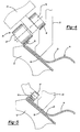
FIG. 1 , a preferred embodiment of thehemming machine 10 of the present invention is shown and comprises anest 12 which is adapted to support apart 14 to be hemmed. As better shown inFIG. 4 , thepart 14 to be hemmed includes an outersheet metal panel 16 having aflange 18 about its outer periphery, and aninner panel 20 nested within theouter flange 18 of theouter panel 16. - Still referring to
FIG. 1 , a hold down 22 is movable relative to thenest 12 between a retracted position, illustrated in phantom line inFIG. 1 , and an extended position, illustrated in solid line inFIG. 1 . In its retracted position, the hold down 22 is spaced from both thenest 12 and thepart 14 to be hemmed thus allowing both a finishedpart 14 to be removed from thenest 12, and a newunhemmed part 14 to be accurately positioned on thenest 12 by retractable "sweepers". Conversely, as best shown inFIG. 4 , in its extended position, the hold down 22 abuts against theinner panel 20 accurately locating it on thepart 14 through locating pins, to bring it into reference with the outer panel. Then it sandwiches the part to be hemmed between the hold down 22 and thenest 12. The hold down 22, when in its extended position, thus prevents movement of thepart 14 relative to thenest 12 during the hemming operation. - As best shown in
FIG. 4 , aguide surface 56 is formed around the outer periphery of the hold down 22. This guide surface conforms to the shape of the desired prehem passes for thepart 14. If two prehem operations are required, the hold down will present two separate tracks located on two separate steps attached to the hold down perimeter. - With reference again to
FIG. 1 , thehemming machine 10 further comprises aprogrammable robot 24 having arobotic arm 26 which is movable, under program control, relative to abase 28 of therobot 24. Therobot 24, furthermore, may be of any conventional construction and includes acontrol system 30 which controls the position of awrist 32 of therobotic arm 26 relative to thebase 24. - With reference now to
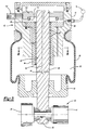
FIGS. 1-3 , a hemminghead 40 includes a base 42 which is mounted to thewrist 32 of therobotic arm 26. As best shown inFIG. 3 , thebase 42 includes alinear guide 44 secured to thebase 42 byfasteners 45, while anelongated piston shaft 46 is slidably mounted through theguide 44. - With reference now particularly to
FIGS. 3 and8 , thepiston shaft 46 includes at least one, and preferably three equidistantly spaced, longitudinally extending wings orridges 100 along the outer surface of thepiston shaft 46. A plurality ofroller bearings 48 are then disposed between receivingchannels 102 formed in thelinear guide 44 and thepiston shaft 46 on both sides of eachwing 100. Theroller bearings 48 enable thepiston shaft 46 to slide in a pure linear longitudinal direction relative to thebase 42 and guide 44 while the coaction between theroller bearings 48 andwings 100 prevents rotation of thepiston shaft 46 about its longitudinal axis. - A
roller hemmer assembly 50 is mounted to oneend 52 of thepiston shaft 46. Theroller assembly 50 includes at least one, and preferably tworollers rollers FIG. 3 as being coaxially rotatably mounted to thepiston 46. - A flexible rolling sleeve
type air bladder 58 sealingly connects the base 42 to apiston end cap 60 attached to thepiston shaft 46. Thebladder 58 thus defines an internalclosed chamber 62 between the base 42 and thepiston 46, which contains and encloses thelinear guide 44. Thischamber 62 is fluidly connected byports source 70 of pressurized fluid, such as pressurized air. Consequently, in operation, the pressurized fluid from thesource 70 pressurizes thebladder chamber 62 and maintains an outward force on thepiston end cap 60 to thepiston shaft 46, together with its attachedroller assembly 50, relative to thebase 42 of thehemmer head 40 and thus relative to thefree end 32 of therobotic arm 26. - With reference now to
FIG. 3 , asensor disc 110 is attached to thepiston shaft 46 at its end opposite from the hemmingrollers position sensor 112 is mounted to the base 42 at a position radially aligned with thedisc 110 and generates an output signal representative of the position of thedisc 110 and thus representative of the degree of extension or retraction of thepiston shaft 46. Consequently, whenever thepiston shaft 46 reaches its fully extended or fully retracted position, indicative of an error or equipment malfunction, thesensor 112 generates an output signal to the operator so that the appropriate corrective action may be taken. Aresilient shock absorber 114 is also preferably attached to thedisc 110 to minimize the possibility of damage to the hemming head in the event thepiston shaft 46 moves to its fully extended position. - With reference again to
FIG. 4 , in operation, the part to be hemmed 14 is mounted on thenest 12 and the hold down 22 is moved to its extended position. In doing so, the hold down 22 clamps thepart 14 against thenest 12 and prevents movement of thepart 20 during the hemming operation. - With reference now to
FIGS. 1 and4 , during the prehemming operations, therobotic arm 26 is manipulated under program control by thecontrol system 30 so that oneroller 54 of theroller hemming head 40 is positioned against one of the tracks of theguide surface 56 formed around the hold down 22. - As the
guide roller 54 is positioned against theguide surface 56 on the hold down 22, therobotic arm 26 manipulates the hemminghead 40, and thus theroller assembly 50, such that theguide roller 54 abuts against and follows the hold downguide surface 56. Simultaneously, the hemmingroller 57 engages theflange 18 on thepart 14 to be hemmed and performs the prehem of theflange 18 in the desired fashion. - It is understood that the same guiding concept can also be applied to guide the hemming roller during the final hem operation, either laterally when a rope profile or any particular profile like a burrs-off kick-off flange has to be done, or to restrict the compression of the flange if an open flange is locally required.
- For example, FIGS. 9-11 all depict the
roller 57 used to perform a final hem. The hemming head optionally uses the hold down 22 as a guide for theroller 54 during the final hem. - During the prehemming operation, the
robot 24 manipulates theroller assembly 50 around the entire periphery of thepart 14 while maintaining theguide roller 54 in abutment with theguide surface 56. Optionally, thenest 12 is swivelly mounted relative to a ground support surface to minimize the necessary extension of therobotic arm 26. In this case therobot 24 first performs a prehem pass around about one half of thepart 14, thenest 12 is swiveled about 180 degrees, and therobot 24 then completes the remainder of the prehem pass. - With reference now to
FIG. 5 , following the hemming operation, therobotic arm 26, under program control, manipulates the roller assembly such that one of the rollers of theroller assembly 50, e.g. theroller 57, engages the previouslyprehemmed flange 18 and compresses theflange 18 against theinner panel 20 to complete the hem between the twopanels part 14. - Although the
rollers FIG. 4 as being coaxially mounted to the hemminghead 40, it is not necessary that therollers FIG. 6 , an alternate embodiment is illustrated in which the tworollers head 40 along parallel, but not coaxial, axes. - Similarly, it is not necessary that the
roller assembly 50 include two or more rollers. For example, as shown inFIG. 7 , asingle roller 70 may be rotatably mounted to the hemminghead 40. In this case, theroller 70 would be dimensioned so that one end of theroller 70 contacts and is guided by theguide surface 56 on the hold down 22 while the opposite end of theroller 70 engages theflange 18 on theouter panel 16 of thepart 14 and performs the hemming operation. - A primary advantage of the present invention is that, since the sleeve encompasses and contains the slide mechanism for the hemming head, the hemming head is very compact. Furthermore, the use of a rolling sleeve type air bladder ensures that a constant pressure is maintained for the hemming rollers regardless of the extension or retraction of the piston shaft assuming, of course, that the piston shaft is neither fully extended nor fully retracted.
- Furthermore, although the hemming head has been described for use with a hold down having a guide surface, it will be understood that the hemming head may be used with hemming machines having a guide surface formed on components other than the hold down, such as the nest.
- From the foregoing, it can be seen that the present invention provides a simple and yet highly effective roller hemming machine which utilizes a guide surface on the part hold down to guide the hemming rollers during the prehemming operation. Having described my invention, however, many modifications thereto will become apparent to those skilled in the art to which it pertains without deviation from the scope of the invention as defined by the appended claims.
Claims (6)
- A hemming machine (10) comprising:a nest (12) adapted to accurately locate and support a part (14) to be hemmed,a hold down (22) movable between a retracted position in which said hold down is spaced from said part and an extended position in which the part is sandwiched between said hold down and said nest,a robotic arm (26),a roller hemming head (40) mounted to said robotic arm,a roller hemmer assembly (50) mounted to said hemming head,wherein said roller hemmer assembly includes a first roller (54) which engages a guide surface (56) during a roller hemming operation of the part,characterized in that
said hold down (22) includes at least one guide surface (56) formed about the periphery of said hold down and said first roller (54) engages said guide surface (56) during said roller hemming operation of the part (14). - The invention as defined in claim 1 wherein said roller hemmer assembly comprises a second roller (57) which engages the part and forms a hem as said first roller engages and travels along said guide surface.
- The invention as defined in claim 2 wherein said first and second rollers are coaxially rotatably mounted to said hemming head (40).
- The invention as defined in claim 1 wherein said hemming head (40) comprises a base (42) attached to said robotic arm, a piston shaft (46) slidably mounted to said base and said hemming head being mounted to said piston.
- The invention as defined in claim 4, a rolling sleeve type inflatable bladder (58) disposed between said piston and said base and forming a chamber (62) around the guiding system, and pressurized fluid source fluidly connected to said chamber.
- The invention as defined in claim 2 wherein said robotic arm manipulates one of said rollers following said prehemming operation so that said one roller engages the part to perform a final hem on said part.
Applications Claiming Priority (3)
| Application Number | Priority Date | Filing Date | Title |
|---|---|---|---|
| US61754204P | 2004-10-08 | 2004-10-08 | |
| US11/247,885 US7124611B2 (en) | 2004-10-08 | 2005-10-10 | Roller hemming machine |
| PCT/US2005/036363 WO2006042199A2 (en) | 2004-10-08 | 2005-10-11 | Roller hemming machine |
Publications (3)
| Publication Number | Publication Date |
|---|---|
| EP1807228A2 EP1807228A2 (en) | 2007-07-18 |
| EP1807228A4 EP1807228A4 (en) | 2011-04-13 |
| EP1807228B1 true EP1807228B1 (en) | 2012-06-06 |
Family
ID=36143919
Family Applications (1)
| Application Number | Title | Priority Date | Filing Date |
|---|---|---|---|
| EP05807732A Expired - Lifetime EP1807228B1 (en) | 2004-10-08 | 2005-10-11 | Roller hemming machine |
Country Status (3)
| Country | Link |
|---|---|
| US (1) | US7124611B2 (en) |
| EP (1) | EP1807228B1 (en) |
| WO (1) | WO2006042199A2 (en) |
Families Citing this family (25)
| Publication number | Priority date | Publication date | Assignee | Title |
|---|---|---|---|---|
| US8359895B2 (en) * | 2003-10-15 | 2013-01-29 | Modern Body Engineering Corporation | Machine cell with vacuum nest for holding a metal panel during a forming operation |
| US20070209420A1 (en) * | 2005-01-14 | 2007-09-13 | Campian Jonathon R | Apparatus and method for holding materials for the forming and joining thereof |
| JP4870479B2 (en) * | 2005-06-21 | 2012-02-08 | 本田技研工業株式会社 | Hemming processing method and hemming processing apparatus |
| JP4939774B2 (en) * | 2005-06-22 | 2012-05-30 | 本田技研工業株式会社 | Roller hemming apparatus and roller hemming method |
| JP4996907B2 (en) * | 2006-10-20 | 2012-08-08 | 本田技研工業株式会社 | Roller hemming method |
| JP5101901B2 (en) * | 2007-02-07 | 2012-12-19 | 本田技研工業株式会社 | Hemming processing method and hemming processing apparatus |
| JP5118384B2 (en) * | 2007-04-19 | 2013-01-16 | 本田技研工業株式会社 | Hemming method |
| DE202007007838U1 (en) * | 2007-06-01 | 2007-09-13 | Edag Engineering + Design Ag | Roller flanging tool used in the production of a wheel housing, sliding roof, engine hood and mudguards comprises a support structure, arms connected to each other in a connecting section and flanging rollers |
| US7987689B2 (en) * | 2007-06-06 | 2011-08-02 | Hirotec America, Inc. | Wheelhouse hemming apparatus and method |
| US8322758B2 (en) * | 2007-09-27 | 2012-12-04 | Langdon Incorporated | Tube coupling and related methods |
| US20090083962A1 (en) * | 2007-09-27 | 2009-04-02 | Langdon Incorporated | Flange-forming system for tube and related methods |
| US7997112B2 (en) | 2007-09-27 | 2011-08-16 | Langdon Incorporated | Flange-forming system for tube and related methods |
| US8024950B2 (en) * | 2008-01-23 | 2011-09-27 | Harrow Aaron E | Vertical air compliant hemming head |
| US20090235712A1 (en) * | 2008-03-24 | 2009-09-24 | Hirotec America, Inc. | Integrated push pull roller head |
| US20090235505A1 (en) * | 2008-03-24 | 2009-09-24 | Hirotec America, Inc. | Hem flange control roller |
| US20090235713A1 (en) * | 2008-03-24 | 2009-09-24 | Hirotec America, Inc. | Magnetically actuated roller head |
| WO2010024760A1 (en) * | 2008-08-27 | 2010-03-04 | Ge Healthcare Bioscience Bioprocess Corp. | A system and method for manufacturing bed supports for chromatography columns |
| US20100281940A1 (en) * | 2009-03-12 | 2010-11-11 | Harrow Aaron E | Vertical air compliant hemming head |
| CN103221161B (en) * | 2010-11-22 | 2015-04-29 | 丰田自动车株式会社 | Roller hemming device |
| EP2662162B1 (en) | 2011-01-07 | 2017-08-16 | Toyota Jidosha Kabushiki Kaisha | Roller hemming device |
| US8640320B2 (en) * | 2011-02-10 | 2014-02-04 | GM Global Technology Operations LLC | Method of joining by roller hemming and solid state welding and system for same |
| EP2689865B1 (en) * | 2012-07-27 | 2016-09-14 | FFT Produktionssysteme GmbH & Co. KG | Hemming press |
| US11331814B2 (en) * | 2018-09-13 | 2022-05-17 | Kinova Inc. | Articulated mechanism with protective sleeve at joint |
| CN110328266B (en) * | 2019-08-16 | 2024-04-09 | 江苏三迪机车制造有限公司 | Folding component and folding method |
| US11845616B1 (en) * | 2020-08-11 | 2023-12-19 | Amazon Technologies, Inc. | Flattening and item orientation correction device |
Family Cites Families (65)
| Publication number | Priority date | Publication date | Assignee | Title |
|---|---|---|---|---|
| JPS61262432A (en) | 1985-05-15 | 1986-11-20 | Torai Eng Kk | Roller type hemming device and its method |
| JP2579530B2 (en) | 1988-06-24 | 1997-02-05 | マツダ株式会社 | Hemming molding method |
| JP2675347B2 (en) | 1988-09-06 | 1997-11-12 | マツダ株式会社 | Hemming molding equipment |
| JPH02197331A (en) | 1989-01-24 | 1990-08-03 | Kanto Auto Works Ltd | Hemming device |
| JPH0829360B2 (en) | 1989-08-15 | 1996-03-27 | 日産自動車株式会社 | Roll hem processing equipment |
| JPH03110030A (en) | 1989-09-22 | 1991-05-10 | Suzuki Motor Corp | Hemming device |
| JP2773336B2 (en) | 1989-12-28 | 1998-07-09 | スズキ株式会社 | Hemming tool |
| JPH04253524A (en) | 1991-01-29 | 1992-09-09 | Mitsubishi Motors Corp | Method and tool for hemming |
| JP2693282B2 (en) | 1991-03-20 | 1997-12-24 | トライエンジニアリング株式会社 | Roller type hemming device and roller type hemming method using the device |
| US5267387A (en) | 1991-08-01 | 1993-12-07 | Triengineering Co., Ltd. | Method for hemming a workpiece having an upturned edge |
| JPH0790299B2 (en) | 1991-08-01 | 1995-10-04 | トライエンジニアリング株式会社 | Roller type hemming method |
| JPH0716733B2 (en) | 1992-01-14 | 1995-03-01 | トライエンジニアリング株式会社 | Roller vibrating hemming device |
| JP3267663B2 (en) | 1992-03-10 | 2002-03-18 | トヨタ自動車株式会社 | Hemming machine |
| EP0577876B1 (en) | 1992-07-09 | 1996-09-04 | TRIENGINEERING Co., Ltd. | Roller type hemming apparatus |
| JP2932129B2 (en) | 1992-09-14 | 1999-08-09 | トヨタ自動車株式会社 | Roller hemming method |
| JP2924569B2 (en) | 1993-06-03 | 1999-07-26 | 日産自動車株式会社 | Hemming device |
| JPH0760370A (en) | 1993-08-04 | 1995-03-07 | Taiho Seiki Co Ltd | Hemming machine |
| JPH0747429A (en) | 1993-08-09 | 1995-02-21 | Taiho Seiki Co Ltd | Hemming machine |
| JPH0768324A (en) | 1993-08-31 | 1995-03-14 | Taiho Seiki Co Ltd | Hemming machine |
| JPH07132327A (en) | 1993-09-14 | 1995-05-23 | Toyota Motor Corp | Roller hemming device |
| JP2682952B2 (en) | 1993-10-25 | 1997-11-26 | トライエンジニアリング株式会社 | Roller type hemming device |
| JPH07124653A (en) | 1993-10-28 | 1995-05-16 | Torai Eng Kk | Combined processing type hemming device |
| JPH07290158A (en) | 1994-04-27 | 1995-11-07 | Toyota Motor Corp | Roller hemming device |
| JPH07299526A (en) | 1994-05-06 | 1995-11-14 | Toyota Motor Corp | Roller for roller hemming device |
| JPH07314054A (en) | 1994-05-23 | 1995-12-05 | Toyota Motor Corp | Method and apparatus for multipurpose roller hemming |
| JPH08164433A (en) | 1994-12-14 | 1996-06-25 | Toyota Motor Corp | Hemming machine |
| JP3337102B2 (en) | 1994-12-28 | 2002-10-21 | 日産自動車株式会社 | Roller type hemming method |
| JP3452165B2 (en) | 1996-02-14 | 2003-09-29 | ダイハツ工業株式会社 | Hemming method for sheet metal work |
| JP3829383B2 (en) | 1996-12-20 | 2006-10-04 | マツダ株式会社 | Roller type hemming method and apparatus |
| JP3573395B2 (en) | 1997-03-12 | 2004-10-06 | ダイハツ工業株式会社 | Hemming device and hemming method |
| JP3595447B2 (en) | 1998-04-23 | 2004-12-02 | ダイハツ工業株式会社 | Hemming device |
| JPH11309528A (en) | 1998-04-24 | 1999-11-09 | Daihatsu Motor Co Ltd | Teaching gauge and teaching method for hemming device |
| JP3824777B2 (en) | 1998-04-30 | 2006-09-20 | 関東自動車工業株式会社 | Roller hemming device |
| JP3722257B2 (en) | 1998-08-25 | 2005-11-30 | 日産自動車株式会社 | Hemming equipment |
| JP3563349B2 (en) * | 1998-09-08 | 2004-09-08 | トライエンジニアリング株式会社 | Roller rolling type processing apparatus and roller rolling type processing method |
| JP3461748B2 (en) | 1999-02-25 | 2003-10-27 | 享栄エンジニアリング株式会社 | Hemming processing method and apparatus used therefor |
| SE513776C2 (en) | 1999-03-18 | 2000-11-06 | Abb Ab | Folding tool, process for its manufacture and use of this tool |
| SE514087C2 (en) | 1999-04-19 | 2000-12-18 | Abb Ab | Process of joining |
| JP2001062530A (en) | 1999-08-31 | 2001-03-13 | Sango Co Ltd | Hemming equipment |
| JP3691696B2 (en) | 1999-09-03 | 2005-09-07 | ダイハツ工業株式会社 | Robot-mounted hemming device |
| JP2001105056A (en) | 1999-10-05 | 2001-04-17 | Mazda Motor Corp | Hemming jig and hemming method |
| US6425277B2 (en) | 1999-12-30 | 2002-07-30 | Unova Ip Corp. | Sheet metal hemming method and apparatus |
| DE10011854C5 (en) | 2000-03-10 | 2013-06-20 | Fft Edag Produktionssysteme Gmbh & Co. Kg | Rollfalzkopf and method for producing a Blechfalzverbindung |
| JP3641995B2 (en) | 2000-03-10 | 2005-04-27 | トヨタ車体株式会社 | Roll hemming method and roll hemming apparatus |
| JP2001314928A (en) | 2000-05-02 | 2001-11-13 | Kyoei Kogyo Kk | Hemming apparatus and hemming method using the same |
| JP3664085B2 (en) | 2000-05-18 | 2005-06-22 | トヨタ車体株式会社 | Roll hemming method and roll hemming apparatus |
| JP4476447B2 (en) | 2000-06-29 | 2010-06-09 | プレス工業株式会社 | Roller hemming device |
| JP3669259B2 (en) | 2000-09-28 | 2005-07-06 | トヨタ車体株式会社 | Roll hemming method and roll hemming apparatus used therefor |
| JP3642020B2 (en) | 2000-11-09 | 2005-04-27 | トヨタ車体株式会社 | Roll hemming method |
| JP3716741B2 (en) | 2000-11-27 | 2005-11-16 | トヨタ車体株式会社 | Roll hemming method |
| JP2002239656A (en) | 2001-02-16 | 2002-08-27 | Toa Kogyo Kk | Hemming equipment |
| JP3664089B2 (en) | 2001-03-13 | 2005-06-22 | トヨタ車体株式会社 | Roll hemming method |
| JP3687559B2 (en) | 2001-04-06 | 2005-08-24 | トヨタ車体株式会社 | Roll hemming device |
| SE0102399D0 (en) | 2001-07-03 | 2001-07-03 | Abb Ab | Flanging device and method |
| KR100883320B1 (en) | 2001-08-31 | 2009-02-11 | 아데아게 엔지니어링 + 디자인 악티엔게젤샤프트 | Rolling Bending Machine for Flange Bending and Rolling Bending Method |
| JP2003103325A (en) | 2001-09-26 | 2003-04-08 | Nissan Motor Co Ltd | Roll hemming apparatus and roll hemming method |
| JP3623474B2 (en) | 2001-10-31 | 2005-02-23 | トライエンジニアリング株式会社 | Hemming apparatus and hemming method |
| JP3886386B2 (en) | 2002-01-30 | 2007-02-28 | ダイハツ工業株式会社 | Hemming processing system and hemming processing method |
| JP4021210B2 (en) | 2002-01-30 | 2007-12-12 | ダイハツ工業株式会社 | Hemming system |
| KR20030081679A (en) * | 2002-04-12 | 2003-10-22 | 현대자동차주식회사 | Roller hemming device |
| DE10392927T5 (en) | 2002-06-26 | 2005-08-25 | Tesco Engineering, Inc., Auburn Hills | Transportable folding device and method |
| FR2843549B1 (en) | 2002-08-13 | 2005-05-27 | Process Conception Ing Sa | METHOD AND DEVICE FOR ASSEMBLING WORKPIECES BY CRIMPING A PERIPHERAL EDGE |
| DE60300614T2 (en) * | 2003-01-20 | 2005-12-01 | Comau S.P.A., Beinasco | Roll-flanging tool and flanging method |
| EP1477155A1 (en) | 2003-05-16 | 2004-11-17 | The Procter & Gamble Company | Compositions comprising an amidine and an alkane polyol |
| US6983633B2 (en) * | 2003-10-24 | 2006-01-10 | Ford Global Technologies, Llc | Apparatus for roll hemming with zero angle deflection |
-
2005
- 2005-10-10 US US11/247,885 patent/US7124611B2/en not_active Expired - Lifetime
- 2005-10-11 EP EP05807732A patent/EP1807228B1/en not_active Expired - Lifetime
- 2005-10-11 WO PCT/US2005/036363 patent/WO2006042199A2/en not_active Ceased
Also Published As
| Publication number | Publication date |
|---|---|
| EP1807228A2 (en) | 2007-07-18 |
| WO2006042199A3 (en) | 2007-02-22 |
| US7124611B2 (en) | 2006-10-24 |
| WO2006042199A2 (en) | 2006-04-20 |
| US20060075797A1 (en) | 2006-04-13 |
| EP1807228A4 (en) | 2011-04-13 |
Similar Documents
| Publication | Publication Date | Title |
|---|---|---|
| US7124611B2 (en) | Roller hemming machine | |
| US7637134B2 (en) | Flanging with a leading and following flanging die | |
| US5228190A (en) | Roller type hemming apparatus | |
| CA2835168C (en) | Hemming head device and method | |
| US5297464A (en) | Rotary shears | |
| US6301525B1 (en) | System and method for controlling a robot | |
| EP0979692A2 (en) | Multi-axis roller hemmer | |
| JPH0270325A (en) | Hemming machine | |
| US5735184A (en) | Powered tool positioner system | |
| US20050086989A1 (en) | Apparatus for roll hemming with zero angle deflection | |
| US7254973B2 (en) | Roller tool and positional pressure method of use for the forming and joining of sheet material | |
| US20160332270A1 (en) | Steady rest | |
| JPH06190706A (en) | Method and device for grinding noncircular workpiece | |
| KR102031653B1 (en) | Active pressure control methodology and apparatus for object shape adaptation of a robot end-effector | |
| JPH05305357A (en) | Roller type hemming device | |
| US7779524B2 (en) | Short-flanged sheet material forming and joining | |
| US20100281940A1 (en) | Vertical air compliant hemming head | |
| US4893963A (en) | System for coupling two bodies, for example a carriage and a machining station | |
| CA1158050A (en) | Grinding machine and method | |
| KR20200068283A (en) | Apparatus for control of pressure as shape-adaptive | |
| JP4476447B2 (en) | Roller hemming device | |
| US4471639A (en) | Roll orientation control system for straightening machines | |
| JP2018043289A (en) | Roller hemming device | |
| US6725700B2 (en) | Bending device and control method thereof | |
| CN118046163A (en) | Fixture, welding system and welding method |
Legal Events
| Date | Code | Title | Description |
|---|---|---|---|
| PUAI | Public reference made under article 153(3) epc to a published international application that has entered the european phase |
Free format text: ORIGINAL CODE: 0009012 |
|
| 17P | Request for examination filed |
Effective date: 20070508 |
|
| AK | Designated contracting states |
Kind code of ref document: A2 Designated state(s): AT BE BG CH CY CZ DE DK EE ES FI FR GB GR HU IE IS IT LI LT LU LV MC NL PL PT RO SE SI SK TR |
|
| AX | Request for extension of the european patent |
Extension state: AL BA HR MK YU |
|
| DAX | Request for extension of the european patent (deleted) | ||
| A4 | Supplementary search report drawn up and despatched |
Effective date: 20110315 |
|
| GRAP | Despatch of communication of intention to grant a patent |
Free format text: ORIGINAL CODE: EPIDOSNIGR1 |
|
| GRAS | Grant fee paid |
Free format text: ORIGINAL CODE: EPIDOSNIGR3 |
|
| GRAA | (expected) grant |
Free format text: ORIGINAL CODE: 0009210 |
|
| AK | Designated contracting states |
Kind code of ref document: B1 Designated state(s): AT BE BG CH CY CZ DE DK EE ES FI FR GB GR HU IE IS IT LI LT LU LV MC NL PL PT RO SE SI SK TR |
|
| REG | Reference to a national code |
Ref country code: GB Ref legal event code: FG4D |
|
| REG | Reference to a national code |
Ref country code: AT Ref legal event code: REF Ref document number: 560751 Country of ref document: AT Kind code of ref document: T Effective date: 20120615 Ref country code: CH Ref legal event code: EP |
|
| REG | Reference to a national code |
Ref country code: IE Ref legal event code: FG4D |
|
| REG | Reference to a national code |
Ref country code: DE Ref legal event code: R096 Ref document number: 602005034577 Country of ref document: DE Effective date: 20120802 |
|
| REG | Reference to a national code |
Ref country code: NL Ref legal event code: VDEP Effective date: 20120606 |
|
| PG25 | Lapsed in a contracting state [announced via postgrant information from national office to epo] |
Ref country code: LT Free format text: LAPSE BECAUSE OF FAILURE TO SUBMIT A TRANSLATION OF THE DESCRIPTION OR TO PAY THE FEE WITHIN THE PRESCRIBED TIME-LIMIT Effective date: 20120606 Ref country code: FI Free format text: LAPSE BECAUSE OF FAILURE TO SUBMIT A TRANSLATION OF THE DESCRIPTION OR TO PAY THE FEE WITHIN THE PRESCRIBED TIME-LIMIT Effective date: 20120606 Ref country code: CY Free format text: LAPSE BECAUSE OF FAILURE TO SUBMIT A TRANSLATION OF THE DESCRIPTION OR TO PAY THE FEE WITHIN THE PRESCRIBED TIME-LIMIT Effective date: 20120606 Ref country code: SE Free format text: LAPSE BECAUSE OF FAILURE TO SUBMIT A TRANSLATION OF THE DESCRIPTION OR TO PAY THE FEE WITHIN THE PRESCRIBED TIME-LIMIT Effective date: 20120606 |
|
| REG | Reference to a national code |
Ref country code: AT Ref legal event code: MK05 Ref document number: 560751 Country of ref document: AT Kind code of ref document: T Effective date: 20120606 |
|
| REG | Reference to a national code |
Ref country code: LT Ref legal event code: MG4D Effective date: 20120606 |
|
| PG25 | Lapsed in a contracting state [announced via postgrant information from national office to epo] |
Ref country code: GR Free format text: LAPSE BECAUSE OF FAILURE TO SUBMIT A TRANSLATION OF THE DESCRIPTION OR TO PAY THE FEE WITHIN THE PRESCRIBED TIME-LIMIT Effective date: 20120907 Ref country code: LV Free format text: LAPSE BECAUSE OF FAILURE TO SUBMIT A TRANSLATION OF THE DESCRIPTION OR TO PAY THE FEE WITHIN THE PRESCRIBED TIME-LIMIT Effective date: 20120606 Ref country code: SI Free format text: LAPSE BECAUSE OF FAILURE TO SUBMIT A TRANSLATION OF THE DESCRIPTION OR TO PAY THE FEE WITHIN THE PRESCRIBED TIME-LIMIT Effective date: 20120606 |
|
| PG25 | Lapsed in a contracting state [announced via postgrant information from national office to epo] |
Ref country code: AT Free format text: LAPSE BECAUSE OF FAILURE TO SUBMIT A TRANSLATION OF THE DESCRIPTION OR TO PAY THE FEE WITHIN THE PRESCRIBED TIME-LIMIT Effective date: 20120606 Ref country code: RO Free format text: LAPSE BECAUSE OF FAILURE TO SUBMIT A TRANSLATION OF THE DESCRIPTION OR TO PAY THE FEE WITHIN THE PRESCRIBED TIME-LIMIT Effective date: 20120606 Ref country code: SK Free format text: LAPSE BECAUSE OF FAILURE TO SUBMIT A TRANSLATION OF THE DESCRIPTION OR TO PAY THE FEE WITHIN THE PRESCRIBED TIME-LIMIT Effective date: 20120606 Ref country code: NL Free format text: LAPSE BECAUSE OF FAILURE TO SUBMIT A TRANSLATION OF THE DESCRIPTION OR TO PAY THE FEE WITHIN THE PRESCRIBED TIME-LIMIT Effective date: 20120606 Ref country code: EE Free format text: LAPSE BECAUSE OF FAILURE TO SUBMIT A TRANSLATION OF THE DESCRIPTION OR TO PAY THE FEE WITHIN THE PRESCRIBED TIME-LIMIT Effective date: 20120606 Ref country code: IS Free format text: LAPSE BECAUSE OF FAILURE TO SUBMIT A TRANSLATION OF THE DESCRIPTION OR TO PAY THE FEE WITHIN THE PRESCRIBED TIME-LIMIT Effective date: 20121006 Ref country code: BE Free format text: LAPSE BECAUSE OF FAILURE TO SUBMIT A TRANSLATION OF THE DESCRIPTION OR TO PAY THE FEE WITHIN THE PRESCRIBED TIME-LIMIT Effective date: 20120606 |
|
| PG25 | Lapsed in a contracting state [announced via postgrant information from national office to epo] |
Ref country code: PT Free format text: LAPSE BECAUSE OF FAILURE TO SUBMIT A TRANSLATION OF THE DESCRIPTION OR TO PAY THE FEE WITHIN THE PRESCRIBED TIME-LIMIT Effective date: 20121008 Ref country code: PL Free format text: LAPSE BECAUSE OF FAILURE TO SUBMIT A TRANSLATION OF THE DESCRIPTION OR TO PAY THE FEE WITHIN THE PRESCRIBED TIME-LIMIT Effective date: 20120606 |
|
| PLBE | No opposition filed within time limit |
Free format text: ORIGINAL CODE: 0009261 |
|
| STAA | Information on the status of an ep patent application or granted ep patent |
Free format text: STATUS: NO OPPOSITION FILED WITHIN TIME LIMIT |
|
| PG25 | Lapsed in a contracting state [announced via postgrant information from national office to epo] |
Ref country code: DK Free format text: LAPSE BECAUSE OF FAILURE TO SUBMIT A TRANSLATION OF THE DESCRIPTION OR TO PAY THE FEE WITHIN THE PRESCRIBED TIME-LIMIT Effective date: 20120606 Ref country code: ES Free format text: LAPSE BECAUSE OF FAILURE TO SUBMIT A TRANSLATION OF THE DESCRIPTION OR TO PAY THE FEE WITHIN THE PRESCRIBED TIME-LIMIT Effective date: 20120917 |
|
| 26N | No opposition filed |
Effective date: 20130307 |
|
| PG25 | Lapsed in a contracting state [announced via postgrant information from national office to epo] |
Ref country code: MC Free format text: LAPSE BECAUSE OF NON-PAYMENT OF DUE FEES Effective date: 20121031 |
|
| REG | Reference to a national code |
Ref country code: CH Ref legal event code: PL |
|
| GBPC | Gb: european patent ceased through non-payment of renewal fee |
Effective date: 20121011 |
|
| REG | Reference to a national code |
Ref country code: DE Ref legal event code: R097 Ref document number: 602005034577 Country of ref document: DE Effective date: 20130307 |
|
| REG | Reference to a national code |
Ref country code: IE Ref legal event code: MM4A |
|
| PG25 | Lapsed in a contracting state [announced via postgrant information from national office to epo] |
Ref country code: CH Free format text: LAPSE BECAUSE OF NON-PAYMENT OF DUE FEES Effective date: 20121031 Ref country code: GB Free format text: LAPSE BECAUSE OF NON-PAYMENT OF DUE FEES Effective date: 20121011 Ref country code: IE Free format text: LAPSE BECAUSE OF NON-PAYMENT OF DUE FEES Effective date: 20121011 Ref country code: LI Free format text: LAPSE BECAUSE OF NON-PAYMENT OF DUE FEES Effective date: 20121031 Ref country code: BG Free format text: LAPSE BECAUSE OF FAILURE TO SUBMIT A TRANSLATION OF THE DESCRIPTION OR TO PAY THE FEE WITHIN THE PRESCRIBED TIME-LIMIT Effective date: 20120906 |
|
| PG25 | Lapsed in a contracting state [announced via postgrant information from national office to epo] |
Ref country code: TR Free format text: LAPSE BECAUSE OF FAILURE TO SUBMIT A TRANSLATION OF THE DESCRIPTION OR TO PAY THE FEE WITHIN THE PRESCRIBED TIME-LIMIT Effective date: 20120606 |
|
| PG25 | Lapsed in a contracting state [announced via postgrant information from national office to epo] |
Ref country code: LU Free format text: LAPSE BECAUSE OF NON-PAYMENT OF DUE FEES Effective date: 20121011 |
|
| PG25 | Lapsed in a contracting state [announced via postgrant information from national office to epo] |
Ref country code: HU Free format text: LAPSE BECAUSE OF FAILURE TO SUBMIT A TRANSLATION OF THE DESCRIPTION OR TO PAY THE FEE WITHIN THE PRESCRIBED TIME-LIMIT Effective date: 20051011 |
|
| REG | Reference to a national code |
Ref country code: FR Ref legal event code: PLFP Year of fee payment: 12 |
|
| REG | Reference to a national code |
Ref country code: FR Ref legal event code: PLFP Year of fee payment: 13 |
|
| REG | Reference to a national code |
Ref country code: FR Ref legal event code: PLFP Year of fee payment: 14 |
|
| PGFP | Annual fee paid to national office [announced via postgrant information from national office to epo] |
Ref country code: IT Payment date: 20191009 Year of fee payment: 15 |
|
| PGFP | Annual fee paid to national office [announced via postgrant information from national office to epo] |
Ref country code: FR Payment date: 20201026 Year of fee payment: 16 Ref country code: DE Payment date: 20201013 Year of fee payment: 16 Ref country code: CZ Payment date: 20201026 Year of fee payment: 16 |
|
| PG25 | Lapsed in a contracting state [announced via postgrant information from national office to epo] |
Ref country code: IT Free format text: LAPSE BECAUSE OF NON-PAYMENT OF DUE FEES Effective date: 20201011 |
|
| REG | Reference to a national code |
Ref country code: DE Ref legal event code: R119 Ref document number: 602005034577 Country of ref document: DE |
|
| PG25 | Lapsed in a contracting state [announced via postgrant information from national office to epo] |
Ref country code: CZ Free format text: LAPSE BECAUSE OF NON-PAYMENT OF DUE FEES Effective date: 20211011 |
|
| PG25 | Lapsed in a contracting state [announced via postgrant information from national office to epo] |
Ref country code: DE Free format text: LAPSE BECAUSE OF NON-PAYMENT OF DUE FEES Effective date: 20220503 |
|
| PG25 | Lapsed in a contracting state [announced via postgrant information from national office to epo] |
Ref country code: FR Free format text: LAPSE BECAUSE OF NON-PAYMENT OF DUE FEES Effective date: 20211031 |