EP1806867A2 - Procédé et appareil de multiplexage temporel de données sortantes et d'informations de signalisation sortantes dans un système SC-FDMA - Google Patents
Procédé et appareil de multiplexage temporel de données sortantes et d'informations de signalisation sortantes dans un système SC-FDMA Download PDFInfo
- Publication number
- EP1806867A2 EP1806867A2 EP07000358A EP07000358A EP1806867A2 EP 1806867 A2 EP1806867 A2 EP 1806867A2 EP 07000358 A EP07000358 A EP 07000358A EP 07000358 A EP07000358 A EP 07000358A EP 1806867 A2 EP1806867 A2 EP 1806867A2
- Authority
- EP
- European Patent Office
- Prior art keywords
- uplink
- pilot
- data
- channel
- uplink data
- Prior art date
- Legal status (The legal status is an assumption and is not a legal conclusion. Google has not performed a legal analysis and makes no representation as to the accuracy of the status listed.)
- Withdrawn
Links
Images


Classifications
-
- H—ELECTRICITY
- H04—ELECTRIC COMMUNICATION TECHNIQUE
- H04L—TRANSMISSION OF DIGITAL INFORMATION, e.g. TELEGRAPHIC COMMUNICATION
- H04L1/00—Arrangements for detecting or preventing errors in the information received
- H04L1/12—Arrangements for detecting or preventing errors in the information received by using return channel
- H04L1/16—Arrangements for detecting or preventing errors in the information received by using return channel in which the return channel carries supervisory signals, e.g. repetition request signals
- H04L1/1607—Details of the supervisory signal
- H04L1/1664—Details of the supervisory signal the supervisory signal being transmitted together with payload signals; piggybacking
-
- H—ELECTRICITY
- H04—ELECTRIC COMMUNICATION TECHNIQUE
- H04L—TRANSMISSION OF DIGITAL INFORMATION, e.g. TELEGRAPHIC COMMUNICATION
- H04L27/00—Modulated-carrier systems
- H04L27/26—Systems using multi-frequency codes
- H04L27/2601—Multicarrier modulation systems
- H04L27/2602—Signal structure
- H04L27/261—Details of reference signals
- H04L27/2613—Structure of the reference signals
- H04L27/26134—Pilot insertion in the transmitter chain, e.g. pilot overlapping with data, insertion in time or frequency domain
-
- H—ELECTRICITY
- H04—ELECTRIC COMMUNICATION TECHNIQUE
- H04L—TRANSMISSION OF DIGITAL INFORMATION, e.g. TELEGRAPHIC COMMUNICATION
- H04L27/00—Modulated-carrier systems
- H04L27/26—Systems using multi-frequency codes
- H04L27/2601—Multicarrier modulation systems
- H04L27/2626—Arrangements specific to the transmitter only
- H04L27/2627—Modulators
- H04L27/2634—Inverse fast Fourier transform [IFFT] or inverse discrete Fourier transform [IDFT] modulators in combination with other circuits for modulation
- H04L27/2636—Inverse fast Fourier transform [IFFT] or inverse discrete Fourier transform [IDFT] modulators in combination with other circuits for modulation with FFT or DFT modulators, e.g. standard single-carrier frequency-division multiple access [SC-FDMA] transmitter or DFT spread orthogonal frequency division multiplexing [DFT-SOFDM]
-
- H—ELECTRICITY
- H04—ELECTRIC COMMUNICATION TECHNIQUE
- H04L—TRANSMISSION OF DIGITAL INFORMATION, e.g. TELEGRAPHIC COMMUNICATION
- H04L27/00—Modulated-carrier systems
- H04L27/26—Systems using multi-frequency codes
- H04L27/2601—Multicarrier modulation systems
- H04L27/2647—Arrangements specific to the receiver only
Definitions
- the present invention relates to a method and an apparatus for transmitting/receiving uplink signaling information and uplink data in a Frequency Division Multiple Access (FDMA) wireless communication system using a single carrier.
- FDMA Frequency Division Multiple Access
- OFDM Orthogonal Frequency Division Multiplexing
- SC-FDMA Single Carrier-Frequency Division Multiple Access
- the OFDM scheme which transmits data using multiple carriers, is a special type of a Multiple Carrier Modulation (MCM) scheme in which a serial symbol sequence is converted into parallel symbol sequences, and the parallel symbol sequences are modulated with a plurality of mutually orthogonal subcarriers (or subcarrier channels) before being transmitted.
- MCM Multiple Carrier Modulation
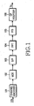
- FIG. 1 is a block diagram illustrating a structure of a transmitter of a typical OFDM system.
- the OFDM transmitter includes a channel encoder 101, a modulator 102, a serial-to-parallel converter 103, an Inverse Fast Fourier Transform (IFFT) block or a Digital Fourier Transform (DFT) block 104, a parallel-to-serial converter 105, and a Cyclic Prefix (CP) inserter 106.
- IFFT Inverse Fast Fourier Transform
- DFT Digital Fourier Transform
- CP Cyclic Prefix
- the channel encoder 101 receives and channel-encodes an input information bit sequence.
- a convolutional encoder, a turbo encoder, or a Low Density Parity Check (LDPC) encoder is used as the channel encoder 101.
- the modulator 102 modulates the channel-encoded bit sequence according to a modulation scheme, such as a Quadrature Phase Shift Keying (QPSK) scheme, 8PSK scheme, 16-ary Quadrature Amplitude Modulation (16QAM) scheme, 64QAM, 256QAM, etc.
- QPSK Quadrature Phase Shift Keying
- 8PSK 8PSK
- 16QAM 16-ary Quadrature Amplitude Modulation
- 64QAM 64QAM
- 256QAM 256QAM
- the serial-to-parallel converter 103 receives output data from the modulator 102 and converts the received data into parallel data.
- the IFFT block 104 receives the parallel data output from the serial-to-parallel converter 103 and performs an IFFT operation on the parallel data.
- the data output from the IFFT block 104 is converted to serial data by the parallel-to-serial converter 105.
- the CP inserter 106 inserts a Cyclic Prefix (CP) into the serial data output from the parallel-to-serial converter 105, thereby generating an OFDM symbol to be transmitted.
- CP Cyclic Prefix
- the IFFT block 104 converts the input data of the frequency domain to output data of the time domain.
- a Peak to Average Power Ratio (PAPR) of the data may increase when the data has been converted into the time domain.
- the PAPR is one of the most important factors to be considered in the uplink transmission. As the PAPR increases, the cell coverage decreases, so that the signal power required by a User Equipment (UE) increases. Therefore, it is necessary to first reduce the PAPR, and it is thus possible to use an SC-FDMA scheme, which is a scheme modified from the typical OFDM scheme, for the OFDM-based uplink transmission. It is possible to effectively reduce the PAPR by enabling processing in the time domain without performing processing (channel encoding, modulation, etc.) of data in the frequency domain.
- SC-FDMA scheme which is a scheme modified from the typical OFDM scheme
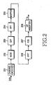
- FIG. 2 is a block diagram illustrating a structure of a transmitter in a system employing an SC-FDMA scheme, which is a typical uplink transmission scheme.
- the SC-FDMA transmitter includes a channel encoder 201, a modulator 202, a serial-to-parallel converter 203, a Fast Fourier Transform (FFT) block 204, a sub-carrier mapper 205, an IFFT block 206, a parallel-to-serial converter 207, and a CP inserter 208.
- FFT Fast Fourier Transform
- the channel encoder 201 receives and channel-encodes an input information bit sequence.
- the modulator 202 modulates the output of the channel encoder 201 according to a modulation scheme, such as a QPSK scheme, an 8PSK scheme, a 16QAM scheme, a 64QAM scheme, a 256QAM scheme, etc.
- a rate matching block (not shown) may be included between the channel encoder 201 and the modulator 202.
- the serial-to-parallel converter 203 receives data output from the modulator 202 and converts the received data into parallel data.
- the FFT block 204 performs an FFT operation on the data output from the serial-to-parallel converter 203, thereby converting the data into data of the frequency domain.
- the sub-carrier mapper 205 maps the output data of the FFT block 204 to the input of the IFFT block 206.
- the IFFT block 206 performs an IFFT operation on the data output from the sub-carrier mapper 205.
- the output data of the IFFT block 206 is converted to parallel data by the parallel-to-serial converter 207.
- the CP inserter 208 inserts a CP into the parallel data output from the parallel-to-serial converter 207, thereby generating an OFDM symbol to be transmitted.
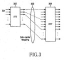
- FIG. 3 is a block diagram illustrating in more detail the structure for resource mapping shown in FIG. 2.
- the operation of the sub-carrier mapper 205 will be described with reference to FIG. 3.
- data symbols 301 having been subjected to the channel encoding and modulation are input to an FFT block 302.
- the output of the FFT block 302 is input to an IFFT block 304.
- a sub-carrier mapper 303 maps the output data of the FFT block 302 to the input data of the IFFT block 304.
- the sub-carrier mapper 303 maps the information symbols of the frequency domain data converted by the FFT block 302 to corresponding input points or input taps of the IFFT block 304 so that the information symbols can be carried by proper sub-carriers.
- mapping procedure if the output symbols of the FFT block 302 are sequentially mapped to neighboring input points of the IFFT block 304, the output symbols are transmitted by sub-carriers that are consecutive in the frequency domain.
- This mapping scheme is referred to as a Localized Frequency Division Multiple Access (LFDMA) scheme.
- LFDMA Localized Frequency Division Multiple Access
- mapping scheme is referred to as either an Interleaved Frequency Division Multiple Access (IFDMA) scheme or a Distributed Frequency Division Multiple Access (DFDMA) scheme.
- IFDMA Interleaved Frequency Division Multiple Access
- DFDMA Distributed Frequency Division Multiple Access
- FIGs. 2 and 3 show one method of implementing the SC-FDMA technology in the frequency domain, it is also possible to use various other methods, such as a method of implementing the technology in the time domain.
- Diagrams (a) and (b) of FIG. 4 illustrates comparison between the positions of sub-carriers used for the DFDMA and the LFDMA in the frequency domain.
- the transmission symbols of a UE using the DFDMA scheme are distributed with equal intervals over the entire frequency domain (that is, the system band).
- the transmission symbols of a UE using the LFDMA scheme are consecutively located at some part of the frequency domain.
- the LFDMA scheme because consecutive parts of the entire frequency band are used, it is possible to obtain a frequency scheduling gain by selecting a partial frequency band having good channel gain in the frequency selective channel environment in which severe channel change of frequency bands occurs.
- the DFDMA scheme it is possible to obtain a frequency diversity gain as transmission symbols have various channel gains by using a large number of sub-carriers distributed over a wide frequency band.
- simultaneously transmitted information symbols should be mapped to the IFFT block such that they can always satisfy the LFDMA or DFDMA after passing through a single FFT block (or DFT block).
- various information symbols may be transmitted.
- uplink data which includes Transport Format (TF) information of the uplink data and/or Hybrid Automatic Repeat reQuest (HARQ) information
- ACK/NACK for an HARQ operation for downlink data
- CQI Channel Quality Indication
- Uplink data can be transmitted in a situation in which a UE has data in a transmission buffer of the UE and has received permission for uplink transmission from a node B.
- the control information regulating the transport scheme of the uplink data is transmitted only when the uplink data is transmitted.
- uplink data may be transmitted without transmission of control information.
- the ACK/NACK which is transmitted in response to downlink data, has no relation to the transmission of the uplink data. That is, either both the uplink data and the ACK/NACK may be simultaneously transmitted or only one of them may be transmitted.
- the CQI which is transmitted at a given time, also has no relation to the transmission of the uplink data. That is, either both the uplink data and the CQI may be simultaneously transmitted or only one of them may be transmitted.
- the present invention has been made to solve the above-mentioned problems occurring in the prior art, and provides a method and an apparatus for transmitting various types of uplink information having various characteristics by using a single FFT block.
- the present invention also provides a method and an apparatus for time multiplexing uplink data and uplink signaling information.
- the present invention also provides a method and an apparatus for transmitting an additional pilot signal necessary for the transmission of uplink signaling information.
- a method for transmitting multiple types of uplink information in a Single Carrier Frequency Division Multiple Access (SC-FDMA) wireless communication system including, when there is uplink data to be transmitted, determining if there is uplink signaling information to be transmitted; when there is no uplink signaling information, time-multiplexing the uplink data and a first pilot for the uplink data and transmitting the multiplexed uplink data and first pilot; and when there exists the uplink signaling information, time-multiplexing the uplink data, the first pilot for the uplink data, and a second pilot for the uplink data and the uplink signaling information, and transmitting the multiplexed uplink data, first pilot, and second pilot.
- SC-FDMA Single Carrier Frequency Division Multiple Access
- an apparatus for transmitting multiple types of uplink information in a Single Carrier Frequency Division Multiple Access (SC-FDMA) wireless communication system including a multiplexer for time multiplexing uplink data and a first pilot for the uplink data when there is uplink data to be transmitted and there is no uplink signaling information, and time multiplexing the uplink data, the first pilot for the uplink data, and a second pilot for the uplink data and the uplink signaling information when there is both the uplink signaling information and the uplink signaling information; and a resource mapper for transmitting an output of the multiplexer after mapping the output of the multiplexer to a frequency resource.
- SC-FDMA Single Carrier Frequency Division Multiple Access
- a method for receiving multiple types of uplink information in a Single Carrier Frequency Division Multiple Access (SC-FDMA) wireless communication system including receiving from a UE a radio signal through a frequency resource; time-demultiplexing the radio signal into uplink data related signal, a first pilot, uplink signaling related signal, and a second pilot; channel-compensating the uplink data related signal by using the first pilot; decoding the channel-compensated uplink data related signal and outputting uplink data; channel-compensating the uplink signaling related signal by using the second pilot; and decoding the channel-compensated uplink signaling related signal and outputting uplink signaling information.
- SC-FDMA Single Carrier Frequency Division Multiple Access
- an apparatus for receiving multiple types of uplink information in a Single Carrier Frequency Division Multiple Access (SC-FDMA) wireless communication system including a receiver block for receiving from a UE a radio signal through a frequency resource; a first demultiplexer for time-demultiplexing the radio signal into uplink data related signal, a first pilot, uplink signaling related signal, and a second pilot; a first channel estimator/compensator for channel-compensating the uplink data related signal by using the first pilot; a first channel decoder for decoding the channel-compensated uplink data related signal and outputting uplink data; a second channel estimator/compensator for channel-compensating the uplink signaling related signal by using the second pilot; and a second channel decoder for decoding the channel-compensated uplink signaling related signal and outputting uplink signaling information.
- SC-FDMA Single Carrier Frequency Division Multiple Access
- the present invention multiplexes different types of uplink information, so as to enable transmission of the uplink information, which can satisfy the single carrier characteristic in a wireless communication system using a Single Carrier Frequency Division Multiple Access (SC-FDMA) scheme.
- SC-FDMA Single Carrier Frequency Division Multiple Access
- the following description discusses multiplexing for uplink transmission of uplink data, control information, ACK/NACK, CQI, etc. in an SC-FDMA wireless communication system.
- the other information except for the uplink data and control information thereof, that is, information including ACK/NACK and CQI is referred to as "uplink signaling information.”
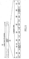
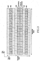
- FIG. 5 illustrates structures of an uplink transmission frame and its sub-frame.
- reference numeral 501 denotes a radio frame, which is an uplink transmission unit and is defined to have a length of 10 ms.
- One radio frame 501 includes 20 sub-frames 502, each of which has a length of 0.5 ms.
- each sub-frame 502 includes six Long Blocks (LBs) 503, 505, 506, 507, 508 and 510, two Short Blocks (SBs) 504 and 509, and Cyclic Prefixes (CPs) 511 and 512 located before the blocks.
- the LBs 503, 505, 506, 507, 508 and 510 carry information except for pilot signals or pilots used as a reference for coherent modulation, and SBs 504 and 509 are used only to carry the pilots.
- FIG. 6 illustrates the sub-frame 502 of FIG. 5 on the time domain and the frequency domain.
- the horizontal axis indicates the frequency domain 601 and the vertical axis indicates the time domain 602.
- the range of the frequency domain 601 corresponds to the entire frequency band 604 and the range of the time domain 602 corresponds to one sub-frame 603.
- the SBs 605 and 606 carry pilots
- the LBs 607 and 608 carry other information except for the pilots.
- uplink data transmitted according to resource allocation by a node B control information in relation to the uplink data, ACK/NACK for indicating success or failure in reception of downlink data, CQI for indicating a channel status, scheduling request information, etc. are transmitted by using the uplink resources.
- Whether to transmit the uplink data is determined according to the scheduling of a node B, and a resource to be used is also determined according to the resource allocation by the node B.
- the control information transmitted together with the uplink data is also transmitted according to the resources allocated by the node B.
- the ACK/NACK is generated based on downlink data
- the ACK/NACK is transmitted using an uplink resource automatically allocated according to whether or not the downlink data is transmitted, in response to the control channel defining the downlink data or the downlink data channel.
- the CQI since it is usual that the CQI is periodically transmitted, the CQI is transmitted using a resource determined in advance through setup by higher level signaling.
- FIG. 7 illustrates a process of signal transmission/reception between a node B and a UE.
- the node B 701 may transmit downlink data 704, downlink control information 703 defining a transform format of the downlink data 704, an uplink grant 702 for allocating an uplink resource of the UE according to a result of scheduling, etc. to the UE 705.
- the UE 705 may transmit uplink data 707, and ACK/NACK 706 for supporting an HARQ operation of the downlink data 704 from the node B 701, etc. to the node B 701.
- the UE 705 may further transmit uplink signaling information such as CQI indicating the channel information.
- ACK/NACK is transmitted as one of a representative uplink signaling information.
- control information for the uplink data may be also transmitted together with the uplink data 707.
- the following discussion can be applied to not only the ACK/NACK but also other uplink signaling information such as CQI or scheduling request information.
- the node B 701 transmits downlink control information 708 together with downlink data 709.
- the control information 708 and the downlink data 709 are transmitted at either exactly the same transmission time or nearly similar transmission time.
- the UE 705 decodes the downlink data 709 based on the downlink control information 708. Then, the UE 705 informs the node B 701 of if the decoding of the downlink data 709 was successful. Specifically, in step 715, the UE 705 transmits NACK, which implies that the received downlink data has an error.
- the node B 701 transmits the uplink grant 710, which is resource allocation information for uplink transmission of the UE 705.
- the UE 705 Upon receiving the uplink grant 710, the UE 705 transmits uplink data 714 together with control information through an uplink resource indicated by the uplink grant 710 in step 716.
- the radio resource for transmitting the ACK/NACK 706 must be set in advance. Since the ACK/NACK 706 relates to the transmission of the downlink data 704, the ACK/NACK 706 is transmitted by using either an uplink radio resource mapped to the downlink resource used by the downlink control information 703 or an uplink radio resource mapped to the downlink resource used by the downlink data 704. At this time, the mapping of the radio resource corresponding to the ACK/NACK 706 may change according to time, and it is possible to enable the node B to know the channel statuses corresponding to various sub-carriers, that is, corresponding to detailed frequency bands, by changing the sub-carrier(s) carrying the ACK/NACK 706.
- the UE 705 recognizes, by using the uplink grant 702, the uplink radio resource to be used for the uplink data 707.
- the UE 705 can maintain without difficulty the single carrier characteristic of the uplink transmission.
- the node B 701 Upon receiving the NACK 713, the node B 701 retransmits downlink data 717 substantially equal to the downlink data 709 according to the HARQ operation in step 719.
- control information of the retransmitted downlink data 717 is transmitted.
- the UE 705 transmits ACK 720 in response to the retransmitted downlink data 717. Then, the HARQ operation for the downlink data 709 and 717 is terminated.
- the UE 705 transmits only the ACK 720 without the uplink data. Therefore, the UE 705 can maintain without difficulty the single carrier characteristic of the uplink transmission.
- the UE 705 uplink transmits the ACK/NACK 736 and the uplink data 735 substantially at the same time in steps 737 and 738.
- the radio resource for the ACK/NACK 736 is determined based on the downlink data 731 or the downlink control information 730 and the radio resource for the uplink data 735 is determined based on the uplink grant 732, and these radio resources are usually divided by the frequency side within one sub-frame.
- the UE 705 must simultaneously transmit the uplink data 735 and the ACK/NACK 736, it is impossible to contain the two types of information 735 and 736 in one FFT block and it is thus impossible to satisfy the single carrier characteristic of the uplink transmission.
- the ACK/NACK (that is, uplink signaling information) and the uplink data are time-multiplexed and transmitted within the same frequency resource, in order to always satisfy the single carrier characteristic of the uplink transmission regardless of the transmission of the ACK/NACK and the uplink data within one sub-frame, which is the minimum transmission unit.
- FIG. 8 illustrates a sub-frame structure for time-multiplexing the ACK/NACK and uplink data according to the present invention.
- the horizontal axis corresponds to the frequency domain 801
- the vertical axis corresponds to the time domain 802.
- the range of the frequency domain 801 corresponds to the entire frequency band 804, and the range of the time domain 802 corresponds to one sub-frame 803.
- short blocks 805 and 806 carry pilots
- long blocks 807 carry uplink data and control information defining the transform format of the uplink data except for the pilots.
- the ACK/NACK is transmitted through a separate resource (ACK/NACK resource) 808 that is temporally discriminated from the resource (data resource) for the uplink data.
- the length of the time interval for the ACK/NACK may be the same as the size of each short block or the size of each long block, or may be another size. Further, the ACK/NACK resource may be variably determined according to the used frequency band, etc.
- short blocks 805 and 806 carry pilots, which are used in channel estimation for radio resources (data resources) of uplink data transmitted through the long blocks 807.
- the ACK/NACK is transmitted at a different time point from that of the uplink data, all of the pilots are used for the uplink data and it is impossible to perform the channel estimation for the radio resource (ACK/NACK resource). If the ACK/NACK is restored according to a non-coherent scheme without channel estimation, the transmission performance is degraded in comparison with the case including the channel estimation.
- a second pilot for the ACK/NACK having been time-multiplexed with the uplink data within the same sub-frame is used in addition to the first pilot for the uplink data. That is, the present invention additionally uses the second pilot for the ACK/NACK, and frequency hopping may be applied to the second pilot to be used in the uplink channel estimation of the node B. It is of course possible to apply such a technology to not only transmission of the ACK/NACK but also transmission of other uplink signaling information.
- FIG. 9 illustrates a structure of a sub-frame including the second pilot additionally used for the ACK/NACK according to the present invention.
- the horizontal axis corresponds to the frequency domain 901
- the vertical axis corresponds to the time domain 902.
- the range of the frequency domain 901 corresponds to the entire frequency band 904, and the range of the time domain 902 corresponds to one sub-frame 903.
- short blocks 905 and 906 carry the first pilots
- long blocks 907 carry uplink data and control information defining the transform format of the uplink data.
- the ACK/NACK is transmitted through a separate resource (ACK/NACK resource) 908 that is temporally discriminated from the resource (data resource) for the uplink data.
- the second pilot for estimation of the channel in relation to the ACK/NACK is transmitted to a time resource 909 just adjacent to the ACK/NACK resource 908, thereby reflecting the channel status of the ACK/NACK. Due to the use of the ACK/NACK and the second pilot, one sub-frame may have five or less long blocks.
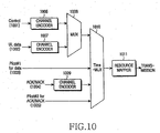
- FIG. 10 is a block diagram illustrating a structure of a transmitter (UE) for time-multiplexing data and ACK/NACK according to the present invention.
- the uplink data 1002 and the control information 1001 defining the transmit format of the uplink data 1002 are input to channel encoders 1006 and 1007, and are then input to and multiplexed by a multiplexer 1008.
- the output of the multiplexer 1008 is input to a time multiplexer 1010.
- a first pilot 1003 for the uplink data 1002 and/or the control information 1001 is input to the time multiplexer 1010.
- the ACK/NACK 1004 When there is ACK/NACK 1004 transmitted by the UE for HARQ operation of downlink data, the ACK/NACK 1004 is subjected to encoding, such as repetition encoding, by a channel encoder 1009, and is then input to the time multiplexer 1010. A second pilot for the ACK/NACK 1004 is also input to the time multiplexer 1010.
- the time multiplexer 1010 time-multiplexes the four inputs according to a predetermined sub-frame structure (for example, the structure shown in FIG. 9), and a resource mapper 1011 then maps the multiplexed information to a predetermined resource for transmission.
- the resource mapper 1011 includes an FFT (or DFT) block, a sub-carrier mapper, and an IFFT block, and the outputs of the resource mapper 1011 are transmitted while maintaining equal intervals between them in the frequency domain.
- FIG. 11 illustrates a structure of a receiver (node B) for receiving and decoding a radio signal transmitted by the transmitter.
- the received signal is time demultiplexed by a time demultiplexer 1102 according to a predetermined sub-frame structure (for example, the structure shown in FIG. 9).
- the time demultiplexer 1102 performs an operation inverse to the operation of the resource mapper 1011 of the transmitter.
- the outputs of the time demultiplexer 1102 include data-related signal 1103, a first pilot 1104 for uplink data, ACK/NACK-related signal 1106, and a second pilot 1107 for the ACK/NACK.
- the channel estimator/compensator 1105 performs channel estimation for the data resource by means of the first pilot 1104, and channel-compensates the data-related signal 1103 by means of the channel estimation information.
- the output of the channel estimator/compensator 1105 is demultiplexed into encoded control information and encoded uplink data by the demultiplexer 1110.
- the encoded control information and the encoded uplink data are restored to the uplink data 1114 and the control information 1113 by the channel decoders 1111 and 1112.
- the channel estimator/compensator 1108 performs channel estimation for the ACK/NACK resource and then performs channel compensation of the ACK/NACK-related signal 1106 by using the channel estimation information.
- the output of the channel estimator 1108 is decoded by a channel decoder 1115, so that it is restored to the ACK/NACK 1116.
- FIG. 12 is a flow diagram illustrating the operation of a transmitter according to the present invention.
- description of the control information for the uplink data is omitted because it is the same as that of the uplink data.
- the UE determines whether to transmit data in step 1202. Specifically, the UE determines if the UE has data to be transmitted and if there is a data resource available to the UE through scheduling, etc. of a node B. When the determination in step 1202 concludes that there is data to be transmitted, the UE transmits in step 1203 the data after mapping the data to a data resource (907 in FIG. 9), which corresponds to the first time interval of one sub-frame, , and then in step 1205 transmits a first pilot for the data after mapping the first pilot to a time resource (905 and 906 in FIG. 9) adjacent to the first time interval.
- a data resource (907 in FIG. 9
- step 1205 transmits a first pilot for the data after mapping the first pilot to a time resource (905 and 906 in FIG. 9) adjacent to the first time interval.
- the UE determines in step 1206 if it will transmit ACK/NACK for downlink data, based on the HARQ operation for the downlink data and based on if the downlink data has been normally received. If the determination in step 1206 concludes that there is ACK/NACK to be transmitted, the UE transmits in step 1207 the ACK/NACK after mapping the ACK/NACK to an ACK/NACK resource (908 in FIG. 9), which corresponds to a second time interval different from the first time interval, and transmits in step 1208 the second pilot for the ACK/NACK after mapping the second pilot to a time resource (909 in FIG. 9) adjacent to the second time interval. If the determination in step 1206 concludes that there is no ACK/NACK to be transmitted, no information is transmitted in the second time interval at all.
- the UE determines in step 1204 if there is ACK/NACK to be transmitted.
- the UE transmits in step 1209 the ACK/NACK in the second time interval and transmits in step 1210 the second pilot for the ACK/NACK through the time resource adjacent to the second time interval. In this case, no information is transmitted in the first time interval at all.
- the operation for the current sub-frame is terminated.
- FIG. 13 is a flow diagram of an operation of a receiver according to the present invention.
- description of the control information for the uplink data is omitted because it is the same as that of the uplink data.
- the node B determines if there is data to receive in step 1302. Specifically, the node B determines if the node B has allocated a data resource to the UE through scheduling, etc.
- the node B in step 1303 extracts the first pilot from a predetermined time resource block (905 and 906 in FIG. 9) of a received signal during one sub-frame and performs channel estimation of the data resource (the first time interval, 907 in FIG. 9) included in the received signal by using the first pilot.
- the node B extracts data-related signal corresponding to the first time interval of the received signal, and obtains the data by channel-compensating the data-related signal by using channel estimation information obtained based on the first pilot.
- the node B determines in step 1305 if the received signal includes ACK/NACK, based on if a resource has been allocated at a previous transmission time point.
- the node B in step 1306 extracts the second pilot from a predetermined time resource block (909 in FIG. 9), and performs channel estimation of the ACK/NACK resource (that is, the second time interval 908 in FIG. 9) of the received signal by using the second pilot.
- the node B extracts ACK/NACK-related signal corresponding to the second time interval of the received signal, and obtains the ACK/NACK by channel-compensating the ACK/NACK-related signal by using the channel estimation information obtained from the second pilot.
- the node B determines in step 1308 if there is ACK/NACK to receive.
- the node B in step 1309 extracts the second pilot from the predetermined time resource block of the received signal and performs channel estimation of the ACK/NACK resource (the second time interval) of the received signal by using the second pilot.
- the node B extracts ACK/NACK-related signal corresponding to the second time interval of the received signal, and obtains the ACK/NACK by channel-compensating the ACK/NACK-related signal by using the channel estimation information obtained from the second pilot.
- Another preferred embodiment of the present invention discussed below considers a case of using a second pilot for the CQI in addition to the first pilot for the uplink data in a situation in which uplink data and the CQI, which is uplink signaling information, are time-multiplexed within a sub-frame.
- the second pilot for the CQI may be used when the node B additionally determines the uplink channel status and performs uplink scheduling. Therefore, when the second pilot is transmitted by using different sub-carriers at each transmission period instead of always using the same sub-carrier, the node B can obtain a more detailed uplink channel status according to the sub-carriers.
- This embodiment provides a scheme of changing sub-carriers carrying the second pilot according to transmission time points for the above-mentioned purpose, that is a scheme for applying frequency hopping.
- the frequency hopping is also applied to the CQI. It goes without saying that the frequency hopping transmission of the CQI and a corresponding pilot proposed by the present embodiment can be applied to the transmission of other uplink signaling information as well as the CQI.
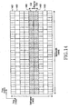
- FIG. 14 illustrates a structure of a sub-frame including the second pilot additionally used for the CQI according to an embodiment of the present invention.
- the horizontal axis corresponds to the frequency domain 1401
- the vertical axis corresponds to the time domain 1402.
- the range of the frequency domain 1401 corresponds to the entire frequency band 1404, and the range of the time domain 1402 corresponds to one sub-frame 1403.
- short blocks 1405 and 1406 carry the first pilots for uplink data
- long blocks 1407 carry the uplink data and control information defining the transform format of the uplink data.
- the CQI is transmitted through a separate resource (CQI resource) 1408 that is temporally discriminated from the resource (data resource) for the uplink data.
- the second pilot for estimation of the channel in relation to the CQI is transmitted to a time resource 1409 just adjacent to the CQI resource 1408, thereby reflecting the channel status of the CQI. Due to the use of the CQI and the second pilot, one sub-frame may have five or less long blocks.
- the CQI and the second pilot are transmitted by a sub-carrier set including a part of the sub-carriers in the entire frequency band 1404, and the CQI and the second pilot are carried by the same sub-carrier(s).
- the second pilot is transmitted according to a distributed transmission scheme, so as to inform the node B of the uplink channel quality for the UE.
- the distributed transmission scheme it is possible to additionally obtain a frequency diversity effect.
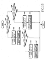
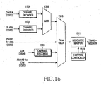
- FIG. 15 is a block diagram illustrating a structure of a transmitter (UE) for time multiplexing data and CQI according to an embodiment of the present invention.
- the uplink data 1502 and the control information 1501 defining the transmit format of the uplink data 1502 are input to channel encoders 1506 and 1507, and are then input to and multiplexed by a multiplexer 1508.
- the output of the multiplexer 1508 is input to a time multiplexer 1510.
- a first pilot 1503 for the uplink data 1502 and/or the control information 1501 is input to the time multiplexer 1510.
- the CQI 1504 When there is CQI 1504 transmitted by the UE for downlink scheduling, the CQI 1504 is subjected to encoding, such as repetition encoding, by a channel encoder 1509, and is then input to the time multiplexer 1510. A second pilot for the CQI 1504 is also input to the time multiplexer 1510.
- the time multiplexer 1510 time-multiplexes the four inputs according to a predetermined sub-frame structure (for example, the structure shown in FIG. 14), and a resource mapper 1511 then transmits the multiplexed information after mapping the multiplexed information to a predetermined resource.
- a resource mapper 1511 transmits the multiplexed information after mapping the multiplexed information to a predetermined resource.
- the resource mapper 1511 the CQI 1504 and the second pilot 1505 are mapped to the same sub-carrier (or sub-carrier group).
- the CQI 1504 and the second pilot 1505 are mapped to a sub-carrier (or sub-carrier group), which changes according to time by determination of a hopping controller 1513.
- the frequency hopping as described above is also applied to the second pilot, and the UE can inform the node B of the uplink channel quality in more detail by the frequency hopping of the second pilot 1505.
- the frequency hopping may be performed according to a time function as defined by Equation (1) below.
- SC - ⁇ i F frame_num ⁇ sub_frame_num ⁇ symbol_num ⁇ Seed
- SC _i denotes an index of a sub-carrier set to which the CQI and the second pilot are mapped
- frame_num denotes a frame number
- sub_frame_num denotes a sub-frame number within the frame
- symbol _ num denotes a symbol number within the sub-frame
- Seed denotes a predetermined reference value.
- F() denotes a predetermined function in the system.
- the resource mapper 1511 includes an FFT (or DFT) block, a sub-carrier mapper, and an IFFT block, as described above with reference to FIG. 2, and the outputs (frequency components) of the resource mapper 1511 are transmitted while maintaining equal intervals (0 or above) between them in the frequency domain.
- FFT or DFT
- FIG. 16 illustrates a structure of a receiver (node B) for receiving and decoding a radio signal transmitted by the transmitter.
- the received signal is time demultiplexed by a time demultiplexer 1602 according to a predetermined sub-frame structure (for example, the structure shown in FIG. 14).
- the time demultiplexer 1602 performs an operation inverse to the operation of the resource mapper 1511 of the transmitter.
- the outputs of the time demultiplexer 1602 include data-related signal 1603, a first pilot 1604 for uplink data, CQI-related signal 1606, and a second pilot 1607 for the CQI.
- the time demultiplexer 1602 performs frequency hopping for the CQI 1606 and the second pilot 1607, and the hopping controller 1617 controls the time demultiplexer 1602. That is, the time demultiplexer 1602 detects a sub-carrier group determined at each transmission time point by the hopping controller 1617, and detects the CQI-related signal 1606 and the second pilot 1607 from the detected sub-carrier group.
- the channel estimator/compensator 1605 performs channel estimation for the data resource by means of the first pilot 1604, and channel-compensates the data-related signal 1603 by means of the channel estimation information.
- the output of the channel estimator/compensator 1605 is demultiplexed into encoded control information and encoded uplink data by the demultiplexer 1610.
- the encoded control information and the encoded uplink data are restored to the uplink data 1614 and the control information 1613 by the channel decoders 1611 and 1612.
- the channel estimator/compensator 1608 performs channel estimation for the CQI resource and then performs channel compensation of the CQI-related signal 1606 by using the channel estimation information.
- the output of the channel estimator 1608 is decoded by a channel decoder 1615, so that it is restored to the CQI 1616.
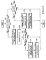
- FIG. 17 is a flow diagram illustrating the operation of a transmitter according to an embodiment of the present invention.
- description of the control information for the uplink data is omitted because it is the same as that of the uplink data.
- the UE determines whether to transmit data in step 1702. Specifically, the UE determines if the UE has data to be transmitted and if there is a data resource allocated to the UE through scheduling, etc. of a node B.
- the UE in step 1703 transmits the data after mapping the data to a data resource (1407 in FIG. 14), which corresponds to the first time interval of one sub-frame, , and then in step 1705 transmits a first pilot for the data after mapping the first pilot to a time resource (1405 and 1406 in FIG. 14) adjacent to the first time interval.
- the UE After transmitting the first pilot, the UE determines in step 1706 if it will transmit CQI for downlink data, based on a predetermined CQI period. If the determination in step 1706 concludes that there is CQI to be transmitted, the UE in step 1707 transmits the CQI after mapping the CQI to a CQI resource (1408 in FIG. 14), which corresponds to a second time interval different from the first time interval, and in step 1708 transmits the second pilot for the CQI after mapping the second pilot to a time resource (1409 in FIG 14) adjacent to the second time interval. If the determination in step 1706 concludes that there is no CQI to be transmitted, no information is transmitted in the second time interval at all.
- the UE in step 1709 determines in step 1704 if there is CQI to be transmitted.
- the UE transmits the CQI in the second time interval and in step 1710 transmits the second pilot for the CQI through the time resource adjacent to the second time interval. In this case, no information is transmitted in the first time interval at all.
- the operation for the current sub-frame is terminated.
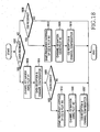
- FIG. 18 is a flow diagram of an operation of a receiver according to an embodiment of the present invention.
- a description of the control information for the uplink data is omitted because it is the same as that of the uplink data.
- the node B determines if there is data to receive in step 1802. Specifically, the node B determines if the node B has allocated a data resource to the UE through scheduling, etc.
- the node B in step 1803 extracts the first pilot from a predetermined time resource block (1405 and 1406 in FIG. 14) of a received signal during one sub-frame and performs channel estimation of the data resource (the first time interval, 1407 in FIG. 14) included in the received signal by using the first pilot.
- the node B extracts data-related signal corresponding to the first time interval of the received signal, and obtains the data by channel-compensating the data-related signal by using channel estimation information obtained based on the first pilot.
- the node B determines in step 1805 if the received signal includes CQI, according to the predetermined CQI period.
- the node B in step 1812 determines the position of the frequency resource for reading the CQI and the second pilot through frequency hopping of the CQI and the second pilot, and extracts the second pilot from a predetermined time resource block (1409 in FIG. 14) of the determined frequency domain and in step 1806 performs channel estimation of the CQI resource (that is, the second time interval 1408 in FIG. 14) of the received signal by using the second pilot.
- the node B recognizes the uplink channel quality from the second pilot and uses the information of uplink channel quality in uplink scheduling. That is, the node B can determine the reception reliability of the CQI based on the channel quality of the CQI resource, can determine the uplink channel quality from the reception reliability of the CQI, and can use the uplink channel quality in uplink scheduling.
- the node B extracts CQI-related signal from the second time interval of the received signal, and channel-compensates the extracted CQI-related signal by using the CQI-related signal obtained from the second pilot, thereby obtaining the CQI.
- the CQI can be used in uplink scheduling.
- the node B determines in step 1808 if there is CQI to receive.
- the node B in step 1813 determines the position of the frequency resource for reading the CQI and the second pilot through frequency hopping of the CQI and the second pilot, and extracts the second pilot from a predetermined time resource block of the determined frequency domain and in step 1809 performs channel estimation of the CQI resource (that is, the second time interval) of the received signal by using the second pilot.
- the node B extracts CQI-related signal from the second time interval of the received signal, and channel-compensates the extracted CQI-related signal by using the CQI-related signal obtained from the second pilot, thereby obtaining the CQI.
- the present invention presents schemes for multiplexing and resource mapping of uplink data and uplink signaling information, in order to satisfy the single sub-carrier characteristic in transmission of the uplink data and uplink signaling information in a Single Carrier Frequency Division Multiple Access (SC-FDMA) wireless communication system.
- SC-FDMA Single Carrier Frequency Division Multiple Access
- the present invention provides a time multiplexing scheme and a pilot structure thereof, which can eliminate factors disturbing the single carrier transmission requirement and prevent PAPR increase, which may occur when uplink data and uplink signaling information such as ACK/NACK and CQI are transmitted without relation to each other. Further, the present invention provides a scheme for frequency hopping of the uplink control information and the pilot, in order to enhance the performance of the channel estimation by using an additional pilot.
Applications Claiming Priority (2)
| Application Number | Priority Date | Filing Date | Title |
|---|---|---|---|
| KR20060002192 | 2006-01-09 | ||
| KR1020060031632A KR100918729B1 (ko) | 2006-01-09 | 2006-04-06 | 단반송파 주파수 분할 다중 접속 시스템에서 역방향 제어정보와 데이터의 시간적 다중화 방법 및 장치 |
Publications (1)
| Publication Number | Publication Date |
|---|---|
| EP1806867A2 true EP1806867A2 (fr) | 2007-07-11 |
Family
ID=38016420
Family Applications (1)
| Application Number | Title | Priority Date | Filing Date |
|---|---|---|---|
| EP07000358A Withdrawn EP1806867A2 (fr) | 2006-01-09 | 2007-01-09 | Procédé et appareil de multiplexage temporel de données sortantes et d'informations de signalisation sortantes dans un système SC-FDMA |
Country Status (3)
| Country | Link |
|---|---|
| US (1) | US20070211656A1 (fr) |
| EP (1) | EP1806867A2 (fr) |
| WO (1) | WO2007081145A1 (fr) |
Cited By (8)
| Publication number | Priority date | Publication date | Assignee | Title |
|---|---|---|---|---|
| EP2001184A2 (fr) * | 2007-06-08 | 2008-12-10 | Samsung Electronics Co., Ltd. | Signalisation de données de contrôle dans des systèmes de communication SC-FDMA |
| EP2037616A2 (fr) * | 2007-09-13 | 2009-03-18 | LG Electronics Inc. | Procédé de transmission de signaux d'accusé de réception de liaison montante |
| EP2084835A1 (fr) * | 2006-11-01 | 2009-08-05 | LG Electronics Inc. | Procédé d'attribution de pilotes |
| US8467367B2 (en) | 2007-08-06 | 2013-06-18 | Qualcomm Incorporated | Multiplexing and transmission of traffic data and control information in a wireless communication system |
| RU2500071C1 (ru) * | 2009-10-19 | 2013-11-27 | Самсунг Электроникс Ко., Лтд. | Мультиплексирование и разнесение передачи для сигналов harq-ack в системах связи |
| EP2075948A3 (fr) * | 2007-12-28 | 2014-05-21 | Fujitsu Limited | Multiplexage de signaux de contrôle |
| CN105471564A (zh) * | 2009-02-24 | 2016-04-06 | 高通股份有限公司 | 灵活的数据和控制复用 |
| EP3208959A1 (fr) * | 2007-02-15 | 2017-08-23 | NTT DoCoMo, Inc. | Appareil de station de base, station mobile, système de communication radio et procédé de commande de communication |
Families Citing this family (33)
| Publication number | Priority date | Publication date | Assignee | Title |
|---|---|---|---|---|
| US8549638B2 (en) * | 2004-06-14 | 2013-10-01 | Fireeye, Inc. | System and method of containing computer worms |
| WO2008066349A1 (fr) | 2006-12-01 | 2008-06-05 | Electronics And Telecommunications Research Institute | Procédé et appareil d'émission / de réception de multiples mots-codes dans un système amrf à porteuse unique |
| KR100874264B1 (ko) | 2006-12-01 | 2008-12-16 | 한국전자통신연구원 | Sc-fdma 시스템에서의 다중 코드 워드 송수신 방법및 장치 |
| US9072095B2 (en) * | 2007-01-09 | 2015-06-30 | Samsung Electronics Co., Ltd. | Apparatus and method for allocating resources in a single carrier-frequency division multiple access system |
| US8953562B2 (en) * | 2007-02-01 | 2015-02-10 | Alcatel Lucent | Method of using uplink reference signals for access grant requests |
| JP4927959B2 (ja) | 2007-03-19 | 2012-05-09 | テレフオンアクチーボラゲット エル エム エリクソン(パブル) | 第1又は第2のタイプのcqiレポートのトリガとしてのアップリンクグラントの利用 |
| JP4563417B2 (ja) * | 2007-03-20 | 2010-10-13 | 株式会社エヌ・ティ・ティ・ドコモ | 移動通信システムにおけるユーザ装置、通信方法及び通信システム |
| US8165228B2 (en) * | 2007-03-20 | 2012-04-24 | Alcatel Lucent | Non-coherent transmission method for uplink control signals using a constant amplitude zero-autocorrelation sequence |
| JP5042320B2 (ja) | 2007-03-29 | 2012-10-03 | エルジー エレクトロニクス インコーポレイティド | 無線通信システムにおけるサウンディング基準信号伝送方法 |
| CN101299871B (zh) * | 2007-04-30 | 2012-07-25 | 电信科学技术研究院 | 发送上行探测导频的方法及系统、基站和终端 |
| KR101380558B1 (ko) | 2007-06-19 | 2014-04-02 | 엘지전자 주식회사 | 사운딩 기준신호의 전송방법 |
| KR20090006708A (ko) | 2007-07-12 | 2009-01-15 | 엘지전자 주식회사 | 스케줄링 요청 신호 전송 방법 |
| EP2176965B1 (fr) * | 2007-07-16 | 2018-09-05 | Samsung Electronics Co., Ltd. | Appareil et procédé de transmission d'un indicateur de qualité de canal et de signaux d'acquittement dans des systèmes de communication sc-fdma |
| RU2433541C2 (ru) * | 2007-07-16 | 2011-11-10 | Самсунг Электроникс Ко., Лтд. | Устройство и способ для передачи сигналов индикатора качества канала и подтверждения приема в системах связи sc-fdma |
| KR101397039B1 (ko) * | 2007-08-14 | 2014-05-20 | 엘지전자 주식회사 | 전송 다이버시티를 사용하는 다중안테나 시스템에서 채널예측 오류의 영향을 감소시키기 위한 cdm 방식 신호전송 방법 |
| RU2439809C2 (ru) | 2007-08-14 | 2012-01-10 | Эл Джи Электроникс Инк. | Способ получения информации об области ресурсов для канала phich и способ приема канала pdcch |
| KR101430267B1 (ko) * | 2007-08-14 | 2014-08-18 | 엘지전자 주식회사 | 무선통신시스템에서의 데이터 전송방법 |
| KR101507785B1 (ko) | 2007-08-16 | 2015-04-03 | 엘지전자 주식회사 | 다중 입출력 시스템에서, 채널품질정보를 송신하는 방법 |
| KR101405974B1 (ko) | 2007-08-16 | 2014-06-27 | 엘지전자 주식회사 | 다중입력 다중출력 시스템에서 코드워드를 전송하는 방법 |
| US9507669B2 (en) * | 2007-11-15 | 2016-11-29 | Lg Electronics Inc. | Method of transmitting data using HARQ |
| US8335165B2 (en) * | 2008-03-04 | 2012-12-18 | Texas Instruments Incorporated | Transmission of multiple ACK/NAK bits with data |
| US7990919B2 (en) | 2008-03-20 | 2011-08-02 | Apple Inc. | Techniques for reducing communication errors in a wireless communication system |
| KR101260814B1 (ko) * | 2009-03-17 | 2013-05-06 | 닛본 덴끼 가부시끼가이샤 | 무선 기지국 장치, 무선 통신 시스템, 무선 통신 방법, 및 프로그램 |
| WO2010140826A2 (fr) * | 2009-06-03 | 2010-12-09 | Samsung Electronics Co., Ltd. | Application sélective de saut de fréquence pour transmission de signaux de commande |
| EP2595333B1 (fr) | 2010-07-16 | 2018-11-28 | LG Electronics Inc. | Procédé d'envoi d'informations de commande et appareil associé |
| US8842535B2 (en) * | 2010-08-03 | 2014-09-23 | Apple Inc. | Method and apparatus for radio link control during network congestion in a mobile wireless device |
| KR101855523B1 (ko) * | 2011-10-06 | 2018-05-04 | 삼성전자주식회사 | 통신 시스템에서 피드백 생성 방법 및 장치 |
| US9936519B2 (en) | 2015-03-15 | 2018-04-03 | Qualcomm Incorporated | Self-contained time division duplex (TDD) subframe structure for wireless communications |
| US10075970B2 (en) | 2015-03-15 | 2018-09-11 | Qualcomm Incorporated | Mission critical data support in self-contained time division duplex (TDD) subframe structure |
| US9814058B2 (en) | 2015-05-15 | 2017-11-07 | Qualcomm Incorporated | Scaled symbols for a self-contained time division duplex (TDD) subframe structure |
| US9992790B2 (en) | 2015-07-20 | 2018-06-05 | Qualcomm Incorporated | Time division duplex (TDD) subframe structure supporting single and multiple interlace modes |
| ES2753219T3 (es) | 2016-04-07 | 2020-04-07 | Ericsson Telefon Ab L M | Nodo de red de radio, dispositivo inalámbrico y métodos llevados a cabo en los mismos |
| WO2020226386A1 (fr) * | 2019-05-03 | 2020-11-12 | 엘지전자 주식회사 | Procédé de transmission de signal de liaison latérale dans un système de communication sans fil |
Family Cites Families (7)
| Publication number | Priority date | Publication date | Assignee | Title |
|---|---|---|---|---|
| WO2001041343A1 (fr) * | 1999-12-02 | 2001-06-07 | Samsung Electronics Co., Ltd | Appareil et procede de transmission et de reception de donnees dans un systeme de communication amdc |
| CN1264289C (zh) * | 2001-11-19 | 2006-07-12 | 三星电子株式会社 | Cdma通信系统中上行链路传输功率控制的方法和设备 |
| US7039001B2 (en) * | 2002-10-29 | 2006-05-02 | Qualcomm, Incorporated | Channel estimation for OFDM communication systems |
| US7961700B2 (en) * | 2005-04-28 | 2011-06-14 | Qualcomm Incorporated | Multi-carrier operation in data transmission systems |
| US8885628B2 (en) * | 2005-08-08 | 2014-11-11 | Qualcomm Incorporated | Code division multiplexing in a single-carrier frequency division multiple access system |
| US7903628B2 (en) * | 2005-08-22 | 2011-03-08 | Qualcomm Incorporated | Configurable pilots in a wireless communication system |
| US20070047495A1 (en) * | 2005-08-29 | 2007-03-01 | Qualcomm Incorporated | Reverse link soft handoff in a wireless multiple-access communication system |
-
2007
- 2007-01-09 US US11/651,207 patent/US20070211656A1/en not_active Abandoned
- 2007-01-09 WO PCT/KR2007/000156 patent/WO2007081145A1/fr active Application Filing
- 2007-01-09 EP EP07000358A patent/EP1806867A2/fr not_active Withdrawn
Cited By (38)
| Publication number | Priority date | Publication date | Assignee | Title |
|---|---|---|---|---|
| EP3496312A1 (fr) * | 2006-11-01 | 2019-06-12 | LG Electronics Inc. | Procédé d'attribution de pilotes |
| US9386561B2 (en) | 2006-11-01 | 2016-07-05 | Lg Electronics Inc. | Method for allocating pilots |
| EP2084835A1 (fr) * | 2006-11-01 | 2009-08-05 | LG Electronics Inc. | Procédé d'attribution de pilotes |
| EP2084835A4 (fr) * | 2006-11-01 | 2014-05-21 | Lg Electronics Inc | Procédé d'attribution de pilotes |
| EP3208959A1 (fr) * | 2007-02-15 | 2017-08-23 | NTT DoCoMo, Inc. | Appareil de station de base, station mobile, système de communication radio et procédé de commande de communication |
| US10038539B2 (en) | 2007-06-08 | 2018-07-31 | Samsung Electronics Co., Ltd | Control and data signaling in SC-FDMA communication systems |
| EP2001184A3 (fr) * | 2007-06-08 | 2014-02-19 | Samsung Electronics Co., Ltd. | Signalisation de données de contrôle dans des systèmes de communication SC-FDMA |
| US10700840B2 (en) | 2007-06-08 | 2020-06-30 | Samsung Electronics Co., Ltd | Control and data signaling in SC-FDMA communication systems |
| US11431458B2 (en) | 2007-06-08 | 2022-08-30 | Samsung Electronics Co., Ltd | Control and data signaling in SC-FDMA communication systems |
| US8761130B2 (en) | 2007-06-08 | 2014-06-24 | Samsung Electronics Co., Ltd | Control and data signaling in SC-FDMA communication systems |
| EP2001184A2 (fr) * | 2007-06-08 | 2008-12-10 | Samsung Electronics Co., Ltd. | Signalisation de données de contrôle dans des systèmes de communication SC-FDMA |
| US10003447B2 (en) | 2007-06-08 | 2018-06-19 | Samsung Electronics Co., Ltd | Control and data signaling in SC-FDMA communication systems |
| US9300454B2 (en) | 2007-06-08 | 2016-03-29 | Samsung Electronics Co., Ltd | Control and data signaling in SC-FDMA communication systems |
| US9973316B2 (en) | 2007-06-08 | 2018-05-15 | Samsuing Electronics Co., Ltd | Control and data signaling in SC-FDMA communication systems |
| US11929955B2 (en) | 2007-06-08 | 2024-03-12 | Samsung Electronics Co., Ltd | Control and data signaling in SC-FDMA communication systems |
| US8467367B2 (en) | 2007-08-06 | 2013-06-18 | Qualcomm Incorporated | Multiplexing and transmission of traffic data and control information in a wireless communication system |
| TWI452881B (zh) * | 2007-08-06 | 2014-09-11 | Qualcomm Inc | 於無線通信系統中流量資料與控制資訊的多工及傳輸 |
| US9306795B2 (en) | 2007-08-06 | 2016-04-05 | Qualcomm Incorporated | Multiplexing and transmission of traffic data and control information in a wireless communication system |
| JP2018107827A (ja) * | 2007-09-13 | 2018-07-05 | オプティス セルラー テクノロジー, リミテッド・ライアビリティ・カンパニー | 上りリンク信号の伝送方法 |
| US9001814B2 (en) | 2007-09-13 | 2015-04-07 | Optis Cellular Technology, Llc | Method for transmitting uplink signals |
| EP2037616A2 (fr) * | 2007-09-13 | 2009-03-18 | LG Electronics Inc. | Procédé de transmission de signaux d'accusé de réception de liaison montante |
| JP2017112623A (ja) * | 2007-09-13 | 2017-06-22 | オプティス セルラー テクノロジー, リミテッド・ライアビリティ・カンパニー | 上りリンク信号の伝送方法 |
| EP4156576A1 (fr) * | 2007-09-13 | 2023-03-29 | Optis Cellular Technology, LLC | Procédé de transmission de signaux de liaison montante |
| EP2723011A3 (fr) * | 2007-09-13 | 2017-11-01 | Optis Cellular Technology, LLC | Procédé de transmission de signaux de liaison montante |
| EP2037616A3 (fr) * | 2007-09-13 | 2011-04-13 | LG Electronics Inc. | Procédé de transmission de signaux d'accusé de réception de liaison montante |
| US11012222B2 (en) | 2007-09-13 | 2021-05-18 | Optis Cellular Technology, Llc | Method for transmitting uplink signals |
| EP3739786A1 (fr) * | 2007-09-13 | 2020-11-18 | Optis Cellular Technology, LLC | Procédé de transmission de signaux de liaison montante |
| US8102833B2 (en) | 2007-09-13 | 2012-01-24 | Lg Electroics Inc. | Method for transmitting uplink signals |
| JP2020005269A (ja) * | 2007-09-13 | 2020-01-09 | オプティス セルラー テクノロジー, リミテッド・ライアビリティ・カンパニー | 上りリンク信号の伝送方法 |
| US10374775B2 (en) | 2007-09-13 | 2019-08-06 | Optis Cellular Technology, Llc | Method for transmitting uplink signals |
| EP2075948A3 (fr) * | 2007-12-28 | 2014-05-21 | Fujitsu Limited | Multiplexage de signaux de contrôle |
| US9497735B2 (en) | 2007-12-28 | 2016-11-15 | Fujitsu Limited | Method of signal multiplexing and transmitter in radio communication system |
| CN105471564A (zh) * | 2009-02-24 | 2016-04-06 | 高通股份有限公司 | 灵活的数据和控制复用 |
| RU2500071C1 (ru) * | 2009-10-19 | 2013-11-27 | Самсунг Электроникс Ко., Лтд. | Мультиплексирование и разнесение передачи для сигналов harq-ack в системах связи |
| US9444603B2 (en) | 2009-10-19 | 2016-09-13 | Samsung Electronics Co., Ltd | Transmission diversity and multiplexing for HARQ-ACK signals in communication systems |
| RU2568322C2 (ru) * | 2009-10-19 | 2015-11-20 | Самсунг Электроникс Ко., Лтд. | Мультиплексирование и разнесение передачи для сигналов harq-ack в системах связи |
| US9992006B2 (en) | 2009-10-19 | 2018-06-05 | Samsung Electronics Co., Ltd | Transmission diversity and multiplexing for HARQ-ACK signals in communication systems |
| US9438402B2 (en) | 2009-10-19 | 2016-09-06 | Samsung Electronics Co., Ltd | Transmission diversity and multiplexing for HARQ-ACK signals in communication systems |
Also Published As
| Publication number | Publication date |
|---|---|
| WO2007081145A1 (fr) | 2007-07-19 |
| US20070211656A1 (en) | 2007-09-13 |
Similar Documents
| Publication | Publication Date | Title |
|---|---|---|
| EP1806867A2 (fr) | Procédé et appareil de multiplexage temporel de données sortantes et d'informations de signalisation sortantes dans un système SC-FDMA | |
| US11096160B2 (en) | Multiplexing large payloads of control information from user equipments | |
| US10958400B2 (en) | Method and apparatus for transmitting/receiving uplink signaling information in a single carrier FDMA system | |
| US10348473B2 (en) | Method and apparatus for transmitting/receiving uplink signaling information in a single carrier FDMA system | |
| KR100918729B1 (ko) | 단반송파 주파수 분할 다중 접속 시스템에서 역방향 제어정보와 데이터의 시간적 다중화 방법 및 장치 | |
| US10686579B2 (en) | Partial CQI feedback in wireless networks | |
| EP2176965B1 (fr) | Appareil et procédé de transmission d'un indicateur de qualité de canal et de signaux d'acquittement dans des systèmes de communication sc-fdma | |
| JP5665240B2 (ja) | データチャンネル又は制御チャンネルを通じるアップリンク制御情報の送信 | |
| EP2437561B1 (fr) | Système de communication mobile, appareil de station de base, appareil de station mobile et procédé de communication mobile | |
| EP2176964B1 (fr) | Appareil et procédé de transmission de canaux de controle de liaison montante dans un système de communication sans fil | |
| US8705457B2 (en) | Apparatus and method for transmitting control channel for frequency resource allocation in a wireless communication system | |
| US20150055643A1 (en) | Apparatus and method for transmitting channel quality indicator and acknowledgement signals in sc-fdma communication systems | |
| US8520654B2 (en) | Method and apparatus for allocating and identifying frequency resources in a frequency division multiple access system | |
| WO2008084927A1 (fr) | Procédé et appareil pour transmettre/recevoir un signal d'accusé de reception/accusé de réception négatif (ack/nack) dans un système de communication mobile | |
| US8891470B2 (en) | Method and apparatus for feedback transmission in a wireless communication system | |
| KR20080088127A (ko) | 하이브리드 자동 재전송 요구 및 다중 안테나 기법을사용하는 무선 통신 시스템에서 비동기 긍정적/부정적 인지검파를 사용하는 상향 링크 긍정적/부정적 인지 채널 자원할당을 위한 암시적 시그널링 장치 및 방법 | |
| WO2011099779A2 (fr) | Procédé et appareil destinés à une transmission de rétroaction dans un système de communication sans fil | |
| KR20080099211A (ko) | Ofdma 시스템에서의 맵 시그널링 방법 | |
| KR20070094426A (ko) | 다수의 부 반송파를 이용하는 통신 시스템에 있어서, 전송제어 방법 및 장치 |
Legal Events
| Date | Code | Title | Description |
|---|---|---|---|
| PUAI | Public reference made under article 153(3) epc to a published international application that has entered the european phase |
Free format text: ORIGINAL CODE: 0009012 |
|
| 17P | Request for examination filed |
Effective date: 20070109 |
|
| AK | Designated contracting states |
Kind code of ref document: A2 Designated state(s): AT BE BG CH CY CZ DE DK EE ES FI FR GB GR HU IE IS IT LI LT LU LV MC NL PL PT RO SE SI SK TR |
|
| AX | Request for extension of the european patent |
Extension state: AL BA HR MK YU |
|
| STAA | Information on the status of an ep patent application or granted ep patent |
Free format text: STATUS: THE APPLICATION HAS BEEN WITHDRAWN |
|
| 18W | Application withdrawn |
Effective date: 20091105 |