EP1806545A2 - Collecteur solaire destiné au réchauffement de lýeau pour une piscine et kit approprié - Google Patents
Collecteur solaire destiné au réchauffement de lýeau pour une piscine et kit approprié Download PDFInfo
- Publication number
- EP1806545A2 EP1806545A2 EP06126060A EP06126060A EP1806545A2 EP 1806545 A2 EP1806545 A2 EP 1806545A2 EP 06126060 A EP06126060 A EP 06126060A EP 06126060 A EP06126060 A EP 06126060A EP 1806545 A2 EP1806545 A2 EP 1806545A2
- Authority
- EP
- European Patent Office
- Prior art keywords
- solar collector
- shut
- line
- collector according
- supply line
- Prior art date
- Legal status (The legal status is an assumption and is not a legal conclusion. Google has not performed a legal analysis and makes no representation as to the accuracy of the status listed.)
- Withdrawn
Links
Images

Classifications
-
- F—MECHANICAL ENGINEERING; LIGHTING; HEATING; WEAPONS; BLASTING
- F24—HEATING; RANGES; VENTILATING
- F24S—SOLAR HEAT COLLECTORS; SOLAR HEAT SYSTEMS
- F24S10/00—Solar heat collectors using working fluids
- F24S10/70—Solar heat collectors using working fluids the working fluids being conveyed through tubular absorbing conduits
- F24S10/74—Solar heat collectors using working fluids the working fluids being conveyed through tubular absorbing conduits the tubular conduits are not fixed to heat absorbing plates and are not touching each other
- F24S10/742—Solar heat collectors using working fluids the working fluids being conveyed through tubular absorbing conduits the tubular conduits are not fixed to heat absorbing plates and are not touching each other the conduits being parallel to each other
-
- F—MECHANICAL ENGINEERING; LIGHTING; HEATING; WEAPONS; BLASTING
- F24—HEATING; RANGES; VENTILATING
- F24S—SOLAR HEAT COLLECTORS; SOLAR HEAT SYSTEMS
- F24S10/00—Solar heat collectors using working fluids
- F24S10/70—Solar heat collectors using working fluids the working fluids being conveyed through tubular absorbing conduits
- F24S10/73—Solar heat collectors using working fluids the working fluids being conveyed through tubular absorbing conduits the tubular conduits being of plastic material
-
- F—MECHANICAL ENGINEERING; LIGHTING; HEATING; WEAPONS; BLASTING
- F24—HEATING; RANGES; VENTILATING
- F24S—SOLAR HEAT COLLECTORS; SOLAR HEAT SYSTEMS
- F24S20/00—Solar heat collectors specially adapted for particular uses or environments
- F24S20/02—Solar heat collectors specially adapted for particular uses or environments for swimming pools
-
- F—MECHANICAL ENGINEERING; LIGHTING; HEATING; WEAPONS; BLASTING
- F24—HEATING; RANGES; VENTILATING
- F24S—SOLAR HEAT COLLECTORS; SOLAR HEAT SYSTEMS
- F24S40/00—Safety or protection arrangements of solar heat collectors; Preventing malfunction of solar heat collectors
- F24S40/50—Preventing overheating or overpressure
-
- F—MECHANICAL ENGINEERING; LIGHTING; HEATING; WEAPONS; BLASTING
- F24—HEATING; RANGES; VENTILATING
- F24S—SOLAR HEAT COLLECTORS; SOLAR HEAT SYSTEMS
- F24S50/00—Arrangements for controlling solar heat collectors
- F24S50/40—Arrangements for controlling solar heat collectors responsive to temperature
-
- F—MECHANICAL ENGINEERING; LIGHTING; HEATING; WEAPONS; BLASTING
- F24—HEATING; RANGES; VENTILATING
- F24S—SOLAR HEAT COLLECTORS; SOLAR HEAT SYSTEMS
- F24S80/00—Details, accessories or component parts of solar heat collectors not provided for in groups F24S10/00-F24S70/00
- F24S80/30—Arrangements for connecting the fluid circuits of solar collectors with each other or with other components, e.g. pipe connections; Fluid distributing means, e.g. headers
-
- Y—GENERAL TAGGING OF NEW TECHNOLOGICAL DEVELOPMENTS; GENERAL TAGGING OF CROSS-SECTIONAL TECHNOLOGIES SPANNING OVER SEVERAL SECTIONS OF THE IPC; TECHNICAL SUBJECTS COVERED BY FORMER USPC CROSS-REFERENCE ART COLLECTIONS [XRACs] AND DIGESTS
- Y02—TECHNOLOGIES OR APPLICATIONS FOR MITIGATION OR ADAPTATION AGAINST CLIMATE CHANGE
- Y02E—REDUCTION OF GREENHOUSE GAS [GHG] EMISSIONS, RELATED TO ENERGY GENERATION, TRANSMISSION OR DISTRIBUTION
- Y02E10/00—Energy generation through renewable energy sources
- Y02E10/40—Solar thermal energy, e.g. solar towers
- Y02E10/44—Heat exchange systems
Definitions
- the present invention relates to a solar collector for heating water for a swimming pool, comprising a mat-shaped tube arrangement which is formed by a plurality of mutually parallel tubes, which are assigned to either an inlet section or a return section for the water to be heated, which associated with the inlet section Tubes are connected to a common, extending at a head side of the tube assembly manifold supply line, and the tubes associated with the return portion open at the same head side of the tube assembly in a common collection discharge leading to an outlet opening.
- the invention relates to a kit for the production of a solar collector, which comprises a plastic tubing string for producing a mat-shaped tube arrangement, a distributor feed line and a collecting outlet.
- Such flat panels are used for heating the bath water permanently installed or freely deployable swimming pools or children's pools indoors or outdoors.
- the known collectors have an absorber tube arrangement through which the bath water to be heated flows, by means of which the energy radiated by the sun is continuously transmitted to the water circulating in the tube arrangement and supplied to the swimming pool.
- Electrically operated circulating pumps serve to transport the solar thermal heated water from the collector to the swimming pool.
- To maintain the water quality filters are used by means of which the water running treated and organic and inorganic dirt particles are mechanically removed.
- the tube assembly is mat-shaped formed of numerous parallel metal or plastic tubes, wherein the individual tubes are embedded in a shell material or connected to each other via transverse webs.
- the mutually parallel tubes open on both sides in common distribution lines. Depending on the course of the water flow in the tube arrangement, it is possible to distinguish between “diagonal absorbers” and “reverse absorbers”.
- the water to be heated flows through all the tubes of the absorber mat in the same flow direction.
- a distributor supply line extends over the entire inlet side of the absorber mat.
- the water to be heated enters via this supply line in the tube assembly, distributed approximately uniformly in the tubes and exits on the opposite outlet side via a common manifold-derivation again.
- Inlet and outlet are provided at two diagonally opposite corners of the absorber mat.
- a solar collector of this kind is for example in the DE 202 15 126 U1 described.
- the Aborber mat is divided into at least two (not necessarily equal) sections, namely an inlet and a return section.
- the water to be heated enters via a distributor supply line, which extends only along the inlet section of the absorber mat, in the tubes associated with the inlet section, flows through them in one flow direction, and is connected via a distribution line on the opposite end in the Diverted return passage associated tubes, through which the water flows back in the reverse flow direction to the absorber head side and exits via a collection discharge. Entry and exit are thus on the same side of the mat.
- the water return tubes of the return section replace an otherwise necessary separate return pipe, so that compared to the diagonal absorber results in a lower material and assembly costs.
- Solar collectors based on the principle of the reverse absorber are therefore used primarily for applications in which it is very low cost.
- kits for self-construction of such solar collectors contain in addition to the required semi-finished products for the preparation of the tube assembly and the distribution and manifolds usually also a circulation pump and the required filters.
- the present invention has for its object to optimize a solar collector in terms of further cost savings. Furthermore, the invention has for its object to provide a suitable for the preparation of the solar collector according to the invention, inexpensive kit.
- this object is achieved on the basis of a solar collector of the type mentioned in the present invention, that the distributor supply line and the collection discharge form a leading to the outlet opening shorting line, which is closed by means of a shut-off.
- a direct fluidic connection between the distributor supply line and the collecting derivative is provided.
- This connection forms a short-circuit line leading to the outlet opening, which can be closed and opened again by means of a movable shut-off element if required.
- a continuous or at least temporary circulation of the bath water is appropriate for removing contaminants through the filter and thus for maintaining the water quality.
- the continuous circulation operation via the tube arrangement of the solar collector can contribute to a cooling of the bath water, which is generally undesirable.
- a high ambient temperature or a strong sunlight during continuous circulation operation with the inclusion of the tube arrangement can lead to excessive heating of the bath water.
- connection which is referred to here and hereinafter as a "short-circuit line"
- a shut-off element can be closed by means of a shut-off element and opened, wherein it fulfills the purpose of a bypass for the tube arrangement in the opened state.
- the distributor supply line and the collection outlet are closed on one side, so that the water to be heated flows into the tube arrangement. They can thereby - for example, separated from each other by a partition - be formed in a common pipe section.
- simple measures namely the preparation of a fluidly sealed connection between these lines (manifold inlet and collective discharge) and the possibility of this line close by means of a shut-off and open when needed ..
- the shut-off element engages in the area between distributor supply line and collective discharge, for example on a possible separate connection line between distributor supply line and collective discharge line.
- a completely or sectionally elastically deformable connection line can be closed, for example, by compression by means of a shut-off element in the form of a clamp or the like.
- the shut-off element is a component inserted into the short-circuit line is preferred.
- the shut-off element is in this case, on the one hand, directly or indirectly connected to the distributor supply line and, on the other hand, directly or indirectly connected to the collection discharge line.
- Appropriate designs include valves, taps or valves.
- distributor supply line and collection discharge in rigid version the production of a tight connection to the shut-off designed particularly simple. This embodiment is therefore characterized by high reliability and very low installation costs.
- shut-off element is designed as a stopcock.
- the short-circuit line is closed or opened. This can be done electrically or manually, with a hand-operated shut-off for cost reasons is given preference.
- the connecting device serves on the one hand for liquid-tight connection to distributor supply line and collecting discharge and on the other hand for receiving and fixing the shut-off.
- the connecting device comprises a flange connected to the distributor supply line and a flange connected to the collecting outlet, wherein the blocking element is fixed between the opposing flanges.
- the shut-off element is present here as a separate fitting to be inserted by means of a flange connection into the short-circuit line.
- flange connections are also easy to manufacture and seal by laymen.
- the distributor supply line, the collection outlet and the connecting device consist of the same plastic.
- the plastics which are suitable for the production of the distributor feed line, the collecting discharge line and the connecting device are distinguished by high resistance, in particular to UV radiation and to the water to be heated, which may contain corrosive chemicals. Joining joints of said components show each other because of the same thermal expansion coefficient low sealing and aging problems.
- the collecting outlet of the front absorber is usually connected to the distributor inlet of the rear absorber.
- Openable and closable shut-off elements are preferably provided between the distributor supply line and the collection outlet of all connected absorbers.
- the mat-shaped tube assembly comprises two interconnected "diagonal absorber” tube arrangements, it has been found to be useful if one absorber is the distributor inlet and the tubes associated with the inlet section and the other absorber is the collection outlet and forms the tubes associated with the return section.
- the outlet of the one diagonal absorber is connected to the inlet of the other, so that the one diagonal absorber is assigned to the inlet section for the water to be heated, and the other diagonal absorber the return section.
- the short-circuit line is only required between the distributor feed line of the front diagonal absorber and the collective discharge line of the downstream diagonal absorber.
- the shut-off element is connected to a temperature control device.
- the shut-off element is electrically or mechanically variably adjustable depending on a temperature to an opening value between the open position and the closed position, wherein the setting of the opening value is based on a temperature control or control.
- the relevant temperature is, for example, the water temperature at the inlet to the solar collector, the outlet from the solar collector, the ambient temperature or a mixing temperature thereof.
- the temperature setting for example, the maximum or minimum water temperature can be specified at the outlet, above or below the open the short-circuit line and the absorber should not be flowed through.
- This temperature control or control can be done by means of electrically controllable shut-off elements, such as electrical control valves. However, it has proven particularly useful if the temperature control device comprises an expansion body which acts normally on the shut-off element.
- the temperature control or control can be carried out without connecting the shut-off to a power source.
- the use of such expansion body is common for example in thermostats or ventilation devices in greenhouses or conservatories. They consist essentially of a substance having a high coefficient of thermal expansion, which may be present as a solid or as a gas, liquid or gel in suitable encapsulation.
- kit for the solar collector the above object is achieved starting from a kit of the type mentioned in the present invention, that for the formation of a short-circuit line between the distributor supply line and collection derivation a connecting device is provided, and that for closing the short-circuit line, a movable shut-off element is included.
- the kit according to the present invention comprises a connecting device for forming a short-circuit line between the distributor supply line and collecting outlet and a movable shut-off element for closing and opening the short-circuit line.
- the shut-off element is thus movable between an open position and a closed position.
- the connecting device comprises a flange to be connected to the distributor supply line and a flange to be connected to the collecting discharge line.
- the shut-off element is present as a separate fitting which is to be inserted into the short-circuit line by means of the flange connection.
- the flanges are preferably connected to laterally slotted sleeves, which are pushed over the respective line (distributor supply line or collective discharge) and glued to them.
- the side slots are recesses for each adjacent tube.
- the flanges and the sleeve are preferably made of the same material - usually made of plastic - as the said lines.
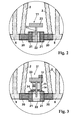
- the solar collector shown in Figure 1 is designed in the form of a reverse absorber.
- the absorber mat 1 consists of a plurality of mutually parallel ribbed tubes 2, which are associated with two approximately equal sized mat sections, namely an inlet section (directional arrow 3) and a return section (directional arrow 4).
- the finned tubes 2 are made of polypropylene, which is resistant to UV radiation and resistant to chlorine-containing water.
- the water to be heated from the circulating pump which is symbolized by the arrow 5
- a distributor feed line 6 which extends along the inlet section 3 of the absorber mat 1, and with that of the inlet section 3 associated finned tubes 2 are connected.
- the water is heated and passes through the distribution line 7 at the opposite end face of the absorber mat 1 in the return pipe 4 associated finned tubes 2, through which the water below further heat absorption flows back in the reverse flow direction, and passes through a collection outlet 8 to the outlet 9, which is connected to the (not shown in the figure) swimming pool.
- the distributor supply line 6 and the collection outlet 8 are closed at the end and in this respect separated from each other.
- an immediate fluidic connection is provided between the distributor supply line 6 and the collecting outlet 8, which serves as a short-circuit line 12 for the finned tubes 2 of the absorber mat 1.
- the short-circuit line 12 is closed by means of a movable shut-off element in the form of a slide 11, wherein the solar collector in the closed position of the short-circuit line 12, as shown schematically in Figure 1, is in its intended normal operating mode.
- a short-circuit line 12 in the open position (as shown in Figure 2)
- the water of the swimming pool is circulated via filter and pump 5 directly through the manifold inlet 6 and the collection outlet 8, the finned tubes 2 depending on the arrangement of the absorber mat here can run empty.
- the mutually facing end faces of distributor supply line 6 and collection discharge 8 are each connected via a sleeve 20 with a flange 21.
- Sleeve 21 and flange 21 are glued together and consist of the same plastic as the lines 6, 8, namely acrylonitrile butadiene styrene (ABS).
- ABS acrylonitrile butadiene styrene
- the components 6, 8, 20 and 21 are injection-molded parts and they have a thickness which ensures a certain flexural rigidity and thus facilitates the production of a permanently watertight connection.
- the sleeves 20 are via distributor supply line 6 and collection discharge 8, respectively pushed and glued to these. At their opposite end of the flange 21, they have a recess for each adjacent, adjacent finned tube.
- the slide 11 comprises a handle 23, which is connected to a closing piston 24 for shutting off the flow of water from the distributor supply line 6 to the collecting outlet 8, and which can also be used as needed to limit or regulate the flow.
- a closing piston 24 When the closing piston 24 is open, as shown in Figure 2, the water flows under the pressure of the circulation pump 5 directly from the distributor supply line 6 to the collection outlet 8 and the outlet 9 back into the swimming pool, so that a continuous cleaning of the water below Bypassing the absorber mat 1 is enabled.
- the kit for the production of the solar collector in DIY includes not only the otherwise provided components such as a tubing for cutting the required fin tubes 2, to be connected to the finned tubes 2 manifolds 6, 7 and 8 and the required connection parts, and the shut-off in shape the slider 11 and the components required for its assembly, so the sleeves 20 and the associated flanges 21st
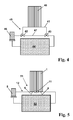
- the embodiment of the shut-off element 31 according to FIG. 3 is additionally equipped with an electroless temperature control.
- an electroless temperature control extends between the handle 23 and the top of the housing 22, a commercially available expansion body 32, the longitudinal extent in the direction of the closing piston (24) -longitudinal axis clearly from the Ambient temperature depends.
- a longer length which leads to a lifting of the handle 23 and the closing piston 24, so that, bypassing the tube assembly 1, a stronger water flow from the distributor supply line 6 sets directly to the collection discharge 8.
- the resulting in the expansion body 32 due to a temperature difference of about 40 ° C length difference corresponds approximately to the necessary stroke for closing and full opening of the short-circuit line 12th
- the temperature control serves to limit the temperature at the outlet 9 in high solar radiation.
- the specification of the maximum temperature is achieved by adjusting the initial length of the expansion body 32.
- a knurled screw 33 is provided, which is attached to the handle 23 and which cooperates via a threaded rod 35 with a bottom plate 34 of the expansion body 32.
- the temperature control by means of an expansion body acting on the shut-off 31 may also be designed so that this opens at decreasing ambient temperature.
- the short-circuit line 12 is opened, so that sets with increasing temperature difference between the ambient temperature and the preset minimum temperature, bypassing the tube assembly 1, a stronger water flow from the distributor supply line 6 directly to the collection outlet 8.
- This temperature control thus serves to bypass the tube assembly 1 at too low ambient temperature.
- FIG. 4 schematically shows a circuit known from the prior art for operating a solar collector.
- a solar collector 45 For heating the bathing water of a swimming pool 44, a solar collector 45 is provided, which comprises a circulation pump 46 with filter device, a tube assembly 40 for heating the water and a Power system includes.
- the power system includes a bypass line 41 in which the tube assembly 40 is disposed and a bypass line 47.
- the water flows through the tube assembly 40 through the bypass conduit 41 and is heated therein. Otherwise, the water flows past the tube assembly 40 via the bypass 47.
- the bypass line 41 is branched off from the bypass line 47 by means of two three-way fittings 42, 34, so that a total of six watertight hose connections are required.
- a solar collector 51 is provided, in which the tube assembly 1 is not inserted into a separate bypass line, but in the short circuit line 12. This is composed of a front portion, which is assigned to the distributor supply line 6 and a rear portion, which is assigned to the collection lead 8 of the tube assembly 1.
- the distributor feed line 6 and the collecting discharge line 8 are fluidically connected to form a short-circuit line 12.
- a shut-off element 11 is provided, by means of which the short-circuit line 12 can be completely or partially closed, as has already been described in detail above.
Landscapes
- Engineering & Computer Science (AREA)
- Physics & Mathematics (AREA)
- Life Sciences & Earth Sciences (AREA)
- Sustainable Development (AREA)
- Sustainable Energy (AREA)
- Thermal Sciences (AREA)
- Chemical & Material Sciences (AREA)
- Combustion & Propulsion (AREA)
- Mechanical Engineering (AREA)
- General Engineering & Computer Science (AREA)
- Steam Or Hot-Water Central Heating Systems (AREA)
Applications Claiming Priority (1)
| Application Number | Priority Date | Filing Date | Title |
|---|---|---|---|
| DE102005061008A DE102005061008B3 (de) | 2005-12-19 | 2005-12-19 | Solarkollektor zum Erwärmen von Wasser für einen Swimmingpool und dafür geeigneter Bausatz |
Publications (1)
| Publication Number | Publication Date |
|---|---|
| EP1806545A2 true EP1806545A2 (fr) | 2007-07-11 |
Family
ID=37832858
Family Applications (1)
| Application Number | Title | Priority Date | Filing Date |
|---|---|---|---|
| EP06126060A Withdrawn EP1806545A2 (fr) | 2005-12-19 | 2006-12-13 | Collecteur solaire destiné au réchauffement de lýeau pour une piscine et kit approprié |
Country Status (2)
| Country | Link |
|---|---|
| EP (1) | EP1806545A2 (fr) |
| DE (1) | DE102005061008B3 (fr) |
Cited By (4)
| Publication number | Priority date | Publication date | Assignee | Title |
|---|---|---|---|---|
| US20110162640A1 (en) * | 2008-06-29 | 2011-07-07 | Shlomo Gabbay | Solar collector |
| EP2381187A3 (fr) * | 2010-04-26 | 2014-01-08 | SCHÜCO International KG | Absorbeur |
| DE102013008717A1 (de) * | 2013-02-07 | 2014-08-07 | Schmöle GmbH | Flächenwärmetauscherelement, Verfahren zur Herstellung eines Flächenwärmetauscherelementes und Werkzeug |
| WO2015042728A1 (fr) | 2013-09-24 | 2015-04-02 | Energen Chile S.A. | Hydrothermie modulaire et procédé de fonctionnement |
Families Citing this family (6)
| Publication number | Priority date | Publication date | Assignee | Title |
|---|---|---|---|---|
| DE102007036749B4 (de) | 2007-08-03 | 2009-08-20 | Roos Freizeitanlagen Gmbh | Solarkollektor zum Erwärmen einer Flüssigkeit |
| EP2056039A1 (fr) * | 2007-11-01 | 2009-05-06 | Wagner & Co. Solartechnik GmbH | Système de collecteur solaire |
| DE102008058355B4 (de) | 2008-11-20 | 2011-04-28 | Roos Freizeitanlagen Gmbh | Solarkollektor zum Erwärmen einer Flüssigkeit |
| DE102009037064B4 (de) | 2009-08-13 | 2014-04-10 | Roos Freizeitanlagen Gmbh | Absorber zum Erwärmen eines Fluids |
| DE202012100798U1 (de) * | 2012-03-07 | 2013-06-11 | Joachim Schulte | Wärmerückgewinnungssystem |
| HUP1300304A2 (en) | 2013-05-10 | 2014-11-28 | Peter Hochmut | Water heater using solar energy, and appliance for it |
Family Cites Families (3)
| Publication number | Priority date | Publication date | Assignee | Title |
|---|---|---|---|---|
| AT442U1 (de) * | 1994-08-18 | 1995-10-25 | Sonnenkraft Vertriebs Gmbh | Sonnenkollektor |
| DE29816087U1 (de) * | 1998-09-02 | 1999-02-18 | Beka Heiz Und Kuehlmatten Gmbh | Indirekte Heizung oder Kühlung für Schwimmbecken oder Teiche |
| DE20215126U1 (de) * | 2002-10-01 | 2003-01-09 | Roos Franz | Solarkollektor und Rohrverbinder für einen solchen |
-
2005
- 2005-12-19 DE DE102005061008A patent/DE102005061008B3/de not_active Expired - Fee Related
-
2006
- 2006-12-13 EP EP06126060A patent/EP1806545A2/fr not_active Withdrawn
Cited By (5)
| Publication number | Priority date | Publication date | Assignee | Title |
|---|---|---|---|---|
| US20110162640A1 (en) * | 2008-06-29 | 2011-07-07 | Shlomo Gabbay | Solar collector |
| US8757142B2 (en) * | 2008-06-29 | 2014-06-24 | Shlomo Gabbay | Solar collector |
| EP2381187A3 (fr) * | 2010-04-26 | 2014-01-08 | SCHÜCO International KG | Absorbeur |
| DE102013008717A1 (de) * | 2013-02-07 | 2014-08-07 | Schmöle GmbH | Flächenwärmetauscherelement, Verfahren zur Herstellung eines Flächenwärmetauscherelementes und Werkzeug |
| WO2015042728A1 (fr) | 2013-09-24 | 2015-04-02 | Energen Chile S.A. | Hydrothermie modulaire et procédé de fonctionnement |
Also Published As
| Publication number | Publication date |
|---|---|
| DE102005061008B3 (de) | 2007-03-29 |
Similar Documents
| Publication | Publication Date | Title |
|---|---|---|
| DE102005061008B3 (de) | Solarkollektor zum Erwärmen von Wasser für einen Swimmingpool und dafür geeigneter Bausatz | |
| DE2719273C3 (de) | Wärmetauscher | |
| EP1884720B1 (fr) | Ensemble pour installation de chauffage compact | |
| WO2017178125A1 (fr) | Tuile de collecte d'énergie solaire munie d'un élément de raccordement variable en longueur | |
| DE102007056720B3 (de) | Schichtenbeladeeinrichtung mit mehreren über die Höhe verteilten Auslässen | |
| EP1939539A2 (fr) | Dispositif destiné à alimenter des circuits haute et basse consommation d'énergie | |
| EP3012553B1 (fr) | Composant pour une installation de chauffage | |
| AT8713U1 (de) | Plattenheizkörper für die kombinierte heizung | |
| EP2020576A2 (fr) | Collecteur solaire destiné au réchauffement d'un liquide | |
| DE102006023627B4 (de) | Solaranlage | |
| EP1157755A2 (fr) | Distributeur à buses pour le refroidissement ou le décalaminage de matériaux allongés métalliques, en particulier de produits laminés | |
| EP0962711A1 (fr) | Radiateur | |
| EP2829833B1 (fr) | Dispositif de dissipation de la chaleur d'eaux usées | |
| DE4219909C2 (de) | Sonnenkollektor | |
| AT412991B (de) | Verteilerventil | |
| CH660518A5 (de) | Heizkoerper. | |
| DE3005848C2 (fr) | ||
| DE2619770A1 (de) | Heizkoerper, insbesondere plattenheizkoerper | |
| EP2093516B1 (fr) | Composant pour installation de chauffage compacte | |
| DE2757887C2 (de) | Reversierkreislauf für Strahlungsheizungen | |
| DE60309828T2 (de) | Heizanlage | |
| DE102013207632A1 (de) | Kunststoffverarbeitungsmaschine, insbesondere Spritzgießmaschine mit einer im Bereich der Einfüllzone angeordneten Temperiereinrichtung | |
| DE202012101184U1 (de) | Solardusche | |
| EP2136153B1 (fr) | Radiateur plat | |
| DE10014454A1 (de) | Anschlusseinrichtung für einen Heizkörper |
Legal Events
| Date | Code | Title | Description |
|---|---|---|---|
| PUAI | Public reference made under article 153(3) epc to a published international application that has entered the european phase |
Free format text: ORIGINAL CODE: 0009012 |
|
| AK | Designated contracting states |
Kind code of ref document: A2 Designated state(s): AT BE BG CH CY CZ DE DK EE ES FI FR GB GR HU IE IS IT LI LT LU LV MC NL PL PT RO SE SI SK TR |
|
| AX | Request for extension of the european patent |
Extension state: AL BA HR MK YU |
|
| STAA | Information on the status of an ep patent application or granted ep patent |
Free format text: STATUS: THE APPLICATION IS DEEMED TO BE WITHDRAWN |
|
| 18D | Application deemed to be withdrawn |
Effective date: 20100701 |