EP1806514A2 - Kupplungsbetätigungsvorrichtung - Google Patents
Kupplungsbetätigungsvorrichtung Download PDFInfo
- Publication number
- EP1806514A2 EP1806514A2 EP06022116A EP06022116A EP1806514A2 EP 1806514 A2 EP1806514 A2 EP 1806514A2 EP 06022116 A EP06022116 A EP 06022116A EP 06022116 A EP06022116 A EP 06022116A EP 1806514 A2 EP1806514 A2 EP 1806514A2
- Authority
- EP
- European Patent Office
- Prior art keywords
- clutch
- planetary gear
- actuating device
- rotary lever
- gear
- Prior art date
- Legal status (The legal status is an assumption and is not a legal conclusion. Google has not performed a legal analysis and makes no representation as to the accuracy of the status listed.)
- Granted
Links
Images

Classifications
-
- F—MECHANICAL ENGINEERING; LIGHTING; HEATING; WEAPONS; BLASTING
- F16—ENGINEERING ELEMENTS AND UNITS; GENERAL MEASURES FOR PRODUCING AND MAINTAINING EFFECTIVE FUNCTIONING OF MACHINES OR INSTALLATIONS; THERMAL INSULATION IN GENERAL
- F16D—COUPLINGS FOR TRANSMITTING ROTATION; CLUTCHES; BRAKES
- F16D23/00—Details of mechanically-actuated clutches not specific for one distinct type
- F16D23/12—Mechanical clutch-actuating mechanisms arranged outside the clutch as such
-
- F—MECHANICAL ENGINEERING; LIGHTING; HEATING; WEAPONS; BLASTING
- F16—ENGINEERING ELEMENTS AND UNITS; GENERAL MEASURES FOR PRODUCING AND MAINTAINING EFFECTIVE FUNCTIONING OF MACHINES OR INSTALLATIONS; THERMAL INSULATION IN GENERAL
- F16D—COUPLINGS FOR TRANSMITTING ROTATION; CLUTCHES; BRAKES
- F16D21/00—Systems comprising a plurality of actuated clutches
-
- F—MECHANICAL ENGINEERING; LIGHTING; HEATING; WEAPONS; BLASTING
- F16—ENGINEERING ELEMENTS AND UNITS; GENERAL MEASURES FOR PRODUCING AND MAINTAINING EFFECTIVE FUNCTIONING OF MACHINES OR INSTALLATIONS; THERMAL INSULATION IN GENERAL
- F16D—COUPLINGS FOR TRANSMITTING ROTATION; CLUTCHES; BRAKES
- F16D28/00—Electrically-actuated clutches
-
- F—MECHANICAL ENGINEERING; LIGHTING; HEATING; WEAPONS; BLASTING
- F16—ENGINEERING ELEMENTS AND UNITS; GENERAL MEASURES FOR PRODUCING AND MAINTAINING EFFECTIVE FUNCTIONING OF MACHINES OR INSTALLATIONS; THERMAL INSULATION IN GENERAL
- F16D—COUPLINGS FOR TRANSMITTING ROTATION; CLUTCHES; BRAKES
- F16D21/00—Systems comprising a plurality of actuated clutches
- F16D21/02—Systems comprising a plurality of actuated clutches for interconnecting three or more shafts or other transmission members in different ways
- F16D21/06—Systems comprising a plurality of actuated clutches for interconnecting three or more shafts or other transmission members in different ways at least two driving shafts or two driven shafts being concentric
- F16D2021/0646—Electrically actuated clutch with two clutch plates
-
- F—MECHANICAL ENGINEERING; LIGHTING; HEATING; WEAPONS; BLASTING
- F16—ENGINEERING ELEMENTS AND UNITS; GENERAL MEASURES FOR PRODUCING AND MAINTAINING EFFECTIVE FUNCTIONING OF MACHINES OR INSTALLATIONS; THERMAL INSULATION IN GENERAL
- F16D—COUPLINGS FOR TRANSMITTING ROTATION; CLUTCHES; BRAKES
- F16D23/00—Details of mechanically-actuated clutches not specific for one distinct type
- F16D23/12—Mechanical clutch-actuating mechanisms arranged outside the clutch as such
- F16D23/14—Clutch-actuating sleeves or bearings; Actuating members directly connected to clutch-actuating sleeves or bearings
- F16D2023/141—Clutch-actuating sleeves or bearings; Actuating members directly connected to clutch-actuating sleeves or bearings characterised by using a fork; Details of forks
Definitions
- the present invention relates to a clutch actuating device according to the preamble of patent claim 1.
- Conventional clutch actuation devices act, for example, by means of an electromechanical power transmission path on an input or release bearing of a clutch.
- the driving force of an electric motor is used, which can actuate a release lever via a planetary gear, which in turn actuates the release bearing.
- Such a clutch actuating device is known from JP 2003166557 A known. There, an electric motor 21 is used, which drives the rotary lever 17 by means of a planetary gear. In such a conventional clutch actuator, the ratio of the planetary gear is limited.
- known dual-clutch transmissions for motor vehicles generally have a first clutch actuator which actuates a first clutch and a second clutch actuator which actuates a second clutch.
- the clutch actuators act on the respective release bearing of the clutches, wherein a conventional dual-clutch transmission has two input shafts, which are independently connectable by an associated clutch with the engine of the motor vehicle.
- dual-clutch transmissions which are often referred to as a parallel shift, especially dry clutches are used.
- wet clutches is also possible.
- the object of the present invention is to provide an electromechanical power transmission path between a clutch actuator and a release bearing of a clutch to improve such that a higher ratio between a drive and a rotary lever which actuates a release bearing can be realized.
- the clutch actuating device which is provided in particular for a clutch of a motor vehicle, a rotary lever as part of an electromechanical power transmission path, which actuates a release bearing of the clutch by means of a fork, wherein the rotary lever driven by a drive via a planetary gear and the planetary gear worm gear is upstream or downstream.
- a dual-clutch transmission is operated with the clutch actuating device according to the invention, wherein a first rotary lever acts by means of a first fork on a first clutch release bearing of a first clutch and a second rotary lever by means of a second fork on a second clutch release bearing a second clutch.
- Each rotary lever is driven by a planetary gear, which is preceded by a worm gear.
- each worm gear is preferably carried out by means of an electric motor, the total ratio of planetary gear and worm gear per revolution of the electric motor in the range of 0.9 to 1.2 mm Ausgurweg the fork is.
- a compensation spring is arranged between a planet carrier and a Hohlradfix ist of the planetary gear.
- the compensation spring is designed as a spiral spring.
- a backlash-free axial toothing is provided in each case between an output of the planetary gear and the associated rotary lever.
- the planetary gear, the worm gear and the rotary lever are nested in order to achieve a compact unit.
- FIG. 1 the basic structure of a clutch actuating device according to the invention is shown, wherein a worm wheel 1 of a worm gear by an electric motor (not shown) is driven.
- the worm wheel 1 drives the intermediate gear 3 of a planetary gear.
- the planetary gear further comprises a ring gear 2.
- a rotary lever 6 is driven by the planetary gear and rotated and actuated with a fork 5, a release bearing (not shown) of an associated clutch (not shown).
- a compensation spring 4 is integrated, for example, as a spiral spring between a planet carrier and a Hohlradfix ist (or in the lower bearing).
- worm wheel 1 with 2.8 mm per revolution
- Ring gear 2 with 56 teeth
- Intermediate 3 with 68 teeth outside and 16 teeth opposite a sun gear.
- the translation of the planetary gear set is thus 4.4.
- the combination of worm gear and planetary gear results in one revolution of the electric motor (Ausschweg) on the fork of 0.9 mm to 1.2 mm.
- an axial toothing 7 is shown, which is provided between the gear and rotary lever 6, to provide a releasable actuator unit.
- the axial toothing 7 is formed without play and preferably arranged at the upper end of the shaft of the rotary lever 6.
- a first worm wheel 1 is driven by an electric motor (not shown) and in turn drives the intermediate gear 3 of a first planetary gear.
- a ring gear 2 and a compensation spring 4 are also present as in the first embodiment according to FIG.
- This first planetary gear drives the first rotary lever 6, which in turn acts on the first fork 5 on a first release bearing 8 of a first clutch.
- a second worm wheel 13 is driven by an electric motor (not shown) and in turn drives the second idler gear of a second planetary gear.
- a second ring gear 14 and a compensation spring 12 are also provided.
- This second planetary gear drives the second rotary lever 10, which in turn acts on the second fork 11 on a second release bearing 9 of a second clutch.
- the worm gear can be the planetary gear forward or downstream. In the embodiments shown, the worm gear is connected upstream of the planetary gear.
Landscapes
- Engineering & Computer Science (AREA)
- General Engineering & Computer Science (AREA)
- Mechanical Engineering (AREA)
- Physics & Mathematics (AREA)
- Electromagnetism (AREA)
- Mechanical Operated Clutches (AREA)
Abstract
Description
- Die vorliegende Erfindung betrifft eine Kupplungsbetätigungsvorrichtung gemäß dem Oberbegriff des Patentanspruchs 1.
- Herkömmliche Kupplungsbetätigungsvorrichtungen wirken beispielsweise mittels einer elektromechanischen Kraftübertragungsstrecke auf ein Ein- bzw. Ausrücklager einer Kupplung ein. Hierzu wird zum Beispiel die Antriebskraft eines Elektromotors genutzt, der über ein Planetengetriebe einen Ausrückhebel betätigen kann, der wiederum das Ausrücklager betätigt.
- Eine derartige Kupplungsbetätigungsvorrichtung ist aus der
JP 2003166557 A - Des weiteren weisen bekannte Doppelkupplungsgetriebe für Kraftfahrzeuge in der Regel einen ersten Kupplungsaktor auf, der eine erste Kupplung betätigt und einen zweiten Kupplungsaktor, der eine zweite Kupplung betätigt. Im Stand der Technik wirken die Kupplungsaktoren auf das jeweilige Ausrücklager der Kupplungen ein, wobei ein herkömmliches Doppelkupplungsgetriebe zwei Eingangswellen aufweist, die unabhängig voneinander durch je eine zugeordnete Kupplung mit dem Motor des Kraftfahrzeuges verbindbar sind. Im Falle von Doppelkupplungsgetrieben, die häufig auch als Parallelschaltgetriebe bezeichnet werden, kommen insbesondere Trockenkupplungen zum Einsatz. Jedoch ist die Verwendung von Nasskupplungen ebenfalls möglich.
- Zur Betätigung der Doppelkupplung eines Doppelkupplungsgetriebes müssen die beiden Kupplungsaktoren auf zwei koaxial angeordnete Einrück- bzw. Ausrücklager einwirken. Dabei kann eine bauräumliche Verschachtelung von zwei herkömmlichen Kupplungsausrücksystemen unter den normalerweise vorherrschenden sehr engen Bauraumverhältnissen erhebliche Probleme aufwerfen.
- Ausgehend von dem oben genannten Stand der Technik besteht daher die Aufgabe der vorliegenden Erfindung darin, eine elektromechanische Kraftübertragungsstrecke zwischen einem Kupplungsaktor und einem Aus- bzw. Einrücklager einer Kupplung derart zu verbessern, dass eine höhere Übersetzung zwischen einem Antrieb und einem Drehhebel, der ein Ausrücklager betätigt, realisierbar ist.
- Diese Aufgabe wird gelöst durch eine Kupplungsbetätigungsvorrichtung mit den Merkmalen des Patentanspruchs 1.
- Demnach weist die erfindungsgemäße Kupplungsbetätigungsvorrichtung, die insbesondere für eine Kupplung eines Kraftfahrzeuges vorgesehen ist, einen Drehhebel als Teil einer elektromechanischen Kraftübertragungsstrecke auf, der mittels einer Gabel ein Ausrücklager der Kupplung betätigt, wobei der Drehhebel über ein Planetengetriebe von einem Antrieb angetrieben und dem Planetengetriebe ein Schneckengetriebe vor- oder nachgeschaltet ist.
- Vorzugsweise wird ein Doppelkupplungsgetriebe mit der erfindungsgemäßen Kupplungsbetätigungsvorrichtung betätigt, wobei ein erster Drehhebel mittels einer ersten Gabel auf ein erstes Ausrücklager einer ersten Kupplung und ein zweiter Drehhebel mittels einer zweiten Gabel auf ein zweites Ausrücklager einer zweiten Kupplung einwirkt. Jeder Drehhebel wird durch ein Planetengetriebe angetrieben, dem ein Schneckengetriebe vorgeschaltet ist.
- Der Antrieb jedes Schneckengetriebes erfolgt bevorzugt mittels eines Elektromotors, wobei die Gesamtübersetzung von Planetengetriebe und Schneckengetriebe pro Umdrehung des Elektromotors im Bereich von 0,9 bis 1,2 mm Ausrückweg der Gabel liegt.
- Vorteilhafterweise ist zwischen einem Planetenträger und einer Hohlradfixierung des Planetengetriebes eine Kompensationsfeder angeordnet. Bevorzugt ist die Kompensationsfeder als eine Spiralfeder ausgebildet.
- Um eine lösbare Aktoreneinheit zwischen den Getrieben und den Drehhebeln zu schaffen, ist jeweils zwischen einem Ausgang des Planetengetriebes und dem zugeordneten Drehhebel eine spielfreie Axialverzahnung vorgesehen.
- Im Falle der Betätigung eines Doppelkupplungsgetriebes sind die Planetengetriebe, die Schneckengetriebe und die Drehhebel ineinander verschachtelt montiert, um eine kompakte Baueinheit zu erreichen.
- Die Erfindung soll unter Bezugnahme auf die zugehörigen Zeichnungen näher erläutert werden.
- Es zeigen:
- Figur 1 prinzipieller Aufbau einer erfindungsgemäßen Kupplungsbetätigungsvorrichtung für ein automatisiertes Schaltgetriebe;
- Figur 2 eine Teilansicht der ersten Ausführungsform nach der Figur 1, wobei eine Axialverzahnung vorhanden ist;
- Figur 3 eine weitere Ausführungsform der erfindungsgemäßen Kupplungsbetätigungsvorrichtung für ein Parallelschaltgetriebe;
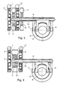
- Figur 4 eine Ausgestaltung der Ausführung der erfindungsgemäßen Kupplungsbetätigungsvorrichtung für ein Parallelschaltgetriebe nach Figur 3.
- In der Figur 1 ist der prinzipielle Aufbau einer erfindungsgemäßen Kupplungsbetätigungsvorrichtung dargestellt, wobei ein Schneckenrad 1 eines Schneckengetriebes durch einen Elektromotor (nicht dargestellt) angetrieben wird. Das Schneckenrad 1 treibt das Zwischenrad 3 eines Planetengetriebes an. Das Planetengetriebe umfasst weiterhin ein Hohlrad 2. Ein Drehhebel 6 wird durch das Planetengetriebe angetrieben und verdreht und betätigt mit einer Gabel 5 ein Ausrücklager (nicht dargestellt) einer zugeordneten Kupplung (nicht dargestellt).
- Eine Kompensationsfeder 4 wird beispielsweise als Spiralfeder zwischen einem Planetenträger und einer Hohlradfixierung (oder im unteren Lager) integriert. Beispielsweise werden folgende Übersetzungen nach der Figur 1 eingesetzt: Schneckenrad 1 mit 2,8 mm pro Umdrehung; Hohlrad 2 mit 56 Zähnen; Zwischenrad 3 mit 68 Zähnen außen und 16 Zähnen gegenüber einem Sonnenrad. Die Übersetzung des Planetensatzes beträgt damit 4,4. Durch die Kombination aus Schneckengetriebe und Planetengetriebe ergibt sich pro Umdrehung des Elektromotors eine Gesamtübersetzung (Ausrückweg) an der Gabel von 0,9 mm bis 1,2 mm.
- In der Figur 2 ist eine Axialverzahnung 7 dargestellt, die zwischen Getriebe und Drehhebel 6 vorgesehen ist, um eine lösbare Aktoreinheit zu schaffen. Die Axialverzahnung 7 ist spielfrei ausgebildet und vorzugsweise am oberen Wellenende des Drehhebels 6 angeordnet.
- Bei einer Doppelkupplung, wie in der Figur 3 nach einer weiteren Ausführungsform der vorliegenden Erfindung gezeigt, werden zwei Drehhebel 6 und 10 eingebaut, die voneinander unabhängig arbeiten können. Hierzu ist eine geschickte Verschachtelung und Anordnung der Bauteile in einer Kupplungsglocke notwendig, um ausreichend Betätigungsweg zu gewährleisten. Aus unterschiedlichen Komponenten und Lagerungen lassen sich verschiedene Drehhebelvarianten aufbauen.
- Ein erstes Schneckenrad 1 wird durch einen Elektromotor (nicht dargestellt) angetrieben und treibt wiederum das Zwischenrad 3 eines ersten Planetengetriebes an. Ein Hohlrad 2 und eine Kompensationsfeder 4 sind wie bei der ersten Ausführungsform nach der Figur 1 ebenfalls vorhanden. Dieses erste Planetengetriebe treibt den ersten Drehhebel 6 an, der wiederum über die erste Gabel 5 auf ein erstes Ausrücklager 8 einer ersten Kupplung einwirkt. Ein zweites Schneckenrad 13 wird durch einen Elektromotor (nicht dargestellt) angetrieben und treibt wiederum das zweite Zwischenrad eines zweiten Planetengetriebes an. Ein zweites Hohlrad 14 und eine Kompensationsfeder 12 sind ebenfalls vorgesehen. Dieses zweite Planetengetriebe treibt den zweiten Drehhebel 10 an, der wiederum über die zweite Gabel 11 auf ein zweites Ausrücklager 9 einer zweiten Kupplung einwirkt.
- In der Figur 4 ist eine weitere Ausführungsform der Erfindung dargestellt, bei der ein gemeinsames Hohlrad 2 für beide Planetengetriebe Verwendung findet. Ansonsten entspricht der Aufbau der Kupplungsbetätigungsvorrichtung nach der Figur 3.
- Prinzipiell lässt sich das Schneckengetriebe dem Planetengetriebe vor- oder nachschalten. In den gezeigten Ausführungsformen ist das Schneckengetriebe dem Planetengetriebe vorgeschaltet.
-
- 1
- Schneckenrad
- 2
- Hohlrad
- 3
- Zwischenrad
- 4
- Kompensationsfeder
- 5
- Gabel, erste
- 6
- Drehhebel, erster
- 7
- Axialverzahnung
- 8
- Ausrücklager, erstes
- 9
- Ausrücklager, zweites
- 10
- Drehhebel, zweiter
- 11
- Gabel, zweite
- 12
- Kompensationsfeder
- 13
- Schneckenrad
- 14
- Hohlrad
Claims (10)
- Kupplungsbetätigungsvorrichtung, insbesondere für eine Kupplung eines Kraftfahrzeuges, mit einem Drehhebel (6, 10) als Teil einer elektromechanischen Kraftübertragungsstrecke, der mittels einer Gabel (5, 11) ein Ausrücklager (8, 9) der Kupplung betätigt, wobei der Drehhebel (6, 10) über ein Planetengetriebe von einem Antrieb angetrieben ist, dadurch gekennzeichnet, dass dem Planetengetriebe ein Schneckengetriebe vor- oder nachgeschaltet ist.
- Kupplungsbetätigungsvorrichtung nach Anspruch 1, dadurch gekennzeichnet, dass ein Doppelkupplungsgetriebe betätigt wird, wobei ein erster Drehhebel (6) mittels einer ersten Gabel (5) auf ein erstes Ausrücklager (8) einer ersten Kupplung einwirkt und ein zweiter Drehhebel (10) mittels einer zweiten Gabel (11) auf ein zweites Ausrücklager (9) einer zweiten Kupplung einwirkt, und jeder Drehhebel (6, 10) durch ein Planetengetriebe angetrieben, dem ein Schneckengetriebe vorgeschaltet.
- Kupplungsbetätigungsvorrichtung nach Anspruch 1 oder 2, dadurch gekennzeichnet, dass der Antrieb jedes Schneckengetriebes mittels eines Elektromotors erfolgt.
- Kupplungsbetätigungsvorrichtung nach Anspruch 3, dadurch gekennzeichnet, dass die Gesamtübersetzung von Planetengetriebe und Schneckengetriebe pro Umdrehung des Elektromotors im Bereich von 0,9 bis 1,2 mm Ausrückweg der Gabel (5, 11) liegt.
- Kupplungsbetätigungsvorrichtung nach Anspruch 1 oder 2, dadurch gekennzeichnet, dass zwischen einem Planetenträger und einer Hohlradfixierung des Planetengetriebes eine Kompensationsfeder (4, 12) angeordnet ist.
- Kupplungsbetätigungsvorrichtung nach Anspruch 5, dadurch gekennzeichnet, dass die Kompensationsfeder (4, 12) eine Spiralfeder ist.
- Kupplungsbetätigungsvorrichtung nach Anspruch 1, dadurch gekennzeichnet, dass zwischen einem Ausgang des Planetengetriebes und dem Drehhebel (6, 10) eine Axialverzahnung (7) vorgesehen ist.
- Kupplungsbetätigungsvorrichtung für ein Doppelkupplungsgetriebe nach Anspruch 2, dadurch gekennzeichnet, dass für die Betätigung des Doppelkupplungsgetriebes die Planetengetriebe, die Schneckengetriebe und die Drehhebel (6, 10) ineinander verschachtelt montiert sind.
- Kupplungsbetätigungsvorrichtung nach Anspruch 2, dadurch gekennzeichnet, dass ein Hohlrad (2) für beide Planetengetriebe gemeinsam vorgesehen ist.
- Kupplungsbetätigungsvorrichtung für ein Doppelkupplungsgetriebe nach Anspruch 2, dadurch gekennzeichnet, dass die Drehachsen der beiden Drehhebel (6, 10) koaxial angeordnet sind.
Applications Claiming Priority (1)
| Application Number | Priority Date | Filing Date | Title |
|---|---|---|---|
| DE102005055222 | 2005-11-19 |
Publications (3)
| Publication Number | Publication Date |
|---|---|
| EP1806514A2 true EP1806514A2 (de) | 2007-07-11 |
| EP1806514A3 EP1806514A3 (de) | 2007-07-18 |
| EP1806514B1 EP1806514B1 (de) | 2013-06-12 |
Family
ID=38055437
Family Applications (1)
| Application Number | Title | Priority Date | Filing Date |
|---|---|---|---|
| EP06022116.5A Not-in-force EP1806514B1 (de) | 2005-11-19 | 2006-10-21 | Kupplungsbetätigungsvorrichtung |
Country Status (1)
| Country | Link |
|---|---|
| EP (1) | EP1806514B1 (de) |
Cited By (1)
| Publication number | Priority date | Publication date | Assignee | Title |
|---|---|---|---|---|
| DE102020113204A1 (de) | 2020-05-15 | 2021-11-18 | Schaeffler Technologies AG & Co. KG | CVT-Getriebe |
Family Cites Families (4)
| Publication number | Priority date | Publication date | Assignee | Title |
|---|---|---|---|---|
| US2967596A (en) * | 1959-01-05 | 1961-01-10 | Caterpillar Tractor Co | Locking mechanism for power transmission |
| FR2558551B1 (fr) * | 1984-01-25 | 1989-05-19 | Valeo | Commande d'embrayage dont les conditions de montage sont ameliorees |
| IT1270209B (it) * | 1994-06-10 | 1997-04-29 | Bottega Del Giardinaggio S A S | Dispositivo per innesto a molla elicoidale tra due alberi mediante cursore cilindrico assiale |
| JP4038104B2 (ja) * | 2002-09-26 | 2008-01-23 | アイシン精機株式会社 | クラッチ用アクチュエータ |
-
2006
- 2006-10-21 EP EP06022116.5A patent/EP1806514B1/de not_active Not-in-force
Cited By (1)
| Publication number | Priority date | Publication date | Assignee | Title |
|---|---|---|---|---|
| DE102020113204A1 (de) | 2020-05-15 | 2021-11-18 | Schaeffler Technologies AG & Co. KG | CVT-Getriebe |
Also Published As
| Publication number | Publication date |
|---|---|
| EP1806514A3 (de) | 2007-07-18 |
| EP1806514B1 (de) | 2013-06-12 |
Similar Documents
| Publication | Publication Date | Title |
|---|---|---|
| DE102012007061B4 (de) | Parksperrenanordnung und Kraftfahrzeuggetriebe | |
| EP2304276B1 (de) | Schaltanordnung | |
| EP2250397B1 (de) | Betätigungsanordnung eines zentralsynchronisierten doppelkupplungsgetriebes | |
| EP2250408B1 (de) | Anordnung zum schalten von zumindest zwei losrädern | |
| EP1936234A2 (de) | Doppelkupplungsgetriebe | |
| EP3821155A2 (de) | Lastschaltbares mehrganggetriebe | |
| DE102012206936A1 (de) | Hybridgetriebe | |
| EP2918877B1 (de) | Schaltanordnung für ein Kraftfahrzeuggetriebe und Schaltverfahren | |
| DE102019130357B4 (de) | Aktuatoranordnung und Getriebeanordnung mit einer solchen Aktuatoranordnung | |
| EP2143980A2 (de) | Anordnung zum Wählen und Schalten von Gängen bei einem Schaltgetriebe eines Fahrzeuges | |
| EP1279869A2 (de) | Stellvorrichtung für ein automatisiertes Stufengetriebe eines Kraftfahrzeuges | |
| DE102005000700A1 (de) | Vorrichtung zur Betätigung von Schaltgabeln | |
| EP3368799B1 (de) | Schaltvorrichtung und antriebseinheit für ein kraftfahrzeug | |
| DE102011082828A1 (de) | Schalteinheit mit Spindeltrieb für ein Werkzeugmaschinengetriebe | |
| DE102008000643B4 (de) | Anordnung zum Schalten von zumindest einem Losrad an einer zugeordneten Welle eines Getriebes | |
| EP1806514B1 (de) | Kupplungsbetätigungsvorrichtung | |
| DE102008000635A1 (de) | Anordnung zur Betätigung zumindest einer Schalteinrichtung eines Getriebes | |
| DE102019119952B4 (de) | Antriebsvorrichtung für ein Kraftfahrzeug mit wahlweise gehäusefest schaltbarem Planetenradträger oder Hohlrad | |
| DE102019202598B4 (de) | Doppelkupplungsgetriebe | |
| DE102005039559B4 (de) | Elektromechanische Getriebesteuerung | |
| DE102019131781A1 (de) | Antriebssystem mit im Planetenradsatz implementierter Synchroeinheit als Parksperre | |
| EP3976995A1 (de) | Automatisiertes schaltgetriebe | |
| DE102006049732A1 (de) | Kupplungsbetätigungsvorrichtung | |
| DE102014207080B4 (de) | Reibungskupplung | |
| EP3056774B1 (de) | Schaltanordnung für ein Kraftfahrzeuggetriebe und Schaltverfahren |
Legal Events
| Date | Code | Title | Description |
|---|---|---|---|
| PUAI | Public reference made under article 153(3) epc to a published international application that has entered the european phase |
Free format text: ORIGINAL CODE: 0009012 |
|
| PUAL | Search report despatched |
Free format text: ORIGINAL CODE: 0009013 |
|
| AK | Designated contracting states |
Kind code of ref document: A2 Designated state(s): AT BE BG CH CY CZ DE DK EE ES FI FR GB GR HU IE IS IT LI LT LU LV MC NL PL PT RO SE SI SK TR |
|
| AX | Request for extension of the european patent |
Extension state: AL BA HR MK YU |
|
| AK | Designated contracting states |
Kind code of ref document: A3 Designated state(s): AT BE BG CH CY CZ DE DK EE ES FI FR GB GR HU IE IS IT LI LT LU LV MC NL PL PT RO SE SI SK TR |
|
| AX | Request for extension of the european patent |
Extension state: AL BA HR MK YU |
|
| 17P | Request for examination filed |
Effective date: 20080118 |
|
| 17Q | First examination report despatched |
Effective date: 20080214 |
|
| AKX | Designation fees paid |
Designated state(s): AT BE BG CH CY CZ DE DK EE ES FI FR GB GR HU IE IS IT LI LT LU LV MC NL PL PT RO SE SI SK TR |
|
| RAP1 | Party data changed (applicant data changed or rights of an application transferred) |
Owner name: SCHAEFFLER TECHNOLOGIES GMBH & CO. KG |
|
| RAP1 | Party data changed (applicant data changed or rights of an application transferred) |
Owner name: SCHAEFFLER TECHNOLOGIES AG & CO. KG |
|
| GRAP | Despatch of communication of intention to grant a patent |
Free format text: ORIGINAL CODE: EPIDOSNIGR1 |
|
| GRAS | Grant fee paid |
Free format text: ORIGINAL CODE: EPIDOSNIGR3 |
|
| GRAA | (expected) grant |
Free format text: ORIGINAL CODE: 0009210 |
|
| AK | Designated contracting states |
Kind code of ref document: B1 Designated state(s): AT BE BG CH CY CZ DE DK EE ES FI FR GB GR HU IE IS IT LI LT LU LV MC NL PL PT RO SE SI SK TR |
|
| REG | Reference to a national code |
Ref country code: GB Ref legal event code: FG4D Free format text: NOT ENGLISH |
|
| REG | Reference to a national code |
Ref country code: CH Ref legal event code: EP |
|
| REG | Reference to a national code |
Ref country code: AT Ref legal event code: REF Ref document number: 616795 Country of ref document: AT Kind code of ref document: T Effective date: 20130615 |
|
| REG | Reference to a national code |
Ref country code: IE Ref legal event code: FG4D Free format text: LANGUAGE OF EP DOCUMENT: GERMAN |
|
| REG | Reference to a national code |
Ref country code: DE Ref legal event code: R096 Ref document number: 502006012929 Country of ref document: DE Effective date: 20130801 |
|
| PG25 | Lapsed in a contracting state [announced via postgrant information from national office to epo] |
Ref country code: SE Free format text: LAPSE BECAUSE OF FAILURE TO SUBMIT A TRANSLATION OF THE DESCRIPTION OR TO PAY THE FEE WITHIN THE PRESCRIBED TIME-LIMIT Effective date: 20130612 Ref country code: ES Free format text: LAPSE BECAUSE OF FAILURE TO SUBMIT A TRANSLATION OF THE DESCRIPTION OR TO PAY THE FEE WITHIN THE PRESCRIBED TIME-LIMIT Effective date: 20130923 Ref country code: LT Free format text: LAPSE BECAUSE OF FAILURE TO SUBMIT A TRANSLATION OF THE DESCRIPTION OR TO PAY THE FEE WITHIN THE PRESCRIBED TIME-LIMIT Effective date: 20130612 Ref country code: FI Free format text: LAPSE BECAUSE OF FAILURE TO SUBMIT A TRANSLATION OF THE DESCRIPTION OR TO PAY THE FEE WITHIN THE PRESCRIBED TIME-LIMIT Effective date: 20130612 Ref country code: SI Free format text: LAPSE BECAUSE OF FAILURE TO SUBMIT A TRANSLATION OF THE DESCRIPTION OR TO PAY THE FEE WITHIN THE PRESCRIBED TIME-LIMIT Effective date: 20130612 Ref country code: GR Free format text: LAPSE BECAUSE OF FAILURE TO SUBMIT A TRANSLATION OF THE DESCRIPTION OR TO PAY THE FEE WITHIN THE PRESCRIBED TIME-LIMIT Effective date: 20130913 |
|
| REG | Reference to a national code |
Ref country code: NL Ref legal event code: VDEP Effective date: 20130612 |
|
| REG | Reference to a national code |
Ref country code: LT Ref legal event code: MG4D |
|
| PG25 | Lapsed in a contracting state [announced via postgrant information from national office to epo] |
Ref country code: BG Free format text: LAPSE BECAUSE OF FAILURE TO SUBMIT A TRANSLATION OF THE DESCRIPTION OR TO PAY THE FEE WITHIN THE PRESCRIBED TIME-LIMIT Effective date: 20130912 |
|
| PG25 | Lapsed in a contracting state [announced via postgrant information from national office to epo] |
Ref country code: LV Free format text: LAPSE BECAUSE OF FAILURE TO SUBMIT A TRANSLATION OF THE DESCRIPTION OR TO PAY THE FEE WITHIN THE PRESCRIBED TIME-LIMIT Effective date: 20130612 |
|
| PG25 | Lapsed in a contracting state [announced via postgrant information from national office to epo] |
Ref country code: EE Free format text: LAPSE BECAUSE OF FAILURE TO SUBMIT A TRANSLATION OF THE DESCRIPTION OR TO PAY THE FEE WITHIN THE PRESCRIBED TIME-LIMIT Effective date: 20130612 Ref country code: PT Free format text: LAPSE BECAUSE OF FAILURE TO SUBMIT A TRANSLATION OF THE DESCRIPTION OR TO PAY THE FEE WITHIN THE PRESCRIBED TIME-LIMIT Effective date: 20131014 Ref country code: SK Free format text: LAPSE BECAUSE OF FAILURE TO SUBMIT A TRANSLATION OF THE DESCRIPTION OR TO PAY THE FEE WITHIN THE PRESCRIBED TIME-LIMIT Effective date: 20130612 Ref country code: IS Free format text: LAPSE BECAUSE OF FAILURE TO SUBMIT A TRANSLATION OF THE DESCRIPTION OR TO PAY THE FEE WITHIN THE PRESCRIBED TIME-LIMIT Effective date: 20131012 Ref country code: CZ Free format text: LAPSE BECAUSE OF FAILURE TO SUBMIT A TRANSLATION OF THE DESCRIPTION OR TO PAY THE FEE WITHIN THE PRESCRIBED TIME-LIMIT Effective date: 20130612 |
|
| PG25 | Lapsed in a contracting state [announced via postgrant information from national office to epo] |
Ref country code: PL Free format text: LAPSE BECAUSE OF FAILURE TO SUBMIT A TRANSLATION OF THE DESCRIPTION OR TO PAY THE FEE WITHIN THE PRESCRIBED TIME-LIMIT Effective date: 20130612 Ref country code: NL Free format text: LAPSE BECAUSE OF FAILURE TO SUBMIT A TRANSLATION OF THE DESCRIPTION OR TO PAY THE FEE WITHIN THE PRESCRIBED TIME-LIMIT Effective date: 20130612 Ref country code: RO Free format text: LAPSE BECAUSE OF FAILURE TO SUBMIT A TRANSLATION OF THE DESCRIPTION OR TO PAY THE FEE WITHIN THE PRESCRIBED TIME-LIMIT Effective date: 20130612 |
|
| RAP2 | Party data changed (patent owner data changed or rights of a patent transferred) |
Owner name: SCHAEFFLER TECHNOLOGIES GMBH & CO. KG |
|
| REG | Reference to a national code |
Ref country code: DE Ref legal event code: R081 Ref document number: 502006012929 Country of ref document: DE Owner name: SCHAEFFLER TECHNOLOGIES AG & CO. KG, DE Free format text: FORMER OWNER: SCHAEFFLER TECHNOLOGIES AG & CO. KG, 91074 HERZOGENAURACH, DE Effective date: 20140214 Ref country code: DE Ref legal event code: R081 Ref document number: 502006012929 Country of ref document: DE Owner name: SCHAEFFLER TECHNOLOGIES AG & CO. KG, DE Free format text: FORMER OWNER: LUK LAMELLEN UND KUPPLUNGSBAU BETEILIGUNGS KG, 77815 BUEHL, DE Effective date: 20130612 Ref country code: DE Ref legal event code: R081 Ref document number: 502006012929 Country of ref document: DE Owner name: SCHAEFFLER TECHNOLOGIES GMBH & CO. KG, DE Free format text: FORMER OWNER: SCHAEFFLER TECHNOLOGIES AG & CO. KG, 91074 HERZOGENAURACH, DE Effective date: 20140214 Ref country code: DE Ref legal event code: R081 Ref document number: 502006012929 Country of ref document: DE Owner name: SCHAEFFLER TECHNOLOGIES GMBH & CO. KG, DE Free format text: FORMER OWNER: LUK LAMELLEN UND KUPPLUNGSBAU BETEILIGUNGS KG, 77815 BUEHL, DE Effective date: 20130612 |
|
| PLBE | No opposition filed within time limit |
Free format text: ORIGINAL CODE: 0009261 |
|
| STAA | Information on the status of an ep patent application or granted ep patent |
Free format text: STATUS: NO OPPOSITION FILED WITHIN TIME LIMIT |
|
| BERE | Be: lapsed |
Owner name: SCHAEFFLER TECHNOLOGIES A.G. & CO. KG Effective date: 20131031 |
|
| PG25 | Lapsed in a contracting state [announced via postgrant information from national office to epo] |
Ref country code: DK Free format text: LAPSE BECAUSE OF FAILURE TO SUBMIT A TRANSLATION OF THE DESCRIPTION OR TO PAY THE FEE WITHIN THE PRESCRIBED TIME-LIMIT Effective date: 20130612 |
|
| 26N | No opposition filed |
Effective date: 20140313 |
|
| PG25 | Lapsed in a contracting state [announced via postgrant information from national office to epo] |
Ref country code: MC Free format text: LAPSE BECAUSE OF FAILURE TO SUBMIT A TRANSLATION OF THE DESCRIPTION OR TO PAY THE FEE WITHIN THE PRESCRIBED TIME-LIMIT Effective date: 20130612 |
|
| REG | Reference to a national code |
Ref country code: CH Ref legal event code: PL |
|
| GBPC | Gb: european patent ceased through non-payment of renewal fee |
Effective date: 20131021 |
|
| REG | Reference to a national code |
Ref country code: DE Ref legal event code: R097 Ref document number: 502006012929 Country of ref document: DE Effective date: 20140313 |
|
| REG | Reference to a national code |
Ref country code: IE Ref legal event code: MM4A |
|
| PG25 | Lapsed in a contracting state [announced via postgrant information from national office to epo] |
Ref country code: CH Free format text: LAPSE BECAUSE OF NON-PAYMENT OF DUE FEES Effective date: 20131031 Ref country code: LI Free format text: LAPSE BECAUSE OF NON-PAYMENT OF DUE FEES Effective date: 20131031 Ref country code: GB Free format text: LAPSE BECAUSE OF NON-PAYMENT OF DUE FEES Effective date: 20131021 |
|
| PG25 | Lapsed in a contracting state [announced via postgrant information from national office to epo] |
Ref country code: BE Free format text: LAPSE BECAUSE OF NON-PAYMENT OF DUE FEES Effective date: 20131031 |
|
| PG25 | Lapsed in a contracting state [announced via postgrant information from national office to epo] |
Ref country code: IE Free format text: LAPSE BECAUSE OF NON-PAYMENT OF DUE FEES Effective date: 20131021 |
|
| REG | Reference to a national code |
Ref country code: AT Ref legal event code: MM01 Ref document number: 616795 Country of ref document: AT Kind code of ref document: T Effective date: 20131021 |
|
| PG25 | Lapsed in a contracting state [announced via postgrant information from national office to epo] |
Ref country code: AT Free format text: LAPSE BECAUSE OF NON-PAYMENT OF DUE FEES Effective date: 20131021 |
|
| REG | Reference to a national code |
Ref country code: DE Ref legal event code: R081 Ref document number: 502006012929 Country of ref document: DE Owner name: SCHAEFFLER TECHNOLOGIES AG & CO. KG, DE Free format text: FORMER OWNER: SCHAEFFLER TECHNOLOGIES GMBH & CO. KG, 91074 HERZOGENAURACH, DE Effective date: 20150213 |
|
| PGFP | Annual fee paid to national office [announced via postgrant information from national office to epo] |
Ref country code: IT Payment date: 20141022 Year of fee payment: 9 |
|
| PG25 | Lapsed in a contracting state [announced via postgrant information from national office to epo] |
Ref country code: CY Free format text: LAPSE BECAUSE OF FAILURE TO SUBMIT A TRANSLATION OF THE DESCRIPTION OR TO PAY THE FEE WITHIN THE PRESCRIBED TIME-LIMIT Effective date: 20130612 Ref country code: TR Free format text: LAPSE BECAUSE OF FAILURE TO SUBMIT A TRANSLATION OF THE DESCRIPTION OR TO PAY THE FEE WITHIN THE PRESCRIBED TIME-LIMIT Effective date: 20130612 |
|
| PG25 | Lapsed in a contracting state [announced via postgrant information from national office to epo] |
Ref country code: LU Free format text: LAPSE BECAUSE OF NON-PAYMENT OF DUE FEES Effective date: 20131021 Ref country code: HU Free format text: LAPSE BECAUSE OF FAILURE TO SUBMIT A TRANSLATION OF THE DESCRIPTION OR TO PAY THE FEE WITHIN THE PRESCRIBED TIME-LIMIT; INVALID AB INITIO Effective date: 20061021 |
|
| REG | Reference to a national code |
Ref country code: FR Ref legal event code: PLFP Year of fee payment: 10 |
|
| PG25 | Lapsed in a contracting state [announced via postgrant information from national office to epo] |
Ref country code: IT Free format text: LAPSE BECAUSE OF NON-PAYMENT OF DUE FEES Effective date: 20151021 |
|
| REG | Reference to a national code |
Ref country code: FR Ref legal event code: PLFP Year of fee payment: 11 |
|
| REG | Reference to a national code |
Ref country code: FR Ref legal event code: PLFP Year of fee payment: 12 |
|
| PGFP | Annual fee paid to national office [announced via postgrant information from national office to epo] |
Ref country code: FR Payment date: 20171031 Year of fee payment: 12 |
|
| PGFP | Annual fee paid to national office [announced via postgrant information from national office to epo] |
Ref country code: DE Payment date: 20171229 Year of fee payment: 12 |
|
| REG | Reference to a national code |
Ref country code: DE Ref legal event code: R119 Ref document number: 502006012929 Country of ref document: DE |
|
| PG25 | Lapsed in a contracting state [announced via postgrant information from national office to epo] |
Ref country code: DE Free format text: LAPSE BECAUSE OF NON-PAYMENT OF DUE FEES Effective date: 20190501 |
|
| PG25 | Lapsed in a contracting state [announced via postgrant information from national office to epo] |
Ref country code: FR Free format text: LAPSE BECAUSE OF NON-PAYMENT OF DUE FEES Effective date: 20181031 |
|
| P01 | Opt-out of the competence of the unified patent court (upc) registered |
Effective date: 20230522 |