EP1806017B1 - Reduction of power consumption in wireless communication terminals - Google Patents
Reduction of power consumption in wireless communication terminals Download PDFInfo
- Publication number
- EP1806017B1 EP1806017B1 EP04791417A EP04791417A EP1806017B1 EP 1806017 B1 EP1806017 B1 EP 1806017B1 EP 04791417 A EP04791417 A EP 04791417A EP 04791417 A EP04791417 A EP 04791417A EP 1806017 B1 EP1806017 B1 EP 1806017B1
- Authority
- EP
- European Patent Office
- Prior art keywords
- wireless communication
- communication device
- receiver
- communication terminal
- signal
- Prior art date
- Legal status (The legal status is an assumption and is not a legal conclusion. Google has not performed a legal analysis and makes no representation as to the accuracy of the status listed.)
- Active
Links
Images


Classifications
-
- G—PHYSICS
- G06—COMPUTING; CALCULATING OR COUNTING
- G06F—ELECTRIC DIGITAL DATA PROCESSING
- G06F1/00—Details not covered by groups G06F3/00 - G06F13/00 and G06F21/00
- G06F1/26—Power supply means, e.g. regulation thereof
- G06F1/32—Means for saving power
- G06F1/3203—Power management, i.e. event-based initiation of a power-saving mode
- G06F1/3206—Monitoring of events, devices or parameters that trigger a change in power modality
- G06F1/3215—Monitoring of peripheral devices
-
- G—PHYSICS
- G06—COMPUTING; CALCULATING OR COUNTING
- G06F—ELECTRIC DIGITAL DATA PROCESSING
- G06F1/00—Details not covered by groups G06F3/00 - G06F13/00 and G06F21/00
- G06F1/26—Power supply means, e.g. regulation thereof
- G06F1/32—Means for saving power
- G06F1/3203—Power management, i.e. event-based initiation of a power-saving mode
- G06F1/3234—Power saving characterised by the action undertaken
- G06F1/325—Power saving in peripheral device
-
- H—ELECTRICITY
- H04—ELECTRIC COMMUNICATION TECHNIQUE
- H04W—WIRELESS COMMUNICATION NETWORKS
- H04W52/00—Power management, e.g. TPC [Transmission Power Control], power saving or power classes
- H04W52/02—Power saving arrangements
- H04W52/0209—Power saving arrangements in terminal devices
- H04W52/0225—Power saving arrangements in terminal devices using monitoring of external events, e.g. the presence of a signal
- H04W52/0245—Power saving arrangements in terminal devices using monitoring of external events, e.g. the presence of a signal according to signal strength
-
- H—ELECTRICITY
- H04—ELECTRIC COMMUNICATION TECHNIQUE
- H04W—WIRELESS COMMUNICATION NETWORKS
- H04W52/00—Power management, e.g. TPC [Transmission Power Control], power saving or power classes
- H04W52/02—Power saving arrangements
- H04W52/0209—Power saving arrangements in terminal devices
- H04W52/0212—Power saving arrangements in terminal devices managed by the network, e.g. network or access point is master and terminal is slave
- H04W52/0219—Power saving arrangements in terminal devices managed by the network, e.g. network or access point is master and terminal is slave where the power saving management affects multiple terminals
-
- Y—GENERAL TAGGING OF NEW TECHNOLOGICAL DEVELOPMENTS; GENERAL TAGGING OF CROSS-SECTIONAL TECHNOLOGIES SPANNING OVER SEVERAL SECTIONS OF THE IPC; TECHNICAL SUBJECTS COVERED BY FORMER USPC CROSS-REFERENCE ART COLLECTIONS [XRACs] AND DIGESTS
- Y02—TECHNOLOGIES OR APPLICATIONS FOR MITIGATION OR ADAPTATION AGAINST CLIMATE CHANGE
- Y02D—CLIMATE CHANGE MITIGATION TECHNOLOGIES IN INFORMATION AND COMMUNICATION TECHNOLOGIES [ICT], I.E. INFORMATION AND COMMUNICATION TECHNOLOGIES AIMING AT THE REDUCTION OF THEIR OWN ENERGY USE
- Y02D30/00—Reducing energy consumption in communication networks
- Y02D30/70—Reducing energy consumption in communication networks in wireless communication networks
Definitions
- the invention relates generally to the reduction of power consumption in wireless communication terminals. More particularly, the present invention concerns a mechanism for decreasing power consumption through control of receiver performance in wireless terminals.
- wireless Internet access is typically based on either short-range wireless systems or mobile networks, or both.
- Short-range wireless systems have a typical range of one hundred meters or less. They often combine with systems wired to the internet to provide communication over long distances.
- the category of short-range wireless systems includes wireless personal area networks (PANs) and wireless local area networks (WLANs). They have the common feature of operating in unlicensed portions of the radio spectrum, usually either in the 2.4 GHz Industrial, Scientific, and Medical (ISM) band or in the 5 GHz unlicensed band.
- PANs personal area networks
- WLANs wireless local area networks
- Wireless personal area networks use low cost, low power wireless devices that have a typical range of about ten meters.
- the best-known example of wireless personal area network technology is Bluetooth, which uses the 2.4 GHz ISM band. It provides a peak air link speed of one Mbps, and power consumption low enough for use in personal, portable electronics such as PDAs and mobile phones.
- Wireless local area networks generally operate at higher peak speeds of 10 to 100 Mbps and have a longer range, which requires greater power consumption.
- Wireless LAN systems are typically extensions of a wired network, providing mobile users with wireless access to the wired network.
- wireless local area network technology examples include the IEEE 802.11 a, which is designed for the 5 GHz unlicensed band, and uses orthogonal frequency division multiplexing (OFDM) to deliver up to 54 Mbps data rates; the 802.11 b, which is designed for the 2.4 GHz ISM band and uses direct sequence spread spectrum (DSSS) to deliver up to 11 Mbps data rates; and the HIPERLAN Standard, which is designed to operate in the 5 GHz unlicensed band.
- OFDM orthogonal frequency division multiplexing
- DSSS direct sequence spread spectrum
- An ad-hoc network is formed by two or more independent mobile terminals without the services of a base station, i.e. in an ad-hoc network the terminals communicate on a peer-to-peer basis.
- An ad-hoc network is normally formed for temporary purposes.
- the infrastructure network comprises one or more wireless base stations, called access points, which form part of the wired infrastructure. In a typical network of this type, all traffic goes through the access points, regardless of whether the traffic is between two terminals or a terminal and the wired network, i.e. the mobile terminals do not communicate on a peer-to-peer basis.
- the mobile terminals are provided with wireless LAN cards, whereby they can access the wired network or set up an ad-hoc network.
- an access point and at least one terminal is said to form a Basic Serving Set (BSS), while an ad-hoc network is also termed an Independent BSS (IBSS).
- BSS Basic Serving Set
- IBSS Independent BSS
- wireless LAN technology has been used mainly in laptop computers, which are typically AC powered, but which may also be used in battery mode that provides a fairly high battery capacity.
- the WLAN standards define a specific power save mode into which the terminals may enter from an active mode in order to decrease their power consumption. In this mode the WLAN-specific power consumption is very low, but the terminals have to wake up (i.e. enter the active mode) periodically to receive regular beacon transmissions broadcast in the network.
- the beacon transmissions indicate, for example, whether there are incoming packets buffered for a terminal. If so, the terminal retrieves the packets, goes back to sleep, and wakes up again to listen to the next beacon transmission.
- the current WLAN power management has been designed assuming that the terminal devices are laptop type computers featuring a relatively high battery capacity.
- the terminal devices are laptop type computers featuring a relatively high battery capacity.
- power consumption has, however, become a critical issue when new properties are designed for wireless systems and terminals. Emerging ad-hoc mode applications in which power consumption may be rather high further aggravate the problem. Examples of such applications are games played in small groups or business meetings in which large files may be shared (wirelessly) by the participants.
- Power consumption of the WLAN terminals has normally been reduced by trying to maximize the time the terminals spend in the power save mode. However, this does not affect the power consumption in the active mode, whose proportion of overall time, i.e. percentage of time in active mode, is on the increase along the generalization of new functionalities.
- Document US 6,542,517 B1 generally deals with power savings in mobile terminals by operating a mobile terminal in two separate modes including a first mode suitable for receiving telephone calls and a second mode suitable for receiving pages only.
- the present invention seeks to accomplish a solution by means of which the power consumption of a terminal may be reduced in the active mode of the terminal in a WLAN-like communication system provided with an uncoordinated media access mechanism, i.e. in a system where the terminals have to sense the common air medium prior to transmission to see whether the medium is free.
- the present invention seeks to devise a new mechanism for decreasing power consumption in wireless terminals operating in wireless communication systems where a common channel is to be listened to prior to transmission to determine if the channel is free.
- a terminal selects the device(s) with which it will communicate and controls the performance of its receiver in two different control modes, namely in a reception control mode intended for listening to the selected device(s) and in a media access control mode intended for sensing the common air medium prior to its own transmission.
- the performance control is carried out in a manner allowing performance degradation to translate into reduced power consumption.
- Preferred methods for controlling the performance of the receiver include control of the dynamic range and/or the sensitivity of the receiver.
- the dynamic range here refers to the input power range over which the receiver produces a useful output.
- Sensitivity in turn refers generally to the ability of the receiver to detect (weak) signals, i.e. degraded sensitivity diminishes the area from which devices may be detected.
- the concept of dynamic range contains the concept of sensitivity, since the low end of the dynamic range is governed by sensitivity. The performance of the receiver may be degraded especially in the reception control mode, and the degradation can in turn be implemented so that power consumption is reduced in the transceiver.
- the terminal selects the device(s) with which it communicates each time.
- the selected device(s) typically form a subset of all possible communicating peers in the same network.
- the terminal further measures a signal quality variable from at least one of the selected device(s), each signal quality variable being indicative of the quality of the signal received from respective device.
- the quality variable is typically indicative of the strength of the received signal. If no transmission to the selected device(s) is required, the performance of the receiver of the terminal may be adjusted based on the signal quality variable(s) obtained based on the said device(s) only. Thus, if transmission is not required, the terminal may restrict the operation range of its receiver according to the signal(s) received from the said device(s).
- the terminal may receive with degraded performance, i.e. with reduced power consumption, but it may also make the devices outside this area so-called hidden nodes, i.e. nodes that cannot be detected.
- hidden nodes i.e. nodes that cannot be detected.
- the terminal readjusts the performance of its receiver so that it may detect, when sensing the common medium, all such devices whose traffic the upcoming transmission may disturb. In this way the terminal may ascertain that the hidden node problem is not aggravated.
- one embodiment of the invention is the provision of a method for decreasing power consumption in a wireless communication terminal.
- the method includes the steps of selecting at least one communication device as a communicating peer in a wireless communication system and measuring a signal quality variable from at least one of the at least one communication device selected in the selecting step, each signal quality variable being measured based on a signal received from a respective one of the at least one communication device selected in the selecting step, whereby at least one signal quality variable is obtained.
- the method further includes the steps of adjusting receiver performance based on at least one of the at least one signal quality variable obtained in the measuring step, the adjusting step being performed for reducing power consumption while ensuring reception of respective signals from the at least one communication device selected in the selecting step, monitoring if the wireless communication terminal's own transmission is approaching, and readjusting receiver performance for determining the availability of the common air medium at a performance level enabling detection of transmitting communication devices within a coverage area of said own transmission, the readjusting step being performed when the monitoring step indicates that said own transmission is approaching.
- the invention provides a wireless terminal for a wireless communication system where terminals are required to determine the availability of the common medium prior to transmission.
- the wireless terminal includes selection means for selecting at least one communication device as a communicating peer in the communication system and first measurement means for measuring a signal quality variable from at least one of the at least one communication device, each signal quality variable being measured based on a signal received from a respective one of the at least one communication device, whereby at least one signal quality variable is obtained.
- the wireless terminal further includes first performance control means for adjusting receiver performance based on at least one of the at least one signal quality variable, thereby to permit the wireless communication terminal to receive respective signals from the at least one communication device with reduced power consumption, monitoring means for monitoring if the wireless terminal's own transmission is approaching, and second performance control means for adjusting receiver performance to a performance level enabling the terminal to detect transmitting communication devices within a coverage area of said own transmission, the second performance control means being configured to operate when the monitoring means indicate that said own transmission is approaching.
- the invention provides a computer useable medium having computer readable program code embodied therein to control communication terminal.
- the computer readable program code includes a first computer readable program code portion for causing at least one communication device to be selected as a communicating peer for the wireless communication terminal and a second computer readable program code portion for causing the wireless communication terminal to adjust receiver performance based on a signal quality variable measured based on a signal received from at least one of the at least one wireless communication device.
- the computer readable program code further includes a third computer readable program code portion for causing the wireless communication terminal to generate an indication when transmission is approaching and a fourth computer readable program code portion for causing the wireless communication terminal to adjust receiver performance to a level enabling the wireless communication terminal to detect transmitting communication devices within a coverage area of said own transmission, the fourth computer readable program code portion operating in response to the indication that said own transmission is approaching.
- the performance of the receiver may be lowered significantly during listening periods. This in turn translates to significant power savings. Furthermore, the performance of the receiver may be degraded without aggravating the known hidden node problem that may lead to simultaneous transmissions (collisions) and to reduced throughput.
- FIG. 1 illustrates a typical WLAN communication system.
- the system includes one or more WLAN networks 100 , each connected by means of a gateway 101 (a router) to another network, such as the Internet, which contains service providers 102 .
- Each WLAN network comprises one or more access points 103 , each communicating wirelessly with the terminals within the coverage area, i.e. the cell, of the access point and thus forming a bridge between the terminals and the wired network.
- BSS Basic Service Set
- ESS Extended Service Set
- DS Distribution System
- IBSS Independent BSS
- the terminals of an IBSS form an ad-hoc network 110 .
- the terminals of the invention are typically short-range wireless communication terminals, which may be based, for example, on the IEEE 802.11 standards for wireless local area networking.
- the terminals may be portable computers, PDA equipment, intelligent phones or other such mobile terminals 120 .
- the user-operated terminals may be made up of two parts: the actual subscriber device and an identity module, whereby from the viewpoint of the network the subscriber device becomes a functioning terminal only when the identity module has been inserted into it.
- the identity module may be a (Universal) Subscriber Identity Module ((U)SIM), User Identity Module (UIM) or a (User) Integrated Circuit Card ((U)ICC), for example.
- the terminals may equally well be traditional WLAN terminals in which no identity modules are used.
- the system further typically contains an authentication server 130 of the WLAN network.
- the authentication server is connected to the above-mentioned gateway through a secured connection, which is typically a TCP/IP connection established through an operator network or through the Internet.
- a secured connection typically a TCP/IP connection established through an operator network or through the Internet.
- the terminals have to sense the medium before they can transmit, to ascertain that the medium is idle.
- the IEEE 802.11 standards include a Carrier Sense Multiple Access/Collision Avoidance (CSMA/CA) media access control (MAC) protocol to avoid simultaneous transmissions (i.e. collisions).
- CSMA/CA Carrier Sense Multiple Access/Collision Avoidance
- MAC media access control
- a common problem related to an environment like this is the so-called hidden node problem, which occurs when two nodes can communicate with a third node but cannot communicate with each other due to a large distance, obstacles, etc.
- a terminal may access the medium since it cannot hear another terminal which is currently communicating with an access point or a third terminal.
- power consumption is decreased through degradation of receiver performance without aggravating the hidden node problem.
- the IEEE 802.11 standards define the physical layer options and the MAC layer protocol for the wireless LAN.
- FIG. 2 illustrates the protocol architecture of the IEEE 802.11 standard. As shown in the figure, the actual MAC protocol operates in the lower sub-layer of the second layer of the OSI layer model, which is the Data Link Layer (DLL).
- the MAC management layer is responsible for the overall management of the MAC layer. It supports the association and roaming functionalities and controls the power saving functions, the authentication and encryption mechanisms, and synchronization of the terminals, for example.
- the MAC management layer further maintains a MAC layer management database, i.e. the MIB (Management Information Base) of the MAC layer.
- the MAC layer cooperates with the physical management layer to maintain the database.
- An example of the MAC layer attribute that may be utilized in the performance control mechanism of the invention is RSSI (Received Signal Strength Indicator), which indicates the level of the received signal.
- RSSI Receiveived Signal Strength Indicator
- received signal strength may be defined internally in the physical layer implementation and used for the control mechanism of the invention without any connection to MAC protocols.
- the physical layer is divided into two sub-layers, which are the PLCP (Physical Layer Convergence Protocol) sub-layer and the PMD (Physical Medium Dependent) sub-layer.
- the purpose of the PLCP is to provide minimum dependence on the PMD in order to simplify the interface between the physical layer and the MAC layer.
- the performance of the receiver may be controlled by controlling its sensitivity or dynamic range. As these methods require slightly different measurements in the terminal, they are discussed separately below.
- FIG. 3 is a flow diagram illustrating one embodiment of the performance control mechanism in a wireless communication terminal.
- the performance control is carried out by controlling the sensitivity of the receiver.
- the terminal When operating in a network, such as a WLAN network, where terminals contend for the common air medium, the terminal first forms a dedicated communication group for itself by selecting one or more devices with which it needs to communicate and by establishing a communication link with each of the said devices (step 30 ).
- a network such as a WLAN network
- the terminal may select one or more other terminals. The selection may be performed in various ways depending on the system involved.
- the terminal may automatically detect the devices in the same network and present a list of the detected devices to the user, whereby the user may select the device(s) with which communication is preferred.
- the terminal may also include a prestored list of the devices in whose proximity the method of the invention is automatically initiated.
- the terminal then defines a minimum signal-to-noise ratio for each of the selected devices, i.e. for each link (step 31 ). This is performed based on the link parameters to be used, such as the rate of the received data. If the link parameters to be used are not known, the minimum signal-to-noise ratio is defined assuming the worst case, i.e. the case in which the signal-to-noise ratio requirement is the highest possible. Furthermore, a performance or safety margin is defined for each minimum value in order to guarantee reliable transmission over the link.
- the terminal decides whether the reception control mode or the media access control mode is to be entered. The decision is made based on whether or not the terminal needs to transmit soon (step 32 ).
- the received signal strength is measured for each link to be listened to.
- the measured signal strength represents the average level of the signal input to the receiver of the terminal from the link in question (step 33 ).
- the terminal Based on the minimum signal-to-noise ratio, the associated performance margin, and the measured signal strength, the terminal then estimates the amount of maximum allowable total interference for each link separately (step 34 ).
- the ratio of the measured signal strength to the maximum allowable total interference then corresponds to a signal-to-noise ratio that exceeds the minimum signal-to-noise ratio by the said performance margin.
- the total interference here refers to receiver-originated interference, i.e. noise plus other unwanted components generated in the receiver.
- the receiver sensitivity may then be degraded in order to reduce the reception power needed in the terminal (step 35 ). In other words, by degrading the sensitivity of the receiver the power consumption of the receiver is reduced to a lower value in view of the signal-to-noise ratio required.
- the sensitivity value is determined by the link with the tightest sensitivity requirement, i.e. the link for which the amount of maximum allowable total interference is the smallest.
- the terminal can listen to each selected device in a dedicated time window, the sensitivity value for a time window is determined by the link in question, and the sensitivity is changed to a new link-specific value when the link to be listened to is changed. In this respect the operation thus depends on the network in question.
- the local area networks are quite stable in short time periods, it is possible to degrade the sensitivity of the receiver based on the received signal strength value(s) measured from the device(s) with which communication is needed. If there are two or more such devices, the interference level requirement is defined separately for each device (link). However, the number of sensitivity levels used during listening periods depends on how many and which of the selected devices have to be listened to simultaneously.
- the terminal thus restricts the operation range of its receiver to correspond to the area covered by the selected device(s), which may make the devices outside this area hidden nodes.
- this is not detrimental to the operation of the system since the terminal has only been receiving so far.
- the terminal When an own transmission is imminent, an indication of the need to transmit is generated and submitted to the process of the invention. As a result, the terminal enters the media access control mode in order to make all such devices "unhidden", which might be disturbed by the upcoming transmission (step 32 /yes).
- the indication may be obtained, for example, from the transmission buffers when the transmitter starts to assemble a packet or frame to be transmitted.
- the receiver sensitivity is adjusted so that the terminal is able to detect all nodes with which a collision might occur in the upcoming transmission phase, i.e. the terminal makes all such nodes "unhidden".
- receiver sensitivity is adjusted to a maximum value (step 36 ) in order to minimize the risk of hidden nodes.
- the channel occupation is then sensed and the medium is accessed according to the medium access protocol used in the system in question (step 37 ).
- the medium access protocol used in the system in question for example, the Carrier Sense Multiple Access/Collision Avoidance (CSMA/CA) media access protocol is used to share a common channel.
- CSMA/CA Carrier Sense Multiple Access/Collision Avoidance
- the transmission power may be adjusted according to the link in question.
- the process returns to adjust the receiver sensitivity for the listening mode (steps 33 to 35 ).
- the sensitivity of the receiver is not adjusted to a maximum value at step 36 , but to a lower value that depends on the link in question.
- the terminal may first define a transmission power value sufficient for that link.
- a propagation path loss model may be used to estimate the area within which the upcoming transmission may disturb other devices.
- the sensitivity of the receiver may then be adjusted to a level sufficient to detect all (transmitting) nodes within that area, i.e. in a cell in which the upcoming transmission may cause interference.
- the above sensitivity control allows several very small cells to be formed, which do not interfere with each other and which do not disturb the operation of the access point. For example, several laptop/handset pairs may operate simultaneously without disturbing each other.
- the group of communicating devices may be updated during the operation of the terminal. For example, the terminal may receive an indication that one of the selected devices enters or has entered sleep mode. If this link has been the one determining the sensitivity of the receiver, the sensitivity is changed according to the requirements of the rest of the selected devices. Furthermore, new devices may join the network and the terminal may select one or more of them to its communication group.
- FIG. 4 is a flow diagram illustrating one embodiment of the control mechanism for controlling the dynamic range of the receiver.
- the embodiment of FIG. 4 corresponds to that of FIG. 3 , but in the two control modes discussed above the terminal controls the dynamic range of the receiver.
- the terminal measures the received signal strength for each link to be listened to (step 43 ), as in step 33 above.
- the terminal measures the amount of interfering power indicative of the amount of external interference received by the receiver (step 44 ). In this embodiment, interference from outside interferers is thus taken into account.
- the measured interfering power may be indicative of the total blocking power, i.e. the total power entering the active parts of the receiver, intermodulation power, or the power of an adjacent channel.
- the terminal Based on the minimum signal-to-interference ratio defined in step 41 , the associated performance margin, the measured signal strength, and the measured power value(s), the terminal then defines an optimum operation point with respect to performance and power consumption (step 45a ), and sets the operation point to said optimum value (step 45b ).
- the term operation point here refers generally to the internal transceiver settings yielding the desired dynamic range and power consumption. As discussed below, the settings may involve supply voltage settings and/or bias current settings, for example.
- the terminal adjusts the dynamic range of the receiver to a maximum value (step 46 ) or to a lower value sufficient to detect all (transmitting) nodes within the area in which the upcoming transmission may cause interference.
- the transmission determined for the upcoming transmission may be used in defining said lower value.
- FIG. 5 is a block diagram illustrating one embodiment of the implementation of the performance control in a terminal.
- a measurement block 50 handles the measurement of the signal strength and supplies the measured value, such as RSSI, to a network control logic block 51 , which calculates the maximum noise/interference allowed for the selected links.
- the network control logic may also receive other network parameters needed in the control process, such as the data rate used in the network.
- the calculated data is supplied to a receiver power control logic block 52 , which defines the internal control measures to be taken to change the sensitivity or the dynamic range of the receiver so that reduced power consumption is achieved.
- the receiver power control logic block then controls the components in the receiver signal path 54 to obtain the desired sensitivity or dynamic range coupled with the desired power consumption.
- the receiver power control logic block may also control the synthesizer 53 of the transceiver, which also contains power consuming components.
- the indication of an approaching transmission may be given to the network control logic block, for example, which then controls the receiver power control logic to assume the media access control mode.
- the receiver may also be divided into controllable blocks 56 . Each of the blocks may be controlled separately, as discussed below in connection with FIG. 6 .
- the receiver power control logic block may be provided with one or more look-up tables 55 which map the needed change in the sensitivity or dynamic range to the internal control mechanism to be used. It is also possible that the measured signal strength value is mapped directly to the internal control mechanism in the look-up table. Therefore, the measured signal strength value may also be supplied directly to the receiver power control logic, as indicated by a dashed arrow in the figure.
- the internal control mechanism thus indicates the operation points discussed above.
- the sensitivity or the dynamic range of the receiver may be controlled in various ways depending on the structure of the receiver. Different blocks in the receiver signal path may be controlled to achieve the desired level of sensitivity or dynamic range coupled with desired power consumption. For example, the gain of a low-noise front-end amplifier (LNA) and/or the resolution of an analog-to-digital converter may be controlled. Circuit-level power save mechanisms that may be utilized in the present invention are described in U.S. Patent Applications US2003/0124999 A1 and US2003/0078007 A1 . Generally, receiver power consumption may be reduced in a great number of ways.
- LNA low-noise front-end amplifier
- power consumption may be controlled by changing various biasing currents or supply voltages in the receiver, by-passing one or more of the receiver stages, selecting a signal path with a lower/higher power consumption, and/or shutting down components with high power consumption.
- bias currents and the selection of different signal paths are effective techniques for reducing power consumption.
- the measurements needed for the control may be made either with analog domain power detectors or with digital measurement structures. They provide the necessary information to the control logic that steers the power consumption of receiver blocks.
- FIG. 6 illustrates one embodiment of a control mechanism for controlling the performance of the receiver in the reception control mode.
- the variable(s) measured based on received packets are first used to determine the gain of the receiver chain (step 60 ) and other receiver performance requirements referred to the antenna port or the RF input of the terminal (step 61 ).
- the variable(s) to be measured depend on whether sensitivity or dynamic range is controlled.
- the received signal strength is measured, and the interfering power is additionally measured in the case of dynamic range control.
- the receiver is divided into several controllable blocks and the gain and receiver requirements are then partitioned between different receiver blocks at step 62 . Each receiver block may then be controlled according to its requirements (step 63 ).
- Each controllable block may include one or more low-noise amplifiers, down-conversion mixers, baseband or IF amplifiers, analog-to-digital converters, local oscillator buffers, or voltage controlled oscillators. As discussed above, the synthesizer of the transceiver may also be controlled to reduce power consumption.
- the terminal checks if the set performance level is sufficient, i.e. if packets are received correctly (step 64 ). If this is the case, the terminal waits for the next packet (step 66 ) and repeats the above steps, i.e. measures the variables and controls the different receiver blocks according to their requirements. If the performance is not sufficient, the terminal increases the performance margin (step 65 ) and waits for the next packet before repeating the above steps.
- FIG. 7 illustrates an embodiment of the invention, in which error rate is used as the signal quality variable measured from the selected device(s).
- a minimum bit or frame error rate is defined for each of the selected devices, i.e. for each link (step 71 ).
- the terminal calculates the bit or frame error rate value for those selected devices that are to be listened to simultaneously (step 72 ). If the calculated error rates are greater than the corresponding minimum values, the performance of the receiver, such as receiver sensitivity, may be degraded to reduce power consumption (step 76 ). The performance may be degraded based on the device, whose error rate is closest to the respective minimum value. If any of the error rate values is below the corresponding minimum value, the performance of the receiver is improved (step 75 ).
- the media access control mode is similar to that discussed in connection with FIG. 3 .
- FIG. 8 illustrates the basic elements of the mobile terminal according to one embodiment of the invention.
- the mobile terminal 80 comprises a transceiver 81 provided with at least one antenna 82 , a control unit 83 , user interface means 84 for creating a user interface through which the user can operate the terminal, and memory means 85 , which may include one or more smart cards 86 , such as one of the above-mentioned identity modules.
- memory means 85 which may include one or more smart cards 86 , such as one of the above-mentioned identity modules.
- an identity module is not included in a traditional WLAN terminal.
- the control unit performs the above-described control functions of the invention, i.e. it contains the control logic blocks shown in FIG. 5 and controls the transceiver as shown by an arrow in the figure.
- the memory means include the MAC MIB or a similar database, which may include the control information needed for the performance control, such as the measured signal strength or error rate values, and the look-up table(s) indicating the internal control operations for controlling the performance and the power consumption according to the measured signal quality variables.
- the control unit obtains the signal quality variables from the transceiver and stores them in the memory.
- control unit may resemble that of an ordinary PC, and if an existing wireless terminal is provided with suitable interfaces for receiver sensitivity control, the control mechanism of the invention may be introduced separately into an existing terminal, for example in a multimedia card. It is also possible that the control mechanism, i.e. the program code that causes the control unit to control the performance of the receiver in the above-described manner, is delivered as a separate plug-in software module which may be downloaded to the terminal via the network.
- the above-described embodiments for controlling the sensitivity and the dynamic range of the receiver may also be combined so that sensitivity is controlled when there are no strong external interferers and dynamic range is controlled when such interferers exist in the neighborhood of the terminal.
- the invention may be utilized in any networks in which a media access control mechanism includes a function resembling the IEEE 802.11 Distributed Coordination Function (DCF).
- DCF Distributed Coordination Function
- the invention may therefore also be used in systems having a centralized media access control, if the centralized control is not used unceasingly.
- different physical transmission techniques such as Ultra Wide-Band (UWB) or Bluetooth, may be used in such networks.
- UWB Ultra Wide-Band
- Bluetooth may be used in such networks.
- the performance of the receiver may also be controlled in any manner allowing performance degradation to be implemented so that transceiver power consumption is reduced.
Abstract
Description
- The invention relates generally to the reduction of power consumption in wireless communication terminals. More particularly, the present invention concerns a mechanism for decreasing power consumption through control of receiver performance in wireless terminals.
- The current development towards truly mobile computing and networking has brought on the evolvement of various access technologies that also provide the users with access to the Internet when they are outside their own home network. At present, wireless Internet access is typically based on either short-range wireless systems or mobile networks, or both.
- Short-range wireless systems have a typical range of one hundred meters or less. They often combine with systems wired to the internet to provide communication over long distances. The category of short-range wireless systems includes wireless personal area networks (PANs) and wireless local area networks (WLANs). They have the common feature of operating in unlicensed portions of the radio spectrum, usually either in the 2.4 GHz Industrial, Scientific, and Medical (ISM) band or in the 5 GHz unlicensed band.
- Wireless personal area networks use low cost, low power wireless devices that have a typical range of about ten meters. The best-known example of wireless personal area network technology is Bluetooth, which uses the 2.4 GHz ISM band. It provides a peak air link speed of one Mbps, and power consumption low enough for use in personal, portable electronics such as PDAs and mobile phones. Wireless local area networks generally operate at higher peak speeds of 10 to 100 Mbps and have a longer range, which requires greater power consumption.
- Wireless LAN systems are typically extensions of a wired network, providing mobile users with wireless access to the wired network. Examples of wireless local area network technology include the IEEE 802.11 a, which is designed for the 5 GHz unlicensed band, and uses orthogonal frequency division multiplexing (OFDM) to deliver up to 54 Mbps data rates; the 802.11 b, which is designed for the 2.4 GHz ISM band and uses direct sequence spread spectrum (DSSS) to deliver up to 11 Mbps data rates; and the HIPERLAN Standard, which is designed to operate in the 5 GHz unlicensed band.
- In wireless LAN technology, two basic network topologies are available for network configuration: an ad-hoc network and an infrastructure network. An ad-hoc network is formed by two or more independent mobile terminals without the services of a base station, i.e. in an ad-hoc network the terminals communicate on a peer-to-peer basis. An ad-hoc network is normally formed for temporary purposes. The infrastructure network, in turn, comprises one or more wireless base stations, called access points, which form part of the wired infrastructure. In a typical network of this type, all traffic goes through the access points, regardless of whether the traffic is between two terminals or a terminal and the wired network, i.e. the mobile terminals do not communicate on a peer-to-peer basis. The mobile terminals are provided with wireless LAN cards, whereby they can access the wired network or set up an ad-hoc network. In an infrastructure network an access point and at least one terminal is said to form a Basic Serving Set (BSS), while an ad-hoc network is also termed an Independent BSS (IBSS).
- So far, wireless LAN technology has been used mainly in laptop computers, which are typically AC powered, but which may also be used in battery mode that provides a fairly high battery capacity. To prolong the life of the batteries, the WLAN standards define a specific power save mode into which the terminals may enter from an active mode in order to decrease their power consumption. In this mode the WLAN-specific power consumption is very low, but the terminals have to wake up (i.e. enter the active mode) periodically to receive regular beacon transmissions broadcast in the network. The beacon transmissions indicate, for example, whether there are incoming packets buffered for a terminal. If so, the terminal retrieves the packets, goes back to sleep, and wakes up again to listen to the next beacon transmission.
- The current WLAN power management has been designed assuming that the terminal devices are laptop type computers featuring a relatively high battery capacity. Along with the generalization of various other types of personal communication devices, such as intelligent phones, having a smaller size and thus also a lower battery capacity than laptop computers, power consumption has, however, become a critical issue when new properties are designed for wireless systems and terminals. Emerging ad-hoc mode applications in which power consumption may be rather high further aggravate the problem. Examples of such applications are games played in small groups or business meetings in which large files may be shared (wirelessly) by the participants.
- Power consumption of the WLAN terminals has normally been reduced by trying to maximize the time the terminals spend in the power save mode. However, this does not affect the power consumption in the active mode, whose proportion of overall time, i.e. percentage of time in active mode, is on the increase along the generalization of new functionalities.
- Document
US 6,542,517 B1 generally deals with power savings in mobile terminals by operating a mobile terminal in two separate modes including a first mode suitable for receiving telephone calls and a second mode suitable for receiving pages only. - The present invention seeks to accomplish a solution by means of which the power consumption of a terminal may be reduced in the active mode of the terminal in a WLAN-like communication system provided with an uncoordinated media access mechanism, i.e. in a system where the terminals have to sense the common air medium prior to transmission to see whether the medium is free.
- The present invention seeks to devise a new mechanism for decreasing power consumption in wireless terminals operating in wireless communication systems where a common channel is to be listened to prior to transmission to determine if the channel is free.
- In the present invention, a terminal selects the device(s) with which it will communicate and controls the performance of its receiver in two different control modes, namely in a reception control mode intended for listening to the selected device(s) and in a media access control mode intended for sensing the common air medium prior to its own transmission.
- The performance control is carried out in a manner allowing performance degradation to translate into reduced power consumption. Preferred methods for controlling the performance of the receiver include control of the dynamic range and/or the sensitivity of the receiver. The dynamic range here refers to the input power range over which the receiver produces a useful output. Sensitivity in turn refers generally to the ability of the receiver to detect (weak) signals, i.e. degraded sensitivity diminishes the area from which devices may be detected. The concept of dynamic range contains the concept of sensitivity, since the low end of the dynamic range is governed by sensitivity. The performance of the receiver may be degraded especially in the reception control mode, and the degradation can in turn be implemented so that power consumption is reduced in the transceiver.
- The terminal thus selects the device(s) with which it communicates each time. In an ad-hoc network, the selected device(s) typically form a subset of all possible communicating peers in the same network. The terminal further measures a signal quality variable from at least one of the selected device(s), each signal quality variable being indicative of the quality of the signal received from respective device. The quality variable is typically indicative of the strength of the received signal. If no transmission to the selected device(s) is required, the performance of the receiver of the terminal may be adjusted based on the signal quality variable(s) obtained based on the said device(s) only. Thus, if transmission is not required, the terminal may restrict the operation range of its receiver according to the signal(s) received from the said device(s). This allows the terminal to receive with degraded performance, i.e. with reduced power consumption, but it may also make the devices outside this area so-called hidden nodes, i.e. nodes that cannot be detected. When transmission is approaching, the terminal readjusts the performance of its receiver so that it may detect, when sensing the common medium, all such devices whose traffic the upcoming transmission may disturb. In this way the terminal may ascertain that the hidden node problem is not aggravated.
- Thus one embodiment of the invention is the provision of a method for decreasing power consumption in a wireless communication terminal. The method includes the steps of selecting at least one communication device as a communicating peer in a wireless communication system and measuring a signal quality variable from at least one of the at least one communication device selected in the selecting step, each signal quality variable being measured based on a signal received from a respective one of the at least one communication device selected in the selecting step, whereby at least one signal quality variable is obtained. The method further includes the steps of adjusting receiver performance based on at least one of the at least one signal quality variable obtained in the measuring step, the adjusting step being performed for reducing power consumption while ensuring reception of respective signals from the at least one communication device selected in the selecting step, monitoring if the wireless communication terminal's own transmission is approaching, and readjusting receiver performance for determining the availability of the common air medium at a performance level enabling detection of transmitting communication devices within a coverage area of said own transmission, the readjusting step being performed when the monitoring step indicates that said own transmission is approaching.
- In another embodiment, the invention provides a wireless terminal for a wireless communication system where terminals are required to determine the availability of the common medium prior to transmission. The wireless terminal includes selection means for selecting at least one communication device as a communicating peer in the communication system and first measurement means for measuring a signal quality variable from at least one of the at least one communication device, each signal quality variable being measured based on a signal received from a respective one of the at least one communication device, whereby at least one signal quality variable is obtained. The wireless terminal further includes first performance control means for adjusting receiver performance based on at least one of the at least one signal quality variable, thereby to permit the wireless communication terminal to receive respective signals from the at least one communication device with reduced power consumption, monitoring means for monitoring if the wireless terminal's own transmission is approaching, and second performance control means for adjusting receiver performance to a performance level enabling the terminal to detect transmitting communication devices within a coverage area of said own transmission, the second performance control means being configured to operate when the monitoring means indicate that said own transmission is approaching.
- In a still further embodiment, the invention provides a computer useable medium having computer readable program code embodied therein to control communication terminal. The computer readable program code includes a first computer readable program code portion for causing at least one communication device to be selected as a communicating peer for the wireless communication terminal and a second computer readable program code portion for causing the wireless communication terminal to adjust receiver performance based on a signal quality variable measured based on a signal received from at least one of the at least one wireless communication device. The computer readable program code further includes a third computer readable program code portion for causing the wireless communication terminal to generate an indication when transmission is approaching and a fourth computer readable program code portion for causing the wireless communication terminal to adjust receiver performance to a level enabling the wireless communication terminal to detect transmitting communication devices within a coverage area of said own transmission, the fourth computer readable program code portion operating in response to the indication that said own transmission is approaching.
- Since in a typical case the terminal has only one or at most a few communicating peers which are close to it, the performance of the receiver may be lowered significantly during listening periods. This in turn translates to significant power savings. Furthermore, the performance of the receiver may be degraded without aggravating the known hidden node problem that may lead to simultaneous transmissions (collisions) and to reduced throughput.
- Other features and advantages of the invention will become apparent through reference to the following detailed description and accompanying drawings.
- In the following, the invention and many of its embodiments are described more closely with reference to the examples shown in
FIG. 1 to 8 in the appended drawings, wherein: -
FIG. 1 illustrates a typical communication system according to the invention; -
FIG. 2 illustrates the MAC entity utilized in IEEE 802.11 networks; -
FIG. 3 is a flow diagram illustrating one embodiment of the control mechanism of the invention; -
FIG. 4 is a flow diagram illustrating another embodiment of the control mechanism of the invention; -
FIG. 5 is a block diagram illustrating one embodiment of the control mechanism of the invention in a terminal; -
FIG. 6 is a flow diagram illustrating one embodiment of a control mechanism for controlling the performance of the receiver in the reception control mode; -
FIG. 7 is a flow diagram of a further embodiment of the invention; and -
FIG. 8 illustrates one embodiment of a terminal according to the invention. -
FIG. 1 illustrates a typical WLAN communication system. The system includes one ormore WLAN networks 100, each connected by means of a gateway 101 (a router) to another network, such as the Internet, which containsservice providers 102. Each WLAN network comprises one ormore access points 103, each communicating wirelessly with the terminals within the coverage area, i.e. the cell, of the access point and thus forming a bridge between the terminals and the wired network. - As mentioned above, in an infrastructure network an access point and at least one terminal is said to form a Basic Service Set (BSS). A series of BSSs then forms an Extended Service Set (ESS). These BSSs are connected to each other by a Distribution System (DS), which can be a wired network, such as an Ethernet LAN, within which TCP/IP packets are transmitted, or a wireless network, or a combination of these two. However, the basic type of an IEEE 802.11 LAN is an Independent BSS (IBSS), which consists of two or more terminals. The terminals of an IBSS form an ad-
hoc network 110. - The terminals of the invention are typically short-range wireless communication terminals, which may be based, for example, on the IEEE 802.11 standards for wireless local area networking. The terminals may be portable computers, PDA equipment, intelligent phones or other such
mobile terminals 120. In the same way as an ordinary GSM telephone, the user-operated terminals may be made up of two parts: the actual subscriber device and an identity module, whereby from the viewpoint of the network the subscriber device becomes a functioning terminal only when the identity module has been inserted into it. The identity module may be a (Universal) Subscriber Identity Module ((U)SIM), User Identity Module (UIM) or a (User) Integrated Circuit Card ((U)ICC), for example. However, the terminals may equally well be traditional WLAN terminals in which no identity modules are used. - The system further typically contains an
authentication server 130 of the WLAN network. The authentication server is connected to the above-mentioned gateway through a secured connection, which is typically a TCP/IP connection established through an operator network or through the Internet. As shown in the figure, in an infrastructure network the access points broadcastbeacon messages 30, while in an ad-hoc network the terminals share this responsibility. - As the present invention does not relate to the architecture of the WLAN system, it is not discussed in more detail here.
- In a communication system as described in
FIG. 1 , the terminals have to sense the medium before they can transmit, to ascertain that the medium is idle. For this purpose, the IEEE 802.11 standards include a Carrier Sense Multiple Access/Collision Avoidance (CSMA/CA) media access control (MAC) protocol to avoid simultaneous transmissions (i.e. collisions). A common problem related to an environment like this is the so-called hidden node problem, which occurs when two nodes can communicate with a third node but cannot communicate with each other due to a large distance, obstacles, etc. For example, a terminal may access the medium since it cannot hear another terminal which is currently communicating with an access point or a third terminal. In the present invention, power consumption is decreased through degradation of receiver performance without aggravating the hidden node problem. - The IEEE 802.11 standards define the physical layer options and the MAC layer protocol for the wireless LAN.
FIG. 2 illustrates the protocol architecture of the IEEE 802.11 standard. As shown in the figure, the actual MAC protocol operates in the lower sub-layer of the second layer of the OSI layer model, which is the Data Link Layer (DLL). The MAC management layer is responsible for the overall management of the MAC layer. It supports the association and roaming functionalities and controls the power saving functions, the authentication and encryption mechanisms, and synchronization of the terminals, for example. The MAC management layer further maintains a MAC layer management database, i.e. the MIB (Management Information Base) of the MAC layer. The MAC layer cooperates with the physical management layer to maintain the database. An example of the MAC layer attribute that may be utilized in the performance control mechanism of the invention is RSSI (Received Signal Strength Indicator), which indicates the level of the received signal. Alternatively, received signal strength may be defined internally in the physical layer implementation and used for the control mechanism of the invention without any connection to MAC protocols. - The physical layer is divided into two sub-layers, which are the PLCP (Physical Layer Convergence Protocol) sub-layer and the PMD (Physical Medium Dependent) sub-layer. The purpose of the PLCP is to provide minimum dependence on the PMD in order to simplify the interface between the physical layer and the MAC layer.
- As discussed above, the performance of the receiver may be controlled by controlling its sensitivity or dynamic range. As these methods require slightly different measurements in the terminal, they are discussed separately below.
-
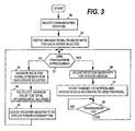
FIG. 3 is a flow diagram illustrating one embodiment of the performance control mechanism in a wireless communication terminal. In this embodiment, the performance control is carried out by controlling the sensitivity of the receiver. When operating in a network, such as a WLAN network, where terminals contend for the common air medium, the terminal first forms a dedicated communication group for itself by selecting one or more devices with which it needs to communicate and by establishing a communication link with each of the said devices (step 30). In an infrastructure network, only a neighboring access point is selected, while in an ad-hoc network the terminal may select one or more other terminals. The selection may be performed in various ways depending on the system involved. For example, the terminal may automatically detect the devices in the same network and present a list of the detected devices to the user, whereby the user may select the device(s) with which communication is preferred. The terminal may also include a prestored list of the devices in whose proximity the method of the invention is automatically initiated. - The terminal then defines a minimum signal-to-noise ratio for each of the selected devices, i.e. for each link (step 31). This is performed based on the link parameters to be used, such as the rate of the received data. If the link parameters to be used are not known, the minimum signal-to-noise ratio is defined assuming the worst case, i.e. the case in which the signal-to-noise ratio requirement is the highest possible. Furthermore, a performance or safety margin is defined for each minimum value in order to guarantee reliable transmission over the link.
- The terminal then decides whether the reception control mode or the media access control mode is to be entered. The decision is made based on whether or not the terminal needs to transmit soon (step 32).
- If the terminal does not have to transmit but may stay in a listening mode, the received signal strength is measured for each link to be listened to. The measured signal strength represents the average level of the signal input to the receiver of the terminal from the link in question (step 33).
- Based on the minimum signal-to-noise ratio, the associated performance margin, and the measured signal strength, the terminal then estimates the amount of maximum allowable total interference for each link separately (step 34). The ratio of the measured signal strength to the maximum allowable total interference then corresponds to a signal-to-noise ratio that exceeds the minimum signal-to-noise ratio by the said performance margin. The total interference here refers to receiver-originated interference, i.e. noise plus other unwanted components generated in the receiver.
- Based on the estimation, the receiver sensitivity may then be degraded in order to reduce the reception power needed in the terminal (step 35). In other words, by degrading the sensitivity of the receiver the power consumption of the receiver is reduced to a lower value in view of the signal-to-noise ratio required. If the selected devices are to be listened to simultaneously, the sensitivity value is determined by the link with the tightest sensitivity requirement, i.e. the link for which the amount of maximum allowable total interference is the smallest. However, if the terminal can listen to each selected device in a dedicated time window, the sensitivity value for a time window is determined by the link in question, and the sensitivity is changed to a new link-specific value when the link to be listened to is changed. In this respect the operation thus depends on the network in question.
- Since the local area networks are quite stable in short time periods, it is possible to degrade the sensitivity of the receiver based on the received signal strength value(s) measured from the device(s) with which communication is needed. If there are two or more such devices, the interference level requirement is defined separately for each device (link). However, the number of sensitivity levels used during listening periods depends on how many and which of the selected devices have to be listened to simultaneously.
- In the above-described manner the terminal thus restricts the operation range of its receiver to correspond to the area covered by the selected device(s), which may make the devices outside this area hidden nodes. However, this is not detrimental to the operation of the system since the terminal has only been receiving so far.
- When an own transmission is imminent, an indication of the need to transmit is generated and submitted to the process of the invention. As a result, the terminal enters the media access control mode in order to make all such devices "unhidden", which might be disturbed by the upcoming transmission (
step 32/yes). The indication may be obtained, for example, from the transmission buffers when the transmitter starts to assemble a packet or frame to be transmitted. In the media access control mode, the receiver sensitivity is adjusted so that the terminal is able to detect all nodes with which a collision might occur in the upcoming transmission phase, i.e. the terminal makes all such nodes "unhidden". In one embodiment, receiver sensitivity is adjusted to a maximum value (step 36) in order to minimize the risk of hidden nodes. The channel occupation is then sensed and the medium is accessed according to the medium access protocol used in the system in question (step 37). In IEEE 802.11 networks, for example, the Carrier Sense Multiple Access/Collision Avoidance (CSMA/CA) media access protocol is used to share a common channel. - The transmission power may be adjusted according to the link in question. When the transmission has been completed successfully, the process returns to adjust the receiver sensitivity for the listening mode (
steps 33 to 35). - In another embodiment of the invention, the sensitivity of the receiver is not adjusted to a maximum value at
step 36, but to a lower value that depends on the link in question. Depending on the link parameters, the terminal may first define a transmission power value sufficient for that link. A propagation path loss model may be used to estimate the area within which the upcoming transmission may disturb other devices. The sensitivity of the receiver may then be adjusted to a level sufficient to detect all (transmitting) nodes within that area, i.e. in a cell in which the upcoming transmission may cause interference. - The above sensitivity control allows several very small cells to be formed, which do not interfere with each other and which do not disturb the operation of the access point. For example, several laptop/handset pairs may operate simultaneously without disturbing each other.
- The group of communicating devices may be updated during the operation of the terminal. For example, the terminal may receive an indication that one of the selected devices enters or has entered sleep mode. If this link has been the one determining the sensitivity of the receiver, the sensitivity is changed according to the requirements of the rest of the selected devices. Furthermore, new devices may join the network and the terminal may select one or more of them to its communication group.
- As discussed above, the power consumption of the transceiver may also be reduced by controlling the dynamic range of the receiver.
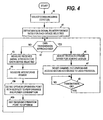
FIG. 4 is a flow diagram illustrating one embodiment of the control mechanism for controlling the dynamic range of the receiver. The embodiment ofFIG. 4 corresponds to that ofFIG. 3 , but in the two control modes discussed above the terminal controls the dynamic range of the receiver. In the reception control mode, the terminal measures the received signal strength for each link to be listened to (step 43), as instep 33 above. The terminal then measures the amount of interfering power indicative of the amount of external interference received by the receiver (step 44). In this embodiment, interference from outside interferers is thus taken into account. - The measured interfering power may be indicative of the total blocking power, i.e. the total power entering the active parts of the receiver, intermodulation power, or the power of an adjacent channel. Based on the minimum signal-to-interference ratio defined in
step 41, the associated performance margin, the measured signal strength, and the measured power value(s), the terminal then defines an optimum operation point with respect to performance and power consumption (step 45a), and sets the operation point to said optimum value (step 45b). The term operation point here refers generally to the internal transceiver settings yielding the desired dynamic range and power consumption. As discussed below, the settings may involve supply voltage settings and/or bias current settings, for example. - When the media access control mode is accessed, the terminal adjusts the dynamic range of the receiver to a maximum value (step 46) or to a lower value sufficient to detect all (transmitting) nodes within the area in which the upcoming transmission may cause interference. As in the case of sensitivity control, the transmission determined for the upcoming transmission may be used in defining said lower value.
-
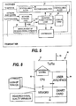
FIG. 5 is a block diagram illustrating one embodiment of the implementation of the performance control in a terminal. Ameasurement block 50 handles the measurement of the signal strength and supplies the measured value, such as RSSI, to a networkcontrol logic block 51, which calculates the maximum noise/interference allowed for the selected links. The network control logic may also receive other network parameters needed in the control process, such as the data rate used in the network. The calculated data is supplied to a receiver powercontrol logic block 52, which defines the internal control measures to be taken to change the sensitivity or the dynamic range of the receiver so that reduced power consumption is achieved. The receiver power control logic block then controls the components in thereceiver signal path 54 to obtain the desired sensitivity or dynamic range coupled with the desired power consumption. The receiver power control logic block may also control thesynthesizer 53 of the transceiver, which also contains power consuming components. The indication of an approaching transmission may be given to the network control logic block, for example, which then controls the receiver power control logic to assume the media access control mode. The receiver may also be divided intocontrollable blocks 56. Each of the blocks may be controlled separately, as discussed below in connection withFIG. 6 . - The receiver power control logic block may be provided with one or more look-up tables 55 which map the needed change in the sensitivity or dynamic range to the internal control mechanism to be used. It is also possible that the measured signal strength value is mapped directly to the internal control mechanism in the look-up table. Therefore, the measured signal strength value may also be supplied directly to the receiver power control logic, as indicated by a dashed arrow in the figure. The internal control mechanism thus indicates the operation points discussed above.
- The sensitivity or the dynamic range of the receiver may be controlled in various ways depending on the structure of the receiver. Different blocks in the receiver signal path may be controlled to achieve the desired level of sensitivity or dynamic range coupled with desired power consumption. For example, the gain of a low-noise front-end amplifier (LNA) and/or the resolution of an analog-to-digital converter may be controlled. Circuit-level power save mechanisms that may be utilized in the present invention are described in U.S. Patent Applications
US2003/0124999 A1 andUS2003/0078007 A1 . Generally, receiver power consumption may be reduced in a great number of ways. To give examples, power consumption may be controlled by changing various biasing currents or supply voltages in the receiver, by-passing one or more of the receiver stages, selecting a signal path with a lower/higher power consumption, and/or shutting down components with high power consumption. Especially the control of bias currents and the selection of different signal paths are effective techniques for reducing power consumption. The measurements needed for the control may be made either with analog domain power detectors or with digital measurement structures. They provide the necessary information to the control logic that steers the power consumption of receiver blocks. -
FIG. 6 illustrates one embodiment of a control mechanism for controlling the performance of the receiver in the reception control mode. In this embodiment, the variable(s) measured based on received packets are first used to determine the gain of the receiver chain (step 60) and other receiver performance requirements referred to the antenna port or the RF input of the terminal (step 61). As discussed above, the variable(s) to be measured depend on whether sensitivity or dynamic range is controlled. In both embodiments, the received signal strength is measured, and the interfering power is additionally measured in the case of dynamic range control. The receiver is divided into several controllable blocks and the gain and receiver requirements are then partitioned between different receiver blocks atstep 62. Each receiver block may then be controlled according to its requirements (step 63). The internal control information may again be retrieved from one or more look-up tables, for example. Each controllable block may include one or more low-noise amplifiers, down-conversion mixers, baseband or IF amplifiers, analog-to-digital converters, local oscillator buffers, or voltage controlled oscillators. As discussed above, the synthesizer of the transceiver may also be controlled to reduce power consumption. - The terminal then checks if the set performance level is sufficient, i.e. if packets are received correctly (step 64). If this is the case, the terminal waits for the next packet (step 66) and repeats the above steps, i.e. measures the variables and controls the different receiver blocks according to their requirements. If the performance is not sufficient, the terminal increases the performance margin (step 65) and waits for the next packet before repeating the above steps.
-
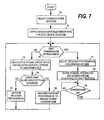
FIG. 7 illustrates an embodiment of the invention, in which error rate is used as the signal quality variable measured from the selected device(s). In this embodiment, a minimum bit or frame error rate is defined for each of the selected devices, i.e. for each link (step 71). In the reception control mode, the terminal then calculates the bit or frame error rate value for those selected devices that are to be listened to simultaneously (step 72). If the calculated error rates are greater than the corresponding minimum values, the performance of the receiver, such as receiver sensitivity, may be degraded to reduce power consumption (step 76). The performance may be degraded based on the device, whose error rate is closest to the respective minimum value. If any of the error rate values is below the corresponding minimum value, the performance of the receiver is improved (step 75). The media access control mode is similar to that discussed in connection withFIG. 3 . -
FIG. 8 illustrates the basic elements of the mobile terminal according to one embodiment of the invention. Themobile terminal 80 comprises atransceiver 81 provided with at least oneantenna 82, a control unit 83, user interface means 84 for creating a user interface through which the user can operate the terminal, and memory means 85, which may include one or more smart cards 86, such as one of the above-mentioned identity modules. However, as discussed above, an identity module is not included in a traditional WLAN terminal. The control unit performs the above-described control functions of the invention, i.e. it contains the control logic blocks shown inFIG. 5 and controls the transceiver as shown by an arrow in the figure. The memory means include the MAC MIB or a similar database, which may include the control information needed for the performance control, such as the measured signal strength or error rate values, and the look-up table(s) indicating the internal control operations for controlling the performance and the power consumption according to the measured signal quality variables. The control unit obtains the signal quality variables from the transceiver and stores them in the memory. - The data processing environment of the control unit may resemble that of an ordinary PC, and if an existing wireless terminal is provided with suitable interfaces for receiver sensitivity control, the control mechanism of the invention may be introduced separately into an existing terminal, for example in a multimedia card. It is also possible that the control mechanism, i.e. the program code that causes the control unit to control the performance of the receiver in the above-described manner, is delivered as a separate plug-in software module which may be downloaded to the terminal via the network.
- The above-described embodiments for controlling the sensitivity and the dynamic range of the receiver may also be combined so that sensitivity is controlled when there are no strong external interferers and dynamic range is controlled when such interferers exist in the neighborhood of the terminal.
- Although the invention was described above with reference to the examples shown in the appended drawings, it is obvious that the invention is not limited to these, but may be modified by those skilled in the art without departing from the scope and spirit of the invention. As discussed above, the invention may be utilized in any networks in which a media access control mechanism includes a function resembling the IEEE 802.11 Distributed Coordination Function (DCF). The invention may therefore also be used in systems having a centralized media access control, if the centralized control is not used unceasingly. Furthermore, different physical transmission techniques, such as Ultra Wide-Band (UWB) or Bluetooth, may be used in such networks. The performance of the receiver may also be controlled in any manner allowing performance degradation to be implemented so that transceiver power consumption is reduced.
Claims (44)
- A method for decreasing power consumption in a wireless communication terminal (120), the method comprising the steps of:- selecting (30) at least one communication device as a communicating peer in a wireless communication system;- measuring (33) a signal quality variable from at least one of the at least one communication device selected in the selecting step, each signal quality variable being measured based on a signal received from a respective one of the at least one communication device selected in the selecting step, whereby at least one signal quality variable is obtained;- adjusting (35) receiver performance based on at least one of the at least one signal quality variable obtained in the measuring step, the adjusting step being performed for reducing power consumption while ensuring reception of respective signals from the at least one communication device selected in the selecting step;- monitoring (32) if the wireless communication terminal's (120) own transmission is approaching; and- readjusting (36) receiver performance for determining availability of a common air medium at a performance level enabling detection of transmitting communication devices within a coverage area of said own transmission, the readjusting step being performed when the monitoring step indicates that said own transmission is approaching.
- A method according to claim 1, wherein the adjusting and readjusting steps (33, 36) include adjusting receiver sensitivity.
- A method according to claim 1, wherein the measuring step (33) includes measuring the signal quality variable from each of the at least one communication device, and wherein each signal quality variable measured is indicative of signal strength received from the corresponding communication device.
- A method according to claim 3, further comprising a step of determining a device-specific signal-to-noise-ratio for each of the at least one communication device, each device-specific signal-to-noise-ratio indicating a signal-to-noise ratio value required to listen to the communication device concerned.
- A method according to claim 4, further comprising a step of defining a maximum amount of receiver noise allowed for each of the at least one communication device, wherein the maximum amount of receiver noise allowed for a communication device is defined based on the minimum signal-to-noise-ratio determined for that device in the determining step and on the received signal strength measured for that device in the measuring step.
- A method according to claim 5, wherein the selecting step (30) includes selecting a plurality of communication devices.
- A method according to claim 6, further comprising a step of choosing one of the plurality of communication devices, the choosing step being performed based on the maximum amount of receiver noise defined for the at least one communication device in the defining step.
- A method according to claim 7, wherein the adjusting step (35) includes adjusting the receiver sensitivity based on the chosen communication device only, the adjusting being performed for listening to said plurality of communication devices.
- A method according to claim 6, wherein the adjusting step (35) includes adjusting receiver sensitivity based on one of the plurality of communication devices at a time.
- A method according to claim 2, wherein the readjusting step (36) includes maximizing receiver sensitivity.
- A method according to claim 1, further comprising a step of determining transmission power for said own transmission.
- A method according to claim 11, wherein the readjusting step (36) includes a sub-step of determining receiver sensitivity based on the transmission power determined.
- A method according to claim 12, further comprising the steps of:- determining the availability of the common air medium using the sensitivity determined in the determining sub-step; and- performing said own transmission.
- A method according to claim 1, further comprising a step of defining interfering power received in the communication terminal (120), the interfering power being indicative of a level of interference caused by external interferers.
- A method according to claim 14, wherein the adjusting and readjusting steps include adjusting the dynamic range of the receiver.
- A method according to claim 14, wherein the defining step includes defining the total co-channel power.
- A method according to claim 14, wherein the defining step includes defining the intermodulation power.
- A method according to claim 14, wherein the defining step includes defining the power of an adjacent channel.
- A method according to claim 15, further comprising a step of determining a device-specific signal-to-interference-ratio for each of the at least one communication device, each device-specific signal-to-interference-ratio indicating a signal-to-interference ratio value required to listen to the communication device concerned.
- A method according to claim 19, wherein the adjusting step includes adjusting the dynamic range based on the interfering power defined in the defining step and on the device-specific signal-to-interference ratio of one of the at least one communication device.
- A method according to claim 1, wherein the selecting step (30) includes selecting an access point as the communicating peer.
- A method according to claim 1, wherein the selecting step (30) includes selecting at least one other wireless communication terminal as the communicating peer.
- A method according to claim 4, wherein the determining step includes determining the device-specific signal-to-noise ratio for each of the at least one communication device by calculating a minimum signal-to-noise ratio for each of the at least one wireless communication device and adding a predetermined safety margin to the minimum signal-to-noise ratio.
- A method according to claim 19, wherein the determining step includes determining the device-specific signal-to-interference ratio for each of the at least one communication device by calculating a minimum signal-to-interference ratio for each of the at least one wireless communication device and adding a predetermined safety margin to the minimum signal-to-interference ratio.
- A method according to claim 1, wherein the adjusting step (35) includes at least one operation from a group including reduction of a biasing current, reduction of a supply voltage, and by-pass of a selected receiver stage.
- A method according to claim 1, wherein the adjusting step (35) includes a sub-step of controlling several receiver blocks, each block being controlled separately.
- A method according to claim 26, wherein the controlling sub-step includes retrieving control information for each block from a look-up table (55).
- A method according to claim 26, wherein the controlling sub-step includes calculating control information in order to minimize power consumption.
- A method according to claim 1, wherein the measuring step (33) includes measuring the signal quality variable from each of the at least one communication device, and wherein each signal quality variable is indicative of an error rate of a signal received from the corresponding communication device.
- A wireless communication terminal (120) for a wireless communication system, the wireless communication terminal (120) comprising:- selection means (51, 83) for selecting at least one communication device as a communicating peer in the communication system;- first measurement means (50) for measuring a signal quality variable from at least one of the at least one communication device, each signal quality variable being measured based on a signal received from a respective one of the at least one communication device, whereby at least one signal quality variable is obtained;- first performance control means (52, 83) for adjusting receiver performance based on at least one of the at least one signal quality variable, thereby to permit the wireless communication terminal (120) to receive respective signals from the at least one communication device with reduced power consumption;- monitoring means (51, 83) for monitoring if the wireless communication terminal's (120) own transmission is approaching; and- second performance control means (52, 83) for adjusting receiver performance to a performance level enabling the terminal (120) to detect transmitting communication devices within a coverage area of said own transmission, the second performance control means being (52, 83) configured to operate when the monitoring means (51, 83) indicate that said own transmission is approaching.
- A wireless communication terminal (120) according to claim 30, wherein the first and second performance control means (52, 83) are configured to control receiver sensitivity.
- A wireless communication terminal (120) according to claim 31, wherein the at least one signal quality variable is indicative of signal strength.
- A wireless communication terminal (120) according to claim 32, further comprising calculation means (51, 83) for calculating a device-specific signal-to-noise-ratio for each of the at least one communication device, each device-specific signal-to-noise-ratio indicating a signal-to-noise ratio value required to listen to the communication device concerned.
- A wireless communication terminal (120) according to claim 33, wherein the first performance control means (52, 83) are configured to define a maximum amount of receiver noise allowed for each of the at least one communication device based on the device-specific signal-to-noise ratio determined for that device and on the received signal strength measured for that device.
- A wireless communication terminal (120) according to claim 31, wherein the first performance control means are further configured to choose one of the at least one communication device and to adjust receiver sensitivity based on the maximum amount of receiver noise allowed for that device.
- A wireless communication terminal (120) according to claim 31, wherein the second performance control means (52, 83) are configured to maximize the receiver sensitivity if the wireless communication terminal's (120) own transmission is approaching.
- A wireless communication terminal (120) according to claim 31, wherein the second performance control means (52, 83) are configured to determine receiver sensitivity based on transmission power defined for said own transmission.
- A wireless communication terminal (120) according to claim 30, wherein the first performance control means (52, 83) are provided with a look-up table (55) indicating internal control measures to be taken.
- A wireless communication terminal (120) according to claim 30, wherein the second performance control means (52, 83) are provided with a look-up table (55) indicating internal control measures to be taken.
- A wireless communication terminal (120) according to claim 30, further comprising second measurement means for measuring interfering power received in the communication terminal (120), the interfering power being indicative of a level of interference caused by external interferers.
- A wireless communication terminal (120) according to claim 40, wherein the first and second performance control means (52, 83) are configured to control the receiver dynamic range.
- A wireless communication terminal (120) according to claim 41, wherein the first performance control means (52, 83) are further configured to choose one of the at least one communication device and to adjust the dynamic range based on the interfering power and the signal quality variable corresponding to the chosen device.
- A wireless communication terminal (120) according to claim 30, wherein the at least one signal quality variable is indicative of an error rate of a signal measured from the corresponding communication device.
- A computer useable medium (85) having computer readable program code embodied therein to control a wireless communication terminal (120), the computer readable program code comprising:- a first computer readable program code portion for causing at least one communication device to be selected as a communicating peer for the wireless communication terminal (120);- a second computer readable program code portion for causing the wireless communication terminal (120) to adjust receiver performance based on a signal quality variable measured based on a signal received from at least one of the at least one wireless communication device;- a third computer readable program code portion for causing the wireless communication terminal (120) to generate an indication when the wireless communication terminal's (120) own transmission is approaching; and- a fourth computer readable program code portion for causing the wireless communication terminal (120) to adjust receiver performance to a level enabling the wireless communication terminal (120) to detect transmitting communication devices within a coverage area of said own transmission, the fourth computer readable program code portion operating in response to the indication that said own transmission is approaching.
Applications Claiming Priority (1)
| Application Number | Priority Date | Filing Date | Title |
|---|---|---|---|
| PCT/FI2004/000617 WO2006040390A1 (en) | 2004-10-15 | 2004-10-15 | Reduction of power consumption in wireless communication terminals |
Publications (2)
| Publication Number | Publication Date |
|---|---|
| EP1806017A1 EP1806017A1 (en) | 2007-07-11 |
| EP1806017B1 true EP1806017B1 (en) | 2012-07-25 |
Family
ID=36148072
Family Applications (1)
| Application Number | Title | Priority Date | Filing Date |
|---|---|---|---|
| EP04791417A Active EP1806017B1 (en) | 2004-10-15 | 2004-10-15 | Reduction of power consumption in wireless communication terminals |
Country Status (4)
| Country | Link |
|---|---|
| US (1) | US10296064B2 (en) |
| EP (1) | EP1806017B1 (en) |
| CN (1) | CN101044776B (en) |
| WO (1) | WO2006040390A1 (en) |
Families Citing this family (30)
| Publication number | Priority date | Publication date | Assignee | Title |
|---|---|---|---|---|
| WO2006040390A1 (en) | 2004-10-15 | 2006-04-20 | Nokia Corporation | Reduction of power consumption in wireless communication terminals |
| US8711816B2 (en) | 2005-03-04 | 2014-04-29 | Nokia Corporation | Link establishment in a wireless communication environment |
| US7634290B2 (en) * | 2005-05-31 | 2009-12-15 | Vixs Systems, Inc. | Adjusting transmit power of a wireless communication device |
| WO2007013614A1 (en) * | 2005-07-28 | 2007-02-01 | Kyocera Corporation | Communication method, communication system, and communication terminal |
| GB2443099B (en) * | 2005-11-11 | 2008-10-08 | Realtek Semiconductor Corp | Power consumption control methods applied to communication systems |
| TWI279994B (en) | 2005-11-11 | 2007-04-21 | Realtek Semiconductor Corp | Power consumption control methods applied to communication systems, and related devices |
| US20090029652A1 (en) * | 2007-07-25 | 2009-01-29 | Kai Xie | Adjusting power consumption of mobile communication devices based on received signal quality |
| US20090061919A1 (en) * | 2007-09-04 | 2009-03-05 | Broadcom Corporation | Power consumption management based on transmit power control data and method for use therewith |
| WO2009098628A1 (en) * | 2008-02-05 | 2009-08-13 | Philips Intellectual Property & Standards Gmbh | Controlling the power consumption of a receiving unit |
| US8271014B2 (en) * | 2008-08-11 | 2012-09-18 | Qualcomm Incorporated | Automated parameter adjustment to compensate self adjusting transmit power and sensitivity level at the node B |
| US9867020B2 (en) | 2008-09-15 | 2018-01-09 | Microsoft Technology Licensing, Llc | Pre-determined responses for wireless devices |
| US8112649B2 (en) * | 2009-03-17 | 2012-02-07 | Empire Technology Development Llc | Energy optimization through intentional errors |
| WO2010123573A1 (en) * | 2009-04-23 | 2010-10-28 | Maxlinear, Inc. | Channel-sensitive power control |
| JP5371585B2 (en) * | 2009-07-03 | 2013-12-18 | キヤノン株式会社 | COMMUNICATION DEVICE, COMMUNICATION DEVICE CONTROL METHOD, PROGRAM |
| US8744511B2 (en) * | 2009-09-04 | 2014-06-03 | Qualcomm Incorporated | Output power control for advanced WLAN and bluetooth-amp systems |
| JP5221617B2 (en) * | 2010-09-24 | 2013-06-26 | 株式会社東芝 | COMMUNICATION DEVICE, COMMUNICATION SYSTEM, CONTROL METHOD, AND PROGRAM |
| JPWO2012057094A1 (en) * | 2010-10-25 | 2014-05-12 | 和浩 山本 | Communication device |
| US20120184313A1 (en) * | 2011-01-19 | 2012-07-19 | Henry Ptasinski | Method and System for Medium Access with Reduced Power Consumption for Constrained Wireless Devices |
| EP2528021B1 (en) | 2011-05-27 | 2015-02-25 | Nxp B.V. | Control system for controlling the power consumption of an electronic device |
| US8909267B2 (en) * | 2012-04-19 | 2014-12-09 | Telefonaktiebolaget L M Ericsson (Publ) | Energy-efficient detection of network connection requests |
| US9408153B2 (en) * | 2012-08-09 | 2016-08-02 | Nokia Technologies Oy | Controlling a mobile device |
| US9144109B2 (en) * | 2012-12-20 | 2015-09-22 | Intel Corporation | Methods and systems for multi-directional time preservation distribution in multi-communication core devices |
| US8923452B2 (en) | 2013-03-18 | 2014-12-30 | Lockheed Martin Corporation | Noise-based gain adjustment and amplitude estimation system |
| EP3454594B1 (en) | 2013-06-11 | 2020-11-04 | Seven Networks, LLC | Offloading application traffic to a shared communication channel for signal optimisation in a wireless network for traffic utilizing proprietary and non-proprietary protocols |
| US9386542B2 (en) * | 2013-09-19 | 2016-07-05 | Google Technology Holdings, LLC | Method and apparatus for estimating transmit power of a wireless device |
| CN104618039B (en) * | 2015-01-27 | 2017-10-10 | 南京航空航天大学 | A kind of algorithm and receiver for adjusting receiver performance in real time according to communication condition |
| US10129131B2 (en) * | 2015-06-30 | 2018-11-13 | Dell Products, Lp | System and method for device optimization in a network of devices with embedded electronics |
| US9924463B2 (en) * | 2016-08-29 | 2018-03-20 | Mediatek Singapore Pte. Ltd. | Method, system and apparatus for controlling power consumption of a mobile terminal |
| CN111142651B (en) * | 2019-05-09 | 2021-07-23 | 广东小天才科技有限公司 | System switching method of communication terminal and communication terminal |
| US20230086121A1 (en) * | 2021-09-22 | 2023-03-23 | Apple Inc. | Transmission power control |
Family Cites Families (73)
| Publication number | Priority date | Publication date | Assignee | Title |
|---|---|---|---|---|
| US5949776A (en) | 1990-01-18 | 1999-09-07 | Norand Corporation | Hierarchical communication system using premises, peripheral and vehicular local area networking |
| JPH08289366A (en) * | 1995-04-13 | 1996-11-01 | Hitachi Ltd | Moving body communication system |
| JP3180726B2 (en) | 1997-08-05 | 2001-06-25 | 日本電気株式会社 | Mobile terminal control method |
| SE518376C2 (en) * | 1997-10-20 | 2002-10-01 | Ericsson Telefon Ab L M | Method and apparatus in a radio communication network |
| US6498926B1 (en) | 1997-12-09 | 2002-12-24 | Qualcomm Incorporated | Programmable linear receiver having a variable IIP3 point |
| US7283797B1 (en) * | 1998-03-06 | 2007-10-16 | Ericsson Inc. | System and method of improving the dynamic range of a receiver in the presence of a narrowband interfering signal |
| US6484027B1 (en) * | 1998-06-15 | 2002-11-19 | Sbc Technology Resources, Inc. | Enhanced wireless handset, including direct handset-to-handset communication mode |
| US6766143B1 (en) | 1999-01-25 | 2004-07-20 | Robert W. Beckwith | Expanded capabilities for wireless two-way packet communications for intelligent electronic devices (IEDs) |
| US6542517B1 (en) | 1999-05-11 | 2003-04-01 | Qualcomm Incorporated | System and method for operating a mobile station in voice mode or pager mode |
| JP2001189736A (en) * | 1999-12-28 | 2001-07-10 | Fujitsu Ltd | Lan interface device and method for controlling frame transmission and reception |
| US7054329B2 (en) | 2000-07-07 | 2006-05-30 | Koninklijke Philips Electronics, N.V. | Collision avoidance in IEEE 802.11 contention free period (CFP) with overlapping basic service sets (BSSs) |
| US6452910B1 (en) | 2000-07-20 | 2002-09-17 | Cadence Design Systems, Inc. | Bridging apparatus for interconnecting a wireless PAN and a wireless LAN |
| US6895255B1 (en) | 2000-10-20 | 2005-05-17 | Symbol Technologies, Inc. | Dual mode wireless data communications |
| EP1338125A2 (en) | 2000-11-03 | 2003-08-27 | AT & T Corp. | Tiered contention multiple access (tcma): a method for priority-based shared channel access |
| US7305004B2 (en) | 2001-01-16 | 2007-12-04 | At&T Corp. | Interference suppression methods for 802.11 |
| US7023824B2 (en) * | 2001-02-27 | 2006-04-04 | Telefonaktiebolaget L M Ericsson (Publ) | Method, apparatus, and system for optimizing transmission power and bit rate in multi-transmission scheme communication systems |
| US7046650B2 (en) | 2001-03-02 | 2006-05-16 | At&Tcorp. | Interference suppression methods for 802.11 |
| US7151759B1 (en) * | 2001-03-19 | 2006-12-19 | Cisco Systems Wireless Networking (Australia) Pty Limited | Automatic gain control and low power start-of-packet detection for a wireless LAN receiver |
| US7177294B2 (en) | 2001-03-22 | 2007-02-13 | Oxford Semiconductor, Inc. | Collision rectification in wireless communication devices |
| US7164671B2 (en) | 2001-12-27 | 2007-01-16 | Koninklijke Philips Electronics N.V. | Overlapping network allocation vector (ONAV) for avoiding collision in the IEEE 802.11 WLAN operating under HCF |
| US7194263B2 (en) | 2001-09-17 | 2007-03-20 | Microsoft Corporation | System and method for concurrent operation of a wireless device in two disjoint wireless networks |
| US7248570B2 (en) | 2001-09-17 | 2007-07-24 | Microsoft Corporation | System and method for coordinating bandwidth usage of a communication channel by wireless network nodes |
| US6993291B2 (en) | 2001-10-11 | 2006-01-31 | Nokia Corporation | Method and apparatus for continuously controlling the dynamic range from an analog-to-digital converter |
| JP3625280B2 (en) * | 2001-11-02 | 2005-03-02 | 松下電器産業株式会社 | COMMUNICATION METHOD, COMMUNICATION DEVICE, AND COMMUNICATION SYSTEM |
| US7299021B2 (en) | 2001-12-28 | 2007-11-20 | Nokia Corporation | Method and apparatus for scaling the dynamic range of a receiver for continuously optimizing performance versus power consumption |
| US6647273B2 (en) * | 2001-12-28 | 2003-11-11 | Nokia Corporation | Method and apparatus for reducing power consumption in transceivers in wireless communications systems having a power control loop |
| US7471667B2 (en) | 2002-01-09 | 2008-12-30 | Nxp B.V. | Coexistence of modulation schemes in a WLAN |
| US7515557B1 (en) * | 2002-01-11 | 2009-04-07 | Broadcom Corporation | Reconfiguration of a communication system |
| US6977944B2 (en) | 2002-01-12 | 2005-12-20 | Conexant, Inc. | Transmission protection for communications networks having stations operating with different modulation formats |
| SE0200142D0 (en) | 2002-01-17 | 2002-01-17 | Pro Forma Delta Ab | A selection system for enabling a selection of locally registered service providers in mobile telecommunication devices |
| US6980823B2 (en) * | 2002-01-31 | 2005-12-27 | Qualcomm Inc. | Intermediate wake mode to track sleep clock frequency in a wireless communication device |
| US20040229566A1 (en) | 2003-05-13 | 2004-11-18 | Weilin Wang | Systems and methods for congestion control in a wireless mesh network |
| US7742443B2 (en) | 2002-05-28 | 2010-06-22 | Maarten Menzo Wentink | Transmit power management in shared-communications channel networks |
| JP3792632B2 (en) | 2002-10-01 | 2006-07-05 | Necインフロンティア株式会社 | Wireless LAN communication system |
| KR100470070B1 (en) | 2002-12-20 | 2005-02-05 | 한국전자통신연구원 | System for packet bridging between access points of wireless LAN and method thereof, its program storing recording medium |
| US20040128574A1 (en) * | 2002-12-31 | 2004-07-01 | Franco Ricci | Reducing integrated circuit power consumption |
| US7774495B2 (en) * | 2003-02-13 | 2010-08-10 | Oracle America, Inc, | Infrastructure for accessing a peer-to-peer network environment |
| US7382765B2 (en) * | 2003-04-30 | 2008-06-03 | Harris Corporation | Predictive routing in a moble ad hoc network |
| EP1478131A1 (en) | 2003-05-12 | 2004-11-17 | Siemens Aktiengesellschaft | Method for random access in a lokal network |
| JP4339313B2 (en) | 2003-05-15 | 2009-10-07 | 三菱電機株式会社 | Communication method, wireless terminal and base station |
| US7397785B2 (en) | 2003-05-28 | 2008-07-08 | Nokia Corporation | Method for enhancing fairness and performance in a multihop ad hoc network and corresponding system |
| KR100716968B1 (en) | 2003-06-19 | 2007-05-10 | 삼성전자주식회사 | Method and apparatus for wireless communication in wire/wireless complex communication device |
| US20050025104A1 (en) | 2003-07-30 | 2005-02-03 | Fischer Michael Andrew | Managing coexistence of separate protocols sharing the same communications channel |
| EP1652347B1 (en) | 2003-08-06 | 2007-11-28 | Matsushita Electric Industrial Co., Ltd. | Master station of communication system and access control method |
| EP1530316A1 (en) | 2003-11-10 | 2005-05-11 | Go Networks | Improving the performance of a wireless packet data communication system |
| US20050100029A1 (en) | 2003-11-12 | 2005-05-12 | Research Foundation Of The State University Of New York | Ad hoc network routing for hotspot mitigation and load balancing in wireless LANs |
| US7313378B2 (en) * | 2003-11-26 | 2007-12-25 | Starkey Laboratories, Inc. | Tracking automatic gain control |
| US7336923B2 (en) | 2003-12-03 | 2008-02-26 | Intel Corporation | Method, apparatus and system for extending wireless network coverage |
| TWI227978B (en) | 2003-12-05 | 2005-02-11 | Kye Systems Corp | Transmission method of dual mode coexisted wireless local area network |
| US7463644B2 (en) * | 2003-12-11 | 2008-12-09 | Intel Corporation | Self-configuring physical carrier sensing threshold adaptation |
| US7359727B2 (en) * | 2003-12-16 | 2008-04-15 | Intel Corporation | Systems and methods for adjusting transmit power in wireless local area networks |
| US7352772B2 (en) | 2003-12-19 | 2008-04-01 | Lenovo Singapore Pte. Ltd. | Minimization of performance impact in overlying 802.11b and 802.11g networks |
| US7389352B2 (en) | 2003-12-24 | 2008-06-17 | Lenovo Singapore Pte. Ltd | System and method for concurrent WLAN and WPAN wireless modes from a single device |
| JP4005974B2 (en) | 2004-01-09 | 2007-11-14 | 株式会社東芝 | COMMUNICATION DEVICE, COMMUNICATION METHOD, AND COMMUNICATION SYSTEM |
| JP2007533173A (en) | 2004-02-02 | 2007-11-15 | コーニンクレッカ フィリップス エレクトロニクス エヌ ヴィ | An improved network allocation vector mechanism for optimal reuse of frequency bands in wireless communication systems |
| US8744516B2 (en) | 2004-02-05 | 2014-06-03 | Sri International | Generic client for communication devices |
| US9001800B2 (en) | 2004-02-06 | 2015-04-07 | Koninklijke Philips N.V. | System and method for an ultra wide-band medium access control distributed reservation protocol |
| US7680059B2 (en) | 2004-02-13 | 2010-03-16 | Broadcom Corporation | Multiple protocol wireless communications in a WLAN |
| JP4000122B2 (en) | 2004-02-27 | 2007-10-31 | 株式会社東芝 | Wireless communication system and wireless communication method |
| US7664130B2 (en) | 2004-03-01 | 2010-02-16 | Sony Corporation | Wireless communication system, wireless communication apparatus, wireless communication method and computer program |
| JP4266192B2 (en) | 2004-03-05 | 2009-05-20 | 株式会社東芝 | Wireless communication apparatus and wireless communication method |
| US7542452B2 (en) | 2004-04-09 | 2009-06-02 | Sharp Laboratories Of America, Inc. | Systems and methods for implementing an enhanced multi-channel direct link protocol between stations in a wireless LAN environment |
| US7171179B2 (en) * | 2004-06-28 | 2007-01-30 | Broadcom Corporation | Adjustment of a received signal strength indication module |
| CN1871816A (en) | 2004-06-29 | 2006-11-29 | 三菱电机株式会社 | Radio terminal station and radio communication system |
| KR100630355B1 (en) | 2004-08-04 | 2006-09-29 | 한국전자통신연구원 | Apparatus and method for providing frame bridge of wireless local area network |
| US7680087B2 (en) | 2004-09-08 | 2010-03-16 | Canon U.S.A., Inc. | Wireless state machine and multiplexing method for concurrent ad-hoc and infrastructure mode service in wireless networking |
| US7570972B2 (en) | 2004-10-05 | 2009-08-04 | Dell Products L.P. | Scheme and algorithm to form direct links |
| WO2006040390A1 (en) | 2004-10-15 | 2006-04-20 | Nokia Corporation | Reduction of power consumption in wireless communication terminals |
| US7330696B2 (en) | 2004-11-24 | 2008-02-12 | Symbol Technologies, Inc. | System and method for multi-mode radio operation |
| US7486932B2 (en) | 2005-02-25 | 2009-02-03 | Nokia Corporation | Method and system for VoIP over WLAN to bluetooth headset using advanced eSCO scheduling |
| US8711816B2 (en) | 2005-03-04 | 2014-04-29 | Nokia Corporation | Link establishment in a wireless communication environment |
| US7634290B2 (en) * | 2005-05-31 | 2009-12-15 | Vixs Systems, Inc. | Adjusting transmit power of a wireless communication device |
| US9031054B2 (en) * | 2010-07-09 | 2015-05-12 | Nokia Corporation | Reservation response and multi-user transmissions |
-
2004
- 2004-10-15 WO PCT/FI2004/000617 patent/WO2006040390A1/en active Application Filing
- 2004-10-15 US US11/664,483 patent/US10296064B2/en active Active
- 2004-10-15 CN CN2004800442317A patent/CN101044776B/en active Active
- 2004-10-15 EP EP04791417A patent/EP1806017B1/en active Active
Also Published As
| Publication number | Publication date |
|---|---|
| WO2006040390A1 (en) | 2006-04-20 |
| CN101044776B (en) | 2010-12-15 |
| EP1806017A1 (en) | 2007-07-11 |
| US20080108397A1 (en) | 2008-05-08 |
| CN101044776A (en) | 2007-09-26 |
| US10296064B2 (en) | 2019-05-21 |
Similar Documents
| Publication | Publication Date | Title |
|---|---|---|
| EP1806017B1 (en) | Reduction of power consumption in wireless communication terminals | |
| CN1771693B (en) | Method, device for controlling power consumption in short-range wireless terminals and short range wireless communication system | |
| JP5024881B2 (en) | System and method for global power control | |
| KR101527287B1 (en) | Method and apparatus for selecting a multi-band access point to associate with a multi-band mobile station | |
| US6845232B2 (en) | Analog peak detection circuitry for radio receivers | |
| Ebert et al. | An energy-efficient power control approach for WLANs | |
| US9060340B2 (en) | Re-configurable communication device and managing method thereof | |
| KR101287648B1 (en) | Terminal transmit power control with link adaptation | |
| KR100582727B1 (en) | Transmit power control system and method in wireless lan | |
| EP1672468B1 (en) | Power management for ultra wide band (uwb) devices | |
| US20050079842A1 (en) | Timing based LNA gain adjustment in an RF receiver to compensate for intermodulation interference | |
| US7689843B2 (en) | Ultra wide band power save | |
| US7110736B2 (en) | Analog peak detection circuitry for radio receivers | |
| RU2332814C2 (en) | Of selection access point in wireless communication system | |
| EP2480031B1 (en) | Reducing WLAN power consumption on a mobile device utilizing a cellular radio interface | |
| US6661999B1 (en) | System for increasing RF power as a constant over a temperature range and employing reduced transmitter current drain during low power output periods | |
| JP2003332973A (en) | Wireless communication device | |
| Monks et al. | Energy saving and capacity improvement potential of power control in multi-hop wireless networks | |
| KR100954763B1 (en) | Reduction of power consumption in wireless communication terminals | |
| Frantti | Expert system for open-loop power control of wireless local area networks | |
| KR100766130B1 (en) | Adaptive power save mode for short-range wireless terminals | |
| WO2005006659A1 (en) | Reduction of power consumption in wireless terminals | |
| Kowalik et al. | An evaluation of a conservative transmit power control mechanism on an indoor 802.11 wireless mesh testbed | |
| Jiang et al. | Analysis on deployment parameters of secondary users in cognitive radio networks | |
| Zhang | Transmission Power Adaptation Using Link Quality Estimation In IEEE802. 11 |
Legal Events
| Date | Code | Title | Description |
|---|---|---|---|
| PUAI | Public reference made under article 153(3) epc to a published international application that has entered the european phase |
Free format text: ORIGINAL CODE: 0009012 |
|
| 17P | Request for examination filed |
Effective date: 20070509 |
|
| AK | Designated contracting states |
Kind code of ref document: A1 Designated state(s): AT BE BG CH CY CZ DE DK EE ES FI FR GB GR HU IE IT LI LU MC NL PL PT RO SE SI SK TR |
|
| DAX | Request for extension of the european patent (deleted) | ||
| 17Q | First examination report despatched |
Effective date: 20091016 |
|
| REG | Reference to a national code |
Ref country code: DE Ref legal event code: R079 Ref document number: 602004038676 Country of ref document: DE Free format text: PREVIOUS MAIN CLASS: H04Q0007320000 Ipc: H04W0052020000 |
|
| RIC1 | Information provided on ipc code assigned before grant |
Ipc: H04W 52/02 20090101AFI20120105BHEP |
|
| GRAP | Despatch of communication of intention to grant a patent |
Free format text: ORIGINAL CODE: EPIDOSNIGR1 |
|
| GRAS | Grant fee paid |
Free format text: ORIGINAL CODE: EPIDOSNIGR3 |
|
| GRAA | (expected) grant |
Free format text: ORIGINAL CODE: 0009210 |
|
| AK | Designated contracting states |
Kind code of ref document: B1 Designated state(s): AT BE BG CH CY CZ DE DK EE ES FI FR GB GR HU IE IT LI LU MC NL PL PT RO SE SI SK TR |
|
| REG | Reference to a national code |
Ref country code: GB Ref legal event code: FG4D |
|
| REG | Reference to a national code |
Ref country code: CH Ref legal event code: EP Ref country code: DE Ref legal event code: R081 Ref document number: 602004038676 Country of ref document: DE Owner name: NOKIA TECHNOLOGIES OY, FI Free format text: FORMER OWNER: NOKIA CORP., 02610 ESPOO, FI |
|
| REG | Reference to a national code |
Ref country code: AT Ref legal event code: REF Ref document number: 568141 Country of ref document: AT Kind code of ref document: T Effective date: 20120815 Ref country code: IE Ref legal event code: FG4D Ref country code: NL Ref legal event code: T3 |
|
| REG | Reference to a national code |
Ref country code: DE Ref legal event code: R096 Ref document number: 602004038676 Country of ref document: DE Effective date: 20120920 |
|
| REG | Reference to a national code |
Ref country code: AT Ref legal event code: MK05 Ref document number: 568141 Country of ref document: AT Kind code of ref document: T Effective date: 20120725 |
|
| PG25 | Lapsed in a contracting state [announced via postgrant information from national office to epo] |
Ref country code: CY Free format text: LAPSE BECAUSE OF FAILURE TO SUBMIT A TRANSLATION OF THE DESCRIPTION OR TO PAY THE FEE WITHIN THE PRESCRIBED TIME-LIMIT Effective date: 20120725 Ref country code: FI Free format text: LAPSE BECAUSE OF FAILURE TO SUBMIT A TRANSLATION OF THE DESCRIPTION OR TO PAY THE FEE WITHIN THE PRESCRIBED TIME-LIMIT Effective date: 20120725 Ref country code: AT Free format text: LAPSE BECAUSE OF FAILURE TO SUBMIT A TRANSLATION OF THE DESCRIPTION OR TO PAY THE FEE WITHIN THE PRESCRIBED TIME-LIMIT Effective date: 20120725 |
|
| PGFP | Annual fee paid to national office [announced via postgrant information from national office to epo] |
Ref country code: BE Payment date: 20121018 Year of fee payment: 9 |
|
| PG25 | Lapsed in a contracting state [announced via postgrant information from national office to epo] |
Ref country code: GR Free format text: LAPSE BECAUSE OF FAILURE TO SUBMIT A TRANSLATION OF THE DESCRIPTION OR TO PAY THE FEE WITHIN THE PRESCRIBED TIME-LIMIT Effective date: 20121026 Ref country code: SE Free format text: LAPSE BECAUSE OF FAILURE TO SUBMIT A TRANSLATION OF THE DESCRIPTION OR TO PAY THE FEE WITHIN THE PRESCRIBED TIME-LIMIT Effective date: 20120725 Ref country code: PL Free format text: LAPSE BECAUSE OF FAILURE TO SUBMIT A TRANSLATION OF THE DESCRIPTION OR TO PAY THE FEE WITHIN THE PRESCRIBED TIME-LIMIT Effective date: 20120725 Ref country code: SI Free format text: LAPSE BECAUSE OF FAILURE TO SUBMIT A TRANSLATION OF THE DESCRIPTION OR TO PAY THE FEE WITHIN THE PRESCRIBED TIME-LIMIT Effective date: 20120725 Ref country code: PT Free format text: LAPSE BECAUSE OF FAILURE TO SUBMIT A TRANSLATION OF THE DESCRIPTION OR TO PAY THE FEE WITHIN THE PRESCRIBED TIME-LIMIT Effective date: 20121126 |
|
| PGFP | Annual fee paid to national office [announced via postgrant information from national office to epo] |
Ref country code: NL Payment date: 20121016 Year of fee payment: 9 |
|
| PG25 | Lapsed in a contracting state [announced via postgrant information from national office to epo] |
Ref country code: CZ Free format text: LAPSE BECAUSE OF FAILURE TO SUBMIT A TRANSLATION OF THE DESCRIPTION OR TO PAY THE FEE WITHIN THE PRESCRIBED TIME-LIMIT Effective date: 20120725 Ref country code: EE Free format text: LAPSE BECAUSE OF FAILURE TO SUBMIT A TRANSLATION OF THE DESCRIPTION OR TO PAY THE FEE WITHIN THE PRESCRIBED TIME-LIMIT Effective date: 20120725 Ref country code: RO Free format text: LAPSE BECAUSE OF FAILURE TO SUBMIT A TRANSLATION OF THE DESCRIPTION OR TO PAY THE FEE WITHIN THE PRESCRIBED TIME-LIMIT Effective date: 20120725 Ref country code: ES Free format text: LAPSE BECAUSE OF FAILURE TO SUBMIT A TRANSLATION OF THE DESCRIPTION OR TO PAY THE FEE WITHIN THE PRESCRIBED TIME-LIMIT Effective date: 20121105 Ref country code: DK Free format text: LAPSE BECAUSE OF FAILURE TO SUBMIT A TRANSLATION OF THE DESCRIPTION OR TO PAY THE FEE WITHIN THE PRESCRIBED TIME-LIMIT Effective date: 20120725 |
|
| PG25 | Lapsed in a contracting state [announced via postgrant information from national office to epo] |
Ref country code: MC Free format text: LAPSE BECAUSE OF NON-PAYMENT OF DUE FEES Effective date: 20121031 Ref country code: IT Free format text: LAPSE BECAUSE OF FAILURE TO SUBMIT A TRANSLATION OF THE DESCRIPTION OR TO PAY THE FEE WITHIN THE PRESCRIBED TIME-LIMIT Effective date: 20120725 Ref country code: SK Free format text: LAPSE BECAUSE OF FAILURE TO SUBMIT A TRANSLATION OF THE DESCRIPTION OR TO PAY THE FEE WITHIN THE PRESCRIBED TIME-LIMIT Effective date: 20120725 |
|
| PLBE | No opposition filed within time limit |
Free format text: ORIGINAL CODE: 0009261 |
|
| REG | Reference to a national code |
Ref country code: CH Ref legal event code: PL |
|
| STAA | Information on the status of an ep patent application or granted ep patent |
Free format text: STATUS: NO OPPOSITION FILED WITHIN TIME LIMIT |
|
| GBPC | Gb: european patent ceased through non-payment of renewal fee |
Effective date: 20121025 |
|
| 26N | No opposition filed |
Effective date: 20130426 |
|
| REG | Reference to a national code |
Ref country code: IE Ref legal event code: MM4A |
|
| REG | Reference to a national code |
Ref country code: FR Ref legal event code: ST Effective date: 20130628 |
|
| PG25 | Lapsed in a contracting state [announced via postgrant information from national office to epo] |
Ref country code: CH Free format text: LAPSE BECAUSE OF NON-PAYMENT OF DUE FEES Effective date: 20121031 Ref country code: IE Free format text: LAPSE BECAUSE OF NON-PAYMENT OF DUE FEES Effective date: 20121015 Ref country code: GB Free format text: LAPSE BECAUSE OF NON-PAYMENT OF DUE FEES Effective date: 20121025 Ref country code: BG Free format text: LAPSE BECAUSE OF FAILURE TO SUBMIT A TRANSLATION OF THE DESCRIPTION OR TO PAY THE FEE WITHIN THE PRESCRIBED TIME-LIMIT Effective date: 20121025 Ref country code: LI Free format text: LAPSE BECAUSE OF NON-PAYMENT OF DUE FEES Effective date: 20121031 |
|
| REG | Reference to a national code |
Ref country code: DE Ref legal event code: R097 Ref document number: 602004038676 Country of ref document: DE Effective date: 20130426 |
|
| PG25 | Lapsed in a contracting state [announced via postgrant information from national office to epo] |
Ref country code: FR Free format text: LAPSE BECAUSE OF NON-PAYMENT OF DUE FEES Effective date: 20121031 |
|
| BERE | Be: lapsed |
Owner name: NOKIA CORPORATION Effective date: 20131031 |
|
| PG25 | Lapsed in a contracting state [announced via postgrant information from national office to epo] |
Ref country code: TR Free format text: LAPSE BECAUSE OF FAILURE TO SUBMIT A TRANSLATION OF THE DESCRIPTION OR TO PAY THE FEE WITHIN THE PRESCRIBED TIME-LIMIT Effective date: 20120725 |
|
| REG | Reference to a national code |
Ref country code: NL Ref legal event code: V1 Effective date: 20140501 |
|
| PG25 | Lapsed in a contracting state [announced via postgrant information from national office to epo] |
Ref country code: LU Free format text: LAPSE BECAUSE OF NON-PAYMENT OF DUE FEES Effective date: 20121015 |
|
| PG25 | Lapsed in a contracting state [announced via postgrant information from national office to epo] |
Ref country code: HU Free format text: LAPSE BECAUSE OF FAILURE TO SUBMIT A TRANSLATION OF THE DESCRIPTION OR TO PAY THE FEE WITHIN THE PRESCRIBED TIME-LIMIT Effective date: 20041015 |
|
| PG25 | Lapsed in a contracting state [announced via postgrant information from national office to epo] |
Ref country code: NL Free format text: LAPSE BECAUSE OF NON-PAYMENT OF DUE FEES Effective date: 20140501 |
|
| PG25 | Lapsed in a contracting state [announced via postgrant information from national office to epo] |
Ref country code: BE Free format text: LAPSE BECAUSE OF NON-PAYMENT OF DUE FEES Effective date: 20131031 |
|
| REG | Reference to a national code |
Ref country code: DE Ref legal event code: R081 Ref document number: 602004038676 Country of ref document: DE Owner name: NOKIA TECHNOLOGIES OY, FI Free format text: FORMER OWNER: NOKIA CORPORATION, ESPOO, FI Ref country code: DE Ref legal event code: R081 Ref document number: 602004038676 Country of ref document: DE Owner name: NOKIA TECHNOLOGIES OY, FI Free format text: FORMER OWNER: NOKIA CORPORATION, 02610 ESPOO, FI |
|
| PGFP | Annual fee paid to national office [announced via postgrant information from national office to epo] |
Ref country code: DE Payment date: 20220831 Year of fee payment: 19 |
|
| P01 | Opt-out of the competence of the unified patent court (upc) registered |
Effective date: 20230527 |