JPWO2012057094A1 - Communication device - Google Patents
Communication device Download PDFInfo
- Publication number
- JPWO2012057094A1 JPWO2012057094A1 JP2011553221A JP2011553221A JPWO2012057094A1 JP WO2012057094 A1 JPWO2012057094 A1 JP WO2012057094A1 JP 2011553221 A JP2011553221 A JP 2011553221A JP 2011553221 A JP2011553221 A JP 2011553221A JP WO2012057094 A1 JPWO2012057094 A1 JP WO2012057094A1
- Authority
- JP
- Japan
- Prior art keywords
- transmission power
- reception
- reception sensitivity
- limit value
- wireless
- Prior art date
- Legal status (The legal status is an assumption and is not a legal conclusion. Google has not performed a legal analysis and makes no representation as to the accuracy of the status listed.)
- Pending
Links
Images


Classifications
-
- H—ELECTRICITY
- H04—ELECTRIC COMMUNICATION TECHNIQUE
- H04W—WIRELESS COMMUNICATION NETWORKS
- H04W52/00—Power management, e.g. TPC [Transmission Power Control], power saving or power classes
- H04W52/02—Power saving arrangements
- H04W52/0209—Power saving arrangements in terminal devices
-
- H—ELECTRICITY
- H04—ELECTRIC COMMUNICATION TECHNIQUE
- H04W—WIRELESS COMMUNICATION NETWORKS
- H04W52/00—Power management, e.g. TPC [Transmission Power Control], power saving or power classes
- H04W52/04—TPC
- H04W52/30—TPC using constraints in the total amount of available transmission power
- H04W52/36—TPC using constraints in the total amount of available transmission power with a discrete range or set of values, e.g. step size, ramping or offsets
- H04W52/367—Power values between minimum and maximum limits, e.g. dynamic range
-
- H—ELECTRICITY
- H04—ELECTRIC COMMUNICATION TECHNIQUE
- H04W—WIRELESS COMMUNICATION NETWORKS
- H04W52/00—Power management, e.g. TPC [Transmission Power Control], power saving or power classes
- H04W52/02—Power saving arrangements
- H04W52/0209—Power saving arrangements in terminal devices
- H04W52/0251—Power saving arrangements in terminal devices using monitoring of local events, e.g. events related to user activity
- H04W52/0254—Power saving arrangements in terminal devices using monitoring of local events, e.g. events related to user activity detecting a user operation or a tactile contact or a motion of the device
-
- Y—GENERAL TAGGING OF NEW TECHNOLOGICAL DEVELOPMENTS; GENERAL TAGGING OF CROSS-SECTIONAL TECHNOLOGIES SPANNING OVER SEVERAL SECTIONS OF THE IPC; TECHNICAL SUBJECTS COVERED BY FORMER USPC CROSS-REFERENCE ART COLLECTIONS [XRACs] AND DIGESTS
- Y02—TECHNOLOGIES OR APPLICATIONS FOR MITIGATION OR ADAPTATION AGAINST CLIMATE CHANGE
- Y02D—CLIMATE CHANGE MITIGATION TECHNOLOGIES IN INFORMATION AND COMMUNICATION TECHNOLOGIES [ICT], I.E. INFORMATION AND COMMUNICATION TECHNOLOGIES AIMING AT THE REDUCTION OF THEIR OWN ENERGY USE
- Y02D30/00—Reducing energy consumption in communication networks
- Y02D30/70—Reducing energy consumption in communication networks in wireless communication networks
Abstract
使用者が送信電力を意図して制御することにより、不本意な電力の消費を抑え、連続稼動時間を延ばすことができ、しかも「通信の対称性」を確保するのに好適な無線送受信機を提供する。無線送受信機は、「操作手段」114の操作によって送信電力の上限値を低下させ、低下した送信電力の上限値に応じて受信感度を低下させる。これにより、使用者が無線送受信機の送信電力の上限値を決定することができ、使用者が送信電力を管理することで消費電力が抑えられ、連続稼動時間を延ばすことが可能になる。また、無線周波電磁界の人体への影響を弱くすることができる。さらに、「通信の対称性」が崩れる度合いを小さくすることができる。By controlling the transmission power intentionally by the user, it is possible to suppress unintentional power consumption, extend the continuous operation time, and provide a radio transceiver suitable for ensuring "symmetry of communication". provide. The radio transceiver decreases the upper limit value of the transmission power by operating the “operation means” 114, and decreases the reception sensitivity according to the lower limit value of the transmission power. As a result, the user can determine the upper limit value of the transmission power of the wireless transceiver, and the user can control the transmission power, thereby reducing the power consumption and extending the continuous operation time. Further, the influence of the radio frequency electromagnetic field on the human body can be weakened. Furthermore, the degree of “communication symmetry” breaking can be reduced.
Description
本発明は、無線送受信機にかかわる発明であり、特に、無線送受信機の送信電力の制御技術に関する。 The present invention relates to a radio transceiver, and more particularly to a technique for controlling transmission power of a radio transceiver.
近年、バッテリーを電源に使用した携帯電話機や通信機内蔵のモバイルPCなど、移動体通信システムにおける無線端末機(以降、無線端末機)が広く普及しており、様々な省電力技術を駆使して連続稼動時間を少しでも延ばすための技術開発が行われている。 In recent years, wireless terminals (hereinafter referred to as wireless terminals) in mobile communication systems, such as mobile phones using batteries as power sources and mobile PCs with built-in communication devices, have become widespread, making full use of various power-saving technologies. Technology development is underway to extend the continuous operation time as much as possible.
一方、無線端末機の電力消費の内訳をみると送信に関する割合が大きい。その送信電力の決定については、従来の無線端末機は、移動体通信システムにおける無線基地局(以降、無線基地局)から届いた受信信号の信号強度や品質に基づいて決定している。 On the other hand, looking at the breakdown of the power consumption of wireless terminals, the ratio related to transmission is large. The transmission power is determined based on the signal strength and quality of a received signal received from a wireless base station (hereinafter referred to as a wireless base station) in a mobile communication system.
従来技術の例として、特許文献1記載の技術は、無線通信における受信信号の強度を測定し送信電力を決定する技術である。
As an example of the prior art, the technique described in
しかし、従来の無線端末機は、使用者が意図して送信電力を制御できないため、電源を入れた状態では、使用者が消費電力を抑えようと送信電力を小さくすることはできない。このため、無線基地局からの電波が届き難い環境下においては、無線端末機は最大出力で送信するため、使用者の予想に反して電力を消費し、連続稼動時間を短くする原因の一つとなっていた。 However, since the conventional wireless terminal cannot control transmission power intentionally by the user, the transmission power cannot be reduced by the user to suppress power consumption when the power is turned on. For this reason, in an environment where radio waves from radio base stations are difficult to reach, wireless terminals transmit at the maximum output, which is one of the causes of consuming power and shortening the continuous operation time against the user's expectation. It was.
本発明の目的は、使用者が送信電力を意図して制御することにより、不本意な電力の消費を抑え、連続稼動時間を延ばすことができる無線送受信機及びその制御手段を提供することである。 An object of the present invention is to provide a radio transceiver and its control means capable of suppressing unintentional power consumption and extending a continuous operation time by a user intentionally controlling transmission power. .
あらかじめ決められた送信電力で無線基地局から放射された電波は、受信までの経路で伝搬損失を受けて無線端末機で受信される。 A radio wave radiated from a radio base station with a predetermined transmission power is received by a radio terminal after receiving a propagation loss in a route up to reception.
同様に、無線端末機から放射された電波も受信までの経路で前記伝搬損失と同じ損失量を受けて無線基地局で受信される。このように送信側と受信側の伝搬損失量は等しいから通信は対称である。 Similarly, the radio wave radiated from the radio terminal is received by the radio base station after receiving the same amount of loss as the propagation loss on the route up to reception. In this way, the transmission loss is the same between the transmission side and the reception side, so communication is symmetrical.
通常、無線基地局と無線端末機の最大送信電力は異なる。
無線基地局と無線端末機の送信出力が異なっていても、アンテナの特性や受信部の雑音指数などを加味して「通信の対称性」が保たれるようシステム設計がなされている。Usually, the maximum transmission power of a radio base station and a radio terminal is different.
Even when the transmission output of the radio base station and the radio terminal is different, the system design is made so that “symmetry of communication” is maintained in consideration of the antenna characteristics and the noise figure of the receiver.
ここで、無線端末機の送信電力だけを下げた場合は、無線基地局で受信する信号が弱くなり、「通信の対称性」が成り立たなくなる。この状態において、無線端末機側だけで「通信の対称性」を保つには、無線端末機が下げた送信電力に見合うように受信感度も下げてやれば良い。 Here, when only the transmission power of the wireless terminal is lowered, the signal received by the wireless base station becomes weak, and “communication symmetry” does not hold. In this state, in order to maintain “communication symmetry” only on the wireless terminal side, it is only necessary to reduce the reception sensitivity to match the transmission power reduced by the wireless terminal.
本発明の目的は、「通信の対称性」を確保した上で、送信電力を使用者の意図で可変することを可能にするものである。 An object of the present invention is to make it possible to vary transmission power with the intention of a user while ensuring “symmetry of communication”.
〔発明1〕 上記目的を達成するために、発明1の無線送受信機は、送信電力制御手段と受信感度制御手段を有し、前記送信電力制御手段と受信感度制御手段は単一の操作によって制御されることを特徴とする。
[Invention 1] In order to achieve the above object, the wireless transceiver of
ここで、送信電力制御手段と受信感度制御手段を単一の操作によって制御するということは、無線送受信機の電源がオンになっている状態で行われるものであり、例えば、電源をオンからオフにすることにより送信電力の上限値と受信感度とが同時に0になるようなことは含まない。 Here, the control of the transmission power control means and the reception sensitivity control means by a single operation is performed in a state where the power of the wireless transceiver is turned on, for example, the power is turned on from off. This does not include the case where the upper limit value of transmission power and the reception sensitivity become 0 simultaneously.
〔発明2〕 さらに、上記目的を達成するために、発明2の無線送受信機は、所定の操作によって送信電力の上限値を低下させる手段と、前記所定の操作によって低下した送信電力の上限値に応じて受信性能を低下させる手段とを備えることを特徴とする。
[Invention 2] Further, in order to achieve the above object, the wireless transceiver of the
このような構成であれば、所定の操作によって送信電力の上限値を低下させる手段を備えるので、使用者が送信電力を管理することで消費電力が抑えられ、連続稼動時間を延ばすことが可能になるという効果が得られる。また、低下した送信電力の上限値に応じて受信性能を低下させる手段を備えるので、「通信の対称性」が崩れる度合いを小さくすることができるという効果が得られる。 With such a configuration, since a means for reducing the upper limit value of transmission power by a predetermined operation is provided, power consumption can be suppressed by the user managing transmission power, and continuous operation time can be extended. The effect of becoming is obtained. In addition, since a means for reducing the reception performance according to the reduced upper limit of the transmission power is provided, an effect that the degree of the “communication symmetry” breaking can be reduced.
〔発明3〕 さらに、発明3の無線送受信機は、上述の無線送受信機であって、前記受信性能は、受信感度であることを特徴とする。
[Invention 3] The wireless transceiver according to
〔発明4〕 さらに、発明4の無線送受信機は、上述の無線送受信機であって、前記受信性能は、通信成立と判断する場合の基準値であることを特徴とする。
[Invention 4] The wireless transceiver according to
〔発明5〕 さらに、発明5の無線送受信機は、上述の無線送受信機であって、前記受信性能は、受信データの誤り率の許容値であることを特徴とする。
[Invention 5] The wireless transceiver according to
〔発明6〕 さらに、上記目的を達成するために、発明6の無線送受信機は、所定の操作によって送信電力の上限値を低下させる手段と、前記所定の操作によって低下した送信電力の上限値に応じて受信性能を低下させた場合又は前記受信性能を低下させたとした場合の受信状況を通信相手方に通知する手段とを備えることを特徴とする。
[Invention 6] In order to achieve the above object, the wireless transceiver according to
このような構成であれば、所定の操作によって送信電力の上限値を低下させる手段を備えるので、使用者が送信電力を管理することで消費電力が抑えられ、連続稼動時間を延ばすことが可能になるという効果が得られる。また、低下した送信電力の上限値に応じて受信性能を低下させた場合又は受信性能を低下させたとした場合の受信状況を通信相手方に通知する手段を備えるので、例えば、通信相手方が無線送受信機の受信状況に基づいて送信電力等を制御するような構成であれば、「通信の対称性」が崩れる度合いを小さくすることができるという効果が得られる。 With such a configuration, since a means for reducing the upper limit value of transmission power by a predetermined operation is provided, power consumption can be suppressed by the user managing transmission power, and continuous operation time can be extended. The effect of becoming is obtained. In addition, since the communication partner is provided with means for notifying the reception state when the reception performance is reduced or the reception performance is reduced according to the reduced upper limit of the transmission power, for example, the communication partner is a wireless transceiver If the configuration is such that the transmission power is controlled based on the reception status, the effect that the “symmetry of communication” is lost can be reduced.
〔発明7〕 さらに、発明7の無線送受信機は、上述の無線送受信機であって、前記受信性能は、受信感度であることを特徴とする。
[Invention 7] The wireless transceiver according to
〔発明8〕 さらに、発明8の無線送受信機は、上述の無線送受信機であって、前記受信性能は、通信成立と判断する場合の基準値であることを特徴とする。
[Invention 8] The wireless transceiver according to
〔発明9〕 さらに、発明9の無線送受信機は、上述の無線送受信機であって、前記受信性能は、受信データの誤り率の許容値であることを特徴とする。
[Invention 9] The wireless transceiver according to
〔発明10〕 さらに、発明10の無線送受信機は、上述の無線送受信機であって、低下した受信感度によって、あらかじめ登録した電波強度より強い無線送受信における相手方との通信を確立することを特徴とする。
[Invention 10] Further, the wireless transceiver of the
〔発明11〕 さらに、発明11の無線送受信機は、上述の無線送受信機であって、使用者の前記所定の操作によって生成された制御信号によって、送信電力の上限値と受信感度を同時に低下させたり通常に戻したりできることを特徴とする。
[Invention 11] The wireless transmitter / receiver of the
〔発明12〕 さらに、発明12の無線送受信機は、上述の無線送受信機であって、外部から情報を伝達し遠隔操作することで生成された制御信号によって、送信電力の上限値と受信感度を同時に低下させたり通常に戻したりできることを特徴とする。 [Invention 12] Further, the wireless transceiver of the invention 12 is the above-described wireless transceiver, wherein an upper limit value of transmission power and a reception sensitivity are set by a control signal generated by transmitting information from the outside and performing remote operation. At the same time, it can be lowered or returned to normal.
〔発明13〕 さらに、発明13の無線送受信機は、上述の無線送受信機であって、送信電力の上限値と受信感度を低下させた状態において、あらかじめ登録した、情報伝送における相手側へ発信するときは、低下した送信電力の上限値が通常へ戻ることを特徴とする。 [Invention 13] The wireless transceiver according to Invention 13 is the above-described wireless transceiver, and transmits to the other party in the information transmission registered in advance in a state where the upper limit value of transmission power and the reception sensitivity are lowered. In this case, the reduced upper limit of transmission power returns to normal.
〔発明14〕 さらに、発明14の無線送受信機は、上述の無線送受信機であって、送信電力の上限値と受信感度を低下させた状態において、あらかじめ登録した、情報伝送における相手側から着信したときは、低下した送信電力の上限値が通常へ戻ることを特徴とする。 [Invention 14] Further, the wireless transceiver of the invention 14 is the above-described wireless transceiver, and has received an incoming call from a partner in information transmission registered in advance in a state where the upper limit value of transmission power and the reception sensitivity are lowered. In this case, the reduced upper limit of transmission power returns to normal.
〔発明15〕 さらに、発明15の無線送受信機は、上述の無線送受信機であって、送信電力の上限値と受信感度を低下させた状態において、あらかじめ設定した特定の事象を検出したときは、低下した送信電力の上限値が通常へ戻ることを特徴とする。 [Invention 15] Further, the wireless transceiver of the invention 15 is the above-described wireless transceiver, and when a predetermined event is detected in a state where the upper limit value of transmission power and the reception sensitivity are reduced, The reduced upper limit value of transmission power returns to normal.
ここで、特定の事象とは、低下した送信電力の上限値を使用者の操作がなくても自動的に通常に戻してもかまわない状態のことをいう。 Here, the specific event refers to a state where the upper limit value of the reduced transmission power may be automatically returned to normal without any user operation.
例えば、有線式イヤホンを接続しているとき、及び/又は、有線式マイクを接続しているとき、及び/又は、無線式イヤホンを接続しているとき、及び/又は、無線式マイクを接続しているとき、及び/又は、あらかじめ登録したエリアにいるとき、及び/又は、あらかじめ登録した時間帯にあるときは、低下した送信電力の上限値が通常へ戻ることを特徴とする。 For example, when a wired earphone is connected and / or when a wired microphone is connected and / or when a wireless earphone is connected and / or a wireless microphone is connected. And / or when in a pre-registered area and / or in a pre-registered time zone, the reduced upper limit value of transmission power returns to normal.
〔発明16〕 さらに、上記目的を達成するために、発明16の無線送受信機は、送信電力制御手段と受信感度制御手段を有し、前記送信電力制御手段と前記受信感度制御手段は、共通の制御信号を有し、当該無線送受信機は、前記制御信号を操作することによって送信電力の上限値と受信感度を同時に低下させたり通常に戻したりでき、低下した受信感度によって、あらかじめ登録した電波強度より強い無線送受信における相手方との通信を確立する無線送受信機であって、位置検出手段を有し、あらかじめ登録したエリアであることを検出したときは、送信電力の上限値を低下させたり通常へ戻したりできることを特徴とする。 [Invention 16] Further, in order to achieve the above object, the wireless transceiver of the invention 16 has transmission power control means and reception sensitivity control means, and the transmission power control means and the reception sensitivity control means are common. The radio transmitter / receiver has a control signal, and by operating the control signal, the upper limit value of transmission power and the reception sensitivity can be reduced or returned to normal at the same time. A wireless transmitter / receiver that establishes communication with the other party in stronger wireless transmission / reception, has position detection means, and when it detects that it is a pre-registered area, it lowers the upper limit value of transmission power or returns to normal It can be returned.
〔発明17〕 さらに、発明17の無線送受信機は、上述の無線送受信機であって、送信出力に連動させて受信感度を制御することを特徴とする。 [Invention 17] The radio transceiver according to the invention 17 is the above-described radio transceiver, wherein the reception sensitivity is controlled in conjunction with the transmission output.
〔発明18〕 さらに、発明18の無線送受信機は、上述の無線送受信機であって、出力に感度が連動することを特徴とする。 [Invention 18] A wireless transceiver according to Invention 18 is the above-described wireless transceiver, characterized in that sensitivity is linked to output.
本発明によれば、使用者が無線送受信機の送信電力の上限値を決定することができ、使用者が送信電力を管理することで消費電力が抑えられ、連続稼動時間を延ばすことが可能になるという効果が得られる。また、無線周波電磁界の人体への影響を弱くすることができるという効果も得られる。 According to the present invention, the user can determine the upper limit value of the transmission power of the wireless transceiver, and the user can control the transmission power, thereby reducing the power consumption and extending the continuous operation time. The effect of becoming is obtained. Moreover, the effect that the influence on the human body of a radio frequency electromagnetic field can be weakened is also acquired.
本発明の実施の形態を説明する。
以下、移動体通信システムと本発明の実施の形態との関係について述べる。An embodiment of the present invention will be described.
The relationship between the mobile communication system and the embodiment of the present invention will be described below.
携帯電話機や通信機内蔵のモバイルPCなどを接続する移動体通信システムの構成は、少なくとも、無線端末機、「無線送受信において相手方である無線基地局」(以降、無線基地局)、公衆通信網、「情報伝送において相手側となる端末機」からなる。 The configuration of a mobile communication system that connects a mobile phone or a mobile PC with a built-in communication device includes at least a wireless terminal, a “wireless base station that is a counterpart in wireless transmission / reception” (hereinafter, a wireless base station), a public communication network, It consists of a “terminal device on the other side in information transmission”.
この移動体通信システムにおいて、こちら側の無線端末機から「情報伝送において相手側となる端末機」へ通信を確立しようとすると、こちら側の無線端末機から「無線送受信において相手方である無線基地局」を経由して、公衆通信網を通り、「情報伝送において相手側となる端末機」へつながる形となる。 In this mobile communication system, when trying to establish communication from a wireless terminal on this side to a “terminal on the other side in information transmission”, a wireless base station that is the other party in wireless transmission / reception from the wireless terminal on this side. ”Through the public communication network via“ ”and connected to the“ terminal on the other side in information transmission ”.
本発明は、移動体通信システムにおける無線端末機、及び、移動体通信システムにおける無線基地局に限らず1対1の無線通信等にも幅広く応用できる技術であるが、以降に述べる本発明の第1乃至第5の実施の形態に係る無線送受信機は、本発明を移動体通信システムにおける無線端末機へ応用した例として説明する。 The present invention is a technique that can be widely applied not only to wireless terminals in mobile communication systems and wireless base stations in mobile communication systems, but also to one-to-one wireless communication, etc. The wireless transceivers according to the first to fifth embodiments will be described as an example in which the present invention is applied to a wireless terminal in a mobile communication system.
本発明の実施の形態において、送信電力や受信感度について、「通常の」や「通常より低い」という表現が示す状態を以下に定義する。 In the embodiment of the present invention, the states indicated by the expressions “normal” and “lower than normal” are defined below for transmission power and reception sensitivity.
従来の移動体通信システムにおける無線端末機の送信電力は、使用者が意図して所望な値へ変更することはできず、無線基地局から届いた電波の強度を測定し、その結果に基づいて無線基地局及び無線端末機が無線端末機の送信電力を決定していた。 The transmission power of the wireless terminal in the conventional mobile communication system cannot be changed to a desired value intentionally by the user, and the intensity of the radio wave received from the wireless base station is measured. The wireless base station and the wireless terminal have determined the transmission power of the wireless terminal.
本発明の実施の形態においては、使用者が変更していない送信電力を「通常の送信電力」とし、対して、使用者が意図して低く変更した送信電力を「通常より低い送信電力」としている。 In the embodiment of the present invention, transmission power that has not been changed by the user is referred to as “normal transmission power”, whereas transmission power that is intentionally changed by the user is referred to as “transmission power lower than normal”. Yes.
〔第1の実施の形態〕
本発明の第1の実施の形態に係る無線送受信機について述べる。図1は、第1の実施の形態に係る無線送受信機の基本構成を示す図である。[First Embodiment]
A radio transceiver according to the first embodiment of the present invention will be described. FIG. 1 is a diagram showing a basic configuration of a radio transceiver according to the first embodiment.
この無線送受信機の構成、及び、各部の動作について説明する。
この無線送受信機は、「アンテナ」111、「受信部」410、「送信部」470、「制御信号発生部」450、「操作手段」114から構成される。The configuration of this wireless transceiver and the operation of each unit will be described.
This wireless transceiver includes an “antenna” 111, a “receiver” 410, a “transmitter” 470, a “control signal generator” 450, and an “operation means” 114.
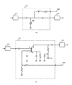
「受信部」410は、少なくとも「帯域制限器」121、「感度制御器」122、「自動利得制御増幅器」123、「選局器」126、「復調器」128からなる。 The “reception unit” 410 includes at least a “band limiter” 121, a “sensitivity controller” 122, an “automatic gain control amplifier” 123, a “channel selector” 126, and a “demodulator” 128.
「アンテナ」111で受けた「受信信号」331は「受信部」410に入力される。「復調信号」332が「受信部」410から出力される。「復調信号」332は「基地局が伝送した情報」を含んでいる。 The “reception signal” 331 received by the “antenna” 111 is input to the “reception unit” 410. A “demodulation signal” 332 is output from the “reception unit” 410. The “demodulated signal” 332 includes “information transmitted by the base station”.
「感度制御器」122は、「制御信号発生部」450からの「補正制御信号」352によって、受信感度を可変できる。 The “sensitivity controller” 122 can change the reception sensitivity by the “correction control signal” 352 from the “control signal generator” 450.
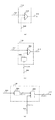
「感度制御器」122の回路例を図11に示す。
「感度制御器」122は、例えば、図11(a)に示すように構成することができる。図11(a)の例では、「感度制御器」122は、一端が「帯域制限器」121に接続された「第1コンデンサ」と、アノード端子が「第1コンデンサ」の他端に接続されカソード端子が接地された「PINダイオード」564と、一端から「補正制御信号」352を入力する「抵抗素子」と、一端が「抵抗素子」の他端に接続され他端が「PINダイオード」564のアノード端子に接続された「コイル」と、一端が「PINダイオード」564のアノード端子に接続され他端が「自動利得制御増幅器」123に接続された「第2コンデンサ」とを有して構成されている。A circuit example of the “sensitivity controller” 122 is shown in FIG.
For example, the “sensitivity controller” 122 can be configured as shown in FIG. In the example of FIG. 11A, the “sensitivity controller” 122 has one end connected to the “band limiter” 121 and the anode terminal connected to the other end of the “first capacitor”. A “PIN diode” 564 having a cathode terminal grounded, a “resistance element” for inputting a “correction control signal” 352 from one end, and one end connected to the other end of the “resistance element” and the other end “PIN diode” 564 And a “second capacitor” having one end connected to the anode terminal of “PIN diode” 564 and the other end connected to “automatic gain control amplifier” 123. Has been.
「感度制御器」122は、例えば、図11(b)に示すように構成することもできる。図11(b)の例では、「感度制御器」122は、一端が「帯域制限器」121に接続された「第1コンデンサ」と、一端が接地された「第2コンデンサ」と、一端が接地された「第1抵抗素子」と、一端から「補正制御信号」352を入力する「第2抵抗素子」と、第1ゲート端子G1が「第1コンデンサ」の他端に接続され第2ゲート端子G2が「第2コンデンサ」、「第1抵抗素子」及び「第2抵抗素子」の他端に接続された「デュアルゲート電界効果トランジスタ」と、一端が「デュアルゲート電界効果トランジスタ」のソース端子Sに接続され他端が接地された「第3コンデンサ」と、一端が「デュアルゲート電界効果トランジスタ」のソース端子Sに接続され他端が接地された「第3抵抗素子」と、一端が「デュアルゲート電界効果トランジスタ」のドレイン端子Dに接続され他端が「電源」VDDに接続された「第4抵抗素子」と、一端が「電源」VDDに接続され他端が接地された「第4コンデンサ」と、一端が「デュアルゲート電界効果トランジスタ」のドレイン端子Dに接続され他端が「自動利得制御増幅器」123に接続された「第5コンデンサ」とを有して構成されている。 The “sensitivity controller” 122 can also be configured as shown in FIG. In the example of FIG. 11B, the “sensitivity controller” 122 includes a “first capacitor” whose one end is connected to the “band limiter” 121, a “second capacitor” whose one end is grounded, and one end that is The grounded “first resistance element”, the “second resistance element” for inputting the “correction control signal” 352 from one end, and the first gate terminal G1 connected to the other end of the “first capacitor” are connected to the second gate. A “dual gate field effect transistor” in which the terminal G2 is connected to the other ends of the “second capacitor”, “first resistance element”, and “second resistance element”, and a source terminal of the “dual gate field effect transistor” at one end A “third capacitor” connected to S and the other end grounded, a “third resistor element” having one end connected to the source terminal S of the “dual gate field effect transistor” and the other end grounded, and one end “ Dual gate electric field A “fourth resistor element” connected to the drain terminal D of the “effect transistor” and connected to the “power supply” VDD at the other end; and a “fourth capacitor” connected at one end to the “power supply” VDD and connected at the other end to the ground. , Having a “fifth capacitor” having one end connected to the drain terminal D of the “dual gate field effect transistor” and the other end connected to the “automatic gain control amplifier” 123.
「送信部」470は、少なくとも「搬送波発生器」171、「変調器」172、「送信電力制御器」173からなる。 The “transmission unit” 470 includes at least a “carrier wave generator” 171, a “modulator” 172, and a “transmission power controller” 173.
「相手へ伝送したい情報」を含んだ「変調信号」374は、「送信部」470に入力される。「送信部」470は、「送信信号」375を発生させ、「アンテナ」111へ出力する。 “Modulation signal” 374 including “information to be transmitted to the other party” is input to “transmission unit” 470. “Transmission unit” 470 generates “transmission signal” 375 and outputs it to “antenna” 111.
「送信電力制御器」173は、「制御信号発生部」450からの「補正制御信号」352によって、送信電力を可変できる。 The “transmission power controller” 173 can vary the transmission power by the “correction control signal” 352 from the “control signal generator” 450.
「送信電力制御器」173の回路例を図12に示す。
「送信電力制御器」173は、図12(a)に示すように構成することができる。図12(a)の例では、「送信電力制御器」122は、一端が「変調器」172に接続された「第1コンデンサ」と、アノード端子が「第1コンデンサ」の他端に接続されカソード端子が接地された「PINダイオード」564と、一端から「補正制御信号」352を入力する「抵抗素子」と、一端が「抵抗素子」の他端に接続され他端が「PINダイオード」564のアノード端子に接続された「コイル」と、一端が「PINダイオード」564のアノード端子に接続された「第2コンデンサ」と、入力端子が「第2コンデンサ」の他端に接続され出力端子から「送信信号」375を出力する「電力増幅器」566とを有して構成されている。A circuit example of the “transmission power controller” 173 is shown in FIG.
The “transmission power controller” 173 can be configured as shown in FIG. In the example of FIG. 12A, the “transmission power controller” 122 has one end connected to the “modulator” 172 and the anode terminal connected to the other end of the “first capacitor”. A “PIN diode” 564 having a cathode terminal grounded, a “resistance element” for inputting a “correction control signal” 352 from one end, and one end connected to the other end of the “resistance element” and the other end “PIN diode” 564 The “coil” connected to the anode terminal of the first terminal, the “second capacitor” connected to the anode terminal of the “PIN diode” 564 at one end, and the output terminal connected to the other end of the “second capacitor” from the output terminal And a “power amplifier” 566 that outputs a “transmission signal” 375.
「送信電力制御器」173は、図12(b)に示すように構成することができる。図12(b)の例では、「送信電力制御器」122は、「変調器」172からの出力信号及び「補正制御信号」352を入力端子から入力し「送信信号」375を出力端子から出力する「利得可変電力増幅器」567を有して構成されている。 The “transmission power controller” 173 can be configured as shown in FIG. In the example of FIG. 12B, the “transmission power controller” 122 inputs the output signal from the “modulator” 172 and the “correction control signal” 352 from the input terminal, and outputs the “transmission signal” 375 from the output terminal. The “variable gain power amplifier” 567 is configured.
「操作手段」114は、使用者等によりなされた操作に基づいて「操作信号」315を発生させ、「制御信号発生部」450へ出力する。 The “operation means” 114 generates an “operation signal” 315 based on an operation performed by a user or the like, and outputs it to the “control signal generation unit” 450.
「操作手段」114からの「操作信号」315が「制御信号発生部」450に入力される。「制御信号発生部」450は、「操作信号」315の状態に基づいて決定した「補正制御信号」352を出力する。「制御信号発生部」450は、発生させた「補正制御信号」352を「送信部」470と「受信部」410へ共通に出力する。 The “operation signal” 315 from the “operation means” 114 is input to the “control signal generator” 450. “Control signal generator” 450 outputs “correction control signal” 352 determined based on the state of “operation signal” 315. The “control signal generator” 450 outputs the generated “correction control signal” 352 to the “transmitter” 470 and the “receiver” 410 in common.
つまり、「操作手段」114からの単一の操作によって「送信部」470と「受信部」410は制御される。 That is, the “transmission unit” 470 and the “reception unit” 410 are controlled by a single operation from the “operation unit” 114.
「制御信号発生部」450の回路例を図13に示す。
「制御信号発生部」450は、図13(a)に示すように構成することができる。図13(a)の例では、「制御信号発生部」450は、一端が「電源」VDDに接続された「第1抵抗素子」と、一端が「電源」VDDに接続された「第2抵抗素子」と、セット端子Sが「第1抵抗素子」の他端に接続されリセット端子Rが「第2抵抗素子」の他端に接続された「フリップフロップ」577と、制御端子が「フリップフロップ」577の出力端子Qに接続された「アナログスイッチ」578と、一端が「電源」VDDに接続され他端が「アナログスイッチ」578の一端に接続された「第3抵抗素子」と、一端が「アナログスイッチ」578の一端に接続され他端が接地された「第4抵抗素子」と、一端が「アナログスイッチ」578の他端に接続され他端が接地された「第5抵抗素子」と、入力端子が「アナログスイッチ」578の一端に接続され出力端子から「補正制御信号」352を出力する「ボルテージフォロワ増幅器」551とを有して構成されている。A circuit example of the “control signal generator” 450 is shown in FIG.
The “control signal generator” 450 can be configured as shown in FIG. In the example of FIG. 13A, the “control signal generator” 450 includes a “first resistance element” having one end connected to the “power supply” VDD and a “second resistance” having one end connected to the “power supply” VDD. "Flip-flop" 577 in which the set terminal S is connected to the other end of the "first resistance element" and the reset terminal R is connected to the other end of the "second resistance element", and the control terminal is "flip-flop""Analogswitch" 578 connected to output terminal Q of 577, "Third resistance element" having one end connected to "Power supply" VDD and the other end connected to one end of "Analog switch" 578, and one end A “fourth resistor element” connected to one end of the “analog switch” 578 and grounded at the other end, and a “fifth resistor element” connected at one end to the other end of the “analog switch” 578 and grounded at the other end. , Input terminal is `` analog switch And a connected output terminal to one end of the 578 "correction control signal" 352 and a "voltage follower amplifier" 551 for outputting.
「制御信号発生部」450は、図13(b)に示すように構成することができる。図13(b)の例では、「制御信号発生部」450は、一端が「電源」VDDに接続された「第1抵抗素子」と、一端が「電源」VDDに接続された「第2抵抗素子」と、セット端子Sが「第1抵抗素子」の他端に接続されリセット端子Rが「第2抵抗素子」の他端に接続された「フリップフロップ」577と、アウトプット・イネーブル端子OEが「フリップフロップ」577の出力端子Qに接続され出力端子から「補正制御信号」352を出力する第1の「スリーステートバッファー」576と、一端が第1の「スリーステートバッファー」576のn+1個の入力端子のそれぞれに接続され他端が接地されたn+1個の「第1スイッチ素子」と、一端が「電源」VDDに接続され他端が第1の「スリーステートバッファー」576のn+1個の入力端子のそれぞれに接続されたn+1個の「第3抵抗素子」と、アウトプット・イネーブル端子OEが「フリップフロップ」577の反転出力端子 ̄Qに接続され出力端子から「補正制御信号」352を出力する第2の「スリーステートバッファー」576と、一端が第2の「スリーステートバッファー」576のn+1個の入力端子のそれぞれに接続され他端が接地されたn+1個の「第2スイッチ素子」と、一端が「電源」VDDに接続され他端が第2の「スリーステートバッファー」576のn+1個の入力端子のそれぞれに接続されたn+1個の「第4抵抗素子」とを有して構成されている。 The “control signal generator” 450 can be configured as shown in FIG. In the example of FIG. 13B, the “control signal generator” 450 includes a “first resistance element” whose one end is connected to the “power supply” VDD and a “second resistor” whose one end is connected to the “power supply” VDD. Element ”, a“ flip-flop ”577 in which the set terminal S is connected to the other end of the“ first resistance element ”and the reset terminal R is connected to the other end of the“ second resistance element ”, and an output enable terminal OE Is connected to the output terminal Q of the “flip-flop” 577 and outputs a “correction control signal” 352 from the output terminal, and one end is n + 1 pieces of the first “three-state buffer” 576. N + 1 “first switch elements” connected to the respective input terminals of the first and second terminals are grounded, and n of the first “three-state buffer” 576 having one end connected to the “power supply” VDD and the other end. The n + 1 “third resistance element” connected to each of the one input terminal and the output enable terminal OE are connected to the inverting output terminal  ̄Q of the “flip-flop” 577 and the “correction control signal” is output from the output terminal. ”352 for outputting“ 352 ”and n + 1“ second state buffers ”having one end connected to each of the n + 1 input terminals of the second“ three state buffer ”576 and the other end grounded. “Switch element” and n + 1 “fourth resistance elements” having one end connected to the “power supply” VDD and the other end connected to each of the n + 1 input terminals of the second “three-state buffer” 576. Configured.
図13(a)、(b)の例では、「操作手段」114は、一端が「フリップフロップ」577のセット端子Sに接続され他端が接地された「第1スイッチ素子」と、一端が「フリップフロップ」577のリセット端子Rに接続され他端が接地された「第2スイッチ素子」とを有して構成されている。 In the example of FIGS. 13A and 13B, the “operation unit” 114 has a “first switch element” whose one end is connected to the set terminal S of the “flip-flop” 577 and the other end is grounded, and one end is The “flip-flop” 577 is connected to the reset terminal R and has the other end connected to the “second switch element”.
この無線送受信機の送信電力が「通常の送信電力」である場合の動作を以下に説明する。 The operation when the transmission power of the wireless transceiver is “normal transmission power” will be described below.
なお、この無線送受信機の送信電力が「通常の送信電力」である場合の動作は、従来の無線端末機の動作と同等である。 The operation when the transmission power of the wireless transceiver is “normal transmission power” is equivalent to the operation of the conventional wireless terminal.
この無線送受信機の送信電力が「通常の送信電力」である場合、「制御信号発生部」450は、「通常の送信電力」と「通常の受信感度」を維持する値の「補正制御信号」352を発生させ、「送信部」470と「受信部」410へ出力している。 When the transmission power of the wireless transceiver is “normal transmission power”, the “control signal generation unit” 450 sets the “correction control signal” to a value that maintains “normal transmission power” and “normal reception sensitivity”. 352 is generated and output to the “transmission unit” 470 and the “reception unit” 410.
「送信部」470の構成要素である「送信電力制御器」173には、「通常の送信電力」を維持する値の「補正制御信号」352が入力されているため、「送信部」470は、「通常の送信電力」によって「送信信号」375を出力している。 Since the “transmission power controller” 173 that is a component of the “transmission unit” 470 is input with the “correction control signal” 352 that maintains the “normal transmission power”, the “transmission unit” 470 The “transmission signal” 375 is output by “normal transmission power”.
また、「受信部」410の構成要素である「感度制御器」122には、「通常の受信感度」を維持する値の「補正制御信号」352が入力されているため、「受信部」410は、「通常の受信感度」によって「復調信号」332を発生している。 In addition, since the “sensitivity controller” 122 that is a component of the “reception unit” 410 is input with the “correction control signal” 352 that maintains the “normal reception sensitivity”, the “reception unit” 410 Generates “demodulated signal” 332 according to “normal reception sensitivity”.
送信電力を下げたときの不具合について説明する。
無線基地局から届いた電波の強度に応じて、無線送受信機は送信電力を決定している。A problem when the transmission power is lowered will be described.
The wireless transceiver determines the transmission power according to the intensity of the radio wave received from the wireless base station.
無線基地局から届いた電波が強ければ、無線送受信機は送信電力を小さくする。逆に、無線基地局から届いた電波が弱ければ、無線送受信機は送信電力を大きくする。 If the radio wave received from the radio base station is strong, the radio transceiver reduces the transmission power. Conversely, if the radio wave received from the radio base station is weak, the radio transceiver increases the transmission power.
通常、無線送受信機は、必要最低限の送信電力で送信している。
例えば、無線送受信機が無線基地局の電波を受信できているとき、単純に無線送受信機の送信電力を小さくすると、無線基地局に届かなくなり通信ができなくなる。また、無線基地局から見て無線送受信機の送信出力と受信感度の「通信の対称性」が崩れる。このため、無線基地局と基地局網は、この無線送受信機に対して正常な運用ができなくなる。Usually, the wireless transceiver transmits with the minimum necessary transmission power.
For example, when the radio transceiver is receiving radio waves from a radio base station, if the transmission power of the radio transceiver is simply reduced, it will not reach the radio base station and communication will not be possible. In addition, the “transmission symmetry” between the transmission output and the reception sensitivity of the wireless transceiver as viewed from the wireless base station is broken. For this reason, the radio base station and the base station network cannot operate normally for this radio transceiver.
このような不具合及びこれを解決する方法を従来との対比においてより具体的に説明する。 Such a problem and a method for solving it will be described more specifically in comparison with the prior art.
図21(a)〜(c)は、従来の無線端末機の送信電力特性、受信感度特性及び受信強度特性を示す図であり、図21(d)〜(f)は、送信電力の上限値のみを低下させた場合の従来の無線端末機の送信電力特性、受信感度特性及び受信強度特性を示す図である。 FIGS. 21A to 21C are diagrams illustrating transmission power characteristics, reception sensitivity characteristics, and reception strength characteristics of a conventional wireless terminal. FIGS. 21D to 21F are upper limit values of transmission power. FIG. 6 is a diagram illustrating a transmission power characteristic, a reception sensitivity characteristic, and a reception intensity characteristic of a conventional wireless terminal when only the frequency is reduced.
図22(a)〜(c)は、従来の無線端末機の送信電力特性、受信感度特性及び受信強度特性を示す図であり、図22(d)〜(f)は、本実施の形態に係る無線送受信機の送信電力特性、受信感度特性及び受信強度特性を示す図である。 22A to 22C are diagrams showing transmission power characteristics, reception sensitivity characteristics, and reception strength characteristics of a conventional wireless terminal, and FIGS. 22D to 22F are illustrated in this embodiment. It is a figure which shows the transmission power characteristic of the radio | wireless transmitter / receiver which concerns, a receiving sensitivity characteristic, and a receiving intensity characteristic.
図21(a)、(d)及び図22(a)、(d)の縦軸800は送信電力を示し、図21(b)、(e)及び図22(b)、(e)の縦軸801は受信感度を示し、図21(c)、(f)及び図21(c)、(f)の縦軸802は受信強度を示している。また、図21及び図22の各グラフの横軸803は、従来の無線端末機(又は本実施の形態に係る無線送受信機)と無線基地局との間の伝搬損失(≒距離)を示している。 The vertical axis 800 in FIGS. 21A, 21D, 22A, and 22D represents transmission power, and the vertical axes in FIGS. 21B, 21E, 22B, and 22E. An axis 801 represents reception sensitivity, and a vertical axis 802 in FIGS. 21C and 21F and FIGS. 21C and 21F represents reception intensity. Also, the horizontal axis 803 of each graph in FIGS. 21 and 22 indicates the propagation loss (≈distance) between the conventional wireless terminal (or the wireless transceiver according to this embodiment) and the wireless base station. Yes.
従来の無線端末機では、図21(a)に示すように、無線基地局との間の伝搬損失が高くなるにつれて(すなわち、無線基地局から届いた電波が弱くなるにつれて)送信電力が増加するように送信電力が制御されている。送信電力は、無線端末機が発揮できる最大送信電力804に達すると最大送信電力804のまま一定となり、伝搬損失が最大送信電力804に達した点よりも若干高くなった点で無線基地局に信号を伝達することができなくなる。一方、受信感度は、図21(b)に示すように、伝搬損失にかかわらず、無線端末機が発揮できる最大受信感度805に設定されているので、受信強度は、図21(c)に示すように、伝搬損失が高くなるにつれて最大受信強度815から減少し、許容値806まで低下すると無線基地局からの信号を受信することができなくなる。 In the conventional wireless terminal, as shown in FIG. 21A, the transmission power increases as the propagation loss with the wireless base station increases (that is, as the radio wave received from the wireless base station becomes weaker). Thus, the transmission power is controlled. When the transmission power reaches the maximum transmission power 804 that can be exhibited by the wireless terminal, the maximum transmission power 804 remains constant, and a signal is transmitted to the radio base station at a point where the propagation loss is slightly higher than the point at which the maximum transmission power 804 is reached. Can no longer communicate. On the other hand, as shown in FIG. 21B, the reception sensitivity is set to the maximum reception sensitivity 805 that can be exhibited by the wireless terminal regardless of the propagation loss. Therefore, the reception intensity is shown in FIG. Thus, as the propagation loss increases, the maximum reception strength 815 decreases, and when the propagation loss decreases to an allowable value 806, it becomes impossible to receive a signal from the radio base station.
このような状態では、無線端末機が無線基地局に信号を伝達できる範囲807と、無線端末機が無線基地局から信号を受信できる範囲808とが一致しているので、「通信の対称性」が保たれている。これは、アンテナの特性や受信部の雑音指数などを加味して「通信の対称性」が保たれるようにシステム設計がなされているからである。そのため、伝搬損失が範囲807、808を超えて範囲809、810まで高くなると、無線端末機では、無線基地局と通信が確立できなくなるので「圏外」が表示される。 In such a state, the range 807 in which the wireless terminal can transmit a signal to the wireless base station and the range 808 in which the wireless terminal can receive a signal from the wireless base station are the same. Is maintained. This is because the system is designed so that “communication symmetry” is maintained in consideration of the characteristics of the antenna and the noise figure of the receiver. Therefore, when the propagation loss exceeds the ranges 807 and 808 and increases to the ranges 809 and 810, the wireless terminal cannot display communication with the wireless base station, so “out of range” is displayed.
これに対し、送信電力の上限値のみを一定値811まで低下させた場合、送信電力は、図21(d)に示すように、一定値811に達すると一定値811のまま一定となり、伝搬損失が一定値811に達した点よりも若干高くなった点で無線基地局に信号を伝達することができなくなる。したがって、無線端末機が無線基地局に信号を伝達できる範囲812は、送信電力の上限値を低下させない場合に比して小さくなる。一方、受信感度は、図21(e)に示すように、伝搬損失にかかわらず最大受信感度805に設定されているので、受信強度は、図21(f)に示すように、伝搬損失が高くなるにつれて最大受信強度815から減少し、許容値806まで低下すると無線基地局からの信号を受信することができなくなる。したがって、無線端末機が無線基地局から信号を受信できる範囲808は、送信電力の上限値を低下させない場合と同一となる。 On the other hand, when only the upper limit value of the transmission power is reduced to the constant value 811, the transmission power becomes constant at the constant value 811 when reaching the constant value 811 as shown in FIG. The signal cannot be transmitted to the radio base station at a point slightly higher than the point at which the value reaches a certain value 811. Therefore, the range 812 in which the radio terminal can transmit a signal to the radio base station is smaller than when the upper limit value of the transmission power is not lowered. On the other hand, the reception sensitivity is set to the maximum reception sensitivity 805 regardless of the propagation loss as shown in FIG. 21 (e), so the reception intensity is high in the propagation loss as shown in FIG. 21 (f). As it decreases, the maximum reception strength 815 decreases, and when it decreases to an allowable value 806, a signal from the radio base station cannot be received. Accordingly, the range 808 in which the wireless terminal can receive a signal from the wireless base station is the same as when the upper limit value of the transmission power is not reduced.
このような状態では、無線端末機が無線基地局に信号を伝達できる範囲812と、無線端末機が無線基地局から信号を受信できる範囲808とが一致していないので、「通信の対称性」が崩れる。すなわち、伝搬損失が範囲812を超えるが範囲808を超えない範囲にある場合は、無線基地局に信号を伝達することができないが無線基地局から信号を受信することができる一方向の通信状態となるので、無線端末機では、「圏外」が表示されていないにもかかわらず、無線基地局に発信ができないという状態となる。これでは、使用者に混乱を与えるだけでなく、上記のとおり、無線基地局と基地局網は、無線端末機に対して正常な運用ができなくなる。 In such a state, the range 812 in which the wireless terminal can transmit signals to the wireless base station does not match the range 808 in which the wireless terminal can receive signals from the wireless base station. Collapses. That is, when the propagation loss exceeds the range 812 but does not exceed the range 808, a one-way communication state in which a signal cannot be transmitted to the radio base station but a signal can be received from the radio base station Therefore, the wireless terminal is in a state where it cannot make a call to the wireless base station even though “out of service area” is not displayed. This not only confuses the user, but also prevents the radio base station and the base station network from operating normally with respect to the radio terminal as described above.
そこで、本実施の形態に係る無線送受信機では、図22(d)に示すように、「操作手段」114の操作によって送信電力の上限値を一定値811まで低下させた場合、図22(e)に示すように、低下した送信電力の上限値811に応じて受信感度を一定値813まで低下させる。例えば、送信電力の上限値を最大送信電力804(例えば、1[W])から一定値811(例えば、0.1[W])まで低下させた場合、受信感度を最大受信感度805(例えば、0[dB])から一定値813(例えば、−10[dB])まで低下させる。受信感度が低下すれば、受信強度も、図22(f)に示すように、伝搬損失が高くなるにつれて最大受信強度815よりも所定値(最大受信感度805と一定値813との差分に相当)低下した一定値816から減少し、許容値806まで低下すると無線基地局からの信号を受信することができなくなる。したがって、受信強度の範囲が小さくなるので、無線送受信機が無線基地局から信号を受信できる範囲814は、受信感度を低下させない場合に比して小さくなる。 Therefore, in the radio transceiver according to the present embodiment, as shown in FIG. 22D, when the upper limit value of the transmission power is reduced to a constant value 811 by the operation of the “operation means” 114, FIG. ), The reception sensitivity is reduced to a constant value 813 in accordance with the reduced upper limit value 811 of the transmission power. For example, when the upper limit value of the transmission power is reduced from the maximum transmission power 804 (for example, 1 [W]) to a constant value 811 (for example, 0.1 [W]), the reception sensitivity is increased to the maximum reception sensitivity 805 (for example, 0 [dB]) to a certain value 813 (for example, −10 [dB]). When the reception sensitivity decreases, the reception intensity also becomes a predetermined value (corresponding to a difference between the maximum reception sensitivity 805 and a constant value 813) as the propagation loss increases as the propagation loss increases, as shown in FIG. When it decreases from the lowered fixed value 816 and falls to the allowable value 806, it becomes impossible to receive a signal from the radio base station. Accordingly, since the range of the reception intensity is reduced, the range 814 in which the radio transceiver can receive a signal from the radio base station is smaller than when the reception sensitivity is not lowered.
これにより、無線送受信機が無線基地局に信号を伝達できる範囲812と、無線送受信機が無線基地局から信号を受信できる範囲814とが一致するので、「通信の対称性」が保たれる。 As a result, the range 812 in which the radio transceiver can transmit signals to the radio base station coincides with the range 814 in which the radio transceiver can receive signals from the radio base station, so that “symmetry of communication” is maintained.
なお、受信感度は、送信電力の上限値に応じて低下させればよいが、この場合、無線送受信機が無線基地局から信号を受信できる範囲(受信範囲)が、無線送受信機が無線基地局に信号を伝達できる範囲(伝達範囲)と一致するように低下させることが好ましい。ただし、受信範囲及び伝達範囲が必ずしも一致しなくてもよく、受信感度をまったく低下させない場合に比して、受信範囲と伝達範囲との不一致部分を小さくさえできれば、「通信の対称性」が崩れる度合いを小さくすることができるので、送信電力の上限値を低下させた場合は、受信範囲が伝達範囲と一致するか又はその不一致部分が小さくなるように受信感度を低下させればよいということができる。 The reception sensitivity may be reduced according to the upper limit value of the transmission power. In this case, the range in which the radio transceiver can receive signals from the radio base station (reception range) is It is preferable to lower the signal so as to coincide with a range (transmission range) in which a signal can be transmitted. However, the reception range and the transmission range do not necessarily need to be the same, and if the mismatch between the reception range and the transmission range can be reduced as compared with the case where the reception sensitivity is not lowered at all, the “symmetry of communication” is lost. Since the degree can be reduced, when the upper limit value of the transmission power is reduced, it is only necessary to reduce the reception sensitivity so that the reception range matches the transmission range or the mismatched portion becomes small. it can.
次に、本実施の形態に係る無線送受信機について、送信電力を「通常より低い送信電力」へ変更したときの動作、及び、前記不具合を防ぐ動作を「感度制御器」122に可変減衰器(Variable Attenuator)を用いた例で下記に説明する。 Next, regarding the wireless transceiver according to the present embodiment, the operation when the transmission power is changed to “transmission power lower than normal” and the operation for preventing the above-described problem are referred to as a “sensitivity controller” 122 in a variable attenuator ( An example using a variable attenuator) will be described below.
ここで、通常の動作として、所定の範囲内で増減している送信電力を使用者が手動で1/10に変更しようとする。 Here, as a normal operation, the user tries to manually change the transmission power increasing or decreasing within a predetermined range to 1/10.
使用者が「操作手段」114を操作すると、「制御信号発生部」450から「補正制御信号」352が、「感度制御器」122(可変減衰器)と「送信電力制御器」173に入力される。 When the user operates “operation means” 114, “correction control signal” 352 is input from “control signal generator” 450 to “sensitivity controller” 122 (variable attenuator) and “transmission power controller” 173. The
ここで、「補正制御信号」352は、1/10にするという値である。
「送信電力制御器」173は、送信電力を本来の最大送信電力の1/10に設定する。Here, the “correction control signal” 352 has a value of 1/10.
The “transmission power controller” 173 sets the transmission power to 1/10 of the original maximum transmission power.
「感度制御器」122(可変減衰器)は、減衰率を1/10に設定する。
したがって、本実施の形態に係る無線送受信機は、使用者が行った操作によって、送信電力を「通常より低い送信電力」へ切り替えたり、「通常の送信電力」へ戻したりが可能であり、また、その送信電力の切り替えに連動して、受信感度も「通常より低い受信感度」へ切り替わったり、「通常の受信感度」へ戻ったりする。“Sensitivity controller” 122 (variable attenuator) sets the attenuation rate to 1/10.
Therefore, the radio transceiver according to the present embodiment can switch the transmission power to “transmission power lower than normal” or return to “normal transmission power” by the operation performed by the user. In conjunction with the switching of the transmission power, the reception sensitivity is switched to “reception sensitivity lower than normal” or returned to “normal reception sensitivity”.
以下、「受信部」410の受信感度を下げる方法について述べる。
「受信部」410の構成要素である「感度制御器」122は、可変減衰器、可変増幅器によって実施可能である。Hereinafter, a method for reducing the reception sensitivity of the “reception unit” 410 will be described.
The “sensitivity controller” 122 that is a component of the “receiving unit” 410 can be implemented by a variable attenuator and a variable amplifier.
また、これらを使用する他に、「受信部」410の受信感度を下げるには、「自動利得制御増幅器」123の利得可変範囲を狭めることで可能である。 In addition to using these, the reception sensitivity of the “reception unit” 410 can be lowered by narrowing the variable gain range of the “automatic gain control amplifier” 123.
このようにして、本実施の形態では、無線送受信機は、「操作手段」114の操作によって送信電力の上限値を低下させ、低下した送信電力の上限値に応じて受信感度を低下させる。 Thus, in the present embodiment, the radio transceiver reduces the upper limit value of transmission power by operating the “operation means” 114, and lowers the reception sensitivity according to the lower limit value of transmission power.
これにより、使用者が無線送受信機の送信電力の上限値を決定することができ、使用者が送信電力を管理することで消費電力が抑えられ、連続稼動時間を延ばすことが可能になる。また、無線周波電磁界の人体への影響を弱くすることができる。さらに、「通信の対称性」が崩れる度合いを小さくすることができる。 As a result, the user can determine the upper limit value of the transmission power of the wireless transceiver, and the user can control the transmission power, thereby reducing the power consumption and extending the continuous operation time. Further, the influence of the radio frequency electromagnetic field on the human body can be weakened. Furthermore, the degree of “communication symmetry” breaking can be reduced.
〔第2の実施の形態〕
本発明の第2の実施の形態に係る無線送受信機について述べる。図2は、第2の実施の形態に係る無線送受信機の基本構成を示す図である。[Second Embodiment]
A radio transceiver according to the second embodiment of the present invention will be described. FIG. 2 is a diagram illustrating a basic configuration of a radio transceiver according to the second embodiment.
この無線送受信機の構成、及び、各部の動作について説明する。
この無線送受信機は、「アンテナ」111、「受信部」420、「通信成立の判断部」430、「送信電力決定部」460、「送信部」470、「制御信号発生部」450、「操作手段」114から構成される。The configuration of this wireless transceiver and the operation of each unit will be described.
This wireless transceiver includes an “antenna” 111, a “reception unit” 420, a “communication establishment determination unit” 430, a “transmission power determination unit” 460, a “transmission unit” 470, a “control signal generation unit” 450, an “operation” Means "114.
「受信部」420は、少なくとも「帯域制限器」121、「自動利得制御増幅器A」124、「自動利得制御増幅器B」125、「選局器」126、「復調器」128、「受信レベル発生器」129からなる。 “Receiver” 420 includes at least “band limiter” 121, “automatic gain control amplifier A” 124, “automatic gain control amplifier B” 125, “channel selector” 126, “demodulator” 128, “reception level generation” Instrument "129.
「アンテナ」111で受けた「受信信号」331は、「受信部」420に入力される。「復調信号」332が「受信部」420から出力される。「復調信号」332は「基地局が伝送した情報」を含んでいる。 The “reception signal” 331 received by the “antenna” 111 is input to the “reception unit” 420. A “demodulated signal” 332 is output from the “receiving unit” 420. The “demodulated signal” 332 includes “information transmitted by the base station”.
「受信レベル発生器」129は、「受信部」420に入力された「受信信号」331の強度や品質を「受信レベル信号」335に変換して出力する。「受信レベル発生器」129は、「受信レベル信号」335を「通信成立の判断部」430と「送信電力決定部」460へ同時に出力する。 The “reception level generator” 129 converts the intensity and quality of the “reception signal” 331 input to the “reception unit” 420 into a “reception level signal” 335 and outputs it. The “reception level generator” 129 outputs the “reception level signal” 335 to the “communication establishment determination unit” 430 and the “transmission power determination unit” 460 simultaneously.
なお、「自動利得制御増幅器A」124と「自動利得制御増幅器B」125については、両者が必須ということではなく、少なくとも一つの「自動利得制御増幅器」があれば実施可能である。 Note that “automatic gain control amplifier A” 124 and “automatic gain control amplifier B” 125 are not essential, and can be implemented if there is at least one “automatic gain control amplifier”.
「通信成立の判断部」430は、少なくとも「レベル比較器」141からなる。
「受信部」420からの「受信レベル信号」335と、「制御信号発生部」450からの「補正制御信号」352が、「通信成立の判断部」430に入力される。The “communication establishment determination unit” 430 includes at least a “level comparator” 141.
The “reception level signal” 335 from the “reception unit” 420 and the “correction control signal” 352 from the “control signal generation unit” 450 are input to the “communication establishment determination unit” 430.
「通信成立の判断部」430は、「受信レベル信号」335の値と「補正制御信号」352の値とを比較し、「通信成立の判断信号」343の状態を決定する。 The “communication establishment determination unit” 430 compares the value of the “reception level signal” 335 and the value of the “correction control signal” 352 to determine the state of the “communication establishment determination signal” 343.
「通信成立の判断信号」343は、「通信成立が可」又は「通信成立が否」のどちらかの状態で出力される。 The “communication establishment determination signal” 343 is output in a state of “communication establishment is possible” or “communication establishment is not possible”.
「通信成立の判断部」430の回路例を図15に示す。
「通信成立の判断部」430は、図15(a)に示すように構成することができる。図15(a)の例では、「通信成立の判断部」430は、「レベル比較器」141を有して構成されている。「レベル比較器」141は、アナログ回路による「比較器」553を有して構成されている。「比較器」553は、「受信レベル信号」335を非反転入力端子から入力し、「補正制御信号」352を反転入力端子から入力し、「通信成立の判断信号」343を出力端子から出力する。A circuit example of the “communication establishment determination unit” 430 is shown in FIG.
The “communication establishment determination unit” 430 can be configured as shown in FIG. In the example of FIG. 15A, the “communication establishment determination unit” 430 includes a “level comparator” 141. The “level comparator” 141 includes a “comparator” 553 that is an analog circuit. “Comparator” 553 inputs “reception level signal” 335 from the non-inverting input terminal, inputs “correction control signal” 352 from the inverting input terminal, and outputs “communication establishment judgment signal” 343 from the output terminal. .
「通信成立の判断部」430は、図15(b)に示すように構成することができる。図15(b)の例では、「通信成立の判断部」430は、「レベル比較器」141を有して構成されている。「レベル比較器」141は、「受信レベル信号」335を入力しA/D変換する「A/Dコンバーター」568と、ロジック回路による重み付き「比較器」558とを有して構成されている。「比較器」558は、A/D変換された「受信レベル信号」335を第1入力端子から入力し、「補正制御信号」352(デジタル信号)を第2入力端子から入力し、「通信成立の判断信号」343を出力端子から出力する。
The “communication establishment determination unit” 430 can be configured as shown in FIG. In the example of FIG. 15B, the “communication establishment determination unit” 430 includes a “level comparator” 141. The “level comparator” 141 is configured to include an “A / D converter” 568 that inputs a “reception level signal” 335 and performs A / D conversion, and a weighted “comparator” 558 by a logic circuit. . The “comparator” 558 inputs the A / D converted “reception level signal” 335 from the first input terminal, and inputs the “correction control signal” 352 (digital signal) from the second input terminal. The
「送信電力決定部」460は、少なくとも「レベル演算器」163、「レベル制限器」161からなる。 The “transmission power determination unit” 460 includes at least a “level calculator” 163 and a “level limiter” 161.
「受信部」420からの「受信レベル信号」335と、「制御信号発生部」450からの「補正制御信号」352が、「送信電力決定部」460に入力される。 The “reception level signal” 335 from the “reception unit” 420 and the “correction control signal” 352 from the “control signal generation unit” 450 are input to the “transmission power determination unit” 460.
「送信電力決定部」460の「レベル演算器」163が、「受信レベル信号」335の値から送信電力を決定する。 The “level calculator” 163 of the “transmission power determination unit” 460 determines the transmission power from the value of the “reception level signal” 335.
「レベル制限器」161は、「レベル演算器」163が決定した送信電力が、「補正制御信号」352の値に基づいた上限値を越えていないか確認し、もし越えているときは、送信電力を上限値に変更する。これを「送信電力制御信号」362として「送信部」470へ出力する。 The “level limiter” 161 checks whether or not the transmission power determined by the “level calculator” 163 exceeds the upper limit value based on the value of the “correction control signal” 352. Change the power to the upper limit. This is output as “transmission power control signal” 362 to “transmission unit” 470.
すなわち、「補正制御信号」352の値に応じて上限値制限を加えているので、上限値制限された「送信電力制御信号」362が出力され、送信電力は所望の値以下に抑制される。 That is, since the upper limit value is limited according to the value of the “correction control signal” 352, the “transmission power control signal” 362 with the upper limit value is output, and the transmission power is suppressed to a desired value or less.
「送信電力決定部」460の回路例を図16及び図17に示す。
「送信電力決定部」460は、図16(a)に示すように構成することができる。図16(a)の例では、「送信電力決定部」460は、「レベル制限器」161及び「レベル演算器」163を有して構成されている。「レベル演算器」163は、アナログ回路による「反転増幅器」533を有して構成されている。「反転増幅器」533は、「受信レベル信号」335を入力し、これを増幅して出力する。「レベル制限器」161は、アナログ回路による「レベル制限器」559を有して構成されている。「レベル制限器」559は、増幅された「受信レベル信号」335を入力端子から入力し、「補正制御信号」352を「レベル制限基準電圧」717として入力し、「送信電力制限信号」362を出力端子から出力する。A circuit example of the “transmission power determination unit” 460 is shown in FIGS.
The “transmission power determination unit” 460 can be configured as shown in FIG. In the example of FIG. 16A, the “transmission power determining unit” 460 includes a “level limiter” 161 and a “level calculator” 163. The “level calculator” 163 includes an “inverting amplifier” 533 that is an analog circuit. The “inverting amplifier” 533 receives the “reception level signal” 335, amplifies it, and outputs it. The “level limiter” 161 includes a “level limiter” 559 based on an analog circuit. The “level limiter” 559 inputs the amplified “reception level signal” 335 from the input terminal, inputs the “correction control signal” 352 as the “level limit reference voltage” 717, and outputs the “transmission power limit signal” 362. Output from the output terminal.
「送信電力決定部」460は、図16(b)に示すように構成することができる。図16(b)の例では、「送信電力決定部」460は、「レベル制限器」161及び「レベル演算器」163を有して構成されている。「レベル演算器」163は、アナログ回路による「反転増幅器」533を有して構成されている。「反転増幅器」533は、「受信レベル信号」335を入力し、これを増幅して出力する。「レベル制限器」161は、「補正制御信号」352(デジタル信号)を入力しD/A変換する「D/Aコンバーター」569と、アナログ回路による「レベル制限器」559とを有して構成されている。「レベル制限器」559は、増幅された「受信レベル信号」335を入力端子から入力し、D/A変換された「補正制御信号」352を「レベル制限基準電圧」717として入力し、「送信電力制限信号」362を出力端子から出力する。 The “transmission power determination unit” 460 can be configured as shown in FIG. In the example of FIG. 16B, the “transmission power determination unit” 460 includes a “level limiter” 161 and a “level calculator” 163. The “level calculator” 163 includes an “inverting amplifier” 533 that is an analog circuit. The “inverting amplifier” 533 receives the “reception level signal” 335, amplifies it, and outputs it. The “level limiter” 161 includes a “D / A converter” 569 that inputs a “correction control signal” 352 (digital signal) and performs D / A conversion, and a “level limiter” 559 using an analog circuit. Has been. The “level limiter” 559 inputs the amplified “reception level signal” 335 from the input terminal, inputs the D / A converted “correction control signal” 352 as the “level limit reference voltage” 717, and “transmits” “Power limit signal” 362 is output from the output terminal.
「送信電力決定部」460は、図17(a)に示すように構成することができる。図17(a)の例では、「送信電力決定部」460は、アナログ回路による「減算器」555を有して構成されている。「減算器」555は、「受信レベル信号」335及び「補正制御信号」352を入力し、「受信レベル信号」335から「補正制御信号」352を減算し、その減算結果である「送信電力制御信号」362を出力端子から出力する。 The “transmission power determination unit” 460 can be configured as shown in FIG. In the example of FIG. 17A, the “transmission power determination unit” 460 is configured to include a “subtractor” 555 using an analog circuit. The “subtractor” 555 receives the “reception level signal” 335 and the “correction control signal” 352, subtracts the “correction control signal” 352 from the “reception level signal” 335, and obtains the “transmission power control” as the subtraction result. A signal “362” is output from the output terminal.
「送信電力決定部」460は、図17(b)に示すように構成することができる。図17(b)の例では、「送信電力決定部」460は、「補正制御信号」352(デジタル信号)を入力しD/A変換する「D/Aコンバーター」569と、アナログ回路による「減算器」555を有して構成されている。「減算器」555は、「受信レベル信号」335及びD/A変換された「補正制御信号」352を入力し、「受信レベル信号」335から「補正制御信号」352を減算し、その減算結果である「送信電力制御信号」362を出力端子から出力する。 The “transmission power determination unit” 460 can be configured as shown in FIG. In the example of FIG. 17B, the “transmission power determination unit” 460 receives the “correction control signal” 352 (digital signal) and performs “D / A conversion” 569 for D / A conversion, and “subtraction” by an analog circuit. Device "555. The “subtractor” 555 receives the “reception level signal” 335 and the D / A converted “correction control signal” 352, subtracts the “correction control signal” 352 from the “reception level signal” 335, and the subtraction result The “transmission power control signal” 362 is output from the output terminal.
「送信電力決定部」460は、図17(c)に示すように構成することができる。図17(c)の例では、「送信電力決定部」460は、「受信レベル信号」335を入力しA/D変換する「A/Dコンバーター」568と、ロジック回路による「減算器」557と、「減算器」557からの出力信号をD/A変換し「送信電力制御信号」362を出力する「D/Aコンバーター」569とを有して構成されている。「減算器」557は、A/D変換された「受信レベル信号」335及び「補正制御信号」352(デジタル信号)を入力し、「受信レベル信号」335から「補正制御信号」352を減算し、その減算結果を出力端子から出力する。 The “transmission power determination unit” 460 can be configured as shown in FIG. In the example of FIG. 17C, the “transmission power determination unit” 460 inputs an “reception level signal” 335 and performs A / D conversion, an “A / D converter” 568, and a “subtractor” 557 based on a logic circuit. , “D / A converter” 569 which D / A converts the output signal from “Subtractor” 557 and outputs “Transmission power control signal” 362. The “subtractor” 557 receives the A / D converted “reception level signal” 335 and “correction control signal” 352 (digital signal), and subtracts the “correction control signal” 352 from the “reception level signal” 335. The subtraction result is output from the output terminal.
「送信部」470は、少なくとも「搬送波発生器」171、「変調器」172、「送信電力制御器」173からなる。 The “transmission unit” 470 includes at least a “carrier wave generator” 171, a “modulator” 172, and a “transmission power controller” 173.
「相手へ届けたい情報」を含んだ「変調信号」374は、「送信部」470に入力される。「送信部」470は、「送信信号」375を発生させ、「アンテナ」111へ出力する。 “Modulated signal” 374 including “information to be delivered to the other party” is input to “transmitting section” 470. “Transmission unit” 470 generates “transmission signal” 375 and outputs it to “antenna” 111.
「送信電力制御器」173は、「送信電力決定部」460からの「送信電力制御信号」362によって、送信電力を可変できる。「送信電力制御器」173の回路例は、図12に示すとおりである。 “Transmission power controller” 173 can vary the transmission power by “transmission power control signal” 362 from “transmission power determination unit” 460. A circuit example of the “transmission power controller” 173 is as shown in FIG.
「操作手段」114は、なされた操作に基づいて「操作信号」315を発生させ、「制御信号発生部」450へ出力する。 The “operation means” 114 generates an “operation signal” 315 based on the performed operation and outputs it to the “control signal generator” 450.
「操作手段」114からの「操作信号」315が「制御信号発生部」450に入力される。「制御信号発生部」450は、「操作信号」315の状態に基づいて、発生させる「補正制御信号」352の値を決定する。「制御信号発生部」450は、発生させた「補正制御信号」352を「送信電力決定部」460と「通信成立の判断部」430に出力する。「制御信号発生部」450の回路例は、図13に示すとおりである。 The “operation signal” 315 from the “operation means” 114 is input to the “control signal generator” 450. The “control signal generator” 450 determines the value of the “correction control signal” 352 to be generated based on the state of the “operation signal” 315. The “control signal generation unit” 450 outputs the generated “correction control signal” 352 to the “transmission power determination unit” 460 and the “communication establishment determination unit” 430. A circuit example of the “control signal generator” 450 is as shown in FIG.
以下、「受信レベル発生器」129の役割について説明する。
「受信レベル発生器」129は、「受信部」420を構成する「自動利得制御増幅器A」124、「自動利得制御増幅器B」125、「復調器」128などから、信号強度や信号誤り率等の情報を得て、これらを評価した結果によって「受信レベル信号」335を発生させるものである。Hereinafter, the role of the “reception level generator” 129 will be described.
“Reception level generator” 129 includes “automatic gain control amplifier A” 124, “automatic gain control amplifier B” 125, “demodulator” 128, etc. that constitute “reception unit” 420. The “reception level signal” 335 is generated based on the result of evaluating the above information and evaluating the information.
信号強度や信号誤り率等の情報は単一で使用しても良い。また複数の情報を使用しても良い。その場合は、複数の情報を並列に入力するか、又は加算して入力しても良い。 Information such as signal strength and signal error rate may be used alone. A plurality of information may be used. In that case, a plurality of pieces of information may be input in parallel or added together.
以下、「通信成立の判断部」430の役割について説明する。
無線基地局が送出した電波を無線送受信機が受信し、その受信した信号強度に対応した「受信レベル信号」335が出力される。「通信成立の判断部」430は、「補正制御信号」352によって制限された送信出力の電波が、「受信レベル信号」335の値から判断して、無線基地局に到達し通信が成立しうるかどうかの判断を行う。Hereinafter, the role of “communication establishment determination unit” 430 will be described.
The radio transmitter / receiver receives the radio wave transmitted by the radio base station, and a “reception level signal” 335 corresponding to the received signal strength is output. The “communication establishment determination unit” 430 determines whether the radio wave of the transmission output limited by the “correction control signal” 352 reaches the wireless base station by determining from the value of the “reception level signal” 335 and can establish communication. Make a judgment.
したがって、「通信成立の判断信号」343の状態が「通信成立が否」である場合は、無線送受信機の送信した電波が無線基地局で受信されない恐れがあるので、仮に無線基地局からの通信開始要求があっても、無線送受信機は通信開始をしないようにすることができる。 Therefore, when the state of the “communication establishment determination signal” 343 is “communication establishment failure”, there is a possibility that the radio base station may not receive the radio wave transmitted by the wireless transceiver. Even if there is a start request, the wireless transceiver can be configured not to start communication.
なお、このように「受信レベル信号」335により通信成立の判断をして、あらかじめ登録した電波強度より弱い受信信号の無線基地局とは通信しないように制限することは、受信感度を低下させて受信信号レベルの弱い無線基地局と通信しないことと同一である。 It should be noted that determining that communication is established by the “reception level signal” 335 and restricting communication with a radio base station having a reception signal weaker than a pre-registered radio wave intensity does not reduce reception sensitivity. This is the same as not communicating with a radio base station having a weak received signal level.
この無線送受信機の送信電力が「通常の送信電力」である場合の動作を以下に説明する。 The operation when the transmission power of the wireless transceiver is “normal transmission power” will be described below.
なお、この無線送受信機の送信電力が「通常の送信電力」である場合の動作は、従来の無線端末機の動作と同等である。 The operation when the transmission power of the wireless transceiver is “normal transmission power” is equivalent to the operation of the conventional wireless terminal.
この無線送受信機の送信電力が「通常の送信電力」である場合、「制御信号発生部」450は、「通常の送信電力」と「通常の受信感度」を維持する値の「補正制御信号」352を発生させ、「送信電力決定部」460と「通信成立の判断部」430へ出力している。 When the transmission power of the wireless transceiver is “normal transmission power”, the “control signal generation unit” 450 sets the “correction control signal” to a value that maintains “normal transmission power” and “normal reception sensitivity”. 352 is generated and output to the “transmission power determination unit” 460 and the “communication establishment determination unit” 430.
「送信電力決定部」460は、「受信レベル信号」335の値によって、「送信部」470へ出力する「送信電力制御信号」362の値を決定している。 “Transmission power determination unit” 460 determines the value of “transmission power control signal” 362 to be output to “transmission unit” 470 based on the value of “reception level signal” 335.
すなわち、「受信レベル信号」335の値が高くなると、無線基地局が近距離に存在していると判断して送信電力を抑えようと、「送信電力制御信号」362の値を低くする。逆に、「受信レベル信号」335の値が低くなると、無線基地局が遠距離に存在していると判断して、「送信電力制御信号」362の値を高くする。 That is, when the value of the “reception level signal” 335 increases, the value of the “transmission power control signal” 362 is decreased to determine that the radio base station exists at a short distance and suppress transmission power. Conversely, when the value of “reception level signal” 335 decreases, it is determined that the radio base station exists at a long distance, and the value of “transmission power control signal” 362 is increased.
このとき、「送信電力決定部」460へ入力されている「補正制御信号」352は、「通常の送信電力」を維持する値である。この値は「最大送信電力」の値であるから、「送信電力決定部」460が「送信部」470へ出力する「送信電力制御信号」362の値は、「最大送信電力」の値まで制御できる。 At this time, the “correction control signal” 352 input to the “transmission power determination unit” 460 is a value that maintains “normal transmission power”. Since this value is the value of “maximum transmission power”, the value of “transmission power control signal” 362 output from “transmission power determination unit” 460 to “transmission unit” 470 is controlled to the value of “maximum transmission power”. it can.
また、このとき、「通信成立の判断部」430へ入力されている「補正制御信号」352は、「通常の受信感度」を維持する値であるから、「通信成立の判断部」430は、その時点の「復調信号」332が、この無線送受信機が「最大送信電力」で電波を放射したときに到達可能である無線基地局からのものであるかを判断し、「通信成立の判断信号」343の状態を「通信成立が可」又は「通信成立が否」のどちらかで出力する。これは、従来の無線端末機と同等の動作である。 At this time, since the “correction control signal” 352 input to the “communication establishment determination unit” 430 is a value that maintains “normal reception sensitivity”, the “communication establishment determination unit” 430 It is determined whether the “demodulation signal” 332 at that time is from a radio base station that can be reached when this radio transceiver emits radio waves with “maximum transmission power”. "343" is output as either "communication establishment is possible" or "communication establishment is impossible". This is the same operation as a conventional wireless terminal.
さて、この状態において、従来の無線端末機は、使用者が送信電力を「通常より低い送信電力」へ変更することができず、使用者が状況に応じて送信電力を小さくすることで消費電力を抑えることが不可能であった。 In this state, the conventional wireless terminal cannot change the transmission power to “transmission power lower than normal” by the user, and the user can reduce the power consumption by reducing the transmission power according to the situation. It was impossible to suppress.
さらには、何らかの方法で単純に送信電力だけを低く変更すると、「無線基地局から届く電波はそれまでと変わらない強度で届くにもかかわらず、この無線送受信機から放射される電波は弱くなり、無線基地局へは到達できない不具合」が予想される。 Furthermore, if the transmission power is simply changed to a low value in some way, “the radio wave radiated from this radio transceiver will be weaker, even though the radio wave arrives from the radio base station with the same strength as before, "Problems that cannot reach the radio base station" are expected.
ここで、本実施の形態に係る無線送受信機について、送信電力を「通常より低い送信電力」へ変更したときの動作、及び、前記不具合を防ぐ動作を下記に説明する。 Here, regarding the radio transceiver according to the present embodiment, an operation when the transmission power is changed to “transmission power lower than normal” and an operation for preventing the above problem will be described below.
例えば、使用者が無線送受信機の送信電力を通常より低くする操作をすると、「制御信号発生部」450は、「通常より低い送信電力」と「通常より低い受信感度」が設定される値の「補正制御信号」352を「送信電力決定部」460と「通信成立の判断部」430へ共通に出力する。 For example, when the user performs an operation to lower the transmission power of the wireless transceiver, the “control signal generator” 450 is set to a value in which “transmission power lower than normal” and “reception sensitivity lower than normal” are set. “Correction control signal” 352 is output in common to “transmission power determination unit” 460 and “communication establishment determination unit” 430.
つまり、「送信電力決定部」460と「通信成立の判断部」430は、単一の操作によって制御される。 That is, “transmission power determination unit” 460 and “communication establishment determination unit” 430 are controlled by a single operation.
「送信電力決定部」460は、「補正制御信号」352の値に応じた上限値の範囲内の値の「送信電力制御信号」362を「送信部」470に出力する。 “Transmission power determination unit” 460 outputs “transmission power control signal” 362 within the range of the upper limit value corresponding to the value of “correction control signal” 352 to “transmission unit” 470.
したがって、「送信部」470は、上限値の範囲内の電力で「送信信号」375を出力する。 Therefore, “transmission unit” 470 outputs “transmission signal” 375 with power within the range of the upper limit value.
これと同時に、「制御信号発生部」450は、「通信成立の判断部」430に対して、「補正制御信号」352を出力する。 At the same time, “control signal generator” 450 outputs “correction control signal” 352 to “communication establishment determination unit” 430.
「通信成立の判断部」430は、無線基地局からの受信信号レベルが「補正制御信号」352が示す値より強ければ、通信の成立が可能であるかを判断する「通信成立の判断信号」343の状態を「通信成立が可」に設定する。 “Communication establishment determination unit” 430 determines whether communication establishment is possible if the received signal level from the radio base station is higher than the value indicated by “correction control signal” 352. The state of 343 is set to “communication is possible”.
「通常より低い送信電力」で無線送受信機から放射すると、電波が到達できないような位置に存在する無線基地局から届く比較的に弱い電波を受信した場合においては、「受信部」420が出力する「受信レベル信号」335の値が「補正制御信号」352が示す値より弱くなるため、「通信成立の判断部」430は、「通信成立の判断信号」343の状態を「通信成立が否」に設定する。 When receiving a relatively weak radio wave arriving from a radio base station that is in a position where radio waves cannot reach when radiated from a radio transceiver with “transmission power lower than normal”, the “reception unit” 420 outputs. Since the value of the “reception level signal” 335 is weaker than the value indicated by the “correction control signal” 352, the “communication establishment determination unit” 430 sets the state of the “communication establishment determination signal” 343 to “communication establishment failure”. Set to.
ここで、「通信成立の判断信号」343は、通信開始時に出力しても良いし、「送信信号」375が「通常より低い送信電力」の上限に達した時に出力しても良い。 Here, the “communication establishment determination signal” 343 may be output at the start of communication, or may be output when the “transmission signal” 375 reaches the upper limit of “transmission power lower than normal”.
なお、「『補正制御信号』352が示す値」は、回路中の正論理、負論理ではなく、「通常の送信電力」と「通常より低い送信電力」を相対的に比較した値である。 The “value indicated by the“ correction control signal ”352” is not a positive logic or a negative logic in the circuit but a value obtained by relatively comparing “normal transmission power” and “transmission power lower than normal”.
以上のとおり、「通信成立の判断信号」343を参照することにより、無線送受信機が放射する「通常より低い送信電力」の電波が到達する範囲の無線基地局から届く電波に対してのみ通信を行うので、前記した「無線基地局から届く電波はそれまでと変わらない強度で届くにもかかわらず、この無線送受信機から放射される電波は弱くなり、無線基地局へは到達できない不具合」は発生しなくなる。 As described above, by referring to the “communication establishment judgment signal” 343, communication can be performed only for radio waves arriving from radio base stations in a range where radio waves of “transmission power lower than normal” radiated by the radio transceiver reach. As described above, the above-mentioned problem that “the radio wave radiated from the radio base station is weak and the radio wave radiated from the radio transceiver becomes weak, even though the radio wave arrives at the same intensity as before,” occurs. No longer.
上記の動作をフローチャートとして図6にまとめた。
また、図9に送信電力特性を示した。The above operations are summarized as a flowchart in FIG.
FIG. 9 shows the transmission power characteristics.
図9の(a)は、従来の無線端末機の送信電力特性を示す図であり、図9の(b)は、本実施の形態に係る無線送受信機の送信電力特性を示す図である。 (A) of FIG. 9 is a figure which shows the transmission power characteristic of the conventional radio | wireless terminal, (b) of FIG. 9 is a figure which shows the transmission power characteristic of the radio | wireless transmitter / receiver which concerns on this Embodiment.
図9の994は、補正制御なしの送信電力特性を表す。995は、−10[dB]補正した場合の送信電力特性を表す。996は、−20[dB]補正した場合の送信電力特性を表す。 994 in FIG. 9 represents a transmission power characteristic without correction control. 995 represents a transmission power characteristic when -10 [dB] is corrected. 996 represents a transmission power characteristic when -20 [dB] is corrected.
以上のとおり、本実施の形態に係る無線送受信機は、使用者が無線送受信機の送信電力の上限値を変更することが可能な無線送受信機であり、それと連動して受信感度を変化させることで、最大送信電力を低下させたことに伴い発生する恐れのある不具合を抑えることが可能な無線送受信機である。 As described above, the radio transceiver according to the present embodiment is a radio transceiver that allows the user to change the upper limit value of the transmission power of the radio transceiver, and changes the reception sensitivity in conjunction with the radio transceiver. Thus, it is a wireless transceiver capable of suppressing problems that may occur due to the reduction in the maximum transmission power.
本来の「受信レベル信号」335は低下しないけれど、擬似的に「受信レベル信号」335が低下したという「通信成立の判断信号」343を後段に出力する。 Although the original “reception level signal” 335 does not decrease, a “communication establishment determination signal” 343 indicating that the “reception level signal” 335 has been decreased in a pseudo manner is output to the subsequent stage.
これにより、使用者が状況に応じて送信電力を低下させることで消費電力を抑えることが可能になる。 Thereby, it becomes possible for a user to suppress power consumption by reducing transmission power according to a condition.
ここまでは、無線送受信機の送信電力の値を変更することに関して、使用者が切り替えスイッチを使用して、「通常の送信電力」か「通常より低い送信電力」のどちらかを選択するという形で説明した。 Up to this point, the user selects either “normal transmission power” or “lower transmission power” by using the changeover switch for changing the transmission power value of the wireless transceiver. Explained.
しかし、多段階式切り替えスイッチなどを使用することによって、1[W](watt)、0.5[W]、0.2[W]、0.1[W]、0.05[W]、0.01[W]、0.001[W]など、値を段階的な刻みで選択できるようにして、使用者が所望する値の「通常より低い送信電力」を選定できるようにしても良い。 However, by using a multistage changeover switch or the like, 1 [W] (watt), 0.5 [W], 0.2 [W], 0.1 [W], 0.05 [W], A value such as 0.01 [W], 0.001 [W], etc. can be selected in a stepwise manner so that the user can select a “transmission power lower than normal” having a desired value. .
又は、可変抵抗器などを使用することによって、値を連続的に可変できるようにして、使用者が所望する値の「通常より低い送信電力」を選定できるようにしても良い。 Alternatively, by using a variable resistor or the like, the value can be continuously varied, and the user can select a “transmission power lower than normal” having a desired value.
この無線送受信機の設定した送信電力の上限値や現在の送信電力、生の受信強度と低下した受信感度に関する状態表示、及び、警告メッセージなどについて述べる。 The upper limit value of transmission power set by the wireless transceiver, the current transmission power, the status display regarding the raw reception strength and the reduced reception sensitivity, and a warning message will be described.
送信電力の上限値を変更し、それと連動して受信感度を変更させているとき、設定した送信電力の上限値と現在の送信電力の両方又はどちらかを表示させても良い。 When the upper limit value of the transmission power is changed and the reception sensitivity is changed in conjunction with the change, the upper limit value of the set transmission power and / or the current transmission power may be displayed.
「通常の受信感度」での信号強度と、「通常より低い受信感度」の両方又はどちらかを表示させても良い。 The signal intensity at “normal reception sensitivity” and / or “reception sensitivity lower than normal” may be displayed.
送信電力の上限値を低下させ、それと連動して受信感度を下げたことにより、通話できない場合を「擬似圏外」として、その状態を表示させても良い。他の表現やランプ、音、音声によって、使用者に知らせても良い。これにより、使用者は通信ができるかわかる。 By lowering the upper limit value of the transmission power and lowering the reception sensitivity in conjunction therewith, it may be displayed as “out of pseudo range” when the call cannot be made. The user may be notified by other expressions, lamps, sounds, or sounds. Thereby, the user knows whether communication is possible.
通話中に「無線送受信における相手方」から届く電波強度が弱くなったら、それを表示やランプ、音、音声で使用者に知らせても良い。 When the radio wave intensity received from the “partner in wireless transmission / reception” becomes weak during a call, this may be notified to the user by display, lamp, sound, or voice.
なお、この無線送受信機は、送信電力が「通常より低い送信電力」になっているとき、送信電力が「通常より低い送信電力」になっていることを通知するための情報を「無線送受信における相手方」へ発信しても良い。 In addition, when the transmission power is “transmission power lower than normal”, the wireless transceiver transmits information for notifying that the transmission power is “transmission power lower than normal”. You may send it to “the other party”.
本実施の形態の無線送受信機の具体的動作を市販されている一般的な携帯電話を例に説明する。 The specific operation of the wireless transceiver according to the present embodiment will be described using an example of a general mobile phone on the market.
前回電源を入れたとき既に携帯電話は、「通常より低い送信電力」に設定してあり、これと同時に受信感度も「通常より低い受信感度」になっている。このときの最大送信出力は0.1[W]、受信感度−10[dB]に設定されている。通常の最大送信出力は1[W]、受信感度は0[dB]である。 When the power is turned on last time, the mobile phone is already set to “transmission power lower than normal”, and at the same time, the reception sensitivity is also set to “reception sensitivity lower than normal”. The maximum transmission output at this time is set to 0.1 [W] and reception sensitivity −10 [dB]. The normal maximum transmission output is 1 [W] and the reception sensitivity is 0 [dB].
今、携帯電話は、基地局から遠い谷間のキャンプ場にある。1番強い基地局でも、送信出力0.1[W]、受信感度−10[dB]では、通信できない状況にいる。通常状態である、送信出力1[W]で受信感度±0[dB]ならば通話できる。 Mobile phones are now in valley campsites far from base stations. Even the strongest base station cannot communicate with a transmission output of 0.1 [W] and a reception sensitivity of -10 [dB]. If the transmission output is 1 [W] and the reception sensitivity is ± 0 [dB] in the normal state, a call can be made.
ここで携帯電話の電源が入っていない状態で、使用者が電源を入れたとする。通常なら携帯電話は、受信できる基地局に対して、制御信号を送出して、その基地局に登録され通信可能な状態になる。しかしながら、携帯電話の現在の設定が最大送信出力は0.1[W]、受信感度は−10[dB]なので通信できない。 Here, it is assumed that the user turns on the power with the mobile phone turned off. Normally, the mobile phone transmits a control signal to a receivable base station, and is registered in the base station and ready to communicate. However, since the current setting of the cellular phone has a maximum transmission output of 0.1 [W] and a reception sensitivity of −10 [dB], communication is impossible.
このとき、携帯電話は、図7の表示器の表示となる。
送信電力を表す978が、最大送信電力を制限していることを表示している。通常の受信感度での信号強度を表す974が、受信信号が弱いことを表示している。低下した受信感度での信号強度を表す975が、受信ができないことを表示している。使用者が「通常より低い送信電力」に設定し通信できない状態であるので、擬似圏外を表す976がハイライト表示されている。At this time, the mobile phone is displayed on the display of FIG.
978 indicating transmission power indicates that the maximum transmission power is limited. 974 representing the signal intensity at the normal reception sensitivity indicates that the received signal is weak. 975 representing the signal strength at the lowered reception sensitivity indicates that reception is not possible. Since the user is set to “transmission power lower than normal” and communication is not possible, 976 indicating the out-of-pseudo range is highlighted.
図8は、図7のアイコンのデザインを変えたものである。
送信電力を表す988が、最大送信電力を制限していることを表示している。通常の受信感度での信号強度を表す984が、受信信号が弱いことを表示している。低下した受信感度での信号強度を表す985が、受信ができないことを表示している。使用者が「通常より低い送信電力」に設定し通信できない状態であるので、擬似圏外を表す986がハイライト表示されている。FIG. 8 is a variation of the icon design of FIG.
988 representing the transmission power indicates that the maximum transmission power is limited. 984 indicating the signal intensity at the normal reception sensitivity indicates that the received signal is weak. 985 representing the signal strength at the lowered reception sensitivity indicates that reception is not possible. Since the user is set to “transmission power lower than normal” and communication is not possible, 986 representing the out of pseudo range is highlighted.
使用者は、どうしても通話をしたいので、図10の送信電力と受信感度を通常状態に設定するキースイッチ911を押す。携帯電話の送信出力は1[W]、受信感度は最大の通常状態になる。これにより、通話ができる。
Since the user inevitably wants to talk, the user presses the
通話終了後に、図10の送信電力と受信感度を通常より低い状態に設定するキースイッチ912を押すと、最大送信電力は0.1[W]、受信感度は−10[dB]となる。
When the
このようにして、本実施の形態では、無線送受信機は、「操作手段」114の操作によって送信電力の上限値を低下させ、低下した送信電力の上限値に応じて通信成立と判断する場合の基準値を低下させる。 Thus, in this embodiment, the wireless transceiver reduces the upper limit value of transmission power by operating the “operation means” 114, and determines that communication is established according to the lower limit value of transmission power. Decrease the reference value.
これにより、使用者が無線送受信機の送信電力の上限値を決定することができ、使用者が送信電力を管理することで消費電力が抑えられ、連続稼動時間を延ばすことが可能になる。また、無線周波電磁界の人体への影響を弱くすることができる。さらに、「通信の対称性」が崩れる度合いを小さくすることができる。 As a result, the user can determine the upper limit value of the transmission power of the wireless transceiver, and the user can control the transmission power, thereby reducing the power consumption and extending the continuous operation time. Further, the influence of the radio frequency electromagnetic field on the human body can be weakened. Furthermore, the degree of “communication symmetry” breaking can be reduced.
本実施の形態において、「通信成立の判断部」430に入力される「補正制御信号」352は、発明4の「通信成立と判断する場合の基準値」に対応している。
In the present embodiment, “correction control signal” 352 input to “communication establishment determination unit” 430 corresponds to “reference value for determining communication establishment” of
〔第3の実施の形態〕
本発明の第3の実施の形態に係る無線送受信機について述べる。図3は、第3の実施の形態に係る無線送受信機の基本構成を示す図である。[Third Embodiment]
A radio transceiver according to the third embodiment of the present invention will be described. FIG. 3 is a diagram illustrating a basic configuration of a radio transceiver according to the third embodiment.
この無線送受信機は、上記第2の実施の形態に係る無線送受信機と同等の効果を持ちながら異なる構成の無線送受信機である。 This radio transceiver is a radio transceiver having a different configuration while having the same effect as the radio transceiver according to the second embodiment.
上記第2の実施の形態に係る無線送受信機においては、「補正制御信号」352を「送信電力決定部」460と「通信成立の判断部」430へ同時に入力することで、送信電力と受信感度を連動して制御している。 In the wireless transceiver according to the second embodiment, the “correction control signal” 352 is simultaneously input to the “transmission power determination unit” 460 and the “communication establishment determination unit” 430, thereby transmitting power and reception sensitivity. Are linked and controlled.
また、無線基地局と良好な通信が期待できることを判断するために、「通信成立の判断部」430において、「受信レベル信号」335の値と「補正制御信号」352の値とを比較している。 Further, in order to determine that good communication with the radio base station can be expected, the “communication establishment determination unit” 430 compares the value of the “reception level signal” 335 with the value of the “correction control signal” 352. Yes.
本実施の形態に係る無線送受信機は、上記第2の実施の形態に係る無線送受信機と比べた場合、「通信成立の判断部」440の入力側に「感度換算器」112を設け、また、「通信成立の判断部」440に「レベル比較器」141の他に「基準値発生器」142を備えたものである。 The radio transceiver according to the present embodiment is provided with a “sensitivity converter” 112 on the input side of the “communication establishment judgment unit” 440, as compared with the radio transceiver according to the second embodiment. In addition to the “level comparator” 141, the “communication establishment determination unit” 440 includes a “reference value generator” 142.
「感度換算器」112の回路例を図18に示す。
「感度換算器」112は、図18(a)に示すように構成することができる。図18(a)の例では、「感度換算器」112は、アナログ回路による「加算器」554を有して構成されている。「加算器」554は、「受信レベル信号」335及び「補正制御信号」352を入力し、「受信レベル信号」335と「補正制御信号」352を加算し、その加算結果である「換算を受けた受信レベル信号」313を出力端子から出力する。A circuit example of the “sensitivity converter” 112 is shown in FIG.
The “sensitivity converter” 112 can be configured as shown in FIG. In the example of FIG. 18A, the “sensitivity converter” 112 includes an “adder” 554 that is an analog circuit. The “adder” 554 receives the “reception level signal” 335 and the “correction control signal” 352, adds the “reception level signal” 335 and the “correction control signal” 352, and the result of the addition is “converted” "Reception level signal" 313 is output from the output terminal.
「感度換算器」112は、図18(b)に示すように構成することができる。図18(b)の例では、「感度換算器」112は、「補正制御信号」352(デジタル信号)を入力しD/A変換する「D/Aコンバーター」569と、アナログ回路による「加算器」554とを有して構成されている。「加算器」554は、「受信レベル信号」335及びD/A変換された「補正制御信号」352を入力し、「受信レベル信号」335と「補正制御信号」352を加算し、その加算結果である「換算を受けた受信レベル信号」313を出力端子から出力する。 The “sensitivity converter” 112 can be configured as shown in FIG. In the example of FIG. 18B, the “sensitivity converter” 112 includes a “D / A converter” 569 that inputs a “correction control signal” 352 (digital signal) and performs D / A conversion, and an “adder” using an analog circuit. 554. ”. The “adder” 554 receives the “reception level signal” 335 and the D / A converted “correction control signal” 352, adds the “reception level signal” 335 and the “correction control signal” 352, and adds the result. The “converted reception level signal” 313 is output from the output terminal.
「感度換算器」112は、図18(c)に示すように構成することができる。図18(c)の例では、「感度換算器」112は、「受信レベル信号」335を入力しA/D変換する「A/Dコンバーター」568と、ロジック回路による「加算器」556とを有して構成されている。「加算器」556は、A/D変換された「受信レベル信号」335及び「補正制御信号」352(デジタル信号)を入力し、「受信レベル信号」335と「補正制御信号」352を加算し、その加算結果である「換算を受けた受信レベル信号」313(デジタル信号)を出力端子から出力する。 The “sensitivity converter” 112 can be configured as shown in FIG. In the example of FIG. 18C, the “sensitivity converter” 112 includes an “A / D converter” 568 that inputs a “reception level signal” 335 and performs A / D conversion, and an “adder” 556 by a logic circuit. It is configured. The “adder” 556 receives the A / D converted “reception level signal” 335 and the “correction control signal” 352 (digital signal), and adds the “reception level signal” 335 and the “correction control signal” 352. Then, “the converted reception level signal” 313 (digital signal) which is the addition result is output from the output terminal.
また、「通信成立の判断部」440の回路例を図19及び図20に示す。
「通信成立の判断部」440は、図19(a)に示すように構成することができる。図19(a)の例では、「通信成立の判断部」440は、「レベル比較器」141及び「基準値発生器」142を有して構成されている。「レベル比較器」141は、アナログ回路による「比較器」553を有して構成されている。「比較器」553は、「換算を受けた受信レベル信号」313を非反転入力端子から入力し、「基準電圧」719を反転入力端子から入力し、「通信成立の判断信号」343を出力端子から出力する。「基準値発生器」142は、一端が「電源」VDDに接続され他端が「比較器」553の反転入力端子に接続された「第1抵抗素子」と、一端が「比較器」553の反転入力端子に接続され他端が接地された「第2抵抗素子」とを有して構成されている。Further, a circuit example of the “communication establishment determination unit” 440 is shown in FIGS. 19 and 20.
The “communication establishment determination unit” 440 can be configured as shown in FIG. In the example of FIG. 19A, the “communication establishment determination unit” 440 includes a “level comparator” 141 and a “reference value generator” 142. The “level comparator” 141 includes a “comparator” 553 that is an analog circuit. “Comparator” 553 inputs “converted reception level signal” 313 from the non-inverting input terminal, inputs “reference voltage” 719 from the inverting input terminal, and outputs “communication establishment judgment signal” 343 to the output terminal. Output from. The “reference value generator” 142 has one end connected to the “power supply” VDD and the other end connected to the inverting input terminal of the “comparator” 553, and one end connected to the “comparator” 553. It has a “second resistance element” connected to the inverting input terminal and having the other end grounded.
「通信成立の判断部」440は、図19(b)に示すように構成することができる。図19(b)の例では、「通信成立の判断部」440は、「レベル比較器」141及び「基準値発生器」142を有して構成されている。「レベル比較器」141は、図19(a)と同様である。「基準値発生器」142は、「基準電圧」719に相当するデータ信号(デジタル信号)を出力する「CPU」545と、「CPU」545からのデータ信号をD/A変換し「基準電圧」719として出力する「D/Aコンバーター」569とを有して構成されている。 The “communication establishment determination unit” 440 can be configured as shown in FIG. In the example of FIG. 19B, the “communication establishment determination unit” 440 includes a “level comparator” 141 and a “reference value generator” 142. The “level comparator” 141 is the same as that in FIG. The “reference value generator” 142 outputs a data signal (digital signal) corresponding to the “reference voltage” 719, and D / A converts the data signal from the “CPU” 545 to obtain the “reference voltage”. And “D / A converter” 569 that outputs as 719.
「通信成立の判断部」440は、図19(c)に示すように構成することができる。図19(c)の例では、「通信成立の判断部」440は、「レベル比較器」141及び「基準値発生器」142を有して構成されている。「レベル比較器」141は、図19(a)と同様である。「基準値発生器」142は、一端が「電源」VDDに接続され他端が「比較器」553の反転入力端子に接続された「抵抗素子」と、カソード端子が「比較器」553の反転入力端子に接続されアノード端子が接地された「ツェナーダイオード」565とを有して構成されている。 The “communication establishment determination unit” 440 can be configured as shown in FIG. In the example of FIG. 19C, the “communication establishment determination unit” 440 includes a “level comparator” 141 and a “reference value generator” 142. The “level comparator” 141 is the same as that in FIG. The “reference value generator” 142 has one end connected to the “power supply” VDD and the other end connected to the inverting input terminal of the “comparator” 553, and the cathode terminal inverted to the “comparator” 553. A “zener diode” 565 is connected to the input terminal and the anode terminal is grounded.
「通信成立の判断部」440は、図20(a)に示すように構成することができる。図20(a)の例では、「通信成立の判断部」440は、「レベル比較器」141及び「基準値発生器」142を有して構成されている。「レベル比較器」141は、ロジック回路による重み付き「比較器」558を有して構成されている。「比較器」558は、「換算を受けた受信レベル信号」313(デジタル信号)を第1入力端子から入力し、「基準値」718を第2入力端子から入力し、「通信成立の判断信号」343を出力端子から出力する。「基準値発生器」142は、一端が「電源」VDDに接続されたn+1個の「抵抗素子」と、一端が各「抵抗素子」の他端に接続され他端が接地されたn+1個の「スイッチ素子」とを有し、各「抵抗素子」の他端からの出力信号が、n+1ビットからなる「基準値」718の各ビットに対応している。 The “communication establishment determination unit” 440 can be configured as shown in FIG. In the example of FIG. 20A, the “communication establishment determination unit” 440 includes a “level comparator” 141 and a “reference value generator” 142. The “level comparator” 141 includes a weighted “comparator” 558 by a logic circuit. “Comparator” 558 inputs “converted reception level signal” 313 (digital signal) from the first input terminal, “reference value” 718 from the second input terminal, and “communication establishment determination signal”. "343" is output from the output terminal. The “reference value generator” 142 has n + 1 “resistive elements” whose one ends are connected to the “power supply” VDD, and n + 1 pieces whose one ends are connected to the other ends of the respective “resistive elements” and whose other ends are grounded. The output signal from the other end of each “resistive element” corresponds to each bit of “reference value” 718 composed of n + 1 bits.
「通信成立の判断部」440は、図20(b)に示すように構成することができる。図20(b)の例では、「通信成立の判断部」440は、「レベル比較器」141及び「基準値発生器」142を有して構成されている。「レベル比較器」141は、図20(a)と同様である。「基準値発生器」142は、一端が「電源」VDDに接続された「第1抵抗素子」と、一端が接地された「第2抵抗素子」と、「第1抵抗素子」及び「第2抵抗素子」の他端からの出力信号をA/D変換し「基準値」718を出力する「A/Dコンバーター」568とを有して構成されている。 The “communication establishment determination unit” 440 can be configured as shown in FIG. In the example of FIG. 20B, the “communication establishment determination unit” 440 includes a “level comparator” 141 and a “reference value generator” 142. The “level comparator” 141 is the same as that in FIG. The “reference value generator” 142 has a “first resistance element” whose one end is connected to the “power supply” VDD, a “second resistance element” whose one end is grounded, a “first resistance element”, and a “second resistance element”. An “A / D converter” 568 that performs A / D conversion on an output signal from the other end of the “resistive element” and outputs a “reference value” 718 is configured.
「通信成立の判断部」440は、図20(c)に示すように構成することができる。図20(c)の例では、「通信成立の判断部」440は、「レベル比較器」141及び「基準値発生器」142を有して構成されている。「レベル比較器」141は、図20(a)と同様である。「基準値発生器」142は、一端が「電源」VDDに接続された「抵抗素子」と、アノード端子が接地された「ツェナーダイオード」565と、「抵抗素子」の他端及び「ツェナーダイオード」565のカソード端子からの出力信号をA/D変換し「基準値」718を出力する「A/Dコンバーター」568とを有して構成されている。
The “communication establishment determination unit” 440 can be configured as shown in FIG. In the example of FIG. 20C, the “communication establishment determination unit” 440 includes a “level comparator” 141 and a “reference value generator” 142. The “level comparator” 141 is the same as that in FIG. The “reference value generator” 142 includes a “resistive element” whose one end is connected to the “power supply” VDD, a “zener diode” 565 whose anode terminal is grounded, the other end of the “resistive element”, and a “zener diode”. An “A / D converter” 568 that A / D-converts the output signal from the
また、「制御信号発生部」450が出力する「補正制御信号」352は、「送信電力決定部」460へ入力されると同時に「感度換算器」112へ入力される。これにより、送信電力と受信感度を連動して制御する。 The “correction control signal” 352 output from the “control signal generator” 450 is input to the “transmission power determination unit” 460 and simultaneously to the “sensitivity converter” 112. Thereby, transmission power and reception sensitivity are controlled in conjunction.
「受信部」420が出力する「受信レベル信号」335は、「感度換算器」112へ入力される。「受信レベル信号」335の値は、「補正制御信号」352の値に応じて変化する換算レートで換算され、「換算を受けた受信レベル信号」313として出力される。 The “reception level signal” 335 output from the “reception unit” 420 is input to the “sensitivity converter” 112. The value of the “reception level signal” 335 is converted at a conversion rate that changes in accordance with the value of the “correction control signal” 352, and is output as a “reception level signal that has been converted” 313.
「換算を受けた受信レベル信号」313は、「通信成立の判断部」440へ入力され、「レベル比較器」141により「基準値発生器」142が発生した値と比較され、「通信成立の判断部」440は、「通信成立の判断信号」343の状態を決定する。 The “converted reception level signal” 313 is input to the “communication establishment determination unit” 440 and is compared with the value generated by the “reference value generator” 142 by the “level comparator” 141. The “determination unit” 440 determines the state of the “communication establishment determination signal” 343.
「通信成立の判断信号」343は、「通信成立が可」又は「通信成立が否」のどちらかの状態で出力される。 The “communication establishment determination signal” 343 is output in a state of “communication establishment is possible” or “communication establishment is not possible”.
なお、前記「基準値発生器」142が発生する値は、通信事業者、機器製造業者、使用者のいずれかが適切な値を定め登録する。又は、この無線送受信機が最適値を算出し登録しても良い。また、これらを複数組み合わせた形態でも良い。 Note that the value generated by the “reference value generator” 142 is determined and registered by the telecommunications carrier, the device manufacturer, or the user as an appropriate value. Alternatively, this wireless transceiver may calculate and register an optimum value. Moreover, the form which combined these two or more may be sufficient.
以上のとおり、本実施の形態に係る無線送受信機は、使用者が無線送受信機の送信電力の上限値を変更することが可能な無線送受信機であり、それと連動して受信感度を変化させ、「通信成立の判断信号」343を参照することで、最大送信電力を低下させたことに伴い発生する恐れのある不具合を抑えることが可能な無線送受信機である。 As described above, the radio transceiver according to the present embodiment is a radio transceiver that allows the user to change the upper limit value of the transmission power of the radio transceiver, and changes the reception sensitivity in conjunction with it, By referring to the “communication establishment determination signal” 343, the wireless transceiver can suppress problems that may occur due to a decrease in the maximum transmission power.
これにより、使用者が状況に応じて送信電力を低下させることで消費電力を抑えることが可能になる。 Thereby, it becomes possible for a user to suppress power consumption by reducing transmission power according to a condition.
本実施の形態において、「感度換算器」112に入力される「補正制御信号」352は、発明4の「通信成立と判断する場合の基準値」に対応している。 In the present embodiment, the “correction control signal” 352 input to the “sensitivity converter” 112 corresponds to the “reference value for determining that communication is established” in the fourth aspect.
〔第4の実施の形態〕
本発明の第4の実施の形態に係る無線送受信機について述べる。第4の実施の形態は、発明11〜15の無線送受信機の実施例に相当する。図4は、第4の実施の形態に係る無線送受信機の基本構成を示す図である。[Fourth Embodiment]
A radio transceiver according to the fourth embodiment of the present invention will be described. 4th Embodiment is corresponded to the Example of the radio | wireless transmitter / receiver of invention 11-15. FIG. 4 is a diagram illustrating a basic configuration of a radio transceiver according to the fourth embodiment.
この無線送受信機は、上記第2の実施の形態に係る無線送受信機に「各種イベントを検出し処理する手段」116を追加した無線送受信機である。 This wireless transceiver is a wireless transceiver obtained by adding “means for detecting and processing various events” 116 to the wireless transceiver according to the second embodiment.
使用者が意図した状況や、あらかじめ登録した状況で「各種イベントを検出し処理する手段」116が送信電力と受信感度を連動して変化させる。 The “means for detecting and processing various events” 116 changes the transmission power and the reception sensitivity in association with a situation intended by the user or a situation registered in advance.
以下、発明11の無線送受信機の実施例である。追加部分についてのみ説明する。
この無線送受信機は、以下の手段を備えていることで、使用者が行う操作によって、送信電力の上限値を変化させることが可能な無線送受信機であり、それと連動して受信感度を変化させることで、最大送信電力だけを低下させたことに伴い発生する恐れのある不具合を抑えることが可能な無線送受信機である。Examples of the wireless transceiver according to the eleventh aspect are as follows. Only the additional part will be described.
This wireless transceiver is equipped with the following means, and is a wireless transceiver that can change the upper limit value of transmission power by the operation performed by the user, and changes the reception sensitivity in conjunction with it. Thus, the wireless transceiver is capable of suppressing problems that may occur when only the maximum transmission power is reduced.
発明11の無線送受信機の実施例は、上記第2の実施の形態に係る無線送受信機に、「操作手段」114、「操作指令処理部」481、「リクエスト情報」391を処理可能な「制御信号発生部」480を備えたものである。 The wireless transceiver according to the eleventh aspect of the present invention is a “control” capable of processing “operation means” 114, “operation command processing unit” 481, and “request information” 391 in the wireless transceiver according to the second embodiment. A signal generation unit ”480 is provided.
「制御信号発生部」480の回路例を図14に示す。
「制御信号発生部」480は、図14に示すように、制御プログラムに基づいて演算及び制御を行う「CPU」545と、所定領域にあらかじめ「CPU」545の制御プログラム等を格納している「ROM」547と、「ROM」547等から読み出したデータや「CPU」545の演算過程で必要な演算結果を格納するための「RAM」546と、「CPU」545からのデータ信号をD/A変換し「補正制御信号」352を出力する「D/Aコンバーター」569とを有して構成され、これらは、データを転送するための信号線である「CPUバス」で相互に且つデータ授受可能に接続されている。A circuit example of the “control signal generator” 480 is shown in FIG.
As shown in FIG. 14, the “control signal generator” 480 stores a “CPU” 545 that performs calculation and control based on a control program, and stores a control program of the “CPU” 545 in a predetermined area in advance. “ROM” 547, “RAM” 546 for storing data read from “ROM” 547 and the like, and “RAM” 546 for storing calculation results required in the calculation process of “CPU” 545, and data signals from “CPU” 545 are D / A It has a “D / A converter” 569 that converts and outputs a “correction control signal” 352, which can exchange data with each other via a “CPU bus” that is a signal line for transferring data. It is connected to the.
「CPUバス」には、「操作指令処理部」481がI/F(不図示)を介して接続され、「操作指令処理部」481からの「リクエスト情報」391が「制御信号発生部」480に入力される。「操作指令処理部」481には、「操作手段」114が接続され、「操作手段」114からの「操作信号」315が入力される。 An “operation command processing unit” 481 is connected to the “CPU bus” via an I / F (not shown), and “request information” 391 from the “operation command processing unit” 481 is a “control signal generation unit” 480. Is input. An “operation unit” 114 is connected to the “operation command processing unit” 481, and an “operation signal” 315 is input from the “operation unit” 114.
「CPUバス」には、「遠隔操作指令検出処理部」482がI/F(不図示)を介して接続され、「遠隔操作指令検出処理部」482からの「リクエスト情報」392が「制御信号発生部」480に入力される。 A “remote operation command detection processing unit” 482 is connected to the “CPU bus” via an I / F (not shown), and “request information” 392 from the “remote operation command detection processing unit” 482 is “control signal”. Input to “Generator” 480.
「CPUバス」には、「通信相手検出比較部」483がI/F(不図示)を介して接続され、「通信相手検出比較部」483からの「リクエスト情報」393が「制御信号発生部」480に入力される。 A “communication partner detection / comparison unit” 483 is connected to the “CPU bus” via an I / F (not shown), and “request information” 393 from the “communication partner detection / comparison unit” 483 is a “control signal generation unit”. ”480.
「CPUバス」には、「有線イヤホン,マイク検出部」484がI/F(不図示)を介して接続され、「有線イヤホン,マイク検出部」484からの「リクエスト情報」394が「制御信号発生部」480に入力される。 A “wired earphone / microphone detection unit” 484 is connected to the “CPU bus” via an I / F (not shown), and “request information” 394 from the “wired earphone / microphone detection unit” 484 is “control signal”. Input to “Generator” 480.
「CPUバス」には、「無線イヤホン,マイク検出部」485がI/F(不図示)を介して接続され、「無線イヤホン,マイク検出部」485からの「リクエスト情報」395が「制御信号発生部」480に入力される。 A “wireless earphone / microphone detector” 485 is connected to the “CPU bus” via an I / F (not shown), and “request information” 395 from the “wireless earphone / microphone detector” 485 is a “control signal”. Input to “Generator” 480.
「CPUバス」には、「現在位置検出エリア比較部」486がI/F(不図示)を介して接続され、「現在位置検出エリア比較部」486からの「リクエスト情報」396が「制御信号発生部」480に入力される。 A “current position detection area comparison unit” 486 is connected to the “CPU bus” via an I / F (not shown), and “request information” 396 from the “current position detection area comparison unit” 486 is a “control signal”. Input to “Generator” 480.
「CPUバス」には、「時刻情報取得時間帯比較部」487がI/F(不図示)を介して接続され、「時刻情報取得時間帯比較部」487からの「リクエスト情報」397が「制御信号発生部」480に入力される。 A “time information acquisition time zone comparison unit” 487 is connected to the “CPU bus” via an I / F (not shown), and “request information” 397 from the “time information acquisition time zone comparison unit” 487 is “ It is input to the “control signal generator” 480.
「CPUバス」には、「緊急発報送信検出部」488がI/F(不図示)を介して接続され、「緊急発報送信検出部」488からの「リクエスト情報」398が「制御信号発生部」480に入力される。 An “emergency notification transmission detection unit” 488 is connected to the “CPU bus” via an I / F (not shown), and “request information” 398 from the “emergency notification transmission detection unit” 488 is “control signal”. Input to “Generator” 480.
「CPUバス」には、「緊急警報受信検出部」489がI/F(不図示)を介して接続され、「緊急警報受信検出部」489からの「リクエスト情報」399が「制御信号発生部」480に入力される。 An “emergency warning reception detection unit” 489 is connected to the “CPU bus” via an I / F (not shown), and “request information” 399 from the “emergency warning reception detection unit” 489 is “control signal generation unit”. ”480.
「操作指令処理部」481が「制御信号発生部」480の入力側に備わる。「操作手段」114が「操作指令処理部」481の入力側に備わる。 An “operation command processor” 481 is provided on the input side of the “control signal generator” 480. An “operation unit” 114 is provided on the input side of the “operation command processing unit” 481.
「操作信号」315が「操作手段」114から「操作指令処理部」481に入力する。「リクエスト情報」391が「操作指令処理部」481から「制御信号発生部」480に入力する。 The “operation signal” 315 is input from the “operation unit” 114 to the “operation command processing unit” 481. “Request information” 391 is input from the “operation command processing unit” 481 to the “control signal generation unit” 480.
「操作手段」114は、切り替えスイッチ、押しボタンスイッチ、可変抵抗器などで実施可能である。使用者が操作を行うと、「操作手段」114は、「操作信号」315を発生し「操作指令処理部」481へ出力する。 The “operation means” 114 can be implemented by a changeover switch, a push button switch, a variable resistor, or the like. When the user performs an operation, the “operation unit” 114 generates an “operation signal” 315 and outputs it to the “operation command processing unit” 481.
「操作指令処理部」481は、「操作手段」114が出力した「操作信号」315に基づいて処理を行い、その結果を「リクエスト情報」391として「制御信号発生部」480へ出力する。 The “operation command processing unit” 481 performs processing based on the “operation signal” 315 output from the “operation unit” 114, and outputs the result as “request information” 391 to the “control signal generation unit” 480.
「制御信号発生部」480は、その「リクエスト情報」391により、「補正制御信号」352を発生し出力する。 The “control signal generator” 480 generates and outputs a “correction control signal” 352 based on the “request information” 391.
これにより、使用者が行った操作によって、送信電力の上限値を変更し、それと連動して受信感度を変化させることができる。また、送信電力の上限値を最大に戻すこともできる。 Thus, the upper limit value of the transmission power can be changed by the operation performed by the user, and the reception sensitivity can be changed in conjunction therewith. In addition, the upper limit value of the transmission power can be returned to the maximum.
したがって、使用者が行った操作によって、送信電力を「通常より低い送信電力」へ切り替えたり、「通常の送信電力」へ戻したりが可能であり、また、その送信電力の切り替えに連動して、受信感度も「通常より低い受信感度」へ切り替わったり、「通常の受信感度」へ戻ったりする。 Therefore, it is possible to switch the transmission power to “transmission power lower than normal” or return to “normal transmission power” by the operation performed by the user, and in conjunction with the switching of the transmission power, The reception sensitivity is also switched to “reception sensitivity lower than normal” or returned to “normal reception sensitivity”.
例として、使用者が本体の「操作手段」114を操作することによって、送信電力の上限値が通常より低くなるよう操作したときの「操作指令処理部」481、「制御信号発生部」480の動作を以下に示す。 As an example, the “operation command processing unit” 481 and “control signal generation unit” 480 when the user operates the “operation means” 114 of the main body so that the upper limit value of the transmission power is lower than usual. The operation is shown below.
使用者が本体の「操作手段」114を操作すると、「操作手段」114は、「操作信号」315を「操作指令処理部」481へ出力する。 When the user operates the “operation means” 114 of the main body, the “operation means” 114 outputs an “operation signal” 315 to the “operation command processing unit” 481.
「操作指令処理部」481は、入力された「操作信号」315を処理し、送信電力の上限値を変更する「リクエスト情報」391を「制御信号発生部」480へ出力する。 The “operation command processing unit” 481 processes the input “operation signal” 315 and outputs “request information” 391 for changing the upper limit value of the transmission power to the “control signal generation unit” 480.
「制御信号発生部」480は、入力された「リクエスト情報」391により、送信電力の上限値と受信感度を変更させる「補正制御信号」352を出力する。 The “control signal generator” 480 outputs a “correction control signal” 352 for changing the upper limit value of transmission power and the reception sensitivity according to the input “request information” 391.
以下、発明12の無線送受信機の実施例である。追加部分についてのみ説明する。
この無線送受信機は、以下の手段を備えていることで、外部から通信手段を利用して遠隔操作することにより、送信電力の上限値を変更し、それと連動して受信感度も変更できる。Examples of the wireless transceiver according to the twelfth aspect are as follows. Only the additional part will be described.
Since this wireless transceiver includes the following means, the upper limit value of transmission power can be changed by remote control using communication means from the outside, and the reception sensitivity can be changed in conjunction with it.
発明12の無線送受信機の実施例は、上記第2の実施の形態に係る無線送受信機に、「遠隔操作指令検出処理部」482、「リクエスト情報」392を処理可能な「制御信号発生部」480を備えたものである。「制御信号発生部」480の回路例は、図14に示すとおりである。 An example of the wireless transceiver according to the twelfth aspect of the present invention is the “control signal generator” capable of processing the “remote operation command detection processor” 482 and the “request information” 392 in the wireless transceiver according to the second embodiment. 480 is provided. A circuit example of the “control signal generator” 480 is as shown in FIG.
「遠隔操作指令検出処理部」482が「制御信号発生部」480の入力側に備わる。
「復調信号」332が「受信部」420から「遠隔操作指令検出処理部」482に入力する。A “remote operation command detection processing unit” 482 is provided on the input side of the “control signal generation unit” 480.
The “demodulation signal” 332 is input from the “reception unit” 420 to the “remote operation command detection processing unit” 482.
「リクエスト情報」392が「遠隔操作指令検出処理部」482から「制御信号発生部」480に入力する。 “Request information” 392 is input from “remote operation command detection processing unit” 482 to “control signal generation unit” 480.
「遠隔操作指令検出処理部」482は、外部から通信手段を利用して送信されてくる情報から遠隔操作指令情報を検出し、その結果から「リクエスト情報」392を作成し「制御信号発生部」480へ出力する。 The “remote operation command detection processing unit” 482 detects remote operation command information from information transmitted from the outside using communication means, creates “request information” 392 from the result, and creates a “control signal generation unit”. Output to 480.
また、「遠隔操作指令検出処理部」482は、遠隔操作元の回線番号、IPアドレス、URL、メールアドレス、MACアドレス等の識別情報と「あらかじめ登録した遠隔操作元識別情報」とを比較することで、遠隔操作の可否を判断する。 Further, the “remote operation command detection processing unit” 482 compares the identification information such as the line number, IP address, URL, mail address, MAC address, etc. of the remote operation source with “pre-registered remote operation source identification information”. Then, it is determined whether remote operation is possible.
「制御信号発生部」480は、「遠隔操作指令検出処理部」482が出力した「リクエスト情報」392に基づいて、送信電力の上限値と受信感度を変更させる「補正制御信号」352を出力する。 “Control signal generation unit” 480 outputs “correction control signal” 352 for changing the upper limit value of transmission power and reception sensitivity based on “request information” 392 output by “remote operation command detection processing unit” 482. .
なお、前記「あらかじめ登録した遠隔操作元識別情報」は、通信事業者、機器製造業者、使用者のいずれかが所望な情報を登録する。又は、この無線送受信機が情報を生成し登録しても良い。また、これらを複数組み合わせた形態でも良い。 The “remote operation source identification information registered in advance” registers information desired by any one of the communication carrier, the device manufacturer, and the user. Alternatively, the wireless transceiver may generate and register information. Moreover, the form which combined these two or more may be sufficient.
また、「あらかじめ登録した遠隔操作元識別情報」の内容は、管理を担当する特定の者を識別する回線番号、IPアドレス、URL、メールアドレス、MACアドレス等が考えられる。 The contents of “remote operation source identification information registered in advance” may be a line number, an IP address, a URL, a mail address, a MAC address, etc. for identifying a specific person in charge of management.
なお、この遠隔操作では、何らかの形で操作指令情報を含んだ通信が利用できる。例えば、操作指令コードを含んだメール、操作指令トーンを含んだ音声通話信号、操作指令パルスを含んだ音声通話信号、操作指令回数の呼び出しコール等が利用できる。 In this remote operation, communication including operation command information in some form can be used. For example, a mail including an operation command code, a voice call signal including an operation command tone, a voice call signal including an operation command pulse, a call for calling the number of operation commands can be used.
また、この遠隔操作を利用することにより、1台の管理用の無線送受信機から、他の複数台の無線送受信機に対して、送信電力の状態を操作したり管理したりすることが可能になる。 Also, by using this remote operation, it is possible to operate and manage the state of transmission power from one management wireless transceiver to other multiple wireless transceivers. Become.
以下、発明13の無線送受信機の実施例である。追加部分についてのみ説明する。
この無線送受信機は、以下の手段を備えることで、あらかじめ登録した「情報伝送における相手」へ発信するときは、低下した送信電力の上限値が通常へ戻る。Examples of the wireless transceiver according to the thirteenth aspect are as follows. Only the additional part will be described.
By providing the following means, this wireless transceiver returns the upper limit value of the reduced transmission power to normal when making a call to a previously registered “partner in information transmission”.
発明13の無線送受信機の実施例は、上記第2の実施の形態に係る無線送受信機に、「通信相手検出比較部」483、「リクエスト情報」393を処理可能な「制御信号発生部」480を備えたものである。「制御信号発生部」480の回路例は、図14に示すとおりである。 The wireless transceiver according to the thirteenth aspect of the present invention includes a “control signal generator” 480 capable of processing “communication partner detection comparator” 483 and “request information” 393 in the wireless transceiver according to the second embodiment. It is equipped with. A circuit example of the “control signal generator” 480 is as shown in FIG.
「通信相手検出比較部」483が「制御信号発生部」480の入力側に備わる。
「リクエスト情報」393が「通信相手検出比較部」483から「制御信号発生部」480に入力する。A “communication partner detection / comparison unit” 483 is provided on the input side of the “control signal generation unit” 480.
“Request information” 393 is input from “communication partner detection comparison unit” 483 to “control signal generation unit” 480.
「通信相手検出比較部」483は、これから通信を開始しようとする「情報伝送における相手」の回線番号、IPアドレス、URL、メールアドレス、MACアドレス等の識別情報を検出し、その識別情報と「あらかじめ登録した重要通信相手識別情報」を比較し、その結果に基づいて「リクエスト情報」393を「制御信号発生部」480へ出力する。 The “communication partner detection / comparison unit” 483 detects identification information such as a line number, an IP address, a URL, a mail address, and a MAC address of the “partner in information transmission” to start communication from now on. The important communication partner identification information registered in advance is compared, and “request information” 393 is output to the “control signal generator” 480 based on the result.
「制御信号発生部」480は、「通信相手検出比較部」483が出力した「リクエスト情報」393に基づいて、送信電力の上限値を最大又は大きくし、それに連動して受信感度を変化させる「補正制御信号」352を発生し出力する。 The “control signal generation unit” 480 maximizes or increases the upper limit value of the transmission power based on the “request information” 393 output from the “communication partner detection / comparison unit” 483, and changes the reception sensitivity in conjunction therewith. A correction control signal "352 is generated and output.
例として、送信電力が「通常より低い送信電力」である場合において、「あらかじめ登録した重要通信相手識別情報」に登録した「情報伝送における相手」に対して通信を開始するときは、「通常より低い送信電力」であった送信電力を「通常の送信電力」へ戻すことができる。また、受信感度についても、「通常より低い受信感度」であった受信感度が、送信電力と連動して「通常の受信感度」へ戻ることになる。 As an example, when the transmission power is “transmission power lower than normal”, when communication is started with “partner in information transmission” registered in “important communication partner identification information registered in advance”, The transmission power that was “low transmission power” can be returned to “normal transmission power”. As for the reception sensitivity, the reception sensitivity that was “reception sensitivity lower than normal” returns to “normal reception sensitivity” in conjunction with the transmission power.
なお、前記「あらかじめ登録した重要通信相手識別情報」は、通信事業者、機器製造業者、使用者のいずれかが登録する。又は、何度もかけてきた相手をこの無線送受信機が登録しても良い。また、これらを複数組み合わせた形態でも良い。 The “important communication partner identification information registered in advance” is registered by any one of a communication carrier, a device manufacturer, and a user. Alternatively, the wireless transmitter / receiver may register a partner who has repeatedly visited. Moreover, the form which combined these two or more may be sufficient.
また、「あらかじめ登録した重要通信相手識別情報」の内容は、一般的に緊急性が高い警察、消防等公的機関や、使用者にとって重要性が高いと思われる家族、特定の友人、勤務先、特定の取引先等を識別する回線番号、IPアドレス、URL、メールアドレス、MACアドレス等が考えられる。 In addition, the contents of the “pre-registered important communication partner identification information” include the police, firefighting and other public organizations that are generally highly urgent, family members that are considered to be highly important to users, specific friends, and workplaces. A line number, an IP address, a URL, a mail address, a MAC address, etc. for identifying a specific customer can be considered.
以下、発明14の無線送受信機の実施例である。追加部分についてのみ説明する。
発明14の無線送受信機は、「あらかじめ登録した重要通信相手識別情報」に登録した「情報伝送における相手」から着信したときは、「通常より低い送信電力」であった送信電力を「通常の送信電力」へ戻す。また、受信感度も、「通常より低い受信感度」であった受信感度が、送信電力の状態と連動して「通常の受信感度」へ戻る。Examples of the wireless transceiver according to the invention 14 are as follows. Only the additional part will be described.
When the wireless transmitter / receiver according to the fourteenth aspect of the present invention receives an incoming call from the “partner in information transmission” registered in the “pre-registered important communication partner identification information”, the transmission power that is “transmission power lower than normal” is set to “normal transmission”. Return to "Power". In addition, the reception sensitivity, which is “reception sensitivity lower than normal”, returns to “normal reception sensitivity” in conjunction with the state of transmission power.
発明14の無線送受信機の実施例は、発明13の無線送受信機の実施例において備えた構成によって実施するものである。 The embodiment of the wireless transceiver of the invention 14 is implemented by the configuration provided in the embodiment of the wireless transceiver of the invention 13.
「通信相手検出比較部」483は、着信した「情報伝送における相手」の回線番号、IPアドレス、URL、メールアドレス、MACアドレス等の識別情報を検出し、その識別情報と「あらかじめ登録した重要通信相手識別情報」を比較し、その結果に基づいて「リクエスト情報」393を「制御信号発生部」480へ出力する。 The “communication partner detection / comparison unit” 483 detects identification information such as the line number, IP address, URL, mail address, MAC address, etc. of the incoming “partner in information transmission”. The "partner identification information" is compared, and "request information" 393 is output to the "control signal generator" 480 based on the result.
「制御信号発生部」480は、「通信相手検出比較部」483が出力した「リクエスト情報」393に基づいて、送信電力の上限値を最大又は大きくし、それに連動して受信感度を変化させる「補正制御信号」352を発生し出力する。 The “control signal generation unit” 480 maximizes or increases the upper limit value of the transmission power based on the “request information” 393 output from the “communication partner detection / comparison unit” 483, and changes the reception sensitivity in conjunction therewith. A correction control signal "352 is generated and output.
例として、送信電力が「通常より低い送信電力」である場合において、「あらかじめ登録した重要通信相手識別情報」に登録した「情報伝送における相手」から着信したときは、「通常より低い送信電力」であった送信電力を「通常の送信電力」へ戻すことができる。また、受信感度についても、「通常より低い受信感度」であった受信感度が、送信電力と連動して「通常の受信感度」へ戻ることになる。 As an example, when the transmission power is “transmission power lower than normal”, when an incoming call is received from “a partner in information transmission” registered in “pre-registered important communication partner identification information”, “transmission power lower than normal” It is possible to return the transmission power that has been changed to “normal transmission power”. As for the reception sensitivity, the reception sensitivity that was “reception sensitivity lower than normal” returns to “normal reception sensitivity” in conjunction with the transmission power.
なお、「あらかじめ登録した重要通信相手識別情報」に登録した「情報伝送における相手」との通信中にあって、送信電力が「通常の送信電力」へ戻された状態において、その通信が終了したときに、送信電力を再び「通常より低い送信電力」へ切り替えるタイミングについてであるが、これは、即座に「通常より低い送信電力」へ切り替えても良いし、又は、一定時間経過してから「通常より低い送信電力」へ切り替えても良い。また、このときの受信感度の状態についても、送信電力の状態に連動して切り替わることになる。 Note that the communication was terminated when the transmission power was returned to "normal transmission power" while communicating with the "partner in information transmission" registered in the "pre-registered important communication partner identification information". Sometimes, it is about the timing of switching the transmission power to “transmission power lower than normal” again, but this may be immediately switched to “transmission power lower than normal”, or after a certain time has passed, It may be switched to “transmission power lower than normal”. Also, the state of reception sensitivity at this time is switched in conjunction with the state of transmission power.
以下、発明15の無線送受信機の実施例である。
発明15の無線送受信機の実施例は、上記第2の実施の形態に係る無線送受信機に以下の手段を備えることで実施され、それら手段が特定の事象を検出し処理することで、送信電力の上限値を変更することが可能な無線送受信機であり、それと連動して受信感度を変化させる。Examples of the wireless transceiver according to the fifteenth aspect are as follows.
The embodiment of the wireless transceiver according to the fifteenth aspect of the present invention is implemented by including the following means in the wireless transceiver according to the second embodiment, and the means detects and processes a specific event, thereby transmitting power. Is a wireless transceiver capable of changing the upper limit value of, and changes the reception sensitivity in conjunction with it.
以下、「有線イヤホン,マイク検出部」484に関する説明である。追加部分についてのみ説明する。 The following is a description of “wired earphone / microphone detection unit” 484. Only the additional part will be described.
この無線送受信機は、以下の手段を備えることで、有線式イヤホンを接続しているときや有線式マイクを接続しているときは、低下した送信電力の上限値が通常へ戻る。 The wireless transceiver includes the following means, so that when the wired earphone is connected or when the wired microphone is connected, the upper limit value of the reduced transmission power returns to normal.
この無線送受信機の実施例は、上記第2の実施の形態に係る無線送受信機に、「有線イヤホン,マイク検出部」484、「リクエスト情報」394を処理可能な「制御信号発生部」480を備えたものである。「制御信号発生部」480の回路例は、図14に示すとおりである。 In this wireless transceiver example, a “control signal generator” 480 capable of processing “wired earphone / microphone detector” 484 and “request information” 394 is added to the wireless transmitter according to the second embodiment. It is provided. A circuit example of the “control signal generator” 480 is as shown in FIG.
「有線イヤホン,マイク検出部」484が「制御信号発生部」480の入力側に備わる。 A “wired earphone / microphone detector” 484 is provided on the input side of the “control signal generator” 480.
「リクエスト情報」394が「有線イヤホン,マイク検出部」484から「制御信号発生部」480に入力する。 “Request information” 394 is input from “wired earphone / microphone detection unit” 484 to “control signal generation unit” 480.
「有線イヤホン,マイク検出部」484が、本体に有線イヤホンや有線マイクが接続されたことを検出し、「リクエスト情報」394を「制御信号発生部」480に出力する。 “Wired earphone / microphone detection unit” 484 detects that a wired earphone or wired microphone is connected to the main body, and outputs “request information” 394 to “control signal generation unit” 480.
「制御信号発生部」480は、送信電力の上限値を最大又は大きくする。それと連動して受信感度を変化させる。 The “control signal generator” 480 maximizes or increases the upper limit value of the transmission power. The reception sensitivity is changed in conjunction with it.
つまり、「通常より低い送信電力」であった送信電力を「通常の送信電力」へ戻す。また、受信感度も「通常より低い受信感度」であった受信感度が送信電力の状態と連動して「通常の受信感度」へ戻る。 That is, the transmission power that was “transmission power lower than normal” is returned to “normal transmission power”. The reception sensitivity is also “reception sensitivity lower than normal”, and the reception sensitivity returns to “normal reception sensitivity” in conjunction with the state of transmission power.
以下、「無線イヤホン,マイク検出部」485に関する説明である。追加部分についてのみ説明する。 The following is a description of “wireless earphone / microphone detection unit” 485. Only the additional part will be described.
この無線送受信機は、以下の手段を備えることで、無線式イヤホンを接続しているときや無線式マイクを接続しているときは、低下した送信電力の上限値が通常へ戻る。 The wireless transmitter / receiver includes the following means so that when the wireless earphone is connected or when the wireless microphone is connected, the upper limit value of the reduced transmission power returns to normal.
この無線送受信機の実施例は、上記第2の実施の形態に係る無線送受信機に、「無線イヤホン,マイク検出部」485、「リクエスト情報」395を処理可能な「制御信号発生部」480を備えたものである。「制御信号発生部」480の回路例は、図14に示すとおりである。 In this wireless transceiver, the wireless transceiver according to the second embodiment is provided with a “control signal generator” 480 capable of processing “wireless earphone / microphone detector” 485 and “request information” 395. It is provided. A circuit example of the “control signal generator” 480 is as shown in FIG.
「無線イヤホン,マイク検出部」485が「制御信号発生部」480の入力側に備わる。 A “wireless earphone / microphone detector” 485 is provided on the input side of the “control signal generator” 480.
「リクエスト情報」395が「無線イヤホン,マイク検出部」485から「制御信号発生部」480に入力する。 “Request information” 395 is input from “wireless earphone / microphone detector” 485 to “control signal generator” 480.
「無線イヤホン,マイク検出部」485が、本体に無線イヤホンや無線マイクが接続されたことを検出し、「リクエスト情報」395を「制御信号発生部」480に出力する。 “Wireless earphone / microphone detector” 485 detects that a wireless earphone or a wireless microphone is connected to the main body, and outputs “request information” 395 to “control signal generator” 480.
「制御信号発生部」480は、送信電力の上限値を最大又は大きくする。それと連動して受信感度を変化させる。 The “control signal generator” 480 maximizes or increases the upper limit value of the transmission power. The reception sensitivity is changed in conjunction with it.
つまり、「通常より低い送信電力」であった送信電力を「通常の送信電力」へ戻す。また、受信感度も「通常より低い受信感度」であった受信感度が送信電力の状態と連動して「通常の受信感度」へ戻る。 That is, the transmission power that was “transmission power lower than normal” is returned to “normal transmission power”. The reception sensitivity is also “reception sensitivity lower than normal”, and the reception sensitivity returns to “normal reception sensitivity” in conjunction with the state of transmission power.
以下、「現在位置検出エリア比較部」486に関する説明である。追加部分についてのみ説明する。 Hereinafter, the “current position detection area comparison unit” 486 will be described. Only the additional part will be described.
この無線送受信機は、以下の手段を備えることで、あらかじめ登録したエリアにいるときは、低下した送信電力の上限値が通常へ戻る。 The wireless transceiver includes the following means, so that when it is in a pre-registered area, the upper limit value of the reduced transmission power returns to normal.
この無線送受信機の実施例は、上記第2の実施の形態に係る無線送受信機に、「現在位置検出エリア比較部」486、「リクエスト情報」396を処理可能な「制御信号発生部」480を備えたものである。「制御信号発生部」480の回路例は、図14に示すとおりである。 In this wireless transceiver, the wireless transceiver according to the second embodiment includes a “control signal generator” 480 capable of processing “current position detection area comparison unit” 486 and “request information” 396. It is provided. A circuit example of the “control signal generator” 480 is as shown in FIG.
「現在位置検出エリア比較部」486が「制御信号発生部」480の入力側に備わる。
「リクエスト情報」396が「現在位置検出エリア比較部」486から「制御信号発生部」480に入力する。A “current position detection area comparison unit” 486 is provided on the input side of the “control signal generation unit” 480.
“Request information” 396 is input from the “current position detection area comparison unit” 486 to the “control signal generation unit” 480.
「現在位置検出エリア比較部」486が、現在位置情報を検出し「あらかじめ登録したエリア情報」と比較して「リクエスト情報」396を「制御信号発生部」480に出力する。 The “current position detection area comparison unit” 486 detects current position information, compares it with “area information registered in advance”, and outputs “request information” 396 to the “control signal generation unit” 480.
「制御信号発生部」480は、送信電力の上限値を最大又は大きくする。それと連動して受信感度を変化させる。 The “control signal generator” 480 maximizes or increases the upper limit value of the transmission power. The reception sensitivity is changed in conjunction with it.
つまり、「通常より低い送信電力」であった送信電力を「通常の送信電力」へ戻す。また、受信感度も「通常より低い受信感度」であった受信感度が送信電力の状態と連動して「通常の受信感度」へ戻る。 That is, the transmission power that was “transmission power lower than normal” is returned to “normal transmission power”. The reception sensitivity is also “reception sensitivity lower than normal”, and the reception sensitivity returns to “normal reception sensitivity” in conjunction with the state of transmission power.
なお、前記「あらかじめ登録したエリア情報」は、通信事業者、機器製造業者、使用者のいずれかが所望なエリア情報を登録する。又は、この無線送受信機がエリア情報を生成し登録しても良い。また、これらを複数組み合わせた形態でも良い。 The “area information registered in advance” registers desired area information by any one of the telecommunications carrier, the device manufacturer, and the user. Alternatively, this wireless transceiver may generate and register area information. Moreover, the form which combined these two or more may be sufficient.
また、「あらかじめ登録したエリア情報」の内容は、医療施設の敷地などが考えられる。 In addition, the content of “area information registered in advance” may be the site of a medical facility.
以下、「時刻情報取得時間帯比較部」487に関する説明である。追加部分についてのみ説明する。 The following is a description of the “time information acquisition time zone comparison unit” 487. Only the additional part will be described.
この無線送受信機は、以下の手段を備えることで、あらかじめ登録した時間帯にあるときは、低下した送信電力の上限値が通常へ戻る。 The wireless transceiver includes the following means, so that the upper limit value of the reduced transmission power returns to normal when it is in a pre-registered time zone.
この無線送受信機の実施例は、上記第2の実施の形態に係る無線送受信機に、「時刻情報取得時間帯比較部」487、「リクエスト情報」397を処理可能な「制御信号発生部」480を備えたものである。「制御信号発生部」480の回路例は、図14に示すとおりである。 An example of this wireless transceiver includes a “control signal generator” 480 capable of processing “time information acquisition time zone comparison unit” 487 and “request information” 397 in the wireless transceiver according to the second embodiment. It is equipped with. A circuit example of the “control signal generator” 480 is as shown in FIG.
「時刻情報取得時間帯比較部」487が「制御信号発生部」480の入力側に備わる。
「リクエスト情報」397が「時刻情報取得時間帯比較部」487から「制御信号発生部」480に入力する。A “time information acquisition time zone comparison unit” 487 is provided on the input side of the “control signal generation unit” 480.
“Request information” 397 is input from the “time information acquisition time zone comparison unit” 487 to the “control signal generation unit” 480.
「時刻情報取得時間帯比較部」487が、現在時刻情報を取得し「あらかじめ登録した時間帯情報」と比較して「リクエスト情報」397を「制御信号発生部」480に出力する。 The “time information acquisition time zone comparison unit” 487 acquires the current time information, compares it with the “previously registered time zone information”, and outputs “request information” 397 to the “control signal generation unit” 480.
「制御信号発生部」480は、送信電力の上限値を最大又は大きくする。それと連動して受信感度を変化させる。 The “control signal generator” 480 maximizes or increases the upper limit value of the transmission power. The reception sensitivity is changed in conjunction with it.
つまり、「通常より低い送信電力」であった送信電力を「通常の送信電力」へ戻す。また、受信感度も「通常より低い受信感度」であった受信感度が送信電力の状態と連動して「通常の受信感度」へ戻る。 That is, the transmission power that was “transmission power lower than normal” is returned to “normal transmission power”. The reception sensitivity is also “reception sensitivity lower than normal”, and the reception sensitivity returns to “normal reception sensitivity” in conjunction with the state of transmission power.
なお、前記「あらかじめ登録した時間帯情報」は、通信事業者、機器製造業者、使用者のいずれかが所望な時間帯情報を登録する。又は、この無線送受信機が時間帯情報を生成し登録しても良い。また、これらを複数組み合わせた形態でも良い。 The “preliminarily registered time zone information” registers time zone information desired by any one of the telecommunications carrier, the device manufacturer, and the user. Alternatively, the wireless transceiver may generate and register time zone information. Moreover, the form which combined these two or more may be sufficient.
また、「あらかじめ登録した時間帯情報」の内容は、通勤時間帯や、通学時間帯、塾へ通う時間帯などが考えられる。 Further, the contents of the “preliminarily registered time zone information” may include a commuting time zone, a commuting time zone, a time zone for attending a cram school, and the like.
以下、「緊急発報送信検出部」488に関する説明である。追加部分についてのみ説明する。 The following is a description of the “emergency notification transmission detection unit” 488. Only the additional part will be described.
この無線送受信機は、以下の手段を備えることで、緊急発報送信機能が使用されたときは、低下した送信電力の上限値が通常へ戻る。 The wireless transceiver includes the following means, so that when the emergency alert transmission function is used, the upper limit value of the reduced transmission power returns to normal.
この無線送受信機の実施例は、上記第2の実施の形態に係る無線送受信機に、「緊急発報送信検出部」488、「リクエスト情報」398を処理可能な「制御信号発生部」480を備えたものである。「制御信号発生部」480の回路例は、図14に示すとおりである。 In this wireless transceiver, the wireless transmitter / receiver according to the second embodiment includes a “control signal generator” 480 capable of processing “emergency notification transmission detector” 488 and “request information” 398. It is provided. A circuit example of the “control signal generator” 480 is as shown in FIG.
「緊急発報送信検出部」488が「制御信号発生部」480の入力側に備わる。
「リクエスト情報」398が「緊急発報送信検出部」488から「制御信号発生部」480に入力する。An “emergency notification transmission detection unit” 488 is provided on the input side of the “control signal generation unit” 480.
“Request information” 398 is input from the “emergency notification transmission detection unit” 488 to the “control signal generation unit” 480.
「緊急発報送信検出部」488が、緊急発報送信機能から出力される情報を検出し、「リクエスト情報」398を「制御信号発生部」480に出力する。 “Emergency notification transmission detection unit” 488 detects information output from the emergency notification transmission function, and outputs “request information” 398 to “control signal generation unit” 480.
「制御信号発生部」480は、送信電力の上限値を最大又は大きくする。それと連動して受信感度を変化させる。 The “control signal generator” 480 maximizes or increases the upper limit value of the transmission power. The reception sensitivity is changed in conjunction with it.
つまり、「通常より低い送信電力」であった送信電力を「通常の送信電力」へ戻す。また、受信感度も「通常より低い受信感度」であった受信感度が送信電力の状態と連動して「通常の受信感度」へ戻る。 That is, the transmission power that was “transmission power lower than normal” is returned to “normal transmission power”. The reception sensitivity is also “reception sensitivity lower than normal”, and the reception sensitivity returns to “normal reception sensitivity” in conjunction with the state of transmission power.
なお、前記緊急発報送信機能とは、この無線送受信機の本体に具備されており、火災の発生や危険が迫ったときなどの緊急時に、緊急発報先に対して、回線番号を入力することなく、即座に容易に発報することが可能な機能である。 The emergency notification transmission function is provided in the main body of this wireless transceiver, and inputs the line number to the emergency notification destination in the event of an emergency such as a fire or danger. It is a function that can be immediately and easily issued without any problem.
また、前記緊急発報先には、警察や消防等の公的機関、又は、警備会社、学校関係職員、町内会係員、保護者などが考えられる。 Further, the emergency report destination may be a public organization such as the police or fire department, a security company, school staff, a town association staff, a guardian, or the like.
以下、「緊急警報受信検出部」489に関する説明である。追加部分についてのみ説明する。 Hereinafter, the “emergency warning reception detection unit” 489 will be described. Only the additional part will be described.
この無線送受信機は、以下の手段を備えることで、緊急警報信号を受信したときは、低下した送信電力の上限値が通常へ戻る。 The wireless transceiver includes the following means, and when the emergency alert signal is received, the upper limit value of the reduced transmission power returns to normal.
この無線送受信機の実施例は、上記第2の実施の形態に係る無線送受信機に、「緊急警報受信検出部」489、「リクエスト情報」399を処理可能な「制御信号発生部」480を備えたものである。「制御信号発生部」480の回路例は、図14に示すとおりである。 In this wireless transceiver, the wireless transceiver according to the second embodiment includes a “control signal generator” 480 capable of processing “emergency warning reception detector” 489 and “request information” 399. It is a thing. A circuit example of the “control signal generator” 480 is as shown in FIG.
「緊急警報受信検出部」489が「制御信号発生部」480の入力側に備わる。
「復調信号」332が「受信部」420から「緊急警報受信検出部」489に入力する。An “emergency warning reception detection unit” 489 is provided on the input side of the “control signal generation unit” 480.
The “demodulated signal” 332 is input from the “reception unit” 420 to the “emergency warning reception detection unit” 489.
「リクエスト情報」399が「緊急警報受信検出部」489から「制御信号発生部」480に入力する。 “Request information” 399 is input from “emergency warning reception detection unit” 489 to “control signal generation unit” 480.
「緊急警報受信検出部」489が、受信した緊急警報信号を検出し「リクエスト情報」399を「制御信号発生部」480に出力する。 The “emergency warning reception detection unit” 489 detects the received emergency warning signal and outputs “request information” 399 to the “control signal generation unit” 480.
「制御信号発生部」480は、送信電力の上限値を最大又は大きくする。それと連動して受信感度を変化させる。 The “control signal generator” 480 maximizes or increases the upper limit value of the transmission power. The reception sensitivity is changed in conjunction with it.
つまり、「通常より低い送信電力」であった送信電力を「通常の送信電力」へ戻す。また、受信感度も「通常より低い受信感度」であった受信感度が送信電力の状態と連動して「通常の受信感度」へ戻る。 That is, the transmission power that was “transmission power lower than normal” is returned to “normal transmission power”. The reception sensitivity is also “reception sensitivity lower than normal”, and the reception sensitivity returns to “normal reception sensitivity” in conjunction with the state of transmission power.
なお、前記緊急警報信号とは、前記緊急発報送信機能が作動させられ発信された無線信号である。又は、行政機関によって発報される地震情報や津波情報に基づいて発信される無線信号などでも良い。 The emergency alert signal is a radio signal transmitted by operating the emergency alert transmission function. Alternatively, it may be a radio signal transmitted based on earthquake information or tsunami information issued by an administrative organization.
本実施の形態において、「通信成立の判断部」430に入力される「補正制御信号」352は、発明4の「通信成立と判断する場合の基準値」に対応している。
In the present embodiment, “correction control signal” 352 input to “communication establishment determination unit” 430 corresponds to “reference value for determining communication establishment” of
〔第5の実施の形態〕
本発明の第5の実施の形態に係る無線送受信機について述べる。図5は、第5の実施の形態に係る無線送受信機の基本構成を示す図である。[Fifth Embodiment]
A radio transceiver according to the fifth embodiment of the present invention will be described. FIG. 5 is a diagram illustrating a basic configuration of a wireless transceiver according to the fifth embodiment.
この無線送受信機は、無線送受信機の現在の位置を検出し、あらかじめ登録したエリアに在った場合、送信電力の上限値を低くし、それと連動して受信感度も低くする。つまり、送信電力と受信感度を同時に低下させる。 This wireless transmitter / receiver detects the current position of the wireless transmitter / receiver, and when it is in a pre-registered area, lowers the upper limit of transmission power and lowers the reception sensitivity in conjunction with it. That is, transmission power and reception sensitivity are simultaneously reduced.
本実施の形態に係る無線送受信機は、上記第2の実施の形態に係る無線送受信機に、「現在位置検出エリア比較部」486、「リクエスト情報」396を処理可能な「制御信号発生部」480を備えたものである。「制御信号発生部」480の回路例は、図14に示すとおりである。 The radio transceiver according to the present embodiment is a “control signal generator” capable of processing “current position detection area comparison unit” 486 and “request information” 396 in the radio transceiver according to the second embodiment. 480 is provided. A circuit example of the “control signal generator” 480 is as shown in FIG.
「現在位置検出エリア比較部」486が「制御信号発生部」480の入力側に備わる。
「リクエスト情報」396が「現在位置検出エリア比較部」486から「制御信号発生部」480に入力する。A “current position detection area comparison unit” 486 is provided on the input side of the “control signal generation unit” 480.
“Request information” 396 is input from the “current position detection area comparison unit” 486 to the “control signal generation unit” 480.
「現在位置検出エリア比較部」486は、この無線送受信機が置かれた現在位置を検出し、その位置が「あらかじめ登録したエリア情報」の示すエリアの内側であるか、外側であるかを判断し、その後、送信電力の状態を切り替えるべきか判断し、その結果を「リクエスト情報」396として「制御信号発生部」480へ出力する。 The “current position detection area comparison unit” 486 detects the current position where the wireless transceiver is placed, and determines whether the position is inside or outside the area indicated by “area information registered in advance”. Thereafter, it is determined whether the transmission power state should be switched, and the result is output as “request information” 396 to the “control signal generator” 480.
「制御信号発生部」480は、その「リクエスト情報」396に基づいて「補正制御信号」352を発生し出力する。「補正制御信号」352は、「送信電力決定部」460へ出力されると同時に、「通信成立の判断部」430へも出力される。 The “control signal generator” 480 generates and outputs a “correction control signal” 352 based on the “request information” 396. The “correction control signal” 352 is output to the “transmission power determination unit” 460 and simultaneously to the “communication establishment determination unit” 430.
つまり、「送信電力決定部」460と「通信成立の判断部」430は、単一の操作によって制御される。 That is, “transmission power determination unit” 460 and “communication establishment determination unit” 430 are controlled by a single operation.
したがって、この無線送受信機の位置に応じて、送信電力を「通常より低い送信電力」へ切り替えたり、「通常の送信電力」へ戻したりが可能であり、また、その送信電力の切り替えに連動して、受信感度も「通常より低い受信感度」へ切り替わったり、「通常の受信感度」へ戻ったりする。 Therefore, the transmission power can be switched to “transmission power lower than normal” or returned to “normal transmission power” according to the position of the radio transceiver, and linked to the switching of the transmission power. Accordingly, the reception sensitivity is switched to “reception sensitivity lower than normal” or returned to “normal reception sensitivity”.
本実施の形態において、「通信成立の判断部」430に入力される「補正制御信号」352は、発明4の「通信成立と判断する場合の基準値」に対応している。
In the present embodiment, “correction control signal” 352 input to “communication establishment determination unit” 430 corresponds to “reference value for determining communication establishment” of
〔変形例〕
上記第1乃至第5の実施の形態に係る無線送受信機を移動体通信システムにおける無線端末機として応用し、前記「あらかじめ登録したエリア情報」へ病院敷地のエリア情報を登録した例を説明する。[Modification]
An example will be described in which the radio transceiver according to the first to fifth embodiments is applied as a radio terminal in a mobile communication system, and area information of a hospital site is registered in the “pre-registered area information”.
病棟内において、ピコセルを設置すれば、ピコセルが「無線送受信の相手」とした無線端末機に対しては送信電力を抑えさせることは可能であるが、例えば、無線端末機が窓際にあり、病院敷地外にある無線基地局から届く電波の方が強ければ、無線端末機は、その無線基地局から届く電波に応じて高い送信電力で通信を行ってしまい、結果、送信電力を抑えることに失敗する恐れがある。 In a hospital ward, if a pico cell is installed, it is possible to reduce the transmission power for the wireless terminal that the pico cell has designated as “the partner of wireless transmission / reception”. For example, the wireless terminal is near the window, If the radio wave received from the wireless base station outside the site is stronger, the wireless terminal communicates with high transmission power according to the radio wave received from the wireless base station, and as a result, it fails to suppress the transmission power There is a fear.
このような場合においても、上記第4の実施の形態に係る無線送受信機と同様に「あらかじめ登録したエリア情報」へ病院敷地のエリア情報を登録しておくことで、病院敷地内では送信出力を確実に抑えることが可能となる。 Even in such a case, by registering the area information of the hospital site in the “pre-registered area information” in the same manner as the wireless transceiver according to the fourth embodiment, the transmission output is transmitted within the hospital site. It becomes possible to suppress it reliably.
前記ピコセルは、移動体通信システムにおける無線基地局の役割を持っているが、これは、特に、送信電力が低く、非常に狭く限定的なエリアに対して無線送受信を確保する屋内設置用の小型無線基地局である。 The picocell has the role of a radio base station in a mobile communication system, which is particularly small for indoor installation that has low transmission power and ensures radio transmission and reception in a very narrow limited area. It is a radio base station.
また、上記第1乃至第5の実施の形態に係る無線送受信機については、一つの実施例を述べたものである。これは、使用者が送信電力を変更させたとき、それと同時に「受信系」にも何らかの変化を与えることで、送信電力を変更させたことに伴い発生する恐れのある弊害を抑え、使用者に混乱をきたさないようにすることができるものである。 In addition, one example has been described for the wireless transceivers according to the first to fifth embodiments. This is because when the user changes the transmission power, at the same time, the “reception system” is also changed in some way to suppress the harmful effects that may occur when the transmission power is changed. It can prevent confusion.
また、上記第1乃至第5の実施の形態に係る無線送受信機は、移動体通信システムにおける無線端末機へ応用した例として説明したが、本発明は、トランシーバーのような1対1での通信の関係においても実施可能である。 In addition, the radio transceiver according to the first to fifth embodiments has been described as an example applied to a radio terminal in a mobile communication system, but the present invention is a one-to-one communication such as a transceiver. It can also be implemented in this relationship.
また、上記第2乃至第5の実施の形態に係る無線送受信機では、受信した電波の強度を測定し、これに基づいて送信電力を制御し、また、良好な通信が期待できる状態を判断していたが、デジタル方式の通信においては、受信した電波の強度を測定する代わりに、受信データの誤り率を測定し、その誤り率に基づいて受信感度を制御し、また、良好な通信が期待できる状態を判断しても良い。 In the wireless transceivers according to the second to fifth embodiments, the intensity of the received radio wave is measured, the transmission power is controlled based on this, and a state where good communication can be expected is determined. However, in digital communication, instead of measuring the strength of the received radio waves, the error rate of the received data is measured, the reception sensitivity is controlled based on the error rate, and good communication is expected. You may judge the state which can be done.
また、上記第1の実施の形態及びその変形例においては、「操作手段」114の操作によって低下した送信電力の上限値に応じて受信感度を低下させるように構成したが、これに限らず、デジタル方式の通信においては、「操作手段」114の操作によって低下した送信電力の上限値に応じて受信データの誤り率の許容値を低下させるように構成することもできる。具体的には、「通常の送信電力」の状態では、受信データの誤り率が第1閾値(誤り率の許容値)以下である場合に通信成立と判断するのに対し、「通常より低い送信電力」の状態では、受信データの誤り率が第1閾値よりも低い第2閾値(誤り率の許容値)以下である場合に通信成立と判断する。 In the first embodiment and the modification thereof, the reception sensitivity is reduced according to the upper limit value of the transmission power reduced by the operation of the “operation unit” 114. However, the present invention is not limited to this. In digital communication, the allowable value of the error rate of the received data can be reduced according to the upper limit value of the transmission power reduced by the operation of the “operation means” 114. Specifically, in the “normal transmission power” state, when the error rate of the received data is equal to or lower than the first threshold (error rate allowable value), it is determined that communication is established, whereas “transmission lower than normal” In the “power” state, it is determined that communication is established when the error rate of the received data is equal to or lower than a second threshold value (allowable error rate) lower than the first threshold value.
また、上記第1乃至第5の実施の形態及びその変形例においては、単一の操作によって送信制御及び受信制御を行う構成だけでなく、(1)複数の操作によって送信制御及び受信制御を行う構成、(2)第1の操作(1又は複数の操作)によって送信制御を行った後に第2の操作(1又は複数の操作)によって受信制御を行う構成、(3)第1の操作(1又は複数の操作)によって受信制御を行った後に第2の操作(1又は複数の操作)によって送信制御を行う構成、又は(4)所定の操作(1又は複数の操作)によって送信制御のみを行い、操作によらず、受信範囲が伝達範囲と一致するか又はその不一致部分が小さくなるように受信制御を行う構成を採用することもできる。また、送信制御又は受信制御のトリガーとなる所定の操作は、他の機能を起動させる操作と共通としても良い。例えば、通話音量を増減させる操作と共通とすれば、通話音量を低下させる操作に伴って送信電力の上限値を低下させることができる。 Further, in the first to fifth embodiments and the modifications thereof, not only the configuration in which transmission control and reception control are performed by a single operation, but also (1) transmission control and reception control are performed by a plurality of operations. Configuration, (2) Configuration in which transmission control is performed by the first operation (one or a plurality of operations) and then reception control is performed by the second operation (one or a plurality of operations), (3) First operation (1 Or a configuration in which transmission control is performed by a second operation (one or a plurality of operations) after performing reception control by a plurality of operations), or (4) only transmission control is performed by a predetermined operation (one or a plurality of operations). It is also possible to adopt a configuration in which reception control is performed so that the reception range matches the transmission range or the mismatched portion becomes small regardless of the operation. The predetermined operation that triggers transmission control or reception control may be common to an operation that activates another function. For example, if the operation is common to the operation for increasing or decreasing the call volume, the upper limit value of the transmission power can be decreased along with the operation for decreasing the call volume.
また、上記第1乃至第5の実施の形態及びその変形例においては、「操作手段」114の操作によって低下した送信電力の上限値に応じて受信性能(例えば、受信感度、通信成立と判断する場合の基準値又は受信データの誤り率の許容値)を低下させるように構成したが、これに限らず、無線送受信機の受信状況を無線基地局に通知し、例えば、無線基地局が無線送受信機の受信状況に基づいて送信電力等を制御するような構成においては、「操作手段」114の操作によって低下した送信電力の上限値に応じて受信性能を低下させた場合又は受信性能を低下させたとした場合の受信状況を通信相手方に通知するように構成することもできる。この場合、無線送受信機の受信性能は、上記第1乃至第5の実施の形態のように低下させてもよいし、低下させなくてもよい。無線送受信機で実際に受信性能を低下させた場合、通知内容は、低下した送信電力の上限値に応じて受信性能を低下させた場合の受信状況となり、無線送受信機では受信性能を低下させないが無線基地局に対しては低下したように見せかける場合、通知内容は、低下した送信電力の上限値に応じて受信性能を低下させたとした場合の受信状況となる。受信状況としては、アナログ方式の通信においては、例えば、「現在の受信強度は**[dB]です。」となり、デジタル方式の通信においては、例えば、「現在の誤り率は**です。」となる。ただし、送信信号には、「**」の情報だけ含めれば十分である。 In the first to fifth embodiments and the modifications thereof, it is determined that the reception performance (for example, reception sensitivity and communication establishment is established) according to the upper limit value of the transmission power reduced by the operation of the “operation unit” 114. In this case, the wireless base station is notified of the reception status of the wireless transceiver, for example, the wireless base station performs wireless transmission / reception. In a configuration in which transmission power is controlled based on the reception status of the receiver, the reception performance is reduced or the reception performance is reduced in accordance with the upper limit value of the transmission power reduced by the operation of the “operation means” 114. In this case, it is possible to notify the communication partner of the reception status in the case of failure. In this case, the reception performance of the wireless transceiver may or may not be lowered as in the first to fifth embodiments. If the reception performance is actually reduced by the wireless transceiver, the notification content will be the reception status when the reception performance is reduced according to the reduced upper limit of transmission power, and the wireless transceiver will not degrade the reception performance. When the wireless base station appears to have been lowered, the notification content is a reception state when the reception performance is lowered according to the upper limit value of the reduced transmission power. The reception status is, for example, “Current reception strength is ** [dB]” in analog communication, and “Current error rate is **” in digital communication. It becomes. However, it is sufficient to include only the information “**” in the transmission signal.
また、上記第1の実施の形態及びその変形例においては、図22(a)、(d)に示すように、送信電力特性のうち送信電力の上限値だけを低下させるように構成したが、これに限らず、例えば、送信電力特性の全体を低下させるように構成することもできる。上記第2乃至第5の実施の形態及びその変形例についても同様である。 Further, in the first embodiment and the modification thereof, as shown in FIGS. 22A and 22D, only the upper limit value of the transmission power is reduced among the transmission power characteristics. However, the present invention is not limited to this. For example, the entire transmission power characteristic can be reduced. The same applies to the second to fifth embodiments and the modifications thereof.
また、上記第1の実施の形態及びその変形例においては、図22(b)、(e)に示すように、受信感度を伝搬損失にかかわらず一定値813まで低下させるように構成したが、これに限らず、例えば、伝搬損失が高くなるにつれて最大受信感度805から一定値813まで段階的に低下させるように構成することもできる。上記第2乃至第5の実施の形態及びその変形例についても同様である。 Further, in the first embodiment and the modification thereof, as shown in FIGS. 22B and 22E, the reception sensitivity is configured to be reduced to a constant value 813 regardless of the propagation loss. However, the present invention is not limited to this, and for example, it may be configured to gradually decrease from the maximum receiving sensitivity 805 to a constant value 813 as the propagation loss increases. The same applies to the second to fifth embodiments and the modifications thereof.
また、上記第1の実施の形態及びその変形例において、無線送受信機は、「操作手段」114の操作によって送信電力の上限値を低下させ、低下した送信電力の上限値に応じて受信感度を低下させるように構成したが、図22において現在の送信電力が最大送信電力804である場合に「操作手段」114を操作すると、無線基地局との通信に必要な送信電力(最大送信電力804)よりも低い値(一定値811)を上限値として設定し、送信電力を抑制する構成ということができる。上記第2乃至第5の実施の形態及びその変形例についても同様である。 Further, in the first embodiment and the modification thereof, the wireless transceiver decreases the upper limit value of the transmission power by operating the “operation unit” 114, and increases the reception sensitivity according to the lower limit value of the transmission power. Although configured so as to decrease, when the “operation means” 114 is operated when the current transmission power is the maximum transmission power 804 in FIG. 22, the transmission power required for communication with the radio base station (maximum transmission power 804) It can be said that a lower value (constant value 811) is set as the upper limit value to suppress transmission power. The same applies to the second to fifth embodiments and the modifications thereof.
111 アンテナ
112 感度換算器
114 操作手段
116 各種イベントを検出し処理する手段
121 帯域制限器
122 感度制御器
123 自動利得制御増幅器
124 自動利得制御増幅器A
125 自動利得制御増幅器B
126 選局器
128 復調器
129 受信レベル発生器
141 レベル比較器
142 基準値発生器
161 レベル制限器
163 レベル演算器
171 搬送波発生器
172 変調器
173 送信電力制御器
313 換算を受けた受信レベル信号
315 操作信号
331 受信信号
332 復調信号
335 受信レベル信号
337 信号強度情報A
338 信号強度情報B
339 信号誤り率情報
343 通信成立の判断信号
352 補正制御信号
362 送信電力制御信号
374 変調信号
375 送信信号
391〜399 リクエスト情報
410,420 受信部
430,440 通信成立の判断部
450,480 制御信号発生部
460 送信電力決定部
470 送信部
481 操作指令処理部
482 遠隔操作指令検出処理部
483 通信相手検出比較部
484 有線イヤホン,マイク検出部
485 無線イヤホン,マイク検出部
486 現在位置検出エリア比較部
487 時刻情報取得時間帯比較部
488 緊急発報送信検出部
489 緊急警報受信検出部
533 アナログ回路による反転増幅器
545 CPU
546 RAM
547 ROM
551 ボルテージフォロワ増幅器
553 アナログ回路による比較器
554 アナログ回路による加算器
555 アナログ回路による減算器
556 ロジック回路による加算器
557 ロジック回路による減算器
558 ロジック回路による重み付き比較器
559 アナログ回路によるレベル制限器
564 PINダイオード
565 ツェナーダイオード
566 電力増幅器
567 利得可変電力増幅器
568 A/Dコンバーター
569 D/Aコンバーター
576 スリーステートバッファー
577 フリップフロップ
578 アナログスイッチ
579 キースイッチ
717 レベル制限基準電圧
718 基準値
719 基準電圧
800 送信電力
801 受信感度
802 受信強度
803 従来の無線端末機(又は第1の実施の形態に係る無線送受信機)と無線基地局との間の伝搬損失
804 無線送受信機(又は従来の無線端末機)が発揮できる最大送信電力
805 無線送受信機(又は従来の無線端末機)が発揮できる最大受信感度
806 許容値
807,812 無線送受信機(又は従来の無線端末機)が無線基地局に信号を伝達できる範囲
808,814 無線送受信機(又は従来の無線端末機)が無線基地局から信号を受信できる範囲
809 従来の無線端末機が無線基地局に信号を伝達できない範囲
810 従来の無線端末機が無線基地局から信号を受信できない範囲
811,813,816 一定値
815 最大受信強度
911 送信電力と受信感度を通常状態に設定するキースイッチ
912 送信電力と受信感度を通常より低い状態に設定するキースイッチ
961 使用者が送信電力を低下させる操作をする
962 送信電力が低下する
963 受信感度が低下する
964 良好な通信が期待できるか判断
965 期待できる
966 通信可能
967 期待できない
968 通信を抑止(圏外)
971 表示器
972 設定した送信電力の上限値を斜線部が表す
973 現在の送信電力を黒塗り部が表す
974 通常の受信感度での信号強度を表す
975 低下した受信感度での信号強度を表す
976 擬似圏外を表し、ハイライト表示されている
977 圏外を表す
978 送信電力を表す
981 表示器
982 設定した送信電力の上限値を斜線部が表す
983 現在の送信電力を黒塗り部が表す
984 通常の受信感度での信号強度を左側は表す
985 低下した受信感度での信号強度を右側は表す
986 擬似圏外を表し、ハイライト表示されている
987 圏外を表す
988 送信電力を表す
991 送信電力
992 受信レベル信号の逆数
993 補正制御信号
994 補正制御なしの送信電力特性を表す
995 −10[dB]補正した場合の送信電力特性を表す
996 −20[dB]補正した場合の送信電力特性を表す
997 従来の無線端末機の送信電力特性を表す
125 Automatic gain control amplifier B
126
338 Signal strength information B
339 Signal
546 RAM
547 ROM
551 Voltage follower amplifier 553 Analog circuit comparator 554 Analog circuit adder 555 Analog circuit subtractor 556 Logic circuit adder 557 Logic circuit subtractor 558 Logic circuit weighted comparator 559 Analog circuit level limiter 564 PIN diode 565 Zener diode 566 Power amplifier 567 Variable gain power amplifier 568 A / D converter 569 D / A converter 576 Three-state buffer 577 Flip-flop 578 Analog switch 579 Key switch 717 Level limit reference voltage 718 Reference value 719 Reference voltage 800 Transmission power 801 Reception sensitivity 802 Reception strength 803 Conventional wireless terminal (or wireless transceiver according to the first embodiment) and wireless base station Propagation loss 804 Maximum transmission power 805 that a wireless transceiver (or a conventional wireless terminal) can exhibit Maximum reception sensitivity 806 that a wireless transceiver (or a conventional wireless terminal) can exhibit Allowable values 807 and 812 Wireless transceiver Range 808, 814 in which signal can be transmitted to radio base station (or conventional radio terminal) Range in which radio transceiver (or conventional radio terminal) can receive signal from radio base station 809 Conventional radio terminal is in radio Range 810 in which signal cannot be transmitted to base station Range in which conventional radio terminal cannot receive signal from radio base station 811, 813, 816 Constant value 815 Maximum reception strength 911 Key switch 912 for setting transmission power and reception sensitivity to normal state Key switch 961 for setting transmission power and reception sensitivity lower than normal. 9 The user performs an operation to reduce transmission power. 963
971
Claims (28)
前記所定の操作によって低下した送信電力の上限値に応じて受信性能を低下させる手段とを備えることを特徴とする無線送受信機。Means for reducing the upper limit of transmission power by a predetermined operation;
Means for reducing reception performance in accordance with an upper limit value of transmission power reduced by the predetermined operation.
前記受信性能は、受信感度であることを特徴とする無線送受信機。In claim 1,
The wireless transceiver is characterized in that the reception performance is reception sensitivity.
前記受信性能は、通信成立と判断する場合の基準値であることを特徴とする無線送受信機。In claim 1,
The wireless transmission / reception device characterized in that the reception performance is a reference value when it is determined that communication is established.
前記受信性能は、受信データの誤り率の許容値であることを特徴とする無線送受信機。In claim 1,
The radio transmission / reception device characterized in that the reception performance is an allowable value of an error rate of received data.
前記所定の操作によって低下した送信電力の上限値に応じて受信性能を低下させた場合又は前記受信性能を低下させたとした場合の受信状況を通信相手方に通知する手段とを備えることを特徴とする無線送受信機。Means for reducing the upper limit of transmission power by a predetermined operation;
And a means for notifying a communication partner of the reception status when the reception performance is reduced according to the upper limit value of the transmission power reduced by the predetermined operation or when the reception performance is reduced. Wireless transceiver.
前記受信性能は、受信感度であることを特徴とする無線送受信機。In claim 5,
The wireless transceiver is characterized in that the reception performance is reception sensitivity.
前記受信性能は、通信成立と判断する場合の基準値であることを特徴とする無線送受信機。In claim 5,
The wireless transmission / reception device characterized in that the reception performance is a reference value when it is determined that communication is established.
前記受信性能は、受信データの誤り率の許容値であることを特徴とする無線送受信機。In claim 5,
The radio transmission / reception device characterized in that the reception performance is an allowable value of an error rate of received data.
低下した受信感度によって、あらかじめ登録した電波強度より強い無線送受信における相手方との通信を確立することを特徴とする無線送受信機。In any one of Claim 2 and 6,
A wireless transceiver characterized by establishing communication with a partner in wireless transmission / reception stronger than a pre-registered radio wave intensity by a reduced reception sensitivity.
使用者の前記所定の操作によって生成された制御信号によって、送信電力の上限値と受信感度を同時に低下させたり通常に戻したりできることを特徴とする無線送受信機。In claim 9,
A radio transceiver, wherein an upper limit value of transmission power and reception sensitivity can be simultaneously reduced or returned to normal by a control signal generated by the user's predetermined operation.
外部から情報を伝達し遠隔操作することで生成された制御信号によって、送信電力の上限値と受信感度を同時に低下させたり通常に戻したりできることを特徴とする無線送受信機。A transmission power control unit and a reception sensitivity control unit, wherein the transmission power control unit and the reception sensitivity control unit are controlled by a predetermined operation, and the wireless transceiver is registered in advance according to the controlled reception sensitivity. A wireless transceiver that establishes communication with the other party in wireless transmission / reception stronger than the radio field intensity,
A radio transceiver characterized in that an upper limit value of transmission power and a reception sensitivity can be simultaneously reduced or returned to normal by a control signal generated by transmitting information from outside and performing remote operation.
送信電力の上限値と受信感度を低下させた状態において、あらかじめ登録した、情報伝送における相手側へ発信するときは、低下した送信電力の上限値が通常へ戻ることを特徴とする無線送受信機。A transmission power control unit and a reception sensitivity control unit, wherein the transmission power control unit and the reception sensitivity control unit are controlled by a predetermined operation, and the wireless transceiver is registered in advance according to the controlled reception sensitivity. A wireless transceiver that establishes communication with the other party in wireless transmission / reception stronger than the radio field intensity,
A wireless transmitter / receiver characterized in that when the upper limit value of transmission power and the reception sensitivity are reduced, the lower limit value of transmission power that has been registered returns to normal when making a transmission to the other party in information transmission.
送信電力の上限値と受信感度を低下させた状態において、あらかじめ登録した、情報伝送における相手側から着信したときは、低下した送信電力の上限値が通常へ戻ることを特徴とする無線送受信機。A transmission power control unit and a reception sensitivity control unit, wherein the transmission power control unit and the reception sensitivity control unit are controlled by a predetermined operation, and the wireless transceiver is registered in advance according to the controlled reception sensitivity. A wireless transceiver that establishes communication with the other party in wireless transmission / reception stronger than the radio field intensity,
A radio transceiver characterized in that when the upper limit value of transmission power and reception sensitivity are lowered and the incoming call is received from the other party in information transmission, the lower limit value of transmission power returns to normal.
送信電力の上限値と受信感度を低下させた状態において、イヤホンの接続を検出したときは、低下した送信電力の上限値が通常へ戻ることを特徴とする無線送受信機。A transmission power control unit and a reception sensitivity control unit, wherein the transmission power control unit and the reception sensitivity control unit are controlled by a predetermined operation, and the wireless transceiver is registered in advance according to the controlled reception sensitivity. A wireless transceiver that establishes communication with the other party in wireless transmission / reception stronger than the radio field intensity,
A radio transceiver characterized in that when the connection of an earphone is detected in a state where the upper limit value of transmission power and the reception sensitivity are lowered, the lower limit value of transmission power returns to normal.
送信電力の上限値と受信感度を低下させた状態において、マイクの接続を検出したときは、低下した送信電力の上限値が通常へ戻ることを特徴とする無線送受信機。A transmission power control unit and a reception sensitivity control unit, wherein the transmission power control unit and the reception sensitivity control unit are controlled by a predetermined operation, and the wireless transceiver is registered in advance according to the controlled reception sensitivity. A wireless transceiver that establishes communication with the other party in wireless transmission / reception stronger than the radio field intensity,
A wireless transceiver characterized in that when a microphone connection is detected in a state where the upper limit value of transmission power and reception sensitivity are lowered, the lower limit value of transmission power returns to normal.
あらかじめ登録した位置にあるときは、送信電力の上限値と受信感度を同時に低下させたり通常に戻したりできることを特徴とする無線送受信機。A transmission power control unit and a reception sensitivity control unit, wherein the transmission power control unit and the reception sensitivity control unit are controlled by a predetermined operation, and the wireless transceiver is registered in advance according to the controlled reception sensitivity. A wireless transceiver that establishes communication with the other party in wireless transmission / reception stronger than the radio field intensity,
A radio transceiver characterized by being capable of simultaneously reducing the upper limit value of transmission power and reception sensitivity or returning it to normal when it is at a pre-registered position.
あらかじめ登録した時刻にあるときは、送信電力の上限値と受信感度を同時に低下させたり通常に戻したりできることを特徴とする無線送受信機。A transmission power control unit and a reception sensitivity control unit, wherein the transmission power control unit and the reception sensitivity control unit are controlled by a predetermined operation, and the wireless transceiver is registered in advance according to the controlled reception sensitivity. A wireless transceiver that establishes communication with the other party in wireless transmission / reception stronger than the radio field intensity,
A radio transceiver characterized in that when it is at a pre-registered time, the upper limit value of transmission power and the reception sensitivity can be simultaneously reduced or returned to normal.
あらかじめ登録したエリアであるときは、送信電力の上限値を低下させたり通常へ戻したりできることを特徴とする無線送受信機。A transmission power control unit and a reception sensitivity control unit, wherein the transmission power control unit and the reception sensitivity control unit have a common control signal, and the wireless transceiver transmits and receives transmission power by manipulating the control signal. A wireless transceiver that establishes communication with the other party in wireless transmission / reception stronger than the pre-registered radio wave intensity by reducing the reception sensitivity at the same time or returning it to normal,
A wireless transceiver characterized in that when it is a pre-registered area, the upper limit value of transmission power can be reduced or returned to normal.
低下した受信性能によって、あらかじめ登録した電波強度より強い無線送受信における相手方との通信を確立することを特徴とする無線送受信機。In any one of Claims 1 thru | or 8,
A wireless transceiver characterized by establishing communication with a partner in wireless transmission / reception stronger than a pre-registered radio wave intensity due to reduced reception performance.
使用者の前記所定の操作によって生成された制御信号によって、送信電力の上限値と受信性能を同時に低下させたり通常に戻したりできることを特徴とする無線送受信機。In any one of Claims 1 to 8 and 19,
A radio transceiver characterized in that an upper limit value of transmission power and reception performance can be simultaneously reduced or returned to normal by a control signal generated by the predetermined operation of a user.
外部から情報を伝達し遠隔操作することで生成された制御信号によって、送信電力の上限値と受信性能を同時に低下させたり通常に戻したりできることを特徴とする無線送受信機。In any one of Claims 1 to 8 and 19,
A radio transceiver characterized in that an upper limit value of transmission power and reception performance can be simultaneously reduced or returned to normal by a control signal generated by transmitting information from outside and performing remote operation.
送信電力の上限値と受信性能を低下させた状態において、あらかじめ登録した、情報伝送における相手側へ発信するときは、低下した送信電力の上限値が通常へ戻ることを特徴とする無線送受信機。In any one of Claims 1 to 8 and 19,
A wireless transmitter / receiver characterized in that when the transmission power is transmitted to the other party in information transmission in a state where the upper limit value of transmission power and reception performance are lowered, the lower limit value of transmission power returns to normal.
送信電力の上限値と受信性能を低下させた状態において、あらかじめ登録した、情報伝送における相手側から着信したときは、低下した送信電力の上限値が通常へ戻ることを特徴とする無線送受信機。In any one of Claims 1 to 8 and 19,
A radio transceiver characterized in that when the upper limit value of transmission power and reception performance are lowered and the incoming call is received from the other party in information transmission, the lower limit value of transmission power returns to normal.
送信電力の上限値と受信性能を低下させた状態において、イヤホンの接続を検出したときは、低下した送信電力の上限値が通常へ戻ることを特徴とする無線送受信機。In any one of Claims 1 to 8 and 19,
A wireless transceiver characterized in that when the connection of an earphone is detected in a state where the upper limit value of transmission power and reception performance are lowered, the lower limit value of transmission power returns to normal.
送信電力の上限値と受信性能を低下させた状態において、マイクの接続を検出したときは、低下した送信電力の上限値が通常へ戻ることを特徴とする無線送受信機。In any one of Claims 1 to 8 and 19,
A wireless transceiver characterized in that when a microphone connection is detected in a state where the upper limit value of transmission power and reception performance are reduced, the lower limit value of transmission power returns to normal.
あらかじめ登録した位置にあるときは、送信電力の上限値と受信性能を同時に低下させたり通常に戻したりできることを特徴とする無線送受信機。In any one of Claims 1 to 8 and 19,
A radio transceiver characterized by being capable of simultaneously reducing the upper limit value of transmission power and reception performance or returning it to normal when located at a pre-registered position.
あらかじめ登録した時刻にあるときは、送信電力の上限値と受信性能を同時に低下させたり通常に戻したりできることを特徴とする無線送受信機。In any one of Claims 1 to 8 and 19,
A radio transceiver characterized in that when it is at a pre-registered time, the upper limit value of transmission power and reception performance can be simultaneously reduced or returned to normal.
あらかじめ登録したエリアであるときは、送信電力の上限値を低下させたり通常へ戻したりできることを特徴とする無線送受信機。A transmission power control unit and a reception performance control unit, wherein the transmission power control unit and the reception performance control unit have a common control signal, and the radio transceiver transmits and receives transmission power by manipulating the control signal. It is a wireless transceiver that establishes communication with the other party in wireless transmission / reception stronger than the pre-registered radio wave intensity by reducing the reception performance at the same time or returning to normal at the same time,
A wireless transceiver characterized in that when it is a pre-registered area, the upper limit value of transmission power can be reduced or returned to normal.
Applications Claiming Priority (3)
| Application Number | Priority Date | Filing Date | Title |
|---|---|---|---|
| JP2010238583 | 2010-10-25 | ||
| JP2010238583 | 2010-10-25 | ||
| PCT/JP2011/074464 WO2012057094A1 (en) | 2010-10-25 | 2011-10-24 | Communication device |
Related Child Applications (1)
| Application Number | Title | Priority Date | Filing Date |
|---|---|---|---|
| JP2012060286A Division JP5218801B2 (en) | 2010-10-25 | 2012-03-16 | Communication device |
Publications (1)
| Publication Number | Publication Date |
|---|---|
| JPWO2012057094A1 true JPWO2012057094A1 (en) | 2014-05-12 |
Family
ID=45993802
Family Applications (8)
| Application Number | Title | Priority Date | Filing Date |
|---|---|---|---|
| JP2011553221A Pending JPWO2012057094A1 (en) | 2010-10-25 | 2011-10-24 | Communication device |
| JP2012060286A Active JP5218801B2 (en) | 2010-10-25 | 2012-03-16 | Communication device |
| JP2013022899A Pending JP2013165492A (en) | 2010-10-25 | 2013-02-08 | Communication device |
| JP2015198820A Pending JP2016040914A (en) | 2010-10-25 | 2015-10-06 | Communication device |
| JP2017073467A Pending JP2017163553A (en) | 2010-10-25 | 2017-04-03 | Communication device |
| JP2018168753A Pending JP2019033489A (en) | 2010-10-25 | 2018-09-10 | Communication device |
| JP2020206383A Pending JP2021061615A (en) | 2010-10-25 | 2020-12-12 | Communication device |
| JP2022159170A Pending JP2022188169A (en) | 2010-10-25 | 2022-10-01 | Communication device |
Family Applications After (7)
| Application Number | Title | Priority Date | Filing Date |
|---|---|---|---|
| JP2012060286A Active JP5218801B2 (en) | 2010-10-25 | 2012-03-16 | Communication device |
| JP2013022899A Pending JP2013165492A (en) | 2010-10-25 | 2013-02-08 | Communication device |
| JP2015198820A Pending JP2016040914A (en) | 2010-10-25 | 2015-10-06 | Communication device |
| JP2017073467A Pending JP2017163553A (en) | 2010-10-25 | 2017-04-03 | Communication device |
| JP2018168753A Pending JP2019033489A (en) | 2010-10-25 | 2018-09-10 | Communication device |
| JP2020206383A Pending JP2021061615A (en) | 2010-10-25 | 2020-12-12 | Communication device |
| JP2022159170A Pending JP2022188169A (en) | 2010-10-25 | 2022-10-01 | Communication device |
Country Status (3)
| Country | Link |
|---|---|
| US (1) | US9198127B2 (en) |
| JP (8) | JPWO2012057094A1 (en) |
| WO (1) | WO2012057094A1 (en) |
Families Citing this family (185)
| Publication number | Priority date | Publication date | Assignee | Title |
|---|---|---|---|---|
| US10205239B1 (en) | 2014-05-07 | 2019-02-12 | Energous Corporation | Compact PIFA antenna |
| US9966765B1 (en) | 2013-06-25 | 2018-05-08 | Energous Corporation | Multi-mode transmitter |
| US10211680B2 (en) | 2013-07-19 | 2019-02-19 | Energous Corporation | Method for 3 dimensional pocket-forming |
| US9887739B2 (en) | 2012-07-06 | 2018-02-06 | Energous Corporation | Systems and methods for wireless power transmission by comparing voltage levels associated with power waves transmitted by antennas of a plurality of antennas of a transmitter to determine appropriate phase adjustments for the power waves |
| US20150326070A1 (en) | 2014-05-07 | 2015-11-12 | Energous Corporation | Methods and Systems for Maximum Power Point Transfer in Receivers |
| US9438045B1 (en) | 2013-05-10 | 2016-09-06 | Energous Corporation | Methods and systems for maximum power point transfer in receivers |
| US10050462B1 (en) | 2013-08-06 | 2018-08-14 | Energous Corporation | Social power sharing for mobile devices based on pocket-forming |
| US9900057B2 (en) | 2012-07-06 | 2018-02-20 | Energous Corporation | Systems and methods for assigning groups of antenas of a wireless power transmitter to different wireless power receivers, and determining effective phases to use for wirelessly transmitting power using the assigned groups of antennas |
| US10211674B1 (en) | 2013-06-12 | 2019-02-19 | Energous Corporation | Wireless charging using selected reflectors |
| US10312715B2 (en) | 2015-09-16 | 2019-06-04 | Energous Corporation | Systems and methods for wireless power charging |
| US9368020B1 (en) | 2013-05-10 | 2016-06-14 | Energous Corporation | Off-premises alert system and method for wireless power receivers in a wireless power network |
| US9991741B1 (en) | 2014-07-14 | 2018-06-05 | Energous Corporation | System for tracking and reporting status and usage information in a wireless power management system |
| US9252628B2 (en) | 2013-05-10 | 2016-02-02 | Energous Corporation | Laptop computer as a transmitter for wireless charging |
| US10992185B2 (en) | 2012-07-06 | 2021-04-27 | Energous Corporation | Systems and methods of using electromagnetic waves to wirelessly deliver power to game controllers |
| US10075008B1 (en) | 2014-07-14 | 2018-09-11 | Energous Corporation | Systems and methods for manually adjusting when receiving electronic devices are scheduled to receive wirelessly delivered power from a wireless power transmitter in a wireless power network |
| US9859797B1 (en) | 2014-05-07 | 2018-01-02 | Energous Corporation | Synchronous rectifier design for wireless power receiver |
| US10992187B2 (en) | 2012-07-06 | 2021-04-27 | Energous Corporation | System and methods of using electromagnetic waves to wirelessly deliver power to electronic devices |
| US10128693B2 (en) | 2014-07-14 | 2018-11-13 | Energous Corporation | System and method for providing health safety in a wireless power transmission system |
| US9891669B2 (en) | 2014-08-21 | 2018-02-13 | Energous Corporation | Systems and methods for a configuration web service to provide configuration of a wireless power transmitter within a wireless power transmission system |
| US9973021B2 (en) | 2012-07-06 | 2018-05-15 | Energous Corporation | Receivers for wireless power transmission |
| US10224982B1 (en) | 2013-07-11 | 2019-03-05 | Energous Corporation | Wireless power transmitters for transmitting wireless power and tracking whether wireless power receivers are within authorized locations |
| US10008889B2 (en) | 2014-08-21 | 2018-06-26 | Energous Corporation | Method for automatically testing the operational status of a wireless power receiver in a wireless power transmission system |
| US9887584B1 (en) | 2014-08-21 | 2018-02-06 | Energous Corporation | Systems and methods for a configuration web service to provide configuration of a wireless power transmitter within a wireless power transmission system |
| US9124125B2 (en) | 2013-05-10 | 2015-09-01 | Energous Corporation | Wireless power transmission with selective range |
| US9847677B1 (en) | 2013-10-10 | 2017-12-19 | Energous Corporation | Wireless charging and powering of healthcare gadgets and sensors |
| US9843213B2 (en) | 2013-08-06 | 2017-12-12 | Energous Corporation | Social power sharing for mobile devices based on pocket-forming |
| US9941747B2 (en) * | 2014-07-14 | 2018-04-10 | Energous Corporation | System and method for manually selecting and deselecting devices to charge in a wireless power network |
| US10103582B2 (en) | 2012-07-06 | 2018-10-16 | Energous Corporation | Transmitters for wireless power transmission |
| US10199835B2 (en) | 2015-12-29 | 2019-02-05 | Energous Corporation | Radar motion detection using stepped frequency in wireless power transmission system |
| US10270261B2 (en) | 2015-09-16 | 2019-04-23 | Energous Corporation | Systems and methods of object detection in wireless power charging systems |
| US9941754B2 (en) | 2012-07-06 | 2018-04-10 | Energous Corporation | Wireless power transmission with selective range |
| US10124754B1 (en) | 2013-07-19 | 2018-11-13 | Energous Corporation | Wireless charging and powering of electronic sensors in a vehicle |
| US9843201B1 (en) | 2012-07-06 | 2017-12-12 | Energous Corporation | Wireless power transmitter that selects antenna sets for transmitting wireless power to a receiver based on location of the receiver, and methods of use thereof |
| US10090886B1 (en) | 2014-07-14 | 2018-10-02 | Energous Corporation | System and method for enabling automatic charging schedules in a wireless power network to one or more devices |
| US9948135B2 (en) | 2015-09-22 | 2018-04-17 | Energous Corporation | Systems and methods for identifying sensitive objects in a wireless charging transmission field |
| US10218227B2 (en) | 2014-05-07 | 2019-02-26 | Energous Corporation | Compact PIFA antenna |
| US10199849B1 (en) | 2014-08-21 | 2019-02-05 | Energous Corporation | Method for automatically testing the operational status of a wireless power receiver in a wireless power transmission system |
| US9867062B1 (en) | 2014-07-21 | 2018-01-09 | Energous Corporation | System and methods for using a remote server to authorize a receiving device that has requested wireless power and to determine whether another receiving device should request wireless power in a wireless power transmission system |
| US9838083B2 (en) | 2014-07-21 | 2017-12-05 | Energous Corporation | Systems and methods for communication with remote management systems |
| US10965164B2 (en) | 2012-07-06 | 2021-03-30 | Energous Corporation | Systems and methods of wirelessly delivering power to a receiver device |
| US10206185B2 (en) | 2013-05-10 | 2019-02-12 | Energous Corporation | System and methods for wireless power transmission to an electronic device in accordance with user-defined restrictions |
| US9143000B2 (en) | 2012-07-06 | 2015-09-22 | Energous Corporation | Portable wireless charging pad |
| US9859756B2 (en) | 2012-07-06 | 2018-01-02 | Energous Corporation | Transmittersand methods for adjusting wireless power transmission based on information from receivers |
| US9876648B2 (en) | 2014-08-21 | 2018-01-23 | Energous Corporation | System and method to control a wireless power transmission system by configuration of wireless power transmission control parameters |
| US9876394B1 (en) | 2014-05-07 | 2018-01-23 | Energous Corporation | Boost-charger-boost system for enhanced power delivery |
| US9923386B1 (en) | 2012-07-06 | 2018-03-20 | Energous Corporation | Systems and methods for wireless power transmission by modifying a number of antenna elements used to transmit power waves to a receiver |
| US9871398B1 (en) | 2013-07-01 | 2018-01-16 | Energous Corporation | Hybrid charging method for wireless power transmission based on pocket-forming |
| US9893768B2 (en) | 2012-07-06 | 2018-02-13 | Energous Corporation | Methodology for multiple pocket-forming |
| US10256657B2 (en) | 2015-12-24 | 2019-04-09 | Energous Corporation | Antenna having coaxial structure for near field wireless power charging |
| US10291055B1 (en) | 2014-12-29 | 2019-05-14 | Energous Corporation | Systems and methods for controlling far-field wireless power transmission based on battery power levels of a receiving device |
| US10223717B1 (en) | 2014-05-23 | 2019-03-05 | Energous Corporation | Systems and methods for payment-based authorization of wireless power transmission service |
| US9954374B1 (en) | 2014-05-23 | 2018-04-24 | Energous Corporation | System and method for self-system analysis for detecting a fault in a wireless power transmission Network |
| US10439448B2 (en) | 2014-08-21 | 2019-10-08 | Energous Corporation | Systems and methods for automatically testing the communication between wireless power transmitter and wireless power receiver |
| US10211682B2 (en) | 2014-05-07 | 2019-02-19 | Energous Corporation | Systems and methods for controlling operation of a transmitter of a wireless power network based on user instructions received from an authenticated computing device powered or charged by a receiver of the wireless power network |
| US9912199B2 (en) | 2012-07-06 | 2018-03-06 | Energous Corporation | Receivers for wireless power transmission |
| US9899873B2 (en) | 2014-05-23 | 2018-02-20 | Energous Corporation | System and method for generating a power receiver identifier in a wireless power network |
| US10090699B1 (en) | 2013-11-01 | 2018-10-02 | Energous Corporation | Wireless powered house |
| US10141791B2 (en) | 2014-05-07 | 2018-11-27 | Energous Corporation | Systems and methods for controlling communications during wireless transmission of power using application programming interfaces |
| US10243414B1 (en) | 2014-05-07 | 2019-03-26 | Energous Corporation | Wearable device with wireless power and payload receiver |
| US10230266B1 (en) | 2014-02-06 | 2019-03-12 | Energous Corporation | Wireless power receivers that communicate status data indicating wireless power transmission effectiveness with a transmitter using a built-in communications component of a mobile device, and methods of use thereof |
| US9906065B2 (en) | 2012-07-06 | 2018-02-27 | Energous Corporation | Systems and methods of transmitting power transmission waves based on signals received at first and second subsets of a transmitter's antenna array |
| US9787103B1 (en) | 2013-08-06 | 2017-10-10 | Energous Corporation | Systems and methods for wirelessly delivering power to electronic devices that are unable to communicate with a transmitter |
| US10224758B2 (en) | 2013-05-10 | 2019-03-05 | Energous Corporation | Wireless powering of electronic devices with selective delivery range |
| US10193396B1 (en) | 2014-05-07 | 2019-01-29 | Energous Corporation | Cluster management of transmitters in a wireless power transmission system |
| US9859757B1 (en) | 2013-07-25 | 2018-01-02 | Energous Corporation | Antenna tile arrangements in electronic device enclosures |
| US9893555B1 (en) | 2013-10-10 | 2018-02-13 | Energous Corporation | Wireless charging of tools using a toolbox transmitter |
| US9806564B2 (en) | 2014-05-07 | 2017-10-31 | Energous Corporation | Integrated rectifier and boost converter for wireless power transmission |
| US9831718B2 (en) | 2013-07-25 | 2017-11-28 | Energous Corporation | TV with integrated wireless power transmitter |
| US10128699B2 (en) | 2014-07-14 | 2018-11-13 | Energous Corporation | Systems and methods of providing wireless power using receiver device sensor inputs |
| US9941707B1 (en) | 2013-07-19 | 2018-04-10 | Energous Corporation | Home base station for multiple room coverage with multiple transmitters |
| US20140008993A1 (en) | 2012-07-06 | 2014-01-09 | DvineWave Inc. | Methodology for pocket-forming |
| US9853458B1 (en) | 2014-05-07 | 2017-12-26 | Energous Corporation | Systems and methods for device and power receiver pairing |
| US10186913B2 (en) | 2012-07-06 | 2019-01-22 | Energous Corporation | System and methods for pocket-forming based on constructive and destructive interferences to power one or more wireless power receivers using a wireless power transmitter including a plurality of antennas |
| US10038337B1 (en) | 2013-09-16 | 2018-07-31 | Energous Corporation | Wireless power supply for rescue devices |
| US9939864B1 (en) | 2014-08-21 | 2018-04-10 | Energous Corporation | System and method to control a wireless power transmission system by configuration of wireless power transmission control parameters |
| US9812890B1 (en) | 2013-07-11 | 2017-11-07 | Energous Corporation | Portable wireless charging pad |
| US10291066B1 (en) | 2014-05-07 | 2019-05-14 | Energous Corporation | Power transmission control systems and methods |
| US9847679B2 (en) | 2014-05-07 | 2017-12-19 | Energous Corporation | System and method for controlling communication between wireless power transmitter managers |
| US9882430B1 (en) | 2014-05-07 | 2018-01-30 | Energous Corporation | Cluster management of transmitters in a wireless power transmission system |
| US9824815B2 (en) | 2013-05-10 | 2017-11-21 | Energous Corporation | Wireless charging and powering of healthcare gadgets and sensors |
| US9893554B2 (en) | 2014-07-14 | 2018-02-13 | Energous Corporation | System and method for providing health safety in a wireless power transmission system |
| US9876379B1 (en) | 2013-07-11 | 2018-01-23 | Energous Corporation | Wireless charging and powering of electronic devices in a vehicle |
| US10263432B1 (en) | 2013-06-25 | 2019-04-16 | Energous Corporation | Multi-mode transmitter with an antenna array for delivering wireless power and providing Wi-Fi access |
| US10148097B1 (en) | 2013-11-08 | 2018-12-04 | Energous Corporation | Systems and methods for using a predetermined number of communication channels of a wireless power transmitter to communicate with different wireless power receivers |
| US9793758B2 (en) | 2014-05-23 | 2017-10-17 | Energous Corporation | Enhanced transmitter using frequency control for wireless power transmission |
| US9825674B1 (en) | 2014-05-23 | 2017-11-21 | Energous Corporation | Enhanced transmitter that selects configurations of antenna elements for performing wireless power transmission and receiving functions |
| US11502551B2 (en) | 2012-07-06 | 2022-11-15 | Energous Corporation | Wirelessly charging multiple wireless-power receivers using different subsets of an antenna array to focus energy at different locations |
| US9899861B1 (en) | 2013-10-10 | 2018-02-20 | Energous Corporation | Wireless charging methods and systems for game controllers, based on pocket-forming |
| US10381880B2 (en) | 2014-07-21 | 2019-08-13 | Energous Corporation | Integrated antenna structure arrays for wireless power transmission |
| US10063106B2 (en) | 2014-05-23 | 2018-08-28 | Energous Corporation | System and method for a self-system analysis in a wireless power transmission network |
| US10141768B2 (en) | 2013-06-03 | 2018-11-27 | Energous Corporation | Systems and methods for maximizing wireless power transfer efficiency by instructing a user to change a receiver device's position |
| US10063064B1 (en) | 2014-05-23 | 2018-08-28 | Energous Corporation | System and method for generating a power receiver identifier in a wireless power network |
| US9853692B1 (en) | 2014-05-23 | 2017-12-26 | Energous Corporation | Systems and methods for wireless power transmission |
| US9882427B2 (en) | 2013-05-10 | 2018-01-30 | Energous Corporation | Wireless power delivery using a base station to control operations of a plurality of wireless power transmitters |
| US10063105B2 (en) | 2013-07-11 | 2018-08-28 | Energous Corporation | Proximity transmitters for wireless power charging systems |
| US9819230B2 (en) | 2014-05-07 | 2017-11-14 | Energous Corporation | Enhanced receiver for wireless power transmission |
| US9866279B2 (en) | 2013-05-10 | 2018-01-09 | Energous Corporation | Systems and methods for selecting which power transmitter should deliver wireless power to a receiving device in a wireless power delivery network |
| US9843763B2 (en) | 2013-05-10 | 2017-12-12 | Energous Corporation | TV system with wireless power transmitter |
| US9537357B2 (en) | 2013-05-10 | 2017-01-03 | Energous Corporation | Wireless sound charging methods and systems for game controllers, based on pocket-forming |
| US9419443B2 (en) | 2013-05-10 | 2016-08-16 | Energous Corporation | Transducer sound arrangement for pocket-forming |
| US9538382B2 (en) | 2013-05-10 | 2017-01-03 | Energous Corporation | System and method for smart registration of wireless power receivers in a wireless power network |
| US10103552B1 (en) | 2013-06-03 | 2018-10-16 | Energous Corporation | Protocols for authenticated wireless power transmission |
| US10003211B1 (en) | 2013-06-17 | 2018-06-19 | Energous Corporation | Battery life of portable electronic devices |
| US10021523B2 (en) | 2013-07-11 | 2018-07-10 | Energous Corporation | Proximity transmitters for wireless power charging systems |
| US9979440B1 (en) | 2013-07-25 | 2018-05-22 | Energous Corporation | Antenna tile arrangements configured to operate as one functional unit |
| US9935482B1 (en) | 2014-02-06 | 2018-04-03 | Energous Corporation | Wireless power transmitters that transmit at determined times based on power availability and consumption at a receiving mobile device |
| US10075017B2 (en) | 2014-02-06 | 2018-09-11 | Energous Corporation | External or internal wireless power receiver with spaced-apart antenna elements for charging or powering mobile devices using wirelessly delivered power |
| US9966784B2 (en) | 2014-06-03 | 2018-05-08 | Energous Corporation | Systems and methods for extending battery life of portable electronic devices charged by sound |
| US10158257B2 (en) | 2014-05-01 | 2018-12-18 | Energous Corporation | System and methods for using sound waves to wirelessly deliver power to electronic devices |
| US9973008B1 (en) | 2014-05-07 | 2018-05-15 | Energous Corporation | Wireless power receiver with boost converters directly coupled to a storage element |
| US10153653B1 (en) | 2014-05-07 | 2018-12-11 | Energous Corporation | Systems and methods for using application programming interfaces to control communications between a transmitter and a receiver |
| US9800172B1 (en) | 2014-05-07 | 2017-10-24 | Energous Corporation | Integrated rectifier and boost converter for boosting voltage received from wireless power transmission waves |
| US10170917B1 (en) | 2014-05-07 | 2019-01-01 | Energous Corporation | Systems and methods for managing and controlling a wireless power network by establishing time intervals during which receivers communicate with a transmitter |
| US10153645B1 (en) | 2014-05-07 | 2018-12-11 | Energous Corporation | Systems and methods for designating a master power transmitter in a cluster of wireless power transmitters |
| US9876536B1 (en) | 2014-05-23 | 2018-01-23 | Energous Corporation | Systems and methods for assigning groups of antennas to transmit wireless power to different wireless power receivers |
| US10068703B1 (en) | 2014-07-21 | 2018-09-04 | Energous Corporation | Integrated miniature PIFA with artificial magnetic conductor metamaterials |
| US10116143B1 (en) | 2014-07-21 | 2018-10-30 | Energous Corporation | Integrated antenna arrays for wireless power transmission |
| US9871301B2 (en) | 2014-07-21 | 2018-01-16 | Energous Corporation | Integrated miniature PIFA with artificial magnetic conductor metamaterials |
| US9917477B1 (en) | 2014-08-21 | 2018-03-13 | Energous Corporation | Systems and methods for automatically testing the communication between power transmitter and wireless receiver |
| US9965009B1 (en) | 2014-08-21 | 2018-05-08 | Energous Corporation | Systems and methods for assigning a power receiver to individual power transmitters based on location of the power receiver |
| FR3025966A1 (en) * | 2014-09-11 | 2016-03-18 | Orange | METHOD OF USING WIFI SIGNAL THRESHOLD VALUES AND ASSOCIATED WIFI STATION |
| US10122415B2 (en) | 2014-12-27 | 2018-11-06 | Energous Corporation | Systems and methods for assigning a set of antennas of a wireless power transmitter to a wireless power receiver based on a location of the wireless power receiver |
| US9893535B2 (en) | 2015-02-13 | 2018-02-13 | Energous Corporation | Systems and methods for determining optimal charging positions to maximize efficiency of power received from wirelessly delivered sound wave energy |
| US10523033B2 (en) | 2015-09-15 | 2019-12-31 | Energous Corporation | Receiver devices configured to determine location within a transmission field |
| US9906275B2 (en) | 2015-09-15 | 2018-02-27 | Energous Corporation | Identifying receivers in a wireless charging transmission field |
| US10186893B2 (en) | 2015-09-16 | 2019-01-22 | Energous Corporation | Systems and methods for real time or near real time wireless communications between a wireless power transmitter and a wireless power receiver |
| US9893538B1 (en) | 2015-09-16 | 2018-02-13 | Energous Corporation | Systems and methods of object detection in wireless power charging systems |
| US10158259B1 (en) | 2015-09-16 | 2018-12-18 | Energous Corporation | Systems and methods for identifying receivers in a transmission field by transmitting exploratory power waves towards different segments of a transmission field |
| US9871387B1 (en) | 2015-09-16 | 2018-01-16 | Energous Corporation | Systems and methods of object detection using one or more video cameras in wireless power charging systems |
| US10778041B2 (en) | 2015-09-16 | 2020-09-15 | Energous Corporation | Systems and methods for generating power waves in a wireless power transmission system |
| US10008875B1 (en) | 2015-09-16 | 2018-06-26 | Energous Corporation | Wireless power transmitter configured to transmit power waves to a predicted location of a moving wireless power receiver |
| US10211685B2 (en) | 2015-09-16 | 2019-02-19 | Energous Corporation | Systems and methods for real or near real time wireless communications between a wireless power transmitter and a wireless power receiver |
| US9941752B2 (en) | 2015-09-16 | 2018-04-10 | Energous Corporation | Systems and methods of object detection in wireless power charging systems |
| US11710321B2 (en) | 2015-09-16 | 2023-07-25 | Energous Corporation | Systems and methods of object detection in wireless power charging systems |
| US10199850B2 (en) | 2015-09-16 | 2019-02-05 | Energous Corporation | Systems and methods for wirelessly transmitting power from a transmitter to a receiver by determining refined locations of the receiver in a segmented transmission field associated with the transmitter |
| US10128686B1 (en) | 2015-09-22 | 2018-11-13 | Energous Corporation | Systems and methods for identifying receiver locations using sensor technologies |
| US10050470B1 (en) | 2015-09-22 | 2018-08-14 | Energous Corporation | Wireless power transmission device having antennas oriented in three dimensions |
| US10153660B1 (en) | 2015-09-22 | 2018-12-11 | Energous Corporation | Systems and methods for preconfiguring sensor data for wireless charging systems |
| US10020678B1 (en) | 2015-09-22 | 2018-07-10 | Energous Corporation | Systems and methods for selecting antennas to generate and transmit power transmission waves |
| US10027168B2 (en) | 2015-09-22 | 2018-07-17 | Energous Corporation | Systems and methods for generating and transmitting wireless power transmission waves using antennas having a spacing that is selected by the transmitter |
| US10135294B1 (en) | 2015-09-22 | 2018-11-20 | Energous Corporation | Systems and methods for preconfiguring transmission devices for power wave transmissions based on location data of one or more receivers |
| US10135295B2 (en) | 2015-09-22 | 2018-11-20 | Energous Corporation | Systems and methods for nullifying energy levels for wireless power transmission waves |
| US10033222B1 (en) | 2015-09-22 | 2018-07-24 | Energous Corporation | Systems and methods for determining and generating a waveform for wireless power transmission waves |
| US10333332B1 (en) | 2015-10-13 | 2019-06-25 | Energous Corporation | Cross-polarized dipole antenna |
| US10734717B2 (en) | 2015-10-13 | 2020-08-04 | Energous Corporation | 3D ceramic mold antenna |
| US9853485B2 (en) | 2015-10-28 | 2017-12-26 | Energous Corporation | Antenna for wireless charging systems |
| US9899744B1 (en) | 2015-10-28 | 2018-02-20 | Energous Corporation | Antenna for wireless charging systems |
| US10027180B1 (en) | 2015-11-02 | 2018-07-17 | Energous Corporation | 3D triple linear antenna that acts as heat sink |
| US10063108B1 (en) | 2015-11-02 | 2018-08-28 | Energous Corporation | Stamped three-dimensional antenna |
| US10135112B1 (en) | 2015-11-02 | 2018-11-20 | Energous Corporation | 3D antenna mount |
| US10256677B2 (en) | 2016-12-12 | 2019-04-09 | Energous Corporation | Near-field RF charging pad with adaptive loading to efficiently charge an electronic device at any position on the pad |
| US10038332B1 (en) | 2015-12-24 | 2018-07-31 | Energous Corporation | Systems and methods of wireless power charging through multiple receiving devices |
| US10079515B2 (en) | 2016-12-12 | 2018-09-18 | Energous Corporation | Near-field RF charging pad with multi-band antenna element with adaptive loading to efficiently charge an electronic device at any position on the pad |
| US11863001B2 (en) | 2015-12-24 | 2024-01-02 | Energous Corporation | Near-field antenna for wireless power transmission with antenna elements that follow meandering patterns |
| US10027159B2 (en) | 2015-12-24 | 2018-07-17 | Energous Corporation | Antenna for transmitting wireless power signals |
| US10135286B2 (en) | 2015-12-24 | 2018-11-20 | Energous Corporation | Near field transmitters for wireless power charging of an electronic device by leaking RF energy through an aperture offset from a patch antenna |
| US10320446B2 (en) | 2015-12-24 | 2019-06-11 | Energous Corporation | Miniaturized highly-efficient designs for near-field power transfer system |
| US10164478B2 (en) | 2015-12-29 | 2018-12-25 | Energous Corporation | Modular antenna boards in wireless power transmission systems |
| JP6535289B2 (en) * | 2016-01-27 | 2019-06-26 | 京セラ株式会社 | Electronic device, control device, control program, and method of operating electronic device |
| EP3499347A4 (en) | 2016-08-31 | 2019-08-07 | Huawei Technologies Co., Ltd. | Communication enhancement method based on force touch |
| US10923954B2 (en) | 2016-11-03 | 2021-02-16 | Energous Corporation | Wireless power receiver with a synchronous rectifier |
| KR20220008939A (en) | 2016-12-12 | 2022-01-21 | 에너저스 코포레이션 | Methods of selectively activating antenna zones of a near-field charging pad to maximize wireless power delivered |
| US10389161B2 (en) | 2017-03-15 | 2019-08-20 | Energous Corporation | Surface mount dielectric antennas for wireless power transmitters |
| US10439442B2 (en) | 2017-01-24 | 2019-10-08 | Energous Corporation | Microstrip antennas for wireless power transmitters |
| US10680319B2 (en) | 2017-01-06 | 2020-06-09 | Energous Corporation | Devices and methods for reducing mutual coupling effects in wireless power transmission systems |
| US11011942B2 (en) | 2017-03-30 | 2021-05-18 | Energous Corporation | Flat antennas having two or more resonant frequencies for use in wireless power transmission systems |
| US10511097B2 (en) | 2017-05-12 | 2019-12-17 | Energous Corporation | Near-field antennas for accumulating energy at a near-field distance with minimal far-field gain |
| US11462949B2 (en) | 2017-05-16 | 2022-10-04 | Wireless electrical Grid LAN, WiGL Inc | Wireless charging method and system |
| US10848853B2 (en) | 2017-06-23 | 2020-11-24 | Energous Corporation | Systems, methods, and devices for utilizing a wire of a sound-producing device as an antenna for receipt of wirelessly delivered power |
| US10122219B1 (en) | 2017-10-10 | 2018-11-06 | Energous Corporation | Systems, methods, and devices for using a battery as a antenna for receiving wirelessly delivered power from radio frequency power waves |
| US11342798B2 (en) | 2017-10-30 | 2022-05-24 | Energous Corporation | Systems and methods for managing coexistence of wireless-power signals and data signals operating in a same frequency band |
| US10615647B2 (en) | 2018-02-02 | 2020-04-07 | Energous Corporation | Systems and methods for detecting wireless power receivers and other objects at a near-field charging pad |
| US11159057B2 (en) | 2018-03-14 | 2021-10-26 | Energous Corporation | Loop antennas with selectively-activated feeds to control propagation patterns of wireless power signals |
| US11515732B2 (en) | 2018-06-25 | 2022-11-29 | Energous Corporation | Power wave transmission techniques to focus wirelessly delivered power at a receiving device |
| US11437735B2 (en) | 2018-11-14 | 2022-09-06 | Energous Corporation | Systems for receiving electromagnetic energy using antennas that are minimally affected by the presence of the human body |
| KR20210117283A (en) | 2019-01-28 | 2021-09-28 | 에너저스 코포레이션 | Systems and methods for a small antenna for wireless power transmission |
| JP2022519749A (en) | 2019-02-06 | 2022-03-24 | エナージャス コーポレイション | Systems and methods for estimating the optimum phase for use with individual antennas in an antenna array |
| EP4032166A4 (en) | 2019-09-20 | 2023-10-18 | Energous Corporation | Systems and methods of protecting wireless power receivers using multiple rectifiers and establishing in-band communications using multiple rectifiers |
| WO2021055898A1 (en) | 2019-09-20 | 2021-03-25 | Energous Corporation | Systems and methods for machine learning based foreign object detection for wireless power transmission |
| US11381118B2 (en) | 2019-09-20 | 2022-07-05 | Energous Corporation | Systems and methods for machine learning based foreign object detection for wireless power transmission |
| CN114731061A (en) | 2019-09-20 | 2022-07-08 | 艾诺格思公司 | Classifying and detecting foreign objects using a power amplifier controller integrated circuit in a wireless power transmission system |
| WO2021119483A1 (en) | 2019-12-13 | 2021-06-17 | Energous Corporation | Charging pad with guiding contours to align an electronic device on the charging pad and efficiently transfer near-field radio-frequency energy to the electronic device |
| US10985617B1 (en) | 2019-12-31 | 2021-04-20 | Energous Corporation | System for wirelessly transmitting energy at a near-field distance without using beam-forming control |
| US11799324B2 (en) | 2020-04-13 | 2023-10-24 | Energous Corporation | Wireless-power transmitting device for creating a uniform near-field charging area |
| US11916398B2 (en) | 2021-12-29 | 2024-02-27 | Energous Corporation | Small form-factor devices with integrated and modular harvesting receivers, and shelving-mounted wireless-power transmitters for use therewith |
Citations (8)
| Publication number | Priority date | Publication date | Assignee | Title |
|---|---|---|---|---|
| JPH09148986A (en) * | 1995-11-24 | 1997-06-06 | Oki Electric Ind Co Ltd | Power control system for mobile station |
| JP2001231066A (en) * | 2000-02-18 | 2001-08-24 | Toshiba Corp | Wireless communication unit and wireless communication method |
| JP2002118577A (en) * | 2000-08-04 | 2002-04-19 | Sony Corp | Method for authenticating short range radio unit and short range radio unit |
| JP2003218733A (en) * | 2002-01-28 | 2003-07-31 | Alps Electric Co Ltd | Short-distance radio transmitting equipment |
| JP2004015655A (en) * | 2002-06-10 | 2004-01-15 | Sony Corp | Communication equipment |
| JP2004140655A (en) * | 2002-10-18 | 2004-05-13 | Oki Electric Ind Co Ltd | Terminal device and system for wireless communication |
| JP2006101180A (en) * | 2004-09-29 | 2006-04-13 | Nec Corp | Portable terminal and position registing method thereof |
| JP2007318767A (en) * | 1994-12-16 | 2007-12-06 | Qualcomm Inc | Method and apparatus for increasing receiver immunity to interference |
Family Cites Families (22)
| Publication number | Priority date | Publication date | Assignee | Title |
|---|---|---|---|---|
| JPH04207442A (en) * | 1990-11-30 | 1992-07-29 | Nitsuko Corp | Cordless telephone set |
| JPH07226710A (en) | 1994-02-16 | 1995-08-22 | Matsushita Electric Ind Co Ltd | Cdma/tdd system radio communication system |
| US5722061A (en) | 1994-12-16 | 1998-02-24 | Qualcomm Incorporated | Method and apparatus for increasing receiver immunity to interference |
| JP2000022628A (en) | 1998-07-01 | 2000-01-21 | Matsushita Electric Ind Co Ltd | Communication method and communication system |
| JP3088394B2 (en) * | 1998-11-16 | 2000-09-18 | 静岡日本電気株式会社 | Transmission equipment |
| JP3384360B2 (en) | 1999-05-27 | 2003-03-10 | 日本電気株式会社 | MOBILE COMMUNICATION SYSTEM AND METHOD OF INSPECTING DISTRIBUTION OF MOBILE TERMINAL SUBJECT TO SUBSCRIBE / Temporary Communication Service |
| JP2001244843A (en) * | 2000-01-14 | 2001-09-07 | Denso Corp | Communication equipment and intensity adjusting method for radio signal sent by communication equipment |
| JP4517492B2 (en) * | 2000-10-13 | 2010-08-04 | パナソニック電工株式会社 | Radio remote control system |
| KR100678529B1 (en) | 2000-10-20 | 2007-02-05 | 가부시키가이샤 히타치세이사쿠쇼 | Radio equipment |
| JP3946066B2 (en) | 2002-03-19 | 2007-07-18 | 三洋電機株式会社 | Mobile phone, control program |
| JP2005020076A (en) | 2003-06-23 | 2005-01-20 | Toshiba Corp | Communication method, transmission apparatus, and reception apparatus |
| WO2006040390A1 (en) * | 2004-10-15 | 2006-04-20 | Nokia Corporation | Reduction of power consumption in wireless communication terminals |
| JP2007288455A (en) * | 2006-04-14 | 2007-11-01 | Canon Inc | Communication apparatus and control method thereof |
| WO2007138714A1 (en) | 2006-05-30 | 2007-12-06 | Hitachi Communication Technologies, Ltd. | Mobile communication system connection regulation method, base station device, and terminal device |
| JP2008113110A (en) | 2006-10-30 | 2008-05-15 | Nec Saitama Ltd | Short-distance radio device and short-distance radio communication system, and communication capability control method thereof |
| JP4837580B2 (en) | 2007-01-24 | 2011-12-14 | 株式会社エヌ・ティ・ティ・ドコモ | Mobile radio system with transmission power limiting function |
| JP2009246733A (en) * | 2008-03-31 | 2009-10-22 | Brother Ind Ltd | Base station and positioning system |
| JP5156498B2 (en) | 2008-06-18 | 2013-03-06 | 株式会社エヌ・ティ・ティ・ドコモ | Base station and mobile communication method |
| US20100150561A1 (en) * | 2008-12-12 | 2010-06-17 | Seung-Hyun Cho | Optical receiver, optical line terminal and method of recovering received signals |
| EP2394455A4 (en) * | 2009-02-09 | 2014-07-30 | Ericsson Telefon Ab L M | Method and arrangement in a wireless communication system |
| JP2010239203A (en) | 2009-03-30 | 2010-10-21 | Nec Corp | Radio communication system and transmission power control method for the same |
| JP4787890B2 (en) | 2009-04-21 | 2011-10-05 | 株式会社エヌ・ティ・ティ・ドコモ | Communication terminal and method used in wireless communication system |
-
2011
- 2011-10-24 US US13/881,404 patent/US9198127B2/en active Active
- 2011-10-24 WO PCT/JP2011/074464 patent/WO2012057094A1/en active Application Filing
- 2011-10-24 JP JP2011553221A patent/JPWO2012057094A1/en active Pending
-
2012
- 2012-03-16 JP JP2012060286A patent/JP5218801B2/en active Active
-
2013
- 2013-02-08 JP JP2013022899A patent/JP2013165492A/en active Pending
-
2015
- 2015-10-06 JP JP2015198820A patent/JP2016040914A/en active Pending
-
2017
- 2017-04-03 JP JP2017073467A patent/JP2017163553A/en active Pending
-
2018
- 2018-09-10 JP JP2018168753A patent/JP2019033489A/en active Pending
-
2020
- 2020-12-12 JP JP2020206383A patent/JP2021061615A/en active Pending
-
2022
- 2022-10-01 JP JP2022159170A patent/JP2022188169A/en active Pending
Patent Citations (8)
| Publication number | Priority date | Publication date | Assignee | Title |
|---|---|---|---|---|
| JP2007318767A (en) * | 1994-12-16 | 2007-12-06 | Qualcomm Inc | Method and apparatus for increasing receiver immunity to interference |
| JPH09148986A (en) * | 1995-11-24 | 1997-06-06 | Oki Electric Ind Co Ltd | Power control system for mobile station |
| JP2001231066A (en) * | 2000-02-18 | 2001-08-24 | Toshiba Corp | Wireless communication unit and wireless communication method |
| JP2002118577A (en) * | 2000-08-04 | 2002-04-19 | Sony Corp | Method for authenticating short range radio unit and short range radio unit |
| JP2003218733A (en) * | 2002-01-28 | 2003-07-31 | Alps Electric Co Ltd | Short-distance radio transmitting equipment |
| JP2004015655A (en) * | 2002-06-10 | 2004-01-15 | Sony Corp | Communication equipment |
| JP2004140655A (en) * | 2002-10-18 | 2004-05-13 | Oki Electric Ind Co Ltd | Terminal device and system for wireless communication |
| JP2006101180A (en) * | 2004-09-29 | 2006-04-13 | Nec Corp | Portable terminal and position registing method thereof |
Also Published As
| Publication number | Publication date |
|---|---|
| JP2022188169A (en) | 2022-12-20 |
| JP2021061615A (en) | 2021-04-15 |
| JP2012170094A (en) | 2012-09-06 |
| US9198127B2 (en) | 2015-11-24 |
| JP2019033489A (en) | 2019-02-28 |
| US20130310020A1 (en) | 2013-11-21 |
| WO2012057094A1 (en) | 2012-05-03 |
| JP5218801B2 (en) | 2013-06-26 |
| JP2017163553A (en) | 2017-09-14 |
| JP2016040914A (en) | 2016-03-24 |
| JP2013165492A (en) | 2013-08-22 |
Similar Documents
| Publication | Publication Date | Title |
|---|---|---|
| JP5218801B2 (en) | Communication device | |
| KR100827709B1 (en) | Urgent call misappropriation prevention system and method using wireless communications | |
| JP2010166478A (en) | Radio communication terminal | |
| US6662026B1 (en) | Apparatus and method for detecting and handling accidental dialing on a mobile communications device | |
| US8238945B2 (en) | Cordless phone mesh network | |
| US20110130113A1 (en) | Communication device | |
| TWI241108B (en) | Mobile phone capable of informing radiation power to user | |
| JP2022188168A (en) | Upper limit fixed communication device | |
| JP2017188901A (en) | Upper limit fixed communication device | |
| WO2013157139A1 (en) | Upper-limit-fixed communication apparatus | |
| JP2019092169A (en) | Upper limit fixed communication device | |
| JP2016021747A (en) | Upper-limit-fixed communication apparatus | |
| KR20060082466A (en) | Reception limitation system and method for proceeding improved reception refusal function of spam data | |
| JP2012095267A (en) | Communication apparatus | |
| JP2015039068A (en) | Communication apparatus | |
| KR20100091626A (en) | Apparatus and method for spam configuration | |
| US20100144385A1 (en) | Two-mode mobile telephone terminal capable of automatically and completely disabling the radio transmission of its interface intended for a wireless global telecommunications network | |
| JP2002112312A (en) | Private base station, mobile terminal, and location information system | |
| KR20190101152A (en) | Method of Confirming Receipt And Reducing Shadow Area of Digital Radio Apparatus For Community Information | |
| WO2013164895A1 (en) | Wireless base station | |
| US20240098655A1 (en) | Smart external interference detection and avoidance for wireless communication | |
| KR100630174B1 (en) | Method for processing radio wave information received from a phone jammer | |
| KR20070079099A (en) | Mobile terminal apparatus for old people and controlling method thereof | |
| JP3094595U (en) | Mobile phone | |
| JP2019017091A (en) | Wireless base station |
Legal Events
| Date | Code | Title | Description |
|---|---|---|---|
| A02 | Decision of refusal |
Free format text: JAPANESE INTERMEDIATE CODE: A02 Effective date: 20121206 |