EP1805945B1 - System and method for tunneling standard bus protocol messages through an automotive switch fabric network - Google Patents
System and method for tunneling standard bus protocol messages through an automotive switch fabric network Download PDFInfo
- Publication number
- EP1805945B1 EP1805945B1 EP05805725A EP05805725A EP1805945B1 EP 1805945 B1 EP1805945 B1 EP 1805945B1 EP 05805725 A EP05805725 A EP 05805725A EP 05805725 A EP05805725 A EP 05805725A EP 1805945 B1 EP1805945 B1 EP 1805945B1
- Authority
- EP
- European Patent Office
- Prior art keywords
- message
- data
- bus
- node
- data packet
- Prior art date
- Legal status (The legal status is an assumption and is not a legal conclusion. Google has not performed a legal analysis and makes no representation as to the accuracy of the status listed.)
- Active
Links
- 239000004744 fabric Substances 0.000 title claims description 65
- 238000000034 method Methods 0.000 title claims description 28
- 230000005641 tunneling Effects 0.000 title description 18
- 238000004891 communication Methods 0.000 claims description 53
- 230000004044 response Effects 0.000 claims description 25
- 230000005540 biological transmission Effects 0.000 claims description 12
- 241001481828 Glyptocephalus cynoglossus Species 0.000 claims 1
- 125000004122 cyclic group Chemical group 0.000 description 6
- 230000008569 process Effects 0.000 description 4
- 230000009471 action Effects 0.000 description 2
- 230000008901 benefit Effects 0.000 description 2
- 238000010586 diagram Methods 0.000 description 2
- 238000005538 encapsulation Methods 0.000 description 2
- 230000007246 mechanism Effects 0.000 description 2
- 230000003287 optical effect Effects 0.000 description 2
- 230000003044 adaptive effect Effects 0.000 description 1
- 230000032683 aging Effects 0.000 description 1
- 230000008859 change Effects 0.000 description 1
- 230000008878 coupling Effects 0.000 description 1
- 238000010168 coupling process Methods 0.000 description 1
- 238000005859 coupling reaction Methods 0.000 description 1
- 230000006870 function Effects 0.000 description 1
- 230000006872 improvement Effects 0.000 description 1
- 230000002401 inhibitory effect Effects 0.000 description 1
- 239000013307 optical fiber Substances 0.000 description 1
- 230000000717 retained effect Effects 0.000 description 1
- 239000000725 suspension Substances 0.000 description 1
- 230000007704 transition Effects 0.000 description 1
Images


Classifications
-
- H—ELECTRICITY
- H04—ELECTRIC COMMUNICATION TECHNIQUE
- H04L—TRANSMISSION OF DIGITAL INFORMATION, e.g. TELEGRAPHIC COMMUNICATION
- H04L12/00—Data switching networks
- H04L12/28—Data switching networks characterised by path configuration, e.g. LAN [Local Area Networks] or WAN [Wide Area Networks]
- H04L12/46—Interconnection of networks
- H04L12/4633—Interconnection of networks using encapsulation techniques, e.g. tunneling
-
- H—ELECTRICITY
- H04—ELECTRIC COMMUNICATION TECHNIQUE
- H04L—TRANSMISSION OF DIGITAL INFORMATION, e.g. TELEGRAPHIC COMMUNICATION
- H04L12/00—Data switching networks
- H04L12/28—Data switching networks characterised by path configuration, e.g. LAN [Local Area Networks] or WAN [Wide Area Networks]
- H04L12/40—Bus networks
- H04L12/407—Bus networks with decentralised control
- H04L12/413—Bus networks with decentralised control with random access, e.g. carrier-sense multiple-access with collision detection (CSMA-CD)
- H04L12/4135—Bus networks with decentralised control with random access, e.g. carrier-sense multiple-access with collision detection (CSMA-CD) using bit-wise arbitration
-
- H—ELECTRICITY
- H04—ELECTRIC COMMUNICATION TECHNIQUE
- H04L—TRANSMISSION OF DIGITAL INFORMATION, e.g. TELEGRAPHIC COMMUNICATION
- H04L12/00—Data switching networks
- H04L12/28—Data switching networks characterised by path configuration, e.g. LAN [Local Area Networks] or WAN [Wide Area Networks]
- H04L12/46—Interconnection of networks
- H04L12/4604—LAN interconnection over a backbone network, e.g. Internet, Frame Relay
- H04L12/462—LAN interconnection over a bridge based backbone
- H04L12/4625—Single bridge functionality, e.g. connection of two networks over a single bridge
-
- H—ELECTRICITY
- H04—ELECTRIC COMMUNICATION TECHNIQUE
- H04L—TRANSMISSION OF DIGITAL INFORMATION, e.g. TELEGRAPHIC COMMUNICATION
- H04L12/00—Data switching networks
- H04L12/28—Data switching networks characterised by path configuration, e.g. LAN [Local Area Networks] or WAN [Wide Area Networks]
- H04L12/40—Bus networks
- H04L12/40006—Architecture of a communication node
- H04L12/40032—Details regarding a bus interface enhancer
-
- H—ELECTRICITY
- H04—ELECTRIC COMMUNICATION TECHNIQUE
- H04L—TRANSMISSION OF DIGITAL INFORMATION, e.g. TELEGRAPHIC COMMUNICATION
- H04L12/00—Data switching networks
- H04L12/28—Data switching networks characterised by path configuration, e.g. LAN [Local Area Networks] or WAN [Wide Area Networks]
- H04L12/40—Bus networks
- H04L2012/40208—Bus networks characterized by the use of a particular bus standard
-
- H—ELECTRICITY
- H04—ELECTRIC COMMUNICATION TECHNIQUE
- H04L—TRANSMISSION OF DIGITAL INFORMATION, e.g. TELEGRAPHIC COMMUNICATION
- H04L12/00—Data switching networks
- H04L12/28—Data switching networks characterised by path configuration, e.g. LAN [Local Area Networks] or WAN [Wide Area Networks]
- H04L12/40—Bus networks
- H04L2012/40267—Bus for use in transportation systems
- H04L2012/40273—Bus for use in transportation systems the transportation system being a vehicle
Definitions
- This invention in general relates to in-vehicle communication networks and particularly to a system and method for tunneling standard bus protocol messages through an automotive switch fabric network.
- the switch fabric is a web of interconnected switching devices or nodes. The switching device or nodes are joined by communication links for the transmission of data packets between the switching devices or nodes. Control devices, sensors, actuators and the like are coupled to the switch fabric, and the switch fabric facilitates communication between these coupled devices.
- the coupled devices may be indicator lights, vehicle control systems, vehicle safety systems, and comfort and convenience systems.
- a command to actuate a device or devices may be generated by a control element coupled to the switch fabric and is communicated to the device or devices via the switch fabric nodes.
- WO Patent Publication No. 2004/068811 discloses methods and devices for efficient transmission of data between storage area networks. According to some aspects of the invention, methods are provided for processing data packets sent by, or received from, a storage area network. Some such aspects of the invention involve storing a packet (or a portion of a packet) in a single memory location during an encapsulation or de-encapsulation process. Instead of repeatedly copying the packet during processing, pointer information is passed along that indicates the single memory location. In some aspects of the invention, the segment boundaries of a packet are retained after data transmission. If data in the packet need to be re-transmitted, the packet is re-transmitted with the same segment boundaries. Some aspects of the invention provide a "slim" TCP stack without a socket layer.
- FIG. 1 illustrates a vehicle 20 including a network 22 to which various vehicle devices 24a-f are coupled directly via interfaces 26a-b and coupled indirectly via legacy buses A, B.
- the vehicle devices 24a-f may be sensors, actuators, and processors used in connection with various vehicle functional systems and sub-systems, such as, but not limited to, diagnostic, control-by-wire applications for throttle, braking and steering control, adaptive suspension, power accessory control, communications, entertainment, and the like.
- the vehicle devices 24a-f is particularly adapted to provide one or more functions associated with the vehicle 20.
- These vehicle devices 24a-f may be data producing, such as a sensor, data consuming, such as an actuator, or processing, which both produces and consumes data.
- the network 22 may include a switch fabric 28 defining a plurality of communication paths between the vehicle devices 24a-f.
- the communication paths permit multiple simultaneous peer-to-peer, one-to-many, many-to-many, etc. communications between the vehicle devices 24a-f.
- data exchanged, for example, between devices 24a and 24b may utilize any available path or paths between the vehicle devices 24a, 24b.
- a single path through the switch fabric 28 may carry all of a single data communication between one vehicle device 24a and another vehicle device 24b, or several communication paths may carry portions of the data communication.
- Subsequent communications may use the same path or other paths as dictated by the then state of the network 22. This provides reliability and speed advantages over bus architectures that provide single communication paths between devices, and hence are subject to failure with failure of the single path.
- communication between other of the devices 24c, 24f may occur simultaneously using the communication paths within the switch fabric 28.
- an active network 22 in accordance with one embodiment includes a switch fabric 28 of nodes 30a-h that communicatively couples a plurality of devices 24a-f via legacy buses A, B and interfaces 26a-b.
- Connection links or media 32 interconnects the nodes 30a-h.
- the connection media 32 may be bounded media, such as wire or optical fiber, unbounded media, such as free optical or radio frequency, or combinations thereof.
- the term node is used broadly in connection with the definition of the switch fabric 28 to include any number of intelligent structures for communicating data packets within the network 22 without an arbiter or other network controller and may include: switches, intelligent switches, routers, bridges, gateways and the like. Data is carried through the network 22 in data packet form guided by the nodes 30a-h.
- FIG. 3 illustrates several data packet configurations that may be used in connection with switch fabric networks according to the embodiments of the present invention.
- the network 22 may be configured to operate in accordance with TCP/IP, ATM, RapidIO, Infiniband and other suitable communication protocols. These data packets include structure to conform to the standard required.
- a data packet for this invention may include a data packet 200 having a header portion 202, a payload portion 204, and a trailer portion 206.
- the network 22 and the nodes 30a-h forming the switch fabric 28 may contain processing capability.
- a data packet 210 includes along with a header portion 212, payload portion 214, and trailer portion 216 an active portion 218.
- the active portion of the data packet may represent a packet state.
- the active portion may reflect a priority of the data packet based on aging time. That is, a packet initially generated may have a normal state, but for various reasons, is not promptly delivered. As the packet ages as it is routed through the active network, the active portion can monitor time since the data packet was generated or time when the packet is required, and change the priority of the data packet accordingly.
- the packet state may also represent an error state, either of the data packet or of one or more nodes of the network 22.
- a node 30a-h may have a plurality of input/output ports 50a-d although separate input and output ports could also be used.
- the nodes 30a-h may include a processor 52, at least one transceiver 54, and a memory 56.
- the processor 52 is configured to execute instructions from software components residing in the memory 56.
- the processor 52 and memory 56 are shown to be integrated with the node, in other applications, the process 52 and memory 56 may be located at other places in the switch fabric 28.
- the memory 56 contains a set of software components to operate the nodes 30a-h for normal data communications and operation within the switch fabric 28.
- each received bus protocol message will be broken, or combined, to suit the available packet size of the underlying transmit layer of the switch fabric network 28.
- Data portions such as message identification, sequence number, port number, bus data type, and data length are reserved in each data packet. If the message is being broken down, the sequence number is used to differentiate the broken segments of the legacy bus protocol message.
- the bus data type is used to indicate the type of bus data being transmitted over the switch fabric 28. The same tunneling application may be used to reassemble the bus protocol message at a receiving node.
- the data field 308 of the CAN frame message 300 is configured to hold up to 8 data bytes.
- the CAN frame message 300 has a CRC field 310 that contains a cyclic redundant check sum.
- the cyclic redundant check sum allows for errors to be checked for the incoming CAN frame message 300.
- the acknowledge field 312 includes an acknowledge slot and an acknowledge delimiter. The acknowledge field 312 is used by a receiving device to acknowledge whether data is received correctly.
- the control portion 264 contains information that identifies information pertaining to the particular legacy bus protocols and any other information that may help the data packet to route the data packet 200 to the correct destination node.
- the control portion 264 of the first payload portion 204a may include an identification of the tunneling protocol (TP) such as whether the received bus message relates to the Controller Area Network (CAN) protocol, the SAE J1850 Communications Standard, the Local Interconnect Network (LIN) protocol, the FLEXRAY Communications System Standard or similar bus structures.
- the control portion 264 of the first payload portion 204a may also include a port number (Port #) to help route the data packets 200 to the correct destination.
- TP tunneling protocol
- CAN Controller Area Network
- SAE J1850 Communications Standard the Local Interconnect Network
- LIN Local Interconnect Network
- FLEXRAY Communications System Standard FLEXRAY Communications System Standard
- the nodes 30a-h have a plurality of the input/output ports 50a-d that interconnect one node to other nodes.
- the control portion 264 of the second payload portion 204a may also include information regarding the length of data in the data field of the legacy bus protocol message.
- the CAN bus protocol includes a Data Length Code (DLC) that can be used to indicate the number of data bytes in the data field.
- DLC Data Length Code
- the first device 24c will broadcast an original J1850 frame message over the data bus A that interconnects the first device 24c and the first node 30a (arrow 502).
- the J1850 frame message may have a format similar to the frame message 400 described in FIG. 6 .
- the first node 30a will receive the frame message 400 and recognize that it needs to be tunneled through the switch fabric 28.
- the first node 30a may divide the message into two or more data packets that includes payload portions 294a, 294b (example payload portions are shown in FIG. 9 ). The divided messages may then be forwarded through the switch fabric 28 to the second node 30c (arrow 504).
Description
- This invention in general relates to in-vehicle communication networks and particularly to a system and method for tunneling standard bus protocol messages through an automotive switch fabric network.
- The commonly assigned U.S. patent application entitled "Vehicle Active Network," Ser. No.
09/945,581, filed Aug. 31, 2001 US 20030043793 -introduces the concept of an active network that includes a switch fabric. The switch fabric is a web of interconnected switching devices or nodes. The switching device or nodes are joined by communication links for the transmission of data packets between the switching devices or nodes. Control devices, sensors, actuators and the like are coupled to the switch fabric, and the switch fabric facilitates communication between these coupled devices. - The coupled devices may be indicator lights, vehicle control systems, vehicle safety systems, and comfort and convenience systems. A command to actuate a device or devices may be generated by a control element coupled to the switch fabric and is communicated to the device or devices via the switch fabric nodes.
-
U.S. Patent Publication No. 2004/081154 discloses systems and methods for distributing interdomain routing information within an Autonomous System (AS). A protocol extension to BGP, iBGPd (internal Border Gateway Protocol downloader), has been developed to replace IBGP in distributing BGP interdomain routing information within an AS. The iBGPd technique distributes routing information hop-by-hop using a reliable multi-party transport protocol. Scalability is greatly improved since the use of a full mesh of TCP connections is avoided. Also, there are improvements in routing information propagation delay and routing stability. -
WO Patent Publication No. 2004/068811 discloses methods and devices for efficient transmission of data between storage area networks. According to some aspects of the invention, methods are provided for processing data packets sent by, or received from, a storage area network. Some such aspects of the invention involve storing a packet (or a portion of a packet) in a single memory location during an encapsulation or de-encapsulation process. Instead of repeatedly copying the packet during processing, pointer information is passed along that indicates the single memory location. In some aspects of the invention, the segment boundaries of a packet are retained after data transmission. If data in the packet need to be re-transmitted, the packet is re-transmitted with the same segment boundaries. Some aspects of the invention provide a "slim" TCP stack without a socket layer. - In the context of vehicular switch fabric networks, a challenge is presented in terms of connecting the switch fabric network to standard or legacy bus architectures such as the Controller Area Network (CAN) protocol, the SAE J 1850 Communications Standard, the Local Interconnect Network (LIN) protocol, the FLEXRAY Communications System Standard, the Media Oriented Systems Transport or MOST Protocol, or similar bus structures. A need exists for switch fabric networks to operate seamlessly with the standard bus architectures and for switch fabric networks to handle message protocols associated with these standard bus architectures.
- It is, therefore, desirable to provide a system and method to overcome or minimize most, if not all, of the preceding problems especially in the area of tunneling standard bus protocols across the nodes in an automotive switch fabric network.
-
-
FIG. 1 is a block diagram illustrating an embodiment of a vehicle switch fabric network; -
FIG. 2 is a diagram illustrating a portion of the switch fabric network connected to a plurality of devices through standard protocol buses and direct interfaces; -
FIG. 3 illustrates various data packets that may be adapted for use in a vehicle switch fabric network; -
FIG. 4 illustrates one embodiment of components in a node of the switch fabric network; -
FIG. 5 illustrates a format for a Controller Area Network (CAN) frame message; -
FIG. 6 illustrates a format for a SAE J1850 Communications Standard message; -
FIG. 7 illustrates a set of payload portions of data packets that carry information contained in legacy bus protocol messages; -
FIG. 8 illustrates a set of payload portions of data packets that carry information contained in the message ofFIG. 5 ; -
FIG. 9 illustrates a set of payload portions of data packets that carry information contained in the message ofFIG. 6 ; -
FIG. 10 illustrates a series of communications between a first node and a second node over the switch fabric network. - What is described is a system and method for tunneling standard bus protocol messages through an automotive switch fabric network. In sum, when a bus protocol message arrives on a connecting node in the network, a bus driver in the node will capture the message and store it into a message buffer where the message can be further processed by a tunneling application. The tunneling application periodically checks if there are any new bus protocol messages coming from a port connected to the bus. Each received bus protocol message will be broken, or combined, to suit the available packet size of the underlying transmit layer of the switch fabric network. Data portions such as message identification, sequence number, port number, bus data type, and data length are reserved in each data packet. If the message is being broken down, the sequence number is used to differentiate the broken segments of the bus protocol message. The bus data type is used to indicate the type of protocol data being transmitted over the switch fabric. The same tunneling application may be used to reassemble the bus protocol message at a receiving node.
- Now, turning to the drawings,
FIG. 1 illustrates avehicle 20 including anetwork 22 to which various vehicle devices 24a-f are coupled directly via interfaces 26a-b and coupled indirectly via legacy buses A, B. The vehicle devices 24a-f may be sensors, actuators, and processors used in connection with various vehicle functional systems and sub-systems, such as, but not limited to, diagnostic, control-by-wire applications for throttle, braking and steering control, adaptive suspension, power accessory control, communications, entertainment, and the like. The vehicle devices 24a-f is particularly adapted to provide one or more functions associated with thevehicle 20. These vehicle devices 24a-f may be data producing, such as a sensor, data consuming, such as an actuator, or processing, which both produces and consumes data. - The interfaces 26a-b are any suitable interface for coupling the particular vehicle device 24a-b to the
network 22, and may be wire, optical, wireless or combinations thereof. The standard buses A and B may include one or more legacy communication media, i.e., legacy bus architectures such as the Controller Area Network (CAN) protocol, the SAE J1850 Communications Standard, the Local Interconnect Network (LIN) protocol, the FLEXRAY Communications System Standard, the Media Oriented Systems Transport or MOST Protocol, or similar bus structures. In this embodiment, the standard buses A and B are configured to permit communication between thenetwork 22 and devices 24c-f. - The
network 22 may include aswitch fabric 28 defining a plurality of communication paths between the vehicle devices 24a-f. The communication paths permit multiple simultaneous peer-to-peer, one-to-many, many-to-many, etc. communications between the vehicle devices 24a-f. During operation of thevehicle 20, data exchanged, for example, between devices 24a and 24b may utilize any available path or paths between the vehicle devices 24a, 24b. In operation, a single path through theswitch fabric 28 may carry all of a single data communication between one vehicle device 24a and another vehicle device 24b, or several communication paths may carry portions of the data communication. Subsequent communications may use the same path or other paths as dictated by the then state of thenetwork 22. This provides reliability and speed advantages over bus architectures that provide single communication paths between devices, and hence are subject to failure with failure of the single path. Moreover, communication between other of the devices 24c, 24f may occur simultaneously using the communication paths within theswitch fabric 28. - Referring to
FIG. 2 , for purposes of illustration, anactive network 22 in accordance with one embodiment includes aswitch fabric 28 of nodes 30a-h that communicatively couples a plurality of devices 24a-f via legacy buses A, B and interfaces 26a-b. Connection links ormedia 32 interconnects the nodes 30a-h. Theconnection media 32 may be bounded media, such as wire or optical fiber, unbounded media, such as free optical or radio frequency, or combinations thereof. In addition, the term node is used broadly in connection with the definition of theswitch fabric 28 to include any number of intelligent structures for communicating data packets within thenetwork 22 without an arbiter or other network controller and may include: switches, intelligent switches, routers, bridges, gateways and the like. Data is carried through thenetwork 22 in data packet form guided by the nodes 30a-h. - The cooperation of the nodes 30a-h and the
connection media 32 define a plurality of communication paths between the devices 24a-f that are communicatively coupled-to thenetwork 22. For example, aroute 34 defines a communication path from a first node 30a to a second node 30g. If there is a disruption along theroute 34 inhibiting communication of the data packets from the first node 30a to the second node 30g, for example, if one or more nodes are at capacity or have become disabled or there is a disruption in the connection media joining the nodes alongroute 34, a new route, illustrated asroute 36, can be used. Theroute 36 may be dynamically generated or previously defined as a possible communication path, to ensure the communication between the first node 30a and the second node 30g. - The
network 22 may comply with transmission control protocol/Internet (TCP/IP), asynchronous transfer mode (ATM), Infiniband, RapidIO, or other packet data protocols. As such, thenetwork 22 utilizes data packets, having fixed or variable length, defined by the applicable protocol. For example, if thenetwork 22 uses asynchronous transfer mode (ATM) communication protocol, ATM standard data cells are used. -
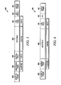
FIG. 3 illustrates several data packet configurations that may be used in connection with switch fabric networks according to the embodiments of the present invention. As described, thenetwork 22 may be configured to operate in accordance with TCP/IP, ATM, RapidIO, Infiniband and other suitable communication protocols. These data packets include structure to conform to the standard required. In one embodiment, a data packet for this invention may include adata packet 200 having aheader portion 202, apayload portion 204, and atrailer portion 206. As described herein, thenetwork 22 and the nodes 30a-h forming theswitch fabric 28 may contain processing capability. In that regard, adata packet 210 includes along with aheader portion 212,payload portion 214, andtrailer portion 216 anactive portion 218. Theactive portion 218 may cause the network element to take some specific action, for example providing alternative routing of the data packet, reconfiguration of the data packet, reconfiguration of the node, or other action, based upon the content of theactive portion 218. Thedata packet 220 includes anactive portion 228 integrated with theheader portion 222 along with apayload portion 224 and atrailer portion 226. Thedata packet 230 includes aheader portion 232, apayload portion 234 and atrailer portion 236. Anactive portion 238 is also provided, disposed between thepayload portion 234 and thetrailer portion 236. Alternatively, as shown by thedata packet 240, anactive portion 248 may be integrated with thetrailer portion 246 along with apayload portion 244 and aheader portion 242. Thedata packet 250 illustrates a firstactive portion 258 and a secondactive portion 260, wherein the firstactive portion 258 is integrated aheader portion 252 and the secondactive portion 258 is integrated with thetrailer portion 256. Thedata packet 250 also includes apayload portion 254. Other arrangements of the data packets for use with the present invention may be envisioned. - The active portion of the data packet may represent a packet state. For example, the active portion may reflect a priority of the data packet based on aging time. That is, a packet initially generated may have a normal state, but for various reasons, is not promptly delivered. As the packet ages as it is routed through the active network, the active portion can monitor time since the data packet was generated or time when the packet is required, and change the priority of the data packet accordingly. The packet state may also represent an error state, either of the data packet or of one or more nodes of the
network 22. The active portion may also be used to messenger data unrelated to the payload within thenetwork 22, track the communication path taken by the data packet through thenetwork 22, provide configuration information (route, timing, etc.) to nodes 30a-h of thenetwork 22, provide functional data to one or more devices 24a-d coupled to thenetwork 22 or provide receipt acknowledgement. - The payload portion of the data packets carries data and other information relating to the message being transmitted through the
network 22. The size of the data packet (including the payload portion) will be constrained by the physical layer on which theswitch fabric 28 is built. There are situations where the message size at the application layer will be larger than the packet size allowed to be transmitted over thenetwork 22. One situation, as described in more detail below, is where standard bus protocol messages need to be transmitted through theswitch fabric 28. Accordingly, in one embodiment of the present invention, a message in the application layer that is larger than the packet size of thenetwork 22 will be broken into smaller units to fit the packet size limitation. Each unit is placed into an individual data packet and transmitted independently over theswitch fabric 28 to a destination node. At the destination node, the individual data packets are reassembled to its original form and passed to the application that receives and processes the message. - Referring to
FIG. 4 , to illustrate the functionality and the adaptability of a node 30a-h in theswitch fabric 28, in one embodiment, a node 30a-h may have a plurality of input/output ports 50a-d although separate input and output ports could also be used. Various configurations of the node 30a-h having more or fewer ports may be used in thenetwork 22 depending on the application. The nodes 30a-h may include aprocessor 52, at least onetransceiver 54, and amemory 56. Theprocessor 52 is configured to execute instructions from software components residing in thememory 56. Although theprocessor 52 andmemory 56 are shown to be integrated with the node, in other applications, theprocess 52 andmemory 56 may be located at other places in theswitch fabric 28. Thememory 56 contains a set of software components to operate the nodes 30a-h for normal data communications and operation within theswitch fabric 28. - For nodes 30a, 30c, 30e, 30g that are connected to a legacy bus A, B, the node may further have a bus driver, a tunneling application, and a message buffer to store and transmit messages through the
switch fabric 28. For instance, when a bus protocol message arrives on a connecting node 30a, 30c, 30e, 30g, the bus driver will capture the message and store it into the message buffer where the message can be further processed by the tunneling application. The features of the tunneling application are described in more detail below. The tunneling application periodically checks if there are any new bus protocol messages coming from the port connected to the legacy bus A, B. As will be explained further below, in one embodiment, each received bus protocol message will be broken, or combined, to suit the available packet size of the underlying transmit layer of theswitch fabric network 28. Data portions such as message identification, sequence number, port number, bus data type, and data length are reserved in each data packet. If the message is being broken down, the sequence number is used to differentiate the broken segments of the legacy bus protocol message. The bus data type is used to indicate the type of bus data being transmitted over theswitch fabric 28. The same tunneling application may be used to reassemble the bus protocol message at a receiving node. - To explain these features further, the embodiment of
FIGS. 1 and2 includes applications where theswitch fabric 28 is connected to devices 24c-f through one or more standard or legacy buses A, B. For ease of transition from traditional bus architecture to the switch fabric architecture described above, it is important for theswitch fabric 28 to be able to operate seamlessly with current bus protocols. For purposes of illustrating the present invention, assume that the legacy bus A operates in accordance to the Controller Area Network (CAN) protocol and that the legacy bus B operates in accordance to the SAE J1850 Communications Standard. One of ordinary skill in the art having the benefit of this disclosure will realize that other legacy buses may be used including the Local Interconnect Network (LIN) protocol, the FLEXRAY Communications System Standard, the Media Oriented Systems Transport or MOST Protocol, or similar bus structures. The CAN protocol and the SAE J1850 Communications Standard will be used for illustration purposes. - The CAN protocol is an international standard that is based on a message oriented transmission protocol. The CAN protocol supports two message frame formats, a CAN base frame and a CAN extended frame, as will be described further below. Referring to
FIG. 5 , aCAN frame message 300 begins with a start offrame portion 302, containing a start bit, and ends with an end offrame portion 314. Between the start offrame portion 302 and the end offrame portion 314, the main fields of a typicalCAN frame message 300 includes anarbitration field 304, acontrol field 306, adata field 308, a cyclic redundant check (CRC)field 310, and an acknowledgefield 312. Thearbitration field 304 consists of an identifier and a remote transmission request bit. The length of the identifier (and the size of the arbitration field) will vary depending on whether the CAN frame message is a CAN base frame or a CAN extended frame. The CAN base frame supports a length of 11 bits for the identifier and the CAN extended frame supports a length of 29 bits for the identifier. The remote transmission request bit is used to distinguish between a data frame and a data request frame called a remote frame. - The
control field 306 of theCAN frame message 300 contains an identifier extension bit that distinguishes between the CAN base frame and the CAN extended frame. Thecontrol field 306 of aCAN frame message 300 also contains a Data Length Code (DLC) that is used to indicate the number of following data bytes in the data field. If the message is used as a remote frame, the DLC contains the number of requested data bytes. - The
data field 308 of theCAN frame message 300 is configured to hold up to 8 data bytes. After thedata field 308, theCAN frame message 300 has aCRC field 310 that contains a cyclic redundant check sum. The cyclic redundant check sum allows for errors to be checked for the incomingCAN frame message 300. The acknowledgefield 312 includes an acknowledge slot and an acknowledge delimiter. The acknowledgefield 312 is used by a receiving device to acknowledge whether data is received correctly. - The SAE J1850 Communications Standard is an international standard that is also based on a message oriented transmission protocol. The J1850 protocol supports two systems, a 41.6 kb/s Pulse Width Modulation (PWM) scheme and a 10.4 kb/s Variable Pulse Width (VPW) scheme. The VPW will be discussed for purposes of illustrating a message under the J1850 protocol. Referring to
FIG. 6 , aJ1850 frame message 400 operating under the VPW scheme begins and ends with pre-defined periods called a start offrame portion 402 and an end offrame portion 414. Between the start offrame portion 402 and the end offrame portion 414, the main fields of a typical J1850 message includes aheader field 404, adata field 408, a cyclic redundant check (CRC)field 410, and an in-frame response 412. Theheader field 304 may be one to three bytes and include bits for information such as message priority, size of header, whether an in-frame response is requested, addressing mode, and message type. - The
data field 408 of theJ1850 message 400 is configured to hold up to 8 data bytes. After thedata field 408, theJ1850 message 400 has aCRC field 410 that contains a cyclic redundant check sum. The cyclic redundant check sum allows for errors to be checked for theincoming J1850 message 400. - The in-
frame response 412 provides a mechanism for devices that receive SAE J1850 frame messages to acknowledge receipt. A bit in theheader field 304, mentioned above as an in-frame response bit, triggers the device receiving the frame message to append a reply to the end of the transmitting devices original frame message. This provides for efficient communications in that device receiving the message may respond within the same message frame as the original frame message. - The present invention allows the nodes 30a-h to be connected to different types of legacy bus protocols and tunnel the legacy bus protocol message through the
switch fabric 28. The present invention advantageously allows for a modular concept and permits nodes 30a-h to be connected to a variety of bus architectures. In one embodiment of the present invention, legacy bus protocol messages (such as theCAN frame message 300 and the J1850 message 400) are tunneled through theswitch fabric 28 protocol by dividing the messages into two or more separate units or data packets for transmission over theswitch fabric 28. As described inFIG. 3 , theswitch fabric 28 protocol may transmit a variety of data packets having specific header portions, payload portions, and trailer portion. - For purposes of illustrating the present invention, assume that the
switch fabric 28 ofFIGS. 1 and2 use data packets such as thedata packet 200 shown inFIG. 3 having aheader portion 202, apayload portion 204, and atrailer portion 206. Thisdata packet 200 does not include an active portion although an active portion may also be included (such as those shown inFIG. 3 asdata packets payload portion 204 ofswitch fabric 28 is limited to 8 bytes. - In this embodiment, as shown in
FIG. 6 , a legacy bus protocol message (such as theCAN frame message 300 and the J1850 message 400) may be divided into at least two separate data packet messages having a first payload portion 204a and a second payload portion 204b. In particular, in one embodiment, thepayload portion 204 of thedata packets 200 may be divided into amessage identification portion 260, asequence number portion 262, acontrol portion 264, and a plurality of data elements 266-276. Although the exact fields and the division of the number of bytes and bits may vary, in one example, themessage identification portion 260 may include 11 bits, thesequence number portion 262 may include 1 bit, thecontrol portion 264 may include 4 bits, and the data elements 266-276 may be each 1 byte. - The
message identification portion 260 for each of the payload portions 204a, 204b will contain a unique message identification assigned to the particular legacy bus message (for example, theCAN frame message 300 or the J1850 message 400). The message identification within theportion 260 will be the same for all payload portions 204a, 204b that are common to the same legacy bus message. The message identification is used by the nodes 30a-h to track the received data packets so that it can associated different payload portions 204a, 204b with the same legacy bus message. - The
sequence portion 262 contains a sequence number associated with the payload portions 204a, 204b. The bit(s) for thesequence number portion 262 in each payload portions 204a, 204b will be different. The bits in thesequence number portions 262 are be used by the nodes 30a-h (in conjunction with the message identification) to group the received data packets so that it can re-assemble the legacy message in the correct order. - The
control portion 264 contains information that identifies information pertaining to the particular legacy bus protocols and any other information that may help the data packet to route thedata packet 200 to the correct destination node. For instance, thecontrol portion 264 of the first payload portion 204a may include an identification of the tunneling protocol (TP) such as whether the received bus message relates to the Controller Area Network (CAN) protocol, the SAE J1850 Communications Standard, the Local Interconnect Network (LIN) protocol, the FLEXRAY Communications System Standard or similar bus structures. Thecontrol portion 264 of the first payload portion 204a may also include a port number (Port #) to help route thedata packets 200 to the correct destination. As mentioned above inFIG. 4 , the nodes 30a-h have a plurality of the input/output ports 50a-d that interconnect one node to other nodes. Thecontrol portion 264 of the second payload portion 204a may also include information regarding the length of data in the data field of the legacy bus protocol message. For example, the CAN bus protocol includes a Data Length Code (DLC) that can be used to indicate the number of data bytes in the data field. - The plurality of data elements 266-276 in the first payload portion 204a will contain any remaining portions specific to the legacy bus protocols as well as the data elements in the data fields 308, 408 of the
legacy bus messages FIG. 8 , for theCAN frame message 300, some of the data elements 266-272 in a first payload portion 284a may contain the bytes in thearbitration field 304 of theCAN frame message 300. The other data elements 274-276 may contain a first portion of the data elements in thedata field 308 of theCAN frame message 300. The data elements 266-276 in a second payload portion 284b may contain a second portion of the data elements in thedata field 308 of theCAN frame message 300. - On the other hand, as shown in
FIG. 9 , for theJ1850 message 400, some of thedata elements 266 in a first payload portion 294a may contain the byte(s) in theheader field 404 of theJ1850 message 400. The other data elements 268-276 may contain a first portion of the data elements in thedata field 408 of theJ1850 message 400. The data elements 266-276 in a second payload portion 294b may contain a second portion of the data elements in thedata field 408 of theJ1850 message 400. - In a further embodiment, the present invention includes a. mechanism for handling acknowledgments used in some legacy buses such the in-frame responses used in the J1850 frame message described above. Referring to
FIG. 10 , assume that a message needs to be transmitted from a first device 24c and tunneled through the switch fabric 28 (nodes 30a, 30c) to a second device 24e. As mentioned above, if the in-frame response bit is set in theheader field 304 of theJ1850 frame message 300, the transmitting device 24c will expect an in-frame response from the receiving device (here, node 24e). - In one embodiment, the first device 24c will broadcast an original J1850 frame message over the data bus A that interconnects the first device 24c and the first node 30a (arrow 502). The J1850 frame message may have a format similar to the
frame message 400 described inFIG. 6 . The first node 30a will receive theframe message 400 and recognize that it needs to be tunneled through theswitch fabric 28. As explained above, the first node 30a may divide the message into two or more data packets that includes payload portions 294a, 294b (example payload portions are shown inFIG. 9 ). The divided messages may then be forwarded through theswitch fabric 28 to the second node 30c (arrow 504). The second node 30c will receive the messages and reassemble payload portions 294a, 294b back into the originalJ1850 frame message 400 transmitted by the first device 24c. The second node 30c may then broadcast the message over the data bus B that interconnects the second node 30c to the second device 24e (arrow 510), assuming in this embodiment that the data bus B also operates in accordance to the SAE J1850 Communications Standard. - An issue that may arise during the above-described tunneling operation is that the first device 24c may have set a bit in the
header field 304, mentioned above as an in-frame response bit, that requires the second device 24e to reply with a response. The first node 30a may not know the correct in-frame response at the time theoriginal frame message 400 is seen at the first node 30a. The present invention solves this issue by including an application in the first device 24c that includes a retry strategy. Additionally, the method includes configuring the first node 30a, upon receipt of theoriginal message 300, to reply with a null or invalid response (arrow 508). The first device 24c will see the null or invalid response and initiate the retry strategy. Meanwhile, after the second device 24e receives the reassembledframe message 300, it will insert the correct in-frame response over the bus interconnecting the second device 24e to the second node 30c (arrow 512). The second node 30c will then tunnel the in-frame response via data packets to the first node 30a (arrow 514): The retry strategy includes a process that allows the first device 24c to broadcast a retry message, after a predetermined period, to the first node 30a (arrow 508). This will allow the first node 30a to then insert the correct in-frame response when it receives the retry message (arrow 516). - What has been described is a system and method for tunneling legacy bus protocols or other bus architecture data through an automotive switch fabric network. This is particular useful in transitioning traditional bus architectures to an automotive switch fabric network. In sum, when a bus protocol message arrives on a connecting node in the network, a bus driver in the node will capture the message and store it into a message buffer where the message can be further processed by a tunneling application. The tunneling application periodically checks if there are any new bus protocol messages coming from the port connected to the bus. Each received bus protocol message will be broken or combined to suit the available packet size of the underlying transmit layer of the switch fabric network. Data portions such as message identification, sequence number, port number, bus data type, and data length are reserved in each data packet. If the message is being broken down, the sequence number is used to differentiate the broken segments of the bus protocol message. The bus data type is used to indicate the type of bus data being transmitted over the switch fabric. The same tunneling application may be used to reassemble the bus protocol message at a receiving node.
Claims (12)
- A method for sending a bus protocol message through a switch fabric (28) of a vehicle (20) communication network, the switch fabric (28) including a plurality of nodes (30 a-h) joined by communication links for the transmission of data packets (200-250) there between, the bus protocol message having at least message data, the method comprising the steps of:receiving the bus protocol message from a standard protocol bus at a node in the switch fabric (28);generating a first data packet comprising a first message identification, a first sequence number, and a plurality of first data elements, the plurality of first data elements containing at least a first portion of the message data in the bus protocol message;generating a second data packet comprising a second message identification, a second sequence number, and a plurality of second data elements, the plurality of second data elements containing at least a second portion of th.e message data in the bus protocol message;transmitting the first data packet and the second data packet to a target node in the switch fabric (28) of the vehicle (20) communication network; receiving the first data packet and the second data packet at the target node of the vehicle (20) communication network;assembling at least the first portion of the message data and the second portion of the message data based on the first and second message identifications and the first and second sequence numbers.
- A method for sending a bus protocol message through a switch fabric (28) of a vehicle (20) communication network, the switch fabric (28) including a plurality of nodes (30 a-h) joined by communication links for the transmission of data packets (200-250) there between, the bus protocol message having at least message data, the method comprising the steps of:receiving the bus protocol message from a standard protocol bus at a node in the switch fabric (28);dividing the message data of the bus protocol message into a first data packet and a second data packet, the first data packet and the second data packet comprising:a message identification associated with the bus protocol message and a sequence number;a sequence number associated with an order of the divided message data; anda plurality of data elements, the plurality of data elements for the first data packet including at least a first portion of the message data, the plurality of the data elements for the second data packet including at least a second portion of the message data;transmitting the first and second data packets (200-250) to a target node in the switch fabric (28) of the vehicle (20) communication network;assembling at least the first portion of the message data and the second portion of the message data based on the message identification associated with the bus protocol message and the sequence numbers.
- A node in a switch fabric (28) of a vehicle (20) communication network, the switch fabric (28) including a plurality of other nodes (30 a-h) joined by communication links for the transmission of data packets (200-250) there between, the node being connected to a standard protocol bus, the node comprising:a transceiver (54) for receiving a bus protocol message from the standard protocol bus at a node in the s witch fabric (28), the bus protocol message including at least message data;a processor (52) for dividing the message data of the bus protocol message into a first data packet and a second data packet, the first data packet and the second data packet comprising:a message identification associated with the bus protocol message and a sequence number;a sequence number associated with an order of the divided message data; anda plurality of data elements, the plurality of data elements for the first data packet including at least a first portion of the message data, the plurality of the data elements for the second data packet including at least a second portion of the message data.
- The method in claim 1 or 2, or the node in claim 3, wherein the standard protocol bus operates in accordance with at least one of a Controller Area Network (CAN) protocol, a SAE J18S0 Communications Standard, a Local Interconnect Network (LIN) protocol, a FLEXRAY Communications System Standard, and a Media Oriented Systems Transport (MOST) Protocol.
- The method in claim 1 or 2, or the node in claim 3, wherein at least one of the first and second data packets (200-250) comprise a header portion (206), a payload portion (204), and a trailer portion (206), the payload portion (204) containing the message identifications (260), the sequence numbers (262), and the plurality of data elements (266-276).
- The method in claim 1 or 2, or the node in claim 3, wherein the bus protocol message requires a response to occur during a predetermined time and the node further generates a retry response message on the standard protocol bus to permit the response to occur at a later time.
- The method for sending a bus protocol message through a switch fabric (28) of a vehicle (20) communication network (22)of claim 1, wherein the bus protocol message requires a frame response to occur during a predetermined time;
the method of claim 1 further comprising:generating a retry response on the standard protocol bus to permit the frame response to occur at a later time;wherein said first sequence number and said second sequence number are associated with the payload portion (204), andwherein bits in said first sequence number and said second sequence number are used in conjunction with the message identifications to group the received data packets (200-250) to re-assemble the legacy message in a correct order. - The method in claim 7, wherein the standard protocol bus operates in accordance with a SAE 11850 Communications Standard, the frame response being associated with an in-frame response portion of the bus protocol message.
- The method in claim 8, wherein the retry response is a null or invalid response.
- The method in claim 1, 2 or 7, or the node in claim 3, wherein the standard protocol bus operates in accordance with a SAE J18S0 Communications Standard and the plurality of first data elements of the first data packet further contains data of a header field of the bus protocol message.
- The method in claim 1, 2 or 7, or the node in claim 3, wherein the first or second data packet further comprises a control field that includes an identification of a type of standard protocol bus.
- The method in claim 1, 2 or 7, or the node in claim 3, wherein the first or second data packet further comprises a control field that includes an identification of a length of the message data of the bus protocol message.
Applications Claiming Priority (3)
| Application Number | Priority Date | Filing Date | Title |
|---|---|---|---|
| US61923204P | 2004-10-15 | 2004-10-15 | |
| US11/015,606 US7599377B2 (en) | 2004-10-15 | 2004-12-17 | System and method for tunneling standard bus protocol messages through an automotive switch fabric network |
| PCT/US2005/034908 WO2006044145A2 (en) | 2004-10-15 | 2005-09-29 | System and method for tunneling standard bus protocol messages through an automotive switch fabric network |
Publications (3)
| Publication Number | Publication Date |
|---|---|
| EP1805945A2 EP1805945A2 (en) | 2007-07-11 |
| EP1805945A4 EP1805945A4 (en) | 2010-05-05 |
| EP1805945B1 true EP1805945B1 (en) | 2013-01-02 |
Family
ID=36180695
Family Applications (1)
| Application Number | Title | Priority Date | Filing Date |
|---|---|---|---|
| EP05805725A Active EP1805945B1 (en) | 2004-10-15 | 2005-09-29 | System and method for tunneling standard bus protocol messages through an automotive switch fabric network |
Country Status (4)
| Country | Link |
|---|---|
| US (1) | US7599377B2 (en) |
| EP (1) | EP1805945B1 (en) |
| JP (1) | JP2008517528A (en) |
| WO (1) | WO2006044145A2 (en) |
Families Citing this family (35)
| Publication number | Priority date | Publication date | Assignee | Title |
|---|---|---|---|---|
| DE102004038211A1 (en) * | 2004-08-05 | 2006-03-16 | Robert Bosch Gmbh | Message manager and method for controlling the access to data of a message memory of a communication module |
| US7623552B2 (en) * | 2004-10-14 | 2009-11-24 | Temic Automotive Of North America, Inc. | System and method for time synchronizing nodes in an automotive network using input capture |
| US20060083172A1 (en) * | 2004-10-14 | 2006-04-20 | Jordan Patrick D | System and method for evaluating the performance of an automotive switch fabric network |
| US7593429B2 (en) * | 2004-10-14 | 2009-09-22 | Temic Automotive Of North America, Inc. | System and method for time synchronizing nodes in an automotive network using input capture |
| US7593344B2 (en) * | 2004-10-14 | 2009-09-22 | Temic Automotive Of North America, Inc. | System and method for reprogramming nodes in an automotive switch fabric network |
| US7599377B2 (en) * | 2004-10-15 | 2009-10-06 | Temic Automotive Of North America, Inc. | System and method for tunneling standard bus protocol messages through an automotive switch fabric network |
| US7613190B2 (en) * | 2004-10-18 | 2009-11-03 | Temic Automotive Of North America, Inc. | System and method for streaming sequential data through an automotive switch fabric |
| US7733841B2 (en) * | 2005-05-10 | 2010-06-08 | Continental Automotive Systems, Inc. | Vehicle network with time slotted access and method |
| US20080046142A1 (en) * | 2006-06-29 | 2008-02-21 | Motorola, Inc. | Layered architecture supports distributed failover for applications |
| EP2064841B1 (en) * | 2006-09-06 | 2017-08-02 | Nxp B.V. | Intelligent star coupler for time triggered communication protocol and method for communicating between nodes within a network using a time trigger protocol |
| WO2008029317A2 (en) * | 2006-09-06 | 2008-03-13 | Nxp B.V. | Cluster coupler in a time triggered network |
| CN102123911B (en) * | 2006-12-25 | 2013-04-03 | 亚科夫列夫实验设计局股份公司 | Light multipurpose aircraft provided with a control integrated system |
| DE102007012304A1 (en) * | 2007-03-14 | 2008-09-18 | Robert Bosch Gmbh | Interface in a vehicle and method for data exchange |
| DE502007002941D1 (en) * | 2007-08-23 | 2010-04-08 | Siemens Ag | Method for data transmission |
| DE102007043706A1 (en) * | 2007-09-13 | 2009-03-19 | Bayerische Motoren Werke Aktiengesellschaft | Communication system for data communication between vehicle controlling devices, has multiple Flex Ray network nodes, by which internet protocol data packet is provided in each case |
| CN101437004B (en) * | 2007-11-15 | 2012-12-05 | 中兴通讯股份有限公司 | IQ data transmission method |
| TWI448111B (en) * | 2008-03-18 | 2014-08-01 | Icm Inc | Automobile detection and control integration device and method thereof |
| FR2945171B1 (en) * | 2009-04-29 | 2011-06-10 | Peugeot Citroen Automobiles Sa | METHOD FOR TRANSMITTING MESSAGES |
| DE102009050767B4 (en) * | 2009-10-27 | 2017-06-14 | Siemens Healthcare Gmbh | Method and device for data transmission |
| US9143384B2 (en) * | 2010-11-03 | 2015-09-22 | Broadcom Corporation | Vehicular network with concurrent packet transmission |
| WO2012136547A1 (en) | 2011-04-06 | 2012-10-11 | Robert Bosch Gmbh | Method and device for increasing the data transmission capacity in a serial bus system |
| EP2695073B1 (en) | 2011-04-06 | 2016-09-14 | Robert Bosch GmbH | Method and apparatus for adapting the data transmission security in a serial bus system |
| KR101936450B1 (en) | 2011-04-26 | 2019-01-08 | 로베르트 보쉬 게엠베하 | Method and device for serial data transmission which is adapted to memory sizes |
| DE102011077409A1 (en) * | 2011-06-10 | 2012-12-13 | Robert Bosch Gmbh | Connection node for a communication network |
| US9690742B2 (en) | 2011-06-29 | 2017-06-27 | Robert Bosch Gmbh | Method and device for serial data transmission having a flexible message size and a variable bit length |
| US9088514B2 (en) * | 2012-07-23 | 2015-07-21 | Broadcom Corporation | Flexray communications using ethernet |
| KR101536141B1 (en) * | 2014-02-13 | 2015-07-13 | 현대자동차주식회사 | Apparatus and method for converting signal between ethernet and can in a vehicle |
| DE102016008957B4 (en) * | 2016-07-13 | 2018-01-25 | Audi Ag | Direct access to bus signals in a motor vehicle |
| CN107257310B (en) * | 2017-07-05 | 2020-04-24 | 北京东土科技股份有限公司 | Implementation system based on industrial internet field layer broadband bus architecture |
| CN107528680B (en) * | 2017-07-05 | 2020-09-22 | 北京东土科技股份有限公司 | Real-time transmission method and device based on industrial internet field layer bus architecture |
| US10355793B2 (en) * | 2017-07-20 | 2019-07-16 | Rohde & Schwarz Gmbh & Co. Kg | Testing system and method for testing |
| KR102320043B1 (en) * | 2017-09-13 | 2021-11-01 | 현대자동차주식회사 | Failure diagnosis apparatus and method for in-vehicle control unit |
| WO2020211061A1 (en) * | 2019-04-18 | 2020-10-22 | 北京小米移动软件有限公司 | Data transmission method and device, and storage medium |
| CN111224951A (en) * | 2019-12-24 | 2020-06-02 | 广州市中海达测绘仪器有限公司 | Data processing method and device, vehicle-mounted terminal and storage medium |
| CN113938347A (en) * | 2021-09-30 | 2022-01-14 | 蜂巢能源科技有限公司 | Data interaction method and device and vehicle |
Family Cites Families (83)
| Publication number | Priority date | Publication date | Assignee | Title |
|---|---|---|---|---|
| US4805107A (en) | 1987-04-15 | 1989-02-14 | Allied-Signal Inc. | Task scheduler for a fault tolerant multiple node processing system |
| JP2851124B2 (en) | 1990-04-27 | 1999-01-27 | 古河電気工業株式会社 | Multiplex transmission method |
| US5151899A (en) * | 1991-02-11 | 1992-09-29 | Digital Equipment Corporation | Tracking sequence numbers in packet data communication system |
| US5612953A (en) | 1991-02-22 | 1997-03-18 | International Business Machines Corporation | Multi-media serial line switching adapter for parallel networks and heterogeneous and homologous computer systems |
| US5195091A (en) | 1991-07-09 | 1993-03-16 | At&T Bell Laboratories | Adaptive synchronization arrangement |
| US5196091A (en) * | 1991-10-29 | 1993-03-23 | Beloit Technologies, Inc. | Headbox apparatus with stock dilution conduits for basis weight control |
| US5566180A (en) | 1994-12-21 | 1996-10-15 | Hewlett-Packard Company | Method for recognizing events and synchronizing clocks |
| US5802052A (en) | 1996-06-26 | 1998-09-01 | Level One Communication, Inc. | Scalable high performance switch element for a shared memory packet or ATM cell switch fabric |
| US6611537B1 (en) | 1997-05-30 | 2003-08-26 | Centillium Communications, Inc. | Synchronous network for digital media streams |
| US6373834B1 (en) | 1997-12-19 | 2002-04-16 | Telefonaktiebolaget Lm Ericsson | Synchronization for cellular telecommunications network |
| US6420797B1 (en) | 1998-02-19 | 2002-07-16 | Robert Edward Steele | Electrical/electronic system architecture |
| US7035247B2 (en) | 1998-07-22 | 2006-04-25 | Synchrodyne Networks, Inc. | Link transmission control with common time reference |
| US6611519B1 (en) | 1998-08-19 | 2003-08-26 | Swxtch The Rules, Llc | Layer one switching in a packet, cell, or frame-based network |
| US7027773B1 (en) | 1999-05-28 | 2006-04-11 | Afx Technology Group International, Inc. | On/off keying node-to-node messaging transceiver network with dynamic routing and configuring |
| US6430164B1 (en) | 1999-06-17 | 2002-08-06 | Cellport Systems, Inc. | Communications involving disparate protocol network/bus and device subsystems |
| DE19931838C1 (en) * | 1999-07-09 | 2001-10-31 | Daimler Chrysler Ag | Method for checking a ring-shaped optical network line for data transmission between several network participants in a motor vehicle |
| US6356823B1 (en) | 1999-11-01 | 2002-03-12 | Itt Research Institute | System for monitoring and recording motor vehicle operating parameters and other data |
| US6757521B1 (en) | 2000-06-12 | 2004-06-29 | I/O Controls Corporation | Method and system for locating and assisting portable devices performing remote diagnostic analysis of a control network |
| US6636790B1 (en) | 2000-07-25 | 2003-10-21 | Reynolds And Reynolds Holdings, Inc. | Wireless diagnostic system and method for monitoring vehicles |
| US6845416B1 (en) * | 2000-08-02 | 2005-01-18 | National Instruments Corporation | System and method for interfacing a CAN device and a peripheral device |
| CA2419761A1 (en) | 2000-08-14 | 2002-02-21 | Audi Performance & Racing | Enhanced module chipping system |
| US6559783B1 (en) | 2000-08-16 | 2003-05-06 | Microchip Technology Incorporated | Programmable auto-converting analog to digital conversion module |
| US7463626B2 (en) | 2000-11-21 | 2008-12-09 | Roy Subhash C | Phase and frequency drift and jitter compensation in a distributed telecommunications switch |
| NO315248B1 (en) | 2000-12-15 | 2003-08-04 | Knutsen Oas Shipping As | Gas bottle device |
| JP4491967B2 (en) | 2000-12-28 | 2010-06-30 | 株式会社デンソー | VEHICLE CONTROL DEVICE AND RECORDING MEDIUM HAVING SELF-DIAGNOSTIC FUNCTION |
| US6981150B2 (en) | 2001-01-04 | 2005-12-27 | Cummins, Inc. | Apparatus and method for authorizing transfer of software into one or more embedded systems |
| US7225259B2 (en) * | 2001-02-21 | 2007-05-29 | Nokia Inc. | Service tunnel over a connectionless network |
| US8458689B2 (en) | 2001-03-30 | 2013-06-04 | Roderick A. Barman | Method and apparatus for reprogramming engine controllers |
| US7415508B2 (en) | 2001-08-31 | 2008-08-19 | Temic Automotive Of North America, Inc. | Linked vehicle active networks |
| US20030043793A1 (en) | 2001-08-31 | 2003-03-06 | Juergen Reinold | Vehicle active network |
| US7027387B2 (en) | 2001-08-31 | 2006-04-11 | Motorola, Inc. | Vehicle active network with data redundancy |
| US20030051131A1 (en) | 2001-08-31 | 2003-03-13 | Juergen Reinold | Vehicle active network with data encryption |
| US6747365B2 (en) | 2001-08-31 | 2004-06-08 | Motorola, Inc. | Vehicle active network adapted to legacy architecture |
| US7173903B2 (en) | 2001-08-31 | 2007-02-06 | Temic Automotive Of North America, Inc. | Vehicle active network with communication path redundancy |
| US20030045234A1 (en) * | 2001-08-31 | 2003-03-06 | Remboski Donald J. | Vehicle active network with reserved portions |
| US20030043824A1 (en) | 2001-08-31 | 2003-03-06 | Remboski Donald J. | Vehicle active network and device |
| US7170853B2 (en) * | 2001-08-31 | 2007-01-30 | Temic Automotive Of North America, Inc. | Vehicle active network topologies |
| US6931004B2 (en) | 2001-08-31 | 2005-08-16 | Motorola, Inc. | Vehicle active network with backbone structure |
| US8194536B2 (en) | 2001-08-31 | 2012-06-05 | Continental Automotive Systems, Inc. | Vehicle active network with fault tolerant devices |
| US6885916B2 (en) | 2001-08-31 | 2005-04-26 | Motorola, Inc. | Data packet for a vehicle active network |
| US20030065630A1 (en) | 2001-10-02 | 2003-04-03 | International Business Machines Corporation | Adjusting an amount owed for fueling based on vehicle characteristics |
| US7152385B2 (en) | 2001-10-31 | 2006-12-26 | W.R. Grace & Co.-Conn. | In situ molded thermal barriers |
| US7065651B2 (en) | 2002-01-16 | 2006-06-20 | Microsoft Corporation | Secure video card methods and systems |
| US20030185201A1 (en) | 2002-03-29 | 2003-10-02 | Dorgan John D. | System and method for 1 + 1 flow protected transmission of time-sensitive data in packet-based communication networks |
| US20040043824A1 (en) | 2002-06-08 | 2004-03-04 | Nicholas Uzelac | Swing training device |
| US20040001593A1 (en) | 2002-06-28 | 2004-01-01 | Jurgen Reinold | Method and system for component obtainment of vehicle authentication |
| US7131005B2 (en) | 2002-06-28 | 2006-10-31 | Motorola, Inc. | Method and system for component authentication of a vehicle |
| US7181615B2 (en) | 2002-06-28 | 2007-02-20 | Motorola, Inc. | Method and system for vehicle authentication of a remote access device |
| US7549046B2 (en) | 2002-06-28 | 2009-06-16 | Temic Automotive Of North America, Inc. | Method and system for vehicle authorization of a service technician |
| US7228420B2 (en) | 2002-06-28 | 2007-06-05 | Temic Automotive Of North America, Inc. | Method and system for technician authentication of a vehicle |
| US7010682B2 (en) | 2002-06-28 | 2006-03-07 | Motorola, Inc. | Method and system for vehicle authentication of a component |
| US20040003232A1 (en) | 2002-06-28 | 2004-01-01 | Levenson Samuel M. | Method and system for vehicle component authentication of another vehicle component |
| US7137001B2 (en) | 2002-06-28 | 2006-11-14 | Motorola, Inc. | Authentication of vehicle components |
| US7600114B2 (en) | 2002-06-28 | 2009-10-06 | Temic Automotive Of North America, Inc. | Method and system for vehicle authentication of another vehicle |
| US20040003234A1 (en) | 2002-06-28 | 2004-01-01 | Jurgen Reinold | Method and system for vehicle authentication of a subassembly |
| US7325135B2 (en) | 2002-06-28 | 2008-01-29 | Temic Automotive Of North America, Inc. | Method and system for authorizing reconfiguration of a vehicle |
| US7127611B2 (en) | 2002-06-28 | 2006-10-24 | Motorola, Inc. | Method and system for vehicle authentication of a component class |
| US7137142B2 (en) | 2002-06-28 | 2006-11-14 | Motorola, Inc. | Method and system for vehicle authentication of a component using key separation |
| US20040003230A1 (en) | 2002-06-28 | 2004-01-01 | Puhl Larry C. | Method and system for vehicle authentication of a service technician |
| US6839710B2 (en) | 2002-06-28 | 2005-01-04 | Motorola, Inc. | Method and system for maintaining a configuration history of a vehicle |
| US7076665B2 (en) | 2002-06-28 | 2006-07-11 | Motorola, Inc. | Method and system for vehicle subassembly authentication of a component |
| US7210063B2 (en) | 2002-08-27 | 2007-04-24 | Lsi Logic Corporation | Programmable device and method of programming |
| KR100489046B1 (en) | 2002-08-27 | 2005-05-11 | 엘지전자 주식회사 | LPA Shelf |
| US7113759B2 (en) | 2002-08-28 | 2006-09-26 | Texas Instruments Incorporated | Controller area network transceiver having capacitive balancing circuit for improved receiver common-mode rejection |
| US8305926B2 (en) * | 2002-09-04 | 2012-11-06 | At&T Intellectual Property Ii, L.P. | Method and apparatus for self-learning of call routing information |
| US8036139B2 (en) | 2002-10-28 | 2011-10-11 | Cisco Technology, Inc. | Internal BGP downloader |
| DE10261174B3 (en) * | 2002-12-20 | 2004-06-17 | Daimlerchrysler Ag | Automatic addressing method for control devices connected to data bus system with series or ring structure |
| US7792121B2 (en) | 2003-01-03 | 2010-09-07 | Microsoft Corporation | Frame protocol and scheduling system |
| US7167929B2 (en) * | 2003-01-13 | 2007-01-23 | Sierra Logic | Integrated-circuit implementation of a storage-shelf router and a path controller card for combined use in high-availability mass-storage-device shelves that may be incorporated within disk arrays, and a storage-shelf-interface tunneling method and system |
| ATE381836T1 (en) | 2003-01-23 | 2008-01-15 | Cisco Tech Inc | METHOD AND DEVICES FOR DATA TRANSMISSION BETWEEN STORAGE NETWORKS |
| US7310327B2 (en) | 2003-04-28 | 2007-12-18 | Temic Automotive Of North America, Inc. | Method and apparatus for time synchronizing an in-vehicle network |
| US7999408B2 (en) | 2003-05-16 | 2011-08-16 | Continental Automotive Systems, Inc. | Power and communication architecture for a vehicle |
| US7272496B2 (en) * | 2003-06-12 | 2007-09-18 | Temic Automotive Of North America, Inc. | Vehicle network and method of communicating data packets in a vehicle network |
| US7523237B2 (en) | 2004-04-01 | 2009-04-21 | Delphi Tecnhologies, Inc. | Method and protocol for diagnostics or arbitrarily complex networks of devices |
| US20050251608A1 (en) | 2004-05-10 | 2005-11-10 | Fehr Walton L | Vehicle network with interrupted shared access bus |
| EP1766962A4 (en) | 2004-06-22 | 2009-03-25 | Sarnoff Corp | Method and apparatus for measuring and/or correcting audio/visual synchronization |
| US7551647B2 (en) | 2004-07-19 | 2009-06-23 | Qvidium Technologies, Inc. | System and method for clock synchronization over packet-switched networks |
| US7593344B2 (en) * | 2004-10-14 | 2009-09-22 | Temic Automotive Of North America, Inc. | System and method for reprogramming nodes in an automotive switch fabric network |
| US20060083172A1 (en) * | 2004-10-14 | 2006-04-20 | Jordan Patrick D | System and method for evaluating the performance of an automotive switch fabric network |
| US7593429B2 (en) | 2004-10-14 | 2009-09-22 | Temic Automotive Of North America, Inc. | System and method for time synchronizing nodes in an automotive network using input capture |
| US7623552B2 (en) | 2004-10-14 | 2009-11-24 | Temic Automotive Of North America, Inc. | System and method for time synchronizing nodes in an automotive network using input capture |
| US7599377B2 (en) * | 2004-10-15 | 2009-10-06 | Temic Automotive Of North America, Inc. | System and method for tunneling standard bus protocol messages through an automotive switch fabric network |
| US7613190B2 (en) | 2004-10-18 | 2009-11-03 | Temic Automotive Of North America, Inc. | System and method for streaming sequential data through an automotive switch fabric |
-
2004
- 2004-12-17 US US11/015,606 patent/US7599377B2/en active Active
-
2005
- 2005-09-29 WO PCT/US2005/034908 patent/WO2006044145A2/en active Application Filing
- 2005-09-29 JP JP2007536716A patent/JP2008517528A/en active Pending
- 2005-09-29 EP EP05805725A patent/EP1805945B1/en active Active
Also Published As
| Publication number | Publication date |
|---|---|
| EP1805945A2 (en) | 2007-07-11 |
| WO2006044145A2 (en) | 2006-04-27 |
| JP2008517528A (en) | 2008-05-22 |
| EP1805945A4 (en) | 2010-05-05 |
| US7599377B2 (en) | 2009-10-06 |
| WO2006044145A3 (en) | 2006-09-08 |
| US20060083250A1 (en) | 2006-04-20 |
Similar Documents
| Publication | Publication Date | Title |
|---|---|---|
| EP1805945B1 (en) | System and method for tunneling standard bus protocol messages through an automotive switch fabric network | |
| US7272496B2 (en) | Vehicle network and method of communicating data packets in a vehicle network | |
| EP2291960B1 (en) | A method of data delivery across a network | |
| US7593344B2 (en) | System and method for reprogramming nodes in an automotive switch fabric network | |
| CN108370336B (en) | Electronic control unit, frame generation method, and recording medium | |
| US7623552B2 (en) | System and method for time synchronizing nodes in an automotive network using input capture | |
| US6438128B1 (en) | Alternate use of data packet fields to convey information | |
| WO2006044122A2 (en) | System and method for streaming sequential data through an automotive switch fabric network | |
| US7733841B2 (en) | Vehicle network with time slotted access and method | |
| US20060083172A1 (en) | System and method for evaluating the performance of an automotive switch fabric network | |
| WO2003021895A1 (en) | Vehicle active network adapted to specific architecture | |
| US6885916B2 (en) | Data packet for a vehicle active network | |
| WO2003021898A1 (en) | Vehicle active network with redundant devices | |
| WO2003021894A1 (en) | Vehicle active network with communication path redundancy | |
| WO2007063585A1 (en) | Communication device and frame control method | |
| WO2003021889A1 (en) | Vehicle active network using multiple communication paths | |
| WO2003021879A1 (en) | Vehicle active network topologies | |
| WO2003021896A1 (en) | Vehicle active network with fault tolerant devices | |
| US20030182440A1 (en) | Network processor with high-speed transceiver | |
| WO2003021867A2 (en) | Linked vehicle active networks | |
| JP7400820B2 (en) | In-vehicle communication system, in-vehicle device and vehicle communication method | |
| WO2003021897A1 (en) | Vehicle active network with backbone structure | |
| WO2003021881A1 (en) | Vehicle active network with data encryption | |
| WO2003021892A1 (en) | Vehicle active network with reserved portions | |
| KR20220031008A (en) | Methods and data networks for communicating data content in particular in elevator systems |
Legal Events
| Date | Code | Title | Description |
|---|---|---|---|
| PUAI | Public reference made under article 153(3) epc to a published international application that has entered the european phase |
Free format text: ORIGINAL CODE: 0009012 |
|
| 17P | Request for examination filed |
Effective date: 20070427 |
|
| AK | Designated contracting states |
Kind code of ref document: A2 Designated state(s): AT BE BG CH CY CZ DE DK EE ES FI FR GB GR HU IE IS IT LI LT LU LV MC NL PL PT RO SE SI SK TR |
|
| DAX | Request for extension of the european patent (deleted) | ||
| A4 | Supplementary search report drawn up and despatched |
Effective date: 20100409 |
|
| RIC1 | Information provided on ipc code assigned before grant |
Ipc: H04L 12/40 20060101AFI20100401BHEP Ipc: H04L 12/56 20060101ALI20100401BHEP Ipc: H04L 12/46 20060101ALI20100401BHEP |
|
| GRAP | Despatch of communication of intention to grant a patent |
Free format text: ORIGINAL CODE: EPIDOSNIGR1 |
|
| RAP1 | Party data changed (applicant data changed or rights of an application transferred) |
Owner name: CONTINENTAL AUTOMOTIVE SYSTEMS, INC. |
|
| GRAS | Grant fee paid |
Free format text: ORIGINAL CODE: EPIDOSNIGR3 |
|
| REG | Reference to a national code |
Ref country code: DE Ref legal event code: R079 Ref document number: 602005037748 Country of ref document: DE Free format text: PREVIOUS MAIN CLASS: H04L0012500000 Ipc: H04L0012400000 |
|
| GRAA | (expected) grant |
Free format text: ORIGINAL CODE: 0009210 |
|
| AK | Designated contracting states |
Kind code of ref document: B1 Designated state(s): AT BE BG CH CY CZ DE DK EE ES FI FR GB GR HU IE IS IT LI LT LU LV MC NL PL PT RO SE SI SK TR |
|
| REG | Reference to a national code |
Ref country code: GB Ref legal event code: FG4D |
|
| RIC1 | Information provided on ipc code assigned before grant |
Ipc: H04L 12/64 20060101ALI20121128BHEP Ipc: H04L 12/40 20060101AFI20121128BHEP Ipc: H04L 12/46 20060101ALI20121128BHEP |
|
| REG | Reference to a national code |
Ref country code: CH Ref legal event code: EP Ref country code: AT Ref legal event code: REF Ref document number: 592119 Country of ref document: AT Kind code of ref document: T Effective date: 20130115 |
|
| REG | Reference to a national code |
Ref country code: IE Ref legal event code: FG4D |
|
| REG | Reference to a national code |
Ref country code: DE Ref legal event code: R096 Ref document number: 602005037748 Country of ref document: DE Effective date: 20130228 |
|
| REG | Reference to a national code |
Ref country code: AT Ref legal event code: MK05 Ref document number: 592119 Country of ref document: AT Kind code of ref document: T Effective date: 20130102 |
|
| REG | Reference to a national code |
Ref country code: NL Ref legal event code: VDEP Effective date: 20130102 |
|
| PG25 | Lapsed in a contracting state [announced via postgrant information from national office to epo] |
Ref country code: SI Free format text: LAPSE BECAUSE OF FAILURE TO SUBMIT A TRANSLATION OF THE DESCRIPTION OR TO PAY THE FEE WITHIN THE PRESCRIBED TIME-LIMIT Effective date: 20130102 |
|
| REG | Reference to a national code |
Ref country code: LT Ref legal event code: MG4D |
|
| PG25 | Lapsed in a contracting state [announced via postgrant information from national office to epo] |
Ref country code: LT Free format text: LAPSE BECAUSE OF FAILURE TO SUBMIT A TRANSLATION OF THE DESCRIPTION OR TO PAY THE FEE WITHIN THE PRESCRIBED TIME-LIMIT Effective date: 20130102 Ref country code: BG Free format text: LAPSE BECAUSE OF FAILURE TO SUBMIT A TRANSLATION OF THE DESCRIPTION OR TO PAY THE FEE WITHIN THE PRESCRIBED TIME-LIMIT Effective date: 20130402 Ref country code: ES Free format text: LAPSE BECAUSE OF FAILURE TO SUBMIT A TRANSLATION OF THE DESCRIPTION OR TO PAY THE FEE WITHIN THE PRESCRIBED TIME-LIMIT Effective date: 20130413 Ref country code: BE Free format text: LAPSE BECAUSE OF FAILURE TO SUBMIT A TRANSLATION OF THE DESCRIPTION OR TO PAY THE FEE WITHIN THE PRESCRIBED TIME-LIMIT Effective date: 20130102 Ref country code: SE Free format text: LAPSE BECAUSE OF FAILURE TO SUBMIT A TRANSLATION OF THE DESCRIPTION OR TO PAY THE FEE WITHIN THE PRESCRIBED TIME-LIMIT Effective date: 20130102 Ref country code: IS Free format text: LAPSE BECAUSE OF FAILURE TO SUBMIT A TRANSLATION OF THE DESCRIPTION OR TO PAY THE FEE WITHIN THE PRESCRIBED TIME-LIMIT Effective date: 20130502 Ref country code: CZ Free format text: LAPSE BECAUSE OF FAILURE TO SUBMIT A TRANSLATION OF THE DESCRIPTION OR TO PAY THE FEE WITHIN THE PRESCRIBED TIME-LIMIT Effective date: 20130102 Ref country code: AT Free format text: LAPSE BECAUSE OF FAILURE TO SUBMIT A TRANSLATION OF THE DESCRIPTION OR TO PAY THE FEE WITHIN THE PRESCRIBED TIME-LIMIT Effective date: 20130102 |
|
| PG25 | Lapsed in a contracting state [announced via postgrant information from national office to epo] |
Ref country code: GR Free format text: LAPSE BECAUSE OF FAILURE TO SUBMIT A TRANSLATION OF THE DESCRIPTION OR TO PAY THE FEE WITHIN THE PRESCRIBED TIME-LIMIT Effective date: 20130403 Ref country code: NL Free format text: LAPSE BECAUSE OF FAILURE TO SUBMIT A TRANSLATION OF THE DESCRIPTION OR TO PAY THE FEE WITHIN THE PRESCRIBED TIME-LIMIT Effective date: 20130102 Ref country code: PT Free format text: LAPSE BECAUSE OF FAILURE TO SUBMIT A TRANSLATION OF THE DESCRIPTION OR TO PAY THE FEE WITHIN THE PRESCRIBED TIME-LIMIT Effective date: 20130502 Ref country code: LV Free format text: LAPSE BECAUSE OF FAILURE TO SUBMIT A TRANSLATION OF THE DESCRIPTION OR TO PAY THE FEE WITHIN THE PRESCRIBED TIME-LIMIT Effective date: 20130102 Ref country code: PL Free format text: LAPSE BECAUSE OF FAILURE TO SUBMIT A TRANSLATION OF THE DESCRIPTION OR TO PAY THE FEE WITHIN THE PRESCRIBED TIME-LIMIT Effective date: 20130102 Ref country code: FI Free format text: LAPSE BECAUSE OF FAILURE TO SUBMIT A TRANSLATION OF THE DESCRIPTION OR TO PAY THE FEE WITHIN THE PRESCRIBED TIME-LIMIT Effective date: 20130102 |
|
| PG25 | Lapsed in a contracting state [announced via postgrant information from national office to epo] |
Ref country code: SK Free format text: LAPSE BECAUSE OF FAILURE TO SUBMIT A TRANSLATION OF THE DESCRIPTION OR TO PAY THE FEE WITHIN THE PRESCRIBED TIME-LIMIT Effective date: 20130102 Ref country code: RO Free format text: LAPSE BECAUSE OF FAILURE TO SUBMIT A TRANSLATION OF THE DESCRIPTION OR TO PAY THE FEE WITHIN THE PRESCRIBED TIME-LIMIT Effective date: 20130102 Ref country code: DK Free format text: LAPSE BECAUSE OF FAILURE TO SUBMIT A TRANSLATION OF THE DESCRIPTION OR TO PAY THE FEE WITHIN THE PRESCRIBED TIME-LIMIT Effective date: 20130102 Ref country code: EE Free format text: LAPSE BECAUSE OF FAILURE TO SUBMIT A TRANSLATION OF THE DESCRIPTION OR TO PAY THE FEE WITHIN THE PRESCRIBED TIME-LIMIT Effective date: 20130102 |
|
| PLBE | No opposition filed within time limit |
Free format text: ORIGINAL CODE: 0009261 |
|
| STAA | Information on the status of an ep patent application or granted ep patent |
Free format text: STATUS: NO OPPOSITION FILED WITHIN TIME LIMIT |
|
| PG25 | Lapsed in a contracting state [announced via postgrant information from national office to epo] |
Ref country code: CY Free format text: LAPSE BECAUSE OF FAILURE TO SUBMIT A TRANSLATION OF THE DESCRIPTION OR TO PAY THE FEE WITHIN THE PRESCRIBED TIME-LIMIT Effective date: 20130102 |
|
| 26N | No opposition filed |
Effective date: 20131003 |
|
| PG25 | Lapsed in a contracting state [announced via postgrant information from national office to epo] |
Ref country code: IT Free format text: LAPSE BECAUSE OF FAILURE TO SUBMIT A TRANSLATION OF THE DESCRIPTION OR TO PAY THE FEE WITHIN THE PRESCRIBED TIME-LIMIT Effective date: 20130102 |
|
| REG | Reference to a national code |
Ref country code: DE Ref legal event code: R097 Ref document number: 602005037748 Country of ref document: DE Effective date: 20131003 |
|
| PG25 | Lapsed in a contracting state [announced via postgrant information from national office to epo] |
Ref country code: MC Free format text: LAPSE BECAUSE OF FAILURE TO SUBMIT A TRANSLATION OF THE DESCRIPTION OR TO PAY THE FEE WITHIN THE PRESCRIBED TIME-LIMIT Effective date: 20130102 |
|
| REG | Reference to a national code |
Ref country code: CH Ref legal event code: PL |
|
| GBPC | Gb: european patent ceased through non-payment of renewal fee |
Effective date: 20130929 |
|
| REG | Reference to a national code |
Ref country code: FR Ref legal event code: ST Effective date: 20140530 |
|
| REG | Reference to a national code |
Ref country code: IE Ref legal event code: MM4A |
|
| PG25 | Lapsed in a contracting state [announced via postgrant information from national office to epo] |
Ref country code: IE Free format text: LAPSE BECAUSE OF NON-PAYMENT OF DUE FEES Effective date: 20130929 Ref country code: CH Free format text: LAPSE BECAUSE OF NON-PAYMENT OF DUE FEES Effective date: 20130930 Ref country code: GB Free format text: LAPSE BECAUSE OF NON-PAYMENT OF DUE FEES Effective date: 20130929 Ref country code: LI Free format text: LAPSE BECAUSE OF NON-PAYMENT OF DUE FEES Effective date: 20130930 |
|
| PG25 | Lapsed in a contracting state [announced via postgrant information from national office to epo] |
Ref country code: FR Free format text: LAPSE BECAUSE OF NON-PAYMENT OF DUE FEES Effective date: 20130930 |
|
| PG25 | Lapsed in a contracting state [announced via postgrant information from national office to epo] |
Ref country code: TR Free format text: LAPSE BECAUSE OF FAILURE TO SUBMIT A TRANSLATION OF THE DESCRIPTION OR TO PAY THE FEE WITHIN THE PRESCRIBED TIME-LIMIT Effective date: 20130102 |
|
| PG25 | Lapsed in a contracting state [announced via postgrant information from national office to epo] |
Ref country code: LU Free format text: LAPSE BECAUSE OF NON-PAYMENT OF DUE FEES Effective date: 20130929 Ref country code: HU Free format text: LAPSE BECAUSE OF FAILURE TO SUBMIT A TRANSLATION OF THE DESCRIPTION OR TO PAY THE FEE WITHIN THE PRESCRIBED TIME-LIMIT; INVALID AB INITIO Effective date: 20050929 |
|
| PGFP | Annual fee paid to national office [announced via postgrant information from national office to epo] |
Ref country code: DE Payment date: 20230930 Year of fee payment: 19 |