EP1805414B1 - Gründung für eine offshore-windkraftanlage - Google Patents
Gründung für eine offshore-windkraftanlage Download PDFInfo
- Publication number
- EP1805414B1 EP1805414B1 EP04786200.8A EP04786200A EP1805414B1 EP 1805414 B1 EP1805414 B1 EP 1805414B1 EP 04786200 A EP04786200 A EP 04786200A EP 1805414 B1 EP1805414 B1 EP 1805414B1
- Authority
- EP
- European Patent Office
- Prior art keywords
- foundation
- support frame
- pipes
- free ends
- foundation pipes
- Prior art date
- Legal status (The legal status is an assumption and is not a legal conclusion. Google has not performed a legal analysis and makes no representation as to the accuracy of the status listed.)
- Expired - Lifetime
Links
- 239000011796 hollow space material Substances 0.000 claims 3
- XLYOFNOQVPJJNP-UHFFFAOYSA-N water Substances O XLYOFNOQVPJJNP-UHFFFAOYSA-N 0.000 description 5
- 238000010276 construction Methods 0.000 description 4
- 230000007797 corrosion Effects 0.000 description 2
- 238000005260 corrosion Methods 0.000 description 2
- 229910000831 Steel Inorganic materials 0.000 description 1
- 238000004873 anchoring Methods 0.000 description 1
- 230000007423 decrease Effects 0.000 description 1
- 238000006073 displacement reaction Methods 0.000 description 1
- 239000007787 solid Substances 0.000 description 1
- 239000010959 steel Substances 0.000 description 1
Images
Classifications
-
- E—FIXED CONSTRUCTIONS
- E02—HYDRAULIC ENGINEERING; FOUNDATIONS; SOIL SHIFTING
- E02D—FOUNDATIONS; EXCAVATIONS; EMBANKMENTS; UNDERGROUND OR UNDERWATER STRUCTURES
- E02D27/00—Foundations as substructures
- E02D27/32—Foundations for special purposes
- E02D27/52—Submerged foundations, i.e. submerged in open water
-
- E—FIXED CONSTRUCTIONS
- E02—HYDRAULIC ENGINEERING; FOUNDATIONS; SOIL SHIFTING
- E02D—FOUNDATIONS; EXCAVATIONS; EMBANKMENTS; UNDERGROUND OR UNDERWATER STRUCTURES
- E02D27/00—Foundations as substructures
- E02D27/32—Foundations for special purposes
- E02D27/42—Foundations for poles, masts or chimneys
- E02D27/425—Foundations for poles, masts or chimneys specially adapted for wind motors masts
-
- F—MECHANICAL ENGINEERING; LIGHTING; HEATING; WEAPONS; BLASTING
- F03—MACHINES OR ENGINES FOR LIQUIDS; WIND, SPRING, OR WEIGHT MOTORS; PRODUCING MECHANICAL POWER OR A REACTIVE PROPULSIVE THRUST, NOT OTHERWISE PROVIDED FOR
- F03D—WIND MOTORS
- F03D13/00—Assembly, mounting or commissioning of wind motors; Arrangements specially adapted for transporting wind motor components
- F03D13/20—Arrangements for mounting or supporting wind motors; Masts or towers for wind motors
- F03D13/22—Foundations specially adapted for wind motors
-
- E—FIXED CONSTRUCTIONS
- E02—HYDRAULIC ENGINEERING; FOUNDATIONS; SOIL SHIFTING
- E02B—HYDRAULIC ENGINEERING
- E02B17/00—Artificial islands mounted on piles or like supports, e.g. platforms on raisable legs or offshore constructions; Construction methods therefor
- E02B2017/0091—Offshore structures for wind turbines
-
- F—MECHANICAL ENGINEERING; LIGHTING; HEATING; WEAPONS; BLASTING
- F05—INDEXING SCHEMES RELATING TO ENGINES OR PUMPS IN VARIOUS SUBCLASSES OF CLASSES F01-F04
- F05B—INDEXING SCHEME RELATING TO WIND, SPRING, WEIGHT, INERTIA OR LIKE MOTORS, TO MACHINES OR ENGINES FOR LIQUIDS COVERED BY SUBCLASSES F03B, F03D AND F03G
- F05B2240/00—Components
- F05B2240/90—Mounting on supporting structures or systems
- F05B2240/95—Mounting on supporting structures or systems offshore
-
- Y—GENERAL TAGGING OF NEW TECHNOLOGICAL DEVELOPMENTS; GENERAL TAGGING OF CROSS-SECTIONAL TECHNOLOGIES SPANNING OVER SEVERAL SECTIONS OF THE IPC; TECHNICAL SUBJECTS COVERED BY FORMER USPC CROSS-REFERENCE ART COLLECTIONS [XRACs] AND DIGESTS
- Y02—TECHNOLOGIES OR APPLICATIONS FOR MITIGATION OR ADAPTATION AGAINST CLIMATE CHANGE
- Y02E—REDUCTION OF GREENHOUSE GAS [GHG] EMISSIONS, RELATED TO ENERGY GENERATION, TRANSMISSION OR DISTRIBUTION
- Y02E10/00—Energy generation through renewable energy sources
- Y02E10/70—Wind energy
- Y02E10/72—Wind turbines with rotation axis in wind direction
-
- Y—GENERAL TAGGING OF NEW TECHNOLOGICAL DEVELOPMENTS; GENERAL TAGGING OF CROSS-SECTIONAL TECHNOLOGIES SPANNING OVER SEVERAL SECTIONS OF THE IPC; TECHNICAL SUBJECTS COVERED BY FORMER USPC CROSS-REFERENCE ART COLLECTIONS [XRACs] AND DIGESTS
- Y02—TECHNOLOGIES OR APPLICATIONS FOR MITIGATION OR ADAPTATION AGAINST CLIMATE CHANGE
- Y02E—REDUCTION OF GREENHOUSE GAS [GHG] EMISSIONS, RELATED TO ENERGY GENERATION, TRANSMISSION OR DISTRIBUTION
- Y02E10/00—Energy generation through renewable energy sources
- Y02E10/70—Wind energy
- Y02E10/727—Offshore wind turbines
Definitions
- the present invention relates to a foundation according to the preamble of claim 1.
- a foundation of the type mentioned is from the DE 201 09 981 U1 known.
- the known foundation of the support structure is designed as a spatial framework, which is located above the expected swell.
- the truss is provided at its n corners each with a corner tube, which are aligned with the foundation pipes, and the joint between the corner pipes and the foundation pipes is located above the sea level.
- the foundation with the wind turbine mounted thereon can be considered as a mechanical system anchored as a boom with a point weight (rotor and nacelle) at the tip of the boom in the seabed.
- a point weight rotor and nacelle
- the natural frequency of such a system decreases significantly.
- the natural frequency of the system must be raised to a suitable frequency range for the respective wind turbine.
- the distance between the point weight (rotor and nacelle) and the anchoring in the seabed in the case of wind turbines, which are used at water depths of about 50m, is significantly greater than in the case of already Existing wind turbines, which are used at shallower water depths, becoming increasingly difficult to achieve the required natural frequencies.
- An additional difficulty is that ever more powerful wind turbines are used, in which the rotor and nacelle weight is much greater than in the case of existing prototypes.
- the invention is therefore an object of the invention to provide a technically easier at water depths in the range of about 30m to about 50m deployable foundation.
- this object is achieved in the generic foundation in that the support framework consists of radial struts with non-slotted profile and at least the underside of the support structure below the expected swell, but above the Sea level is arranged and rigid connections between the scaffold and the free ends of the foundation pipes are provided.
- the radial struts have an outward change on the cross section.
- a rigid connection is intended to mean a connection which is as rigid as is structurally possible and which largely prevents displacements of the connected elements from one another.
- a non-slotted profile may also be referred to as a closed profile, such as a rectangular or cylindrical profile.
- the arrangement of at least the underside of the support structure below the expected wave height (expected wave) and the execution of the scaffold as a radial construction with minimum height makes it possible to lower the wind turbine with rotor and nacelle, whereby the achievement of the required natural frequencies is simplified, at which resonances are excluded with the rotor frequencies.
- the rigidity of the connection between the scaffold and the free ends of the rammed into the seabed foundation pipes increases the rigidity of the existing foundation and wind turbine system; the achievement of the required natural frequencies is also facilitated.
- n 3.
- n 4.
- connections between the free ends of the foundation pipes and the support frame comprise sockets which are firmly and rigidly connected to the support frame and which are inserted into the free ends of the foundation pipes with a cavity between the walls of the foundation pipes and the sockets are, with the cavity is shed.
- the cavity consists of the annular gap in the radial direction between the respective inner and outer elements (nozzle / foundation tube) and the space in the longitudinal direction between the ends of the elements
- connections between the free ends of the foundation pipes and the support frame comprise stubs which are firmly and rigidly connected to the support frame and the free ends of the foundation pipes from the outside with a cavity between the walls of the stubs and the foundation pipes are plugged, wherein the cavity is potted.
- an upright tower receiving element with a cylindrical-conical shape and a connection for the tower is arranged centrally in the support structure, which is firmly connected by the radial struts with the nozzle.
- the support structure is arranged wholly or partially above the splash zone.
- the invention is based on the surprising finding that the natural frequencies of the system consisting of foundations and wind turbines are significantly more easily raised to an area due to the special design and arrangement of the support structure in combination with the rigid connections between the free ends of the foundation pipes with the support structure can be excluded, in which resonances with the rotor frequencies are excluded, which is particularly relevant for wind turbines, which are used at water depths of about 30m to 50m.
- the arrangement of at least the underside of the support structure below the expected wave height (the expected swell) and according to a particular embodiment wholly or partially above the splash zone, which is characterized by increased corrosion of the construction, represents a compromise between the desire, the construction Protect against wave action and thus reduce the forces acting on the waves, on the one hand and the need to ensure certain natural frequencies in the construction, on the other hand dar.
- a turn-receiving element 22 is arranged with a cylindrical-conical shape and a connection 6.
- the tower receiving element 22 is fixedly connected to the radial struts 7.
- the free ends of the foundation pipes 2 are rigidly connected to the scaffold.
- the rigid connections 12 comprise stubs 4, which are inserted into the free ends of the foundation pipes 2 with play, that is, with a cavity.
- the connections between the foundation pipes 2 and the nozzle 4 are solid, stiff and resilient, the cavity is shed for example with concrete 10.
- FIG. 4 comprising the connections 12 stubs 4, which are put on the free ends of the foundation pipes 2 with play, that is, with a cavity.
- the cavity is in turn potted with concrete 10, for example.
- connections 12 may be identical at all corners, that is different than in FIG FIG. 2 shown.
- a rigid connection between the support structure 1 and the foundation tubes 2 increases the strength of the foundation with a wind turbine mounted thereon, of which only the tower 5 - and only partially - is shown, thus achieving a lying above a required minimum value first natural frequency of the foundation is simplified.
- the arrangement of the support structure 1 with its bottom 27 below the expected wave 25, which corresponds to the expected maximum wave height, but above the sea level 26 allows to reduce the height at which the tower 5 is connected to the support structure 1, and also to install the wind turbine lower. This additionally simplifies the achievement of the required (higher) natural frequency.
- the execution of the scaffold 1 with radial struts 7 makes it possible to reduce the height of the support structure and thus the connection between the support structure 1 and the tower 5 and to lower the wind turbine.
Landscapes
- Engineering & Computer Science (AREA)
- Life Sciences & Earth Sciences (AREA)
- General Engineering & Computer Science (AREA)
- Mining & Mineral Resources (AREA)
- Paleontology (AREA)
- Civil Engineering (AREA)
- General Life Sciences & Earth Sciences (AREA)
- Structural Engineering (AREA)
- Sustainable Development (AREA)
- Sustainable Energy (AREA)
- Chemical & Material Sciences (AREA)
- Combustion & Propulsion (AREA)
- Mechanical Engineering (AREA)
- Wind Motors (AREA)
Description
- Die vorliegende Erfindung betrifft eine Gründung gemäß dem Oberbegriff von Anspruch 1.
- Eine Gründung der eingangs genannten Art ist aus der
DE 201 09 981 U1 bekannt. Bei der bekannten Gründung ist die Stützstruktur als räumliches Fachwerk ausgebildet, das oberhalb des zu erwartenden Wellengangs angeordnet ist. Das Fachwerk ist an seinen n Ecken jeweils mit einem Eckrohr versehen, die mit den Gründungsrohren fluchten, und die Stoßstelle zwischen den Eckrohren und den Gründungsrohren ist oberhalb des Meeresspiegels angeordnet. - Aus der
DE 100 61 916 A1 ist eine Gründung für eine Offshore-Windkraftanlage mit n an den Ecken eines gedachten regelmäßigen Vielecks in den Meeresboden eingerammten Gründungsrohren und mit einer den Turm der Windkraftanlage tragenden n-eckigen Stützstruktur bekannt, bei der zwischen der Stützstruktur und den freien Enden der Gründungsrohre angeordnete, ein Verschwenken des Stützgerüstes in alle Richtungen um die aufrecht stehenden Gründungsrohre erlaubende Gelenke vorgesehen sind. - Darüber hinaus wird in Hau, Windkraftanlagen, Springer Verlag, dritte Auflage, Seite 624, Bild 17.20, eine Tripod-Gründung gezeigt. Die bekannte Gründung weist ein zentrales Rohr mit drei rohrförmigen Schrägstützen auf. Horizontal verlaufende Rohre verbinden die unteren Enden der Schrägstützen miteinander und mit dem zentralen Rohr. In der Regel werden die drei Auflagepunkte mit dünneren Stahlrohren im Meeresboden verankert. Schrägstreben und Gurte aus Querstreben sowie Verbindungen zwischen der Stützstruktur und den Gründungsrohren liegen unterhalb des Meeresspiegels.
- Die Gründung mit der darauf befestigten Windkraftanlage kann als ein mechanisches System angesehen werden, das als ein Ausleger mit einem Punktgewicht (Rotor und Gondel) an der Spitze des Auslegers im Meeresboden verankert ist. Mit zunehmendem Abstand zwischen dem Punktgewicht an der Spitze des Auslegers und der Verankerung verringert sich die Eigenfrequenz eines solchen Systems deutlich. Zur Vermeidung von Resonanz mit den Rotorfrequenzen muß die Eigenfrequenz des Systems in einen für die jeweilige Windkraftanlage geeigneten Frequenzbereich angehoben werden. Dabei ist zu beachten, daß verglichen mit den bereits existierenden Prototypen der Abstand zwischen dem Punktgewicht (Rotor und Gondel) und der Verankerung im Meeresboden im Falle von Windkraftanlagen, die bei Wassertiefen von ca. 50m eingesetzt werden, deutlich größer ist als im Falle von bereits existierenden Windkraftanlagen, die bei geringeren Wassertiefen eingesetzt werden, wobei immer schwieriger wird, die erforderlichen Eigenfrequenzen zu erreichen. Eine zusätzliche Schwierigkeit besteht darin, daß immer leistungsstärkere Windkraftanlagen zum Einsatz kommen, bei denen das Rotor- und Gondelgewicht wesentlich größer ist, als im Falle der bereits existierenden Prototypen.
- Der Erfindung liegt somit die Aufgabe zugrunde, eine technisch einfachere bei Wassertiefen im Bereich von ca. 30m bis ca. 50m einsetzbare Gründung zu schaffen.
- Erfindungsgemäß wird diese Aufgabe bei der gattungsgemäßen Gründung dadurch gelöst, daß das Stützgerüst aus Radialstreben mit nicht geschlitztem Profil besteht und zumindest die Unterseite der Stützstruktur unterhalb des zu erwartenden Wellengangs, jedoch über dem Meeresspiegel angeordnet ist sowie steife Verbindungen zwischen dem Stützgerüst und den freien Enden der Gründungsrohre vorgesehen sind. Erfindungsgemäß weisen die Radialstreben einen nach außen such verändern den Querschnitt auf.
- Mit einer steifen Verbindung soll eine Verbindung gemeint sein, die so steif, wie dies konstruktiv möglich ist, ausgebildet ist und Verschiebungen der verbundenen Elemente gegeneinander weitestgehend ausschließt.
- Ein nicht geschlitztes Profil kann auch als geschlossenes Profil, wie zum Beispiel ein rechteckiges oder zylindrisches Profil, bezeichnet werden.
- Die Anordnung zumindest der Unterseite der Stützstruktur unterhalb der zu erwartenden Wellenhöhe (des zu erwartenden Wellengangs) und die Ausführung des Stützgerüstes als radiale Konstruktion mit minimaler Höhe erlaubt es, die Windkraftanlage mit Rotor und Gondel abzusenken, wodurch das Erreichen der erforderlichen Eigenfrequenzen vereinfacht wird, bei welchen Resonanzen mit den Rotorfrequenzen ausgeschlossen sind.
- Durch die Steifigkeit der Verbindung zwischen Stützgerüst und den freien Enden der in den Meeresboden gerammten Gründungsrohre erhöht sich die Steifigkeit des aus Gründung und Windkraftanlage bestehenden Systems; das Erreichen der erforderlichen Eigenfrequenzen wird ebenfalls erleichtert.
- Gemäß einer ersten besonderen Ausführungsform der Erfindung kann vorgesehen sein, daß n=3 ist.
- Alternativ kann vorgesehen sein, daß n=4 ist.
- GemäB der Erfindung ist vorgesehen, daß die Verbindungen zwischen den freien Enden der Gründungsrohre und dem Stützgerüst Stutzen umfassen, die fest und steif mit dem Stützgerüst verbunden sind und die in die freien Enden der Gründungsrohre mit einem Hohlraum zwischen den Wänden der Gründungsrohre und den Stutzen gesteckt sind, wobei der Hohlraum vergossen ist. Der Hohlraum besteht aus dem Ringspalt in radialer Richtung zwischen den jeweiligen inneren und äußeren Elementen (Stutzen/Gründungsrohr) und dem Raum in Längsrichtung zwischen den Enden der Elemente
- Alternativ ist erfindungsgemäß vorgesehen, daß die Verbindungen zwischen den freien Enden der Gründungsrohre und dem Stützgerüst Stutzen umfassen, die fest und steif mit dem Stützgerüst verbunden sind und die auf die freien Enden der Gründungsrohre von außen mit einem Hohlraum zwischen den Wänden der Stutzen und den Gründungsrohren gesteckt sind, wobei der Hohlraum vergossen ist.
- Günstigerweise ist in der Stützstruktur ein aufrecht angeordnetes Turmaufnahmeelement mit zylindrisch-konischer Gestalt und einer Verbindung für den Turm zentral angeordnet ist, welches durch die Radialstreben mit den Stutzen fest verbunden.
- Gemäß einer weiteren besonderen Ausführungsform der Erfindung ist die Stützstruktur ganz oder teilweise oberhalb der Splash-Zone angeordnet.
- Der Erfindung liegt die überraschende Erkenntnis zugrunde, daß durch die spezielle Gestaltung und Anordnung der Stützstruktur in Kombination mit den steifen Verbindungen zwischen den freien Enden der Gründungsrohre mit der Stützstruktur die Eigenfrequenzen des Systems aus Gründung und Windkraftanlage deutlich einfacher in einen Bereich angehoben werden können, in dem Resonanzen mit den Rotorfrequenzen ausgeschlossen sind, was für Windkraftanlagen, die bei Wassertiefen von ca. 30m bis 50m verwendet werden, besonders aktuell ist.
- Das Absenken des Stützgerüstes und seine minimale Höhe, die dadurch erreicht wird, dass das Stützgerüst aus Radialstreben mit nicht geschlitztem Profil und nicht als Rahmen wie aus der
DE 201 09 981 U1 bekannt; mit steifen Verbindungen zwischen Stützgerüst und Gründungsrohren gegenüber dem ausDE 10061916 A1 bekannten Fachwerk mit Gelenkverbindungen; die Anordnung der Verbindungen zwischen den Gründungsrohren und dem Stützgerüst über dem Meeresspiegel und nicht unter Wasser, wie beim Prototypen aus dem Buch von E. Hau - all das führt dazu, dass die erforderlichen Eigenfrequenzen einfacher erreicht werden können. - Die Anordnung zumindest der Unterseite der Stützstruktur unterhalb der zu erwartenden Wellenhöhe (des zu erwartenden Wellengangs) und gemäß einer besonderen Ausführungsform ganz oder teilweise oberhalb der Splash-Zone, die durch erhöhte Korrosion der Konstruktion gekennzeichnet ist, stellt einen Kompromiß zwischen dem Wunsch, die Konstruktion vor Welleneinwirkung zu schützen und somit die einwirkenden Kräfte der Wellen zu verringern, einerseits und der Notwendigkeit, bestimmte Eigenfrequenzen in der Konstruktion zu gewährleisten, andererseits dar.
- Weitere Merkmale und Vorteile der Erfindung ergeben sich aus den Ansprüchen und aus der nachstehenden Beschreibung, in der ein Ausführungsbeispiel anhand der schematischen Zeichnungen im einzelnen erläutert ist. Dabei zeigt:
- Figur 1
- eine Seitenansicht einer Gründung gemäß einer besonderen Ausführungsform der vorliegenden Erfindung;
- Figur 2
- eine Schnittansicht entlang der Linie I-I von
Figur 1 ; - Figur 3
- eine Schnittansicht entlang der Linie HI-III in
Figur 2 ; und - Figur 4
- eine Schnittansicht entlang der Linie IV-IV in
Figur 2 . - Die in
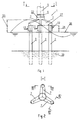
Figur 1 dargestellte Gründung für eine Offshore-Windkraftanlage umfaßt n=3 an den Ecken eines gedachten Vielecks in den Meeresboden 20 eingerammte Gründungsrohre 2 und eine einen Turm 5 der Offshore-Windkraftanlage tragende Stützstruktur 1, die über jeweils an ihren n=3 Ecken angeordnete steife Verbindungen 12 mit den freien Enden der Gründungsrohre 2 verbunden ist. - Die in der
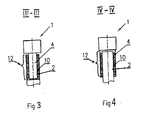
Figur 1 gezeigte Stützstruktur 1 umfaßt n=3 Radialstreben 7 mit sich radial nach außen verjüngendem rechteckigem Querschnitt, so daß sich jeweils ein verjüngendes Kastenrohr ergibt. Zentral in der Stützstruktur 1 ist ein Turnaufnahmeelement 22 mit zylindrisch-konischer Gestalt sowie einer Verbindung 6 angeordnet. Das Turmaufnahmeelement 22 ist mit den Radialstreben 7 fest verbunden. - Die freien Enden der Gründungsrohre 2 sind mit dem Stützgerüst steif verbunden. In den
Figuren 3 und 4 sind Beispiele für derartige steife Verbindungen, und zwar nach dem Rohrim-Rohr-Prinzip, dargestellt. InFigur 3 umfassen die steifen Verbindungen 12 Stutzen 4, die in die freien Enden der Gründungsrohre 2 mit Spiel, das heißt mit einem Hohlraum gesteckt sind. Damit die Verbindungen zwischen den Gründungsrohren 2 und den Stutzen 4 fest, steif und belastbar sind, wird der Hohlraum zum Beispiel mit Beton 10 vergossen. - In
Figur 4 umfassend die Verbindungen 12 Stutzen 4, die auf die freien Enden der Gründungsrohre 2 mit Spiel, das heißt mit einem Hohlraum gesteckt sind. Der Hohlraum wird wiederum zum Beispiel mit Beton 10 vergossen. - Selbstverständlich können die Verbindungen 12 an allen Ecken identisch sein, das heißt anders als in
Figur 2 gezeigt. - Eine steife Verbindung zwischen der Stützstruktur 1 und den Gründungsrohren 2 erhöht die Festigkeit der Gründung mit einer darauf befestigten Windkraftanlage, von der nur der Turm 5 - und auch nur teilweise - gezeigt ist, womit das Erreichen einer oberhalb eines erforderlichen Minimalwertes liegenden ersten Eigenfrequenz der Gründung vereinfacht wird.
- Das Anordnen der Stützstruktur 1 mit deren Unterseite 27 unterhalb des zu erwartenden Wellengangs 25, der der zu erwartenden maximalen Wellenhöhe entspricht, jedoch oberhalb des Meeresspiegels 26 erlaubt es, die Höhe, in der der Turm 5 mit der Stützstruktur 1 verbunden wird, zu verringern und auch die Windkraftanlage niedriger anzubringen. Dadurch wird das Erreichen der erforderlichen (höheren) Eigenfrequenz zusätzlich vereinfacht. Günstigerweise wird die Stützstruktur 1 - wie in den
Figuren 1 und3 gezeigt - oberhalb der Splash-Zone (Spritzwasserzone) 24 angebracht, da die Splash-Zone 24 durch erhöhte Korrosion der Konstruktion gekennzeichnet ist. - Die Ausführung des Stützgerüstes 1 mit Radialstreben 7 erlaubt es, die Höhe der Stützstruktur und somit der Verbindung zwischen der Stützstruktur 1 und dem Turm 5 zu verringern sowie die Windkraftanlage abzusenken.
- Die in der vorliegenden Beschreibung, in den Zeichnungen sowie in den Ansprüchen offenbarten Merkmale der Erfindung können sowohl einzeln als auch in beliebigen Kombinationen für die Verwirklichung der Erfindung in ihren verschiedenen Ausführungsformen wesentlich sein.
Claims (5)
- Gründung für eine Offshore-Windkraftanlage mit n an den Ecken eines gedachten regelmäßigen Vielecks in den Meeresboden (20) eingerammten Gründungsrohren (2) und mit einem den Turm (5) der Windkraftanlage tragenden n-eckigen Stützgerüst (1), das mit den freien Enden der Gründungsrohre (2) verbunden ist, wobei steife Verbindungen (12) zwischen dem Stützgerüst (1) und den freien Enden der Gründungsrohre (2) vorgesehen sind, und wobei das Stützgerüst (1) aus Radialstreben (7) mit nicht geschlitztem Profil besteht,
dadurch gekennzeichnet, dass
zumindest die Unterseite (27) des Stützgerüstes (1) unterhalb des zu erwartenden Wellengangs (25), jedoch über dem Meeresspiegel (26) angeordnet ist, die Radialstreben (7) einen sich radial nach außen ändernden Querschnitt aufweisen und dass die Verbindungen (12) zwischen den freien Enden der Gründungsrohre (2) und dem Stützgerüst (1) Stutzen (4) umfassen, die fest und steif mit dem Stützgerüst (1) verbunden sind und die in die freien Enden der Gründungsrohre (2) mit einem Hohlraum zwischen den Wänden der Gründungsrohre (2) und den Stutzen (4) gesteckt sind oder die auf die freien Enden der Gründungsrohre (2) von außen mit einem Hohlraum zwischen den Wänden der Stutzen (4) und den Gründungsrohren (2) gesteckt sind, wobei der Hohlraum vergossen ist. - Gründung nach Anspruch 1, dadurch gekennzeichnet, dass n=3 ist.
- Gründung nach Anspruch 1, dadurch gekennzeichnet, dass n=4 ist.
- Gründung nach einem der vorangehenden Ansprüche, dadurch gekennzeichnet, dass in dem Stützgerüst (1) ein aufrecht angeordnetes Turmaufnahmeelement (22) mit zylindrisch-konischer Gestalt und einer Verbindung (6) für den Turm (5) zentral angeordnet ist, welches durch die Radialstreben (7) mit den Stutzen (4) fest verbunden ist.
- Gründung nach einem der vorangehenden Ansprüche, dadurch gekennzeichnet, dass das Stützgerüst (1) ganz oder teilweise oberhalb der Splash-Zone (24) angeordnet ist.
Applications Claiming Priority (1)
| Application Number | Priority Date | Filing Date | Title |
|---|---|---|---|
| PCT/DE2004/001924 WO2006024244A1 (de) | 2004-08-31 | 2004-08-31 | Gründung für eine offshore-windkraftanlage |
Publications (2)
| Publication Number | Publication Date |
|---|---|
| EP1805414A1 EP1805414A1 (de) | 2007-07-11 |
| EP1805414B1 true EP1805414B1 (de) | 2015-12-09 |
Family
ID=34958956
Family Applications (1)
| Application Number | Title | Priority Date | Filing Date |
|---|---|---|---|
| EP04786200.8A Expired - Lifetime EP1805414B1 (de) | 2004-08-31 | 2004-08-31 | Gründung für eine offshore-windkraftanlage |
Country Status (3)
| Country | Link |
|---|---|
| EP (1) | EP1805414B1 (de) |
| DE (1) | DE112004003013A5 (de) |
| WO (1) | WO2006024244A1 (de) |
Cited By (2)
| Publication number | Priority date | Publication date | Assignee | Title |
|---|---|---|---|---|
| WO2019074363A1 (en) | 2017-10-10 | 2019-04-18 | Spt Equipment Bv | WIND ENERGY INSTALLATION FOUNDATION SYSTEM ON HIGH SEAS |
| NL2028088A (en) | 2020-04-29 | 2021-11-02 | Spt Equipment Bv | Concrete connector body for an offshore wind turbine. |
Families Citing this family (9)
| Publication number | Priority date | Publication date | Assignee | Title |
|---|---|---|---|---|
| DK2185816T3 (en) | 2007-08-29 | 2018-03-12 | Mhi Vestas Offshore Wind As | MONOPILE FOUNDATION FOR OFFSHORE WINDMILL |
| NO330373B1 (no) * | 2009-08-31 | 2011-04-04 | Aker Jacket Technology As | Lastoverforingsinnretning |
| DE102012006180A1 (de) | 2012-03-27 | 2013-10-02 | EcoEnterprises GmbH | Flexible Vorrichtung und Verfahren zur Herstellung von Großbauteilen im Stahlbau |
| EP3491240A1 (de) * | 2016-09-09 | 2019-06-05 | Siemens Gamesa Renewable Energy A/S | Übergangsstück für eine windturbine |
| GB201616488D0 (en) | 2016-09-28 | 2016-11-09 | Cps22 Limited | Apparatus |
| GB2561259B (en) | 2017-06-21 | 2019-05-08 | C Ling Ltd | Pull-in head assembly |
| GB2561261B (en) | 2017-06-21 | 2019-05-08 | C Ling Ltd | Pull-in head assembly |
| GB2561260B (en) | 2017-06-21 | 2019-05-08 | C Ling Ltd | Pull-in head assembly |
| WO2019043272A1 (es) * | 2017-08-29 | 2019-03-07 | Nabrawind Technologies, Sl | Conexión de torre tubular con celosia |
Family Cites Families (6)
| Publication number | Priority date | Publication date | Assignee | Title |
|---|---|---|---|---|
| US5567086A (en) * | 1994-12-23 | 1996-10-22 | Shell Oil Company | Tension leg caisson and method of erecting the same |
| DE19648299A1 (de) * | 1996-11-21 | 1997-11-20 | Siemens Ag | Mastkonstruktion |
| EP1074663A1 (de) * | 1999-08-06 | 2001-02-07 | Carl Bro as | Fundament für Gebäude, insbesondere Fundament für einen Turm, Windenergieanlage oder dergleichen |
| DE10061916B4 (de) * | 2000-12-18 | 2007-03-08 | Conrad Hansen | Gründung für eine Offshore-Windkraftanlage |
| DE20109981U1 (de) * | 2001-06-16 | 2001-10-04 | Hansen, Conrad, 24340 Eckernförde | Gründung für eine Offshore-Windkraftanlage |
| DE20210407U1 (de) * | 2002-07-05 | 2003-11-13 | GEO Gesellschaft für Energie und Ökologie mbH, 25917 Enge-Sande | Fahrzeug zur Versorgung von Offshore-Windenergieanlagen |
-
2004
- 2004-08-31 EP EP04786200.8A patent/EP1805414B1/de not_active Expired - Lifetime
- 2004-08-31 WO PCT/DE2004/001924 patent/WO2006024244A1/de active Application Filing
- 2004-08-31 DE DE112004003013T patent/DE112004003013A5/de not_active Withdrawn
Cited By (4)
| Publication number | Priority date | Publication date | Assignee | Title |
|---|---|---|---|---|
| WO2019074363A1 (en) | 2017-10-10 | 2019-04-18 | Spt Equipment Bv | WIND ENERGY INSTALLATION FOUNDATION SYSTEM ON HIGH SEAS |
| US12110862B2 (en) | 2017-10-10 | 2024-10-08 | Spt Equipment B.V. | Off shore wind energy installation foundation system |
| NL2028088A (en) | 2020-04-29 | 2021-11-02 | Spt Equipment Bv | Concrete connector body for an offshore wind turbine. |
| WO2021221506A1 (en) | 2020-04-29 | 2021-11-04 | Spt Equipment Bv | Offshore wind turbine foundation |
Also Published As
| Publication number | Publication date |
|---|---|
| DE112004003013A5 (de) | 2007-08-23 |
| EP1805414A1 (de) | 2007-07-11 |
| WO2006024244A1 (de) | 2006-03-09 |
Similar Documents
| Publication | Publication Date | Title |
|---|---|---|
| EP2737143B1 (de) | Vorrichtung zur verankerung von aufbauten im erdboden | |
| DE102004042066B4 (de) | Gründung für eine Offshore-Windkraftanlage | |
| EP2574711B2 (de) | Turm für eine Windenergieanlage | |
| EP2522780B1 (de) | Offshore-Fundament für Windenergieanlagen | |
| DE10349109B4 (de) | Gründung für eine Offshore-Windenergieanlage | |
| DE102016110290B4 (de) | Schwimmende Windenergieanlage mit einer Mehrzahl von Energiewandlungseinheiten | |
| WO2004101898A2 (de) | Fundament für eine windenergieanlage | |
| EP1805414B1 (de) | Gründung für eine offshore-windkraftanlage | |
| EP2828436B1 (de) | Offshore-fundament für windenergieanlagen mit bogenförmig gekrümmten knoten | |
| EP3208405B1 (de) | Vorrichtung und verfahren zur errichtung von turmartigen bauwerken aus fertigteilelementen | |
| DE102018115358A1 (de) | Schwimmtragwerk für eine Windkraftanlage | |
| EP1399631B1 (de) | Meerestechnische tragkonstruktion, insbesondere für eine offshore-windkraftanlage, und verfahren zur herstellung einer derartigen tragkonstruktionen | |
| DE102010012094B3 (de) | Gitterstruktur einer turmförmigen Gründung einer Offshore-Windenergieanlage sowie modulare Offshore-WEA-Gründung mit derselben | |
| DE202004020720U1 (de) | Gründung für eine Offshore-Windkraftanlage | |
| EP2561225B1 (de) | Standstruktur | |
| EP2839098B1 (de) | Gitterturm für windenergieanlagen und verfahren zur errichtung eines solchen gitterturmes | |
| EP2690221B1 (de) | Tragstruktur für Offshore-Anlagen | |
| DE10061916A1 (de) | Gründung für eine Offshore-Windkraftanlage | |
| DE102013015299B4 (de) | Jacket für eine Windkraftanlage und Verfahren zur Herstellung | |
| EP3597829B1 (de) | Gründungsverstärkung für offshore-bauwerke | |
| WO2013167101A2 (de) | Standstruktur | |
| EP2676031B1 (de) | Fundament für einen turm einer windkraftanlage | |
| WO2014124737A1 (de) | Schwerkraftfundament für ein offshore-bauwerk | |
| EP3056611B1 (de) | Kopplungsvorrichtung zum verbinden einer tragstruktur mit einem fundament im meeresboden | |
| DE102013113022A1 (de) | Gründung für eine Windkraftanlage |
Legal Events
| Date | Code | Title | Description |
|---|---|---|---|
| PUAI | Public reference made under article 153(3) epc to a published international application that has entered the european phase |
Free format text: ORIGINAL CODE: 0009012 |
|
| 17P | Request for examination filed |
Effective date: 20070516 |
|
| AK | Designated contracting states |
Kind code of ref document: A1 Designated state(s): AT BE BG CH CY CZ DE DK EE ES FI FR GB GR HU IE IT LI LU MC NL PL PT RO SE SI SK TR |
|
| DAX | Request for extension of the european patent (deleted) | ||
| 17Q | First examination report despatched |
Effective date: 20080905 |
|
| RAP1 | Party data changed (applicant data changed or rights of an application transferred) |
Owner name: BARD HOLDING GMBH |
|
| GRAP | Despatch of communication of intention to grant a patent |
Free format text: ORIGINAL CODE: EPIDOSNIGR1 |
|
| INTG | Intention to grant announced |
Effective date: 20150323 |
|
| GRAS | Grant fee paid |
Free format text: ORIGINAL CODE: EPIDOSNIGR3 |
|
| GRAA | (expected) grant |
Free format text: ORIGINAL CODE: 0009210 |
|
| AK | Designated contracting states |
Kind code of ref document: B1 Designated state(s): AT BE BG CH CY CZ DE DK EE ES FI FR GB GR HU IE IT LI LU MC NL PL PT RO SE SI SK TR |
|
| REG | Reference to a national code |
Ref country code: GB Ref legal event code: FG4D Free format text: NOT ENGLISH |
|
| REG | Reference to a national code |
Ref country code: AT Ref legal event code: REF Ref document number: 764699 Country of ref document: AT Kind code of ref document: T Effective date: 20151215 Ref country code: CH Ref legal event code: EP |
|
| REG | Reference to a national code |
Ref country code: IE Ref legal event code: FG4D Free format text: LANGUAGE OF EP DOCUMENT: GERMAN |
|
| REG | Reference to a national code |
Ref country code: DE Ref legal event code: R096 Ref document number: 502004015084 Country of ref document: DE |
|
| REG | Reference to a national code |
Ref country code: NL Ref legal event code: MP Effective date: 20151209 |
|
| PG25 | Lapsed in a contracting state [announced via postgrant information from national office to epo] |
Ref country code: ES Free format text: LAPSE BECAUSE OF FAILURE TO SUBMIT A TRANSLATION OF THE DESCRIPTION OR TO PAY THE FEE WITHIN THE PRESCRIBED TIME-LIMIT Effective date: 20151209 |
|
| PG25 | Lapsed in a contracting state [announced via postgrant information from national office to epo] |
Ref country code: NL Free format text: LAPSE BECAUSE OF FAILURE TO SUBMIT A TRANSLATION OF THE DESCRIPTION OR TO PAY THE FEE WITHIN THE PRESCRIBED TIME-LIMIT Effective date: 20151209 Ref country code: SE Free format text: LAPSE BECAUSE OF FAILURE TO SUBMIT A TRANSLATION OF THE DESCRIPTION OR TO PAY THE FEE WITHIN THE PRESCRIBED TIME-LIMIT Effective date: 20151209 Ref country code: FI Free format text: LAPSE BECAUSE OF FAILURE TO SUBMIT A TRANSLATION OF THE DESCRIPTION OR TO PAY THE FEE WITHIN THE PRESCRIBED TIME-LIMIT Effective date: 20151209 Ref country code: GR Free format text: LAPSE BECAUSE OF FAILURE TO SUBMIT A TRANSLATION OF THE DESCRIPTION OR TO PAY THE FEE WITHIN THE PRESCRIBED TIME-LIMIT Effective date: 20160310 |
|
| RAP2 | Party data changed (patent owner data changed or rights of a patent transferred) |
Owner name: DONG ENERGY A/S |
|
| PG25 | Lapsed in a contracting state [announced via postgrant information from national office to epo] |
Ref country code: IT Free format text: LAPSE BECAUSE OF FAILURE TO SUBMIT A TRANSLATION OF THE DESCRIPTION OR TO PAY THE FEE WITHIN THE PRESCRIBED TIME-LIMIT Effective date: 20151209 Ref country code: CZ Free format text: LAPSE BECAUSE OF FAILURE TO SUBMIT A TRANSLATION OF THE DESCRIPTION OR TO PAY THE FEE WITHIN THE PRESCRIBED TIME-LIMIT Effective date: 20151209 |
|
| PG25 | Lapsed in a contracting state [announced via postgrant information from national office to epo] |
Ref country code: PT Free format text: LAPSE BECAUSE OF FAILURE TO SUBMIT A TRANSLATION OF THE DESCRIPTION OR TO PAY THE FEE WITHIN THE PRESCRIBED TIME-LIMIT Effective date: 20160411 Ref country code: EE Free format text: LAPSE BECAUSE OF FAILURE TO SUBMIT A TRANSLATION OF THE DESCRIPTION OR TO PAY THE FEE WITHIN THE PRESCRIBED TIME-LIMIT Effective date: 20151209 Ref country code: SK Free format text: LAPSE BECAUSE OF FAILURE TO SUBMIT A TRANSLATION OF THE DESCRIPTION OR TO PAY THE FEE WITHIN THE PRESCRIBED TIME-LIMIT Effective date: 20151209 Ref country code: RO Free format text: LAPSE BECAUSE OF FAILURE TO SUBMIT A TRANSLATION OF THE DESCRIPTION OR TO PAY THE FEE WITHIN THE PRESCRIBED TIME-LIMIT Effective date: 20151209 |
|
| REG | Reference to a national code |
Ref country code: DE Ref legal event code: R097 Ref document number: 502004015084 Country of ref document: DE |
|
| PLBE | No opposition filed within time limit |
Free format text: ORIGINAL CODE: 0009261 |
|
| STAA | Information on the status of an ep patent application or granted ep patent |
Free format text: STATUS: NO OPPOSITION FILED WITHIN TIME LIMIT |
|
| PG25 | Lapsed in a contracting state [announced via postgrant information from national office to epo] |
Ref country code: PL Free format text: LAPSE BECAUSE OF FAILURE TO SUBMIT A TRANSLATION OF THE DESCRIPTION OR TO PAY THE FEE WITHIN THE PRESCRIBED TIME-LIMIT Effective date: 20151209 Ref country code: DK Free format text: LAPSE BECAUSE OF FAILURE TO SUBMIT A TRANSLATION OF THE DESCRIPTION OR TO PAY THE FEE WITHIN THE PRESCRIBED TIME-LIMIT Effective date: 20151209 |
|
| PGFP | Annual fee paid to national office [announced via postgrant information from national office to epo] |
Ref country code: DE Payment date: 20160901 Year of fee payment: 13 |
|
| 26N | No opposition filed |
Effective date: 20160912 |
|
| PG25 | Lapsed in a contracting state [announced via postgrant information from national office to epo] |
Ref country code: SI Free format text: LAPSE BECAUSE OF FAILURE TO SUBMIT A TRANSLATION OF THE DESCRIPTION OR TO PAY THE FEE WITHIN THE PRESCRIBED TIME-LIMIT Effective date: 20151209 |
|
| PG25 | Lapsed in a contracting state [announced via postgrant information from national office to epo] |
Ref country code: BE Free format text: LAPSE BECAUSE OF NON-PAYMENT OF DUE FEES Effective date: 20160831 |
|
| PG25 | Lapsed in a contracting state [announced via postgrant information from national office to epo] |
Ref country code: MC Free format text: LAPSE BECAUSE OF FAILURE TO SUBMIT A TRANSLATION OF THE DESCRIPTION OR TO PAY THE FEE WITHIN THE PRESCRIBED TIME-LIMIT Effective date: 20151209 |
|
| REG | Reference to a national code |
Ref country code: CH Ref legal event code: PL |
|
| GBPC | Gb: european patent ceased through non-payment of renewal fee |
Effective date: 20160831 |
|
| PG25 | Lapsed in a contracting state [announced via postgrant information from national office to epo] |
Ref country code: LI Free format text: LAPSE BECAUSE OF NON-PAYMENT OF DUE FEES Effective date: 20160831 Ref country code: CH Free format text: LAPSE BECAUSE OF NON-PAYMENT OF DUE FEES Effective date: 20160831 |
|
| REG | Reference to a national code |
Ref country code: FR Ref legal event code: ST Effective date: 20170428 |
|
| REG | Reference to a national code |
Ref country code: IE Ref legal event code: MM4A |
|
| PG25 | Lapsed in a contracting state [announced via postgrant information from national office to epo] |
Ref country code: IE Free format text: LAPSE BECAUSE OF NON-PAYMENT OF DUE FEES Effective date: 20160831 Ref country code: GB Free format text: LAPSE BECAUSE OF NON-PAYMENT OF DUE FEES Effective date: 20160831 Ref country code: FR Free format text: LAPSE BECAUSE OF NON-PAYMENT OF DUE FEES Effective date: 20160831 |
|
| PG25 | Lapsed in a contracting state [announced via postgrant information from national office to epo] |
Ref country code: LU Free format text: LAPSE BECAUSE OF NON-PAYMENT OF DUE FEES Effective date: 20160831 |
|
| REG | Reference to a national code |
Ref country code: AT Ref legal event code: MM01 Ref document number: 764699 Country of ref document: AT Kind code of ref document: T Effective date: 20160831 |
|
| PG25 | Lapsed in a contracting state [announced via postgrant information from national office to epo] |
Ref country code: AT Free format text: LAPSE BECAUSE OF NON-PAYMENT OF DUE FEES Effective date: 20160831 |
|
| REG | Reference to a national code |
Ref country code: DE Ref legal event code: R119 Ref document number: 502004015084 Country of ref document: DE |
|
| PG25 | Lapsed in a contracting state [announced via postgrant information from national office to epo] |
Ref country code: HU Free format text: LAPSE BECAUSE OF FAILURE TO SUBMIT A TRANSLATION OF THE DESCRIPTION OR TO PAY THE FEE WITHIN THE PRESCRIBED TIME-LIMIT; INVALID AB INITIO Effective date: 20040831 Ref country code: CY Free format text: LAPSE BECAUSE OF FAILURE TO SUBMIT A TRANSLATION OF THE DESCRIPTION OR TO PAY THE FEE WITHIN THE PRESCRIBED TIME-LIMIT Effective date: 20151209 |
|
| PG25 | Lapsed in a contracting state [announced via postgrant information from national office to epo] |
Ref country code: TR Free format text: LAPSE BECAUSE OF FAILURE TO SUBMIT A TRANSLATION OF THE DESCRIPTION OR TO PAY THE FEE WITHIN THE PRESCRIBED TIME-LIMIT Effective date: 20151209 |
|
| PG25 | Lapsed in a contracting state [announced via postgrant information from national office to epo] |
Ref country code: DE Free format text: LAPSE BECAUSE OF NON-PAYMENT OF DUE FEES Effective date: 20180301 Ref country code: BG Free format text: LAPSE BECAUSE OF FAILURE TO SUBMIT A TRANSLATION OF THE DESCRIPTION OR TO PAY THE FEE WITHIN THE PRESCRIBED TIME-LIMIT Effective date: 20151209 |