EP1804312A2 - Connection structure between unit cells - Google Patents
Connection structure between unit cells Download PDFInfo
- Publication number
- EP1804312A2 EP1804312A2 EP06127238A EP06127238A EP1804312A2 EP 1804312 A2 EP1804312 A2 EP 1804312A2 EP 06127238 A EP06127238 A EP 06127238A EP 06127238 A EP06127238 A EP 06127238A EP 1804312 A2 EP1804312 A2 EP 1804312A2
- Authority
- EP
- European Patent Office
- Prior art keywords
- ring
- unit cells
- connection structure
- battery
- flange
- Prior art date
- Legal status (The legal status is an assumption and is not a legal conclusion. Google has not performed a legal analysis and makes no representation as to the accuracy of the status listed.)
- Withdrawn
Links
Images


Classifications
-
- H—ELECTRICITY
- H01—ELECTRIC ELEMENTS
- H01M—PROCESSES OR MEANS, e.g. BATTERIES, FOR THE DIRECT CONVERSION OF CHEMICAL ENERGY INTO ELECTRICAL ENERGY
- H01M50/00—Constructional details or processes of manufacture of the non-active parts of electrochemical cells other than fuel cells, e.g. hybrid cells
- H01M50/50—Current conducting connections for cells or batteries
-
- H—ELECTRICITY
- H01—ELECTRIC ELEMENTS
- H01M—PROCESSES OR MEANS, e.g. BATTERIES, FOR THE DIRECT CONVERSION OF CHEMICAL ENERGY INTO ELECTRICAL ENERGY
- H01M50/00—Constructional details or processes of manufacture of the non-active parts of electrochemical cells other than fuel cells, e.g. hybrid cells
- H01M50/10—Primary casings; Jackets or wrappings
- H01M50/147—Lids or covers
- H01M50/166—Lids or covers characterised by the methods of assembling casings with lids
- H01M50/171—Lids or covers characterised by the methods of assembling casings with lids using adhesives or sealing agents
-
- H—ELECTRICITY
- H01—ELECTRIC ELEMENTS
- H01M—PROCESSES OR MEANS, e.g. BATTERIES, FOR THE DIRECT CONVERSION OF CHEMICAL ENERGY INTO ELECTRICAL ENERGY
- H01M50/00—Constructional details or processes of manufacture of the non-active parts of electrochemical cells other than fuel cells, e.g. hybrid cells
- H01M50/10—Primary casings; Jackets or wrappings
- H01M50/102—Primary casings; Jackets or wrappings characterised by their shape or physical structure
- H01M50/107—Primary casings; Jackets or wrappings characterised by their shape or physical structure having curved cross-section, e.g. round or elliptic
-
- H—ELECTRICITY
- H01—ELECTRIC ELEMENTS
- H01M—PROCESSES OR MEANS, e.g. BATTERIES, FOR THE DIRECT CONVERSION OF CHEMICAL ENERGY INTO ELECTRICAL ENERGY
- H01M50/00—Constructional details or processes of manufacture of the non-active parts of electrochemical cells other than fuel cells, e.g. hybrid cells
- H01M50/20—Mountings; Secondary casings or frames; Racks, modules or packs; Suspension devices; Shock absorbers; Transport or carrying devices; Holders
-
- H—ELECTRICITY
- H01—ELECTRIC ELEMENTS
- H01M—PROCESSES OR MEANS, e.g. BATTERIES, FOR THE DIRECT CONVERSION OF CHEMICAL ENERGY INTO ELECTRICAL ENERGY
- H01M50/00—Constructional details or processes of manufacture of the non-active parts of electrochemical cells other than fuel cells, e.g. hybrid cells
- H01M50/30—Arrangements for facilitating escape of gases
-
- H—ELECTRICITY
- H01—ELECTRIC ELEMENTS
- H01M—PROCESSES OR MEANS, e.g. BATTERIES, FOR THE DIRECT CONVERSION OF CHEMICAL ENERGY INTO ELECTRICAL ENERGY
- H01M50/00—Constructional details or processes of manufacture of the non-active parts of electrochemical cells other than fuel cells, e.g. hybrid cells
- H01M50/50—Current conducting connections for cells or batteries
- H01M50/502—Interconnectors for connecting terminals of adjacent batteries; Interconnectors for connecting cells outside a battery casing
- H01M50/509—Interconnectors for connecting terminals of adjacent batteries; Interconnectors for connecting cells outside a battery casing characterised by the type of connection, e.g. mixed connections
- H01M50/51—Connection only in series
-
- H—ELECTRICITY
- H01—ELECTRIC ELEMENTS
- H01M—PROCESSES OR MEANS, e.g. BATTERIES, FOR THE DIRECT CONVERSION OF CHEMICAL ENERGY INTO ELECTRICAL ENERGY
- H01M50/00—Constructional details or processes of manufacture of the non-active parts of electrochemical cells other than fuel cells, e.g. hybrid cells
- H01M50/50—Current conducting connections for cells or batteries
- H01M50/502—Interconnectors for connecting terminals of adjacent batteries; Interconnectors for connecting cells outside a battery casing
- H01M50/514—Methods for interconnecting adjacent batteries or cells
- H01M50/516—Methods for interconnecting adjacent batteries or cells by welding, soldering or brazing
-
- H—ELECTRICITY
- H01—ELECTRIC ELEMENTS
- H01M—PROCESSES OR MEANS, e.g. BATTERIES, FOR THE DIRECT CONVERSION OF CHEMICAL ENERGY INTO ELECTRICAL ENERGY
- H01M50/00—Constructional details or processes of manufacture of the non-active parts of electrochemical cells other than fuel cells, e.g. hybrid cells
- H01M50/50—Current conducting connections for cells or batteries
- H01M50/502—Interconnectors for connecting terminals of adjacent batteries; Interconnectors for connecting cells outside a battery casing
- H01M50/514—Methods for interconnecting adjacent batteries or cells
- H01M50/517—Methods for interconnecting adjacent batteries or cells by fixing means, e.g. screws, rivets or bolts
-
- H—ELECTRICITY
- H01—ELECTRIC ELEMENTS
- H01M—PROCESSES OR MEANS, e.g. BATTERIES, FOR THE DIRECT CONVERSION OF CHEMICAL ENERGY INTO ELECTRICAL ENERGY
- H01M50/00—Constructional details or processes of manufacture of the non-active parts of electrochemical cells other than fuel cells, e.g. hybrid cells
- H01M50/50—Current conducting connections for cells or batteries
- H01M50/543—Terminals
-
- Y—GENERAL TAGGING OF NEW TECHNOLOGICAL DEVELOPMENTS; GENERAL TAGGING OF CROSS-SECTIONAL TECHNOLOGIES SPANNING OVER SEVERAL SECTIONS OF THE IPC; TECHNICAL SUBJECTS COVERED BY FORMER USPC CROSS-REFERENCE ART COLLECTIONS [XRACs] AND DIGESTS
- Y02—TECHNOLOGIES OR APPLICATIONS FOR MITIGATION OR ADAPTATION AGAINST CLIMATE CHANGE
- Y02E—REDUCTION OF GREENHOUSE GAS [GHG] EMISSIONS, RELATED TO ENERGY GENERATION, TRANSMISSION OR DISTRIBUTION
- Y02E60/00—Enabling technologies; Technologies with a potential or indirect contribution to GHG emissions mitigation
- Y02E60/10—Energy storage using batteries
-
- Y—GENERAL TAGGING OF NEW TECHNOLOGICAL DEVELOPMENTS; GENERAL TAGGING OF CROSS-SECTIONAL TECHNOLOGIES SPANNING OVER SEVERAL SECTIONS OF THE IPC; TECHNICAL SUBJECTS COVERED BY FORMER USPC CROSS-REFERENCE ART COLLECTIONS [XRACs] AND DIGESTS
- Y02—TECHNOLOGIES OR APPLICATIONS FOR MITIGATION OR ADAPTATION AGAINST CLIMATE CHANGE
- Y02P—CLIMATE CHANGE MITIGATION TECHNOLOGIES IN THE PRODUCTION OR PROCESSING OF GOODS
- Y02P70/00—Climate change mitigation technologies in the production process for final industrial or consumer products
- Y02P70/50—Manufacturing or production processes characterised by the final manufactured product
-
- Y—GENERAL TAGGING OF NEW TECHNOLOGICAL DEVELOPMENTS; GENERAL TAGGING OF CROSS-SECTIONAL TECHNOLOGIES SPANNING OVER SEVERAL SECTIONS OF THE IPC; TECHNICAL SUBJECTS COVERED BY FORMER USPC CROSS-REFERENCE ART COLLECTIONS [XRACs] AND DIGESTS
- Y10—TECHNICAL SUBJECTS COVERED BY FORMER USPC
- Y10T—TECHNICAL SUBJECTS COVERED BY FORMER US CLASSIFICATION
- Y10T29/00—Metal working
- Y10T29/49—Method of mechanical manufacture
- Y10T29/49002—Electrical device making
- Y10T29/49108—Electric battery cell making
Definitions
- the present invention relates to the connection structure which composes module batteries in which a plurality of cylindrical batteries are connected in series, and in particular, the present invention relates to the connection structure between unit cells in which electrical resistance between unit cells are greatly reduced and mechanical strength is improved.
- a metal case also acts as a negative terminal of the battery, and an aperture portion of the metal case is sealed by a sealing plate (or cap) which is a positive electrode terminal interposing an electrically insulating resin gasket therebetween.
- a sealing plate or cap
- the method of connecting the positive terminal of one unit cell and the negative terminal of another unit cell by spot welding interposing a connection body of a metal plate therebetween has been used up to the present.
- Patent document 1 Japanese Patent Laid-Open Publications No. Hei 10-106533 (Patent document 1) and No. 2000-149907 (Patent document 2) disclose projection welding method. Both methods provide projections at portions contacting in a plane thereby intensively loading welding current.
- the increased welding current causes the heat at the welding portion to rise, and the temperature in the batteries inevitably rises due to thermal conduction.
- the temperature rise in the batteries occurs, deformation of a rubber valve which releases gas outside when the in the internal gas pressure in the batteries abnormally rises or deformation of a gasket which tightly closes the batteries from outside occurs. Since these things become the causes for lowering the electrical characteristics, there is a limit of merely increasing welding current for the purpose of the firm welding.
- connection structure capable of greatly reducing the electrical resistance is required as a result of firm welding without badly affecting said electrical characteristics accompanying temperature rise at the time of welding nevertheless, capable of welding with a connection body for connecting unit cells, in particular, with a thick material with decreased electrical resistance.
- the present invention relates to a connection structure between unit cells connecting a plurality of batteries in series with bottomed cylindrical battery cases which function as electrode terminals on one side, sealing plates which close the opening portions of the battery cases which function as electrode terminals on another side, wherein the first ring made of a metal having a flange is jointed at a bottom portion of a battery case of one battery in a conductive manner, the second ring made of a metal having a flange is jointed at an upper portion of a sealing plate of another battery in a conductive manner, and said first ring made of a metal and said second ring made of a metal are fitted.
- the present invention also relates to a connection structure between unit cells connecting a plurality of batteries in series with bottomed cylindrical battery cases which function as electrode terminals on one side, sealing plates which close the opening portions of the battery cases which function as electrode terminals on another side, wherein the first ring made of a metal having a flange is jointed at a bottom portion of a battery case of one battery in a conductive manner, the second ring made of a metal having a flange is jointed at an upper portion of a sealing plate of another battery in a conductive manner, and a screw groove is formed in an outer side surface of a cylindrical portion of one of said first ring made of a metal and said second ring made of a metal and an inner side surface of a cylindrical portion of another of said first ring made of a metal and said second ring made of a metal, and said first and said second rings made of a metal are screw fitted.
- the present invention relates to the connection structure between unit cells, wherein a ventilating groove which ventilates to atmospheric air is provided on a jointed surface of at least one flange of said first ring made of a metal and said second ring made of a metal.
- connection structure between the unit cells of the present invention a sealing plate is enclosed by the ring made of a metal.
- a connecting groove connective to atmospheric air on a jointed surface of a flange inside of the ring, even when the inner pressure rises, the pressure can be relieved.
- the present invention relates to the connection structure between unit cells, wherein said first ring made of a metal and said second ring made of a metal are welded and the welding means laser welding here. Further, the present invention relates to the connection structure between unit cells, wherein a distance between a flange of said first ring made of a metal and a flange of said second ring made of a metal is not less than 3 mm, fixture is available at more than two portions between connected unit cells, and an insulating resin fixing frame for air flow is provided.
- laser welding is available which has little thermal conduction to the surroundings for the purpose of increasing mechanical strength and reducing electrical resistance at a connecting portion after fixing the ring made of a metal by fitting or screw fitting.
- connection structure between unit cells according to the present invention can elongate the distance of adjacent batteries since larger mechanical strength can be obtained by the latter structure. As a result, radiation effect between unit cells can be expected thereby inhibiting the temperature rise which is a cause of lowering the battery characteristics.
- the present invention relates to a manufacturing method of unit cells, comprising of jointing the first ring made of a metal having a flange to a bottom portion of a battery case of one battery in a conductive manner, and/or jointing the second ring made of a metal having a flange to an upper portion of a sealing plate of another battery in a conductive manner, and inserting generating element which includes electrodes, a separator, an electrolyte, connecting said electrodes to said battery case and said sealing plate electrically and closing the opening portion of said battery case with said sealing plate.
- unit cells are connected electrically in a state of sealing batteries after inserting generating element in a battery case.
- the ring made of a metal having a flange is welded to the bottomed cylindrical case or to the sealing plate before inserting an electrode and a separator which is generating element in a bottomed cylindrical case.
- the present invention has a structure of connecting unit cells with a ring made of a metal having a flange and compared with conventional connection structures, even when the distance between unit cells is elongated, the electrical resistance at a connecting portion does not increase.
- This structure allows to employ a welding method such as laser welding with high output density without contacting with a welding portion in welding between unit cells. Further, since welding with high output density is available, welding strength can be improved and welded portions can be concentrated, thereby capable of inhibiting the temperature rise around the welding portion.
- Fig.1 is a schematic cross-sectional view showing a state prior to the connection of the connection structure between unit cells of the present invention.
- the first ring made of a metal 1a having a flange is jointed at the bottom surface of a bottomed cylindrical case 2 together in a conductive manner beforehand.
- the second ring made of a metal 1b having a flange is jointed in the upper portion of the sealing plate 3 together in a conductive manner beforehand.
- Junction is preferably made for example, by welding.
- the sealing plate 3 and the second ring made of a metal 1b jointed together and integrated tightly close the battery interposing a gasket 4 therebetween.
- an inner diameter of the first ring made of a metal 1a and an outer diameter of the second ring made of a metal 1b are designed to have substantially the same size. Designed as such, the first ring made of a metal 1a and the second ring made of a metal 1b can be fitted with no space therebetween. Composed as such, a unit cell B1 and a unit cell B2 can be connected electrically and mechanically.
- metal foil for fitting in the gap between the first ring made of a metal 1a and the second ring made of a metal 1 b, electrical resistance can further be inhibited.
- Materials for metal foils are preferably aluminum (Al), copper (Cu), nickel (Ni), or alloys whose main materials are aluminum (Al), copper (Cu), and nickel (Ni).
- the present invention enables the application of laser welding or arc welding, a structure which can enhance contact strength can be realized.
- lowering in the electrical resistance by 0.2 to 0.3 m ⁇ which is an actual measurement value was acknowledged.
- the current sometimes reaches as high as 150 A, though instantaneously.
- the lowering of battery voltage by 30 to 45 mV can be calculated from said electrical resistance value, and therefore, lowering the electrical resistance at the connecting portion as disclosed in the present invention becomes the important factor for the batteries for hybrid electric vehicles.
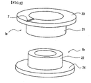
- Fig.2 shows the oblique view showing the first ring made of a metal 1a and the second ring made of a metal 1b and it was made clear that the fitting portion should have a cylindrical shape and its thickness should be not less than 1.5 mm considering the strength and the electrical resistance when fitted, and desirably, 2 to 3 mm, and that the lower limit of the thickness should be within the aforementioned range. Increasing the lower limit over the aforementioned range further improves strength and electrical resistance, however, the battery weight increases and high output is required for welding the fitting portion mentioned later and considering the bad effect caused by the temperature rise at the time of welding, as thickness of cylindrical portion, said designated range is appropriate.
- the length should be at least 3 mm. Therefore, it can be acknowledged that the pipe portion of the flange connection body inevitably has the length of not less than 3mm. However, to unnecessarily elongate the length causes the increase in electrical resistance at the connecting portion, and therefore, there is a reasonable upper limit. By this structure, the heating of the battery mentioned later can be inhibited.
- the thickness of flanges 23 and 24 of rings made of metal 1a and 1b which directly contact with the bottomed cylindrical battery case 2 which is also one electrode terminal or the sealing plate 3 which is also another electrode terminal at the time of integration by a spot welding is found to be effective for improvement in welding strength when said thickness is around 0.5 mm. Since this thickness is substantially the same as that of the material which composes a bottomed cylindrical battery case 2 and the sealing plate 3, it is desirable that the thickness of the flanges 23 and 24 is set to be substantially the same as that of the welded portion for securing the welding strength. Therefore, since the optimum value varies depending on the parts which compose the battery, the thickness of flanges 23 and 24 should be set based on the thickness of the bottomed cylindrical battery case 2 and the sealing plate 3.
- welding is available not only by the spot welding but also by the socalled inverter welding method using an inverter DC power source.
- stronger welding is available since structure of intensively applying a current to the protruded portion provided on the same radius of the welded surface of flanges 23 and 24 becomes available.
- the first ring made of a metal 1a can be directly welded in a bottomed cylindrical case 2 in the step before a power generating element and electrolyte are contained in the battery case 2.
- the second ring made of a metal 1b can be welded in a sealing plate 3.
- the welding part can be made firm.
- a ventilating groove 7 is hereby explained.
- a rubber valve 6 shown in Fig.1 is internally fitted in the sealing plate 3.
- the rubber valve 6 is deformed and the gas is exhausted from the inside.
- the ventilating groove 7 which can exhaust the gas outside is formed at least on one jointed surface of flanges 23 and 24.
- the present invention by thickening the thickness of the cylindrical portions 21 and 22 of the first ring made of a metal 1a and the second ring made of a metal 1b, electrical resistance can be lowered. As a result, in the fitted state as shown in Fig.3, even when the distance A between flanges 23 and 24 is elongated, the ratio of the increase in electrical resistance becomes less. From this, as mentioned above, the laser welding is applicable to the fitting portion and further, since the structure in which at least one portion of the first ring made of a metal 1a and the second ring made of a metal 1b can be exposed is available, function with excellent heat radiation performance can be added.
- the fixing frame 18 is provided with the supporting portion 18a which can support on two portions or more thereby enabling welding of jointed portions or screw fitting portions and ventilating air.
- a screw groove (female screw) 8 is formed inside of a cylindrical portion of the first ring made of a metal 1a and a screw groove (male screw) 9 corresponding to the outside of a cylindrical portion of the second ring made of a metal 1b, thereby connecting the first ring made of a metal 1a and the second ring made of a metal 1b with a screw fitting as shown in Fig.4.
- a ventilating pore 17 is preferably provided on the second connector made of a metal 1 d to be fitted and screw fitted in the side with a sealing plate 3.
- Batteries to be measured are D sized batteries (cylindrical sealed batteries with an outer diameter of 17 mm and a height of 56 mm by the single size).
- the first ring made of a metal 1a was welded to a sealing plate 3 which is a positive electrode terminal.
- the thickness of a flange 23 of the first ring made of a metal 1a used here was 0.5 mm, and the outer diameter was 23 mm, the outer diameter of a cylindrical portion 21 was 17 mm, and the inner diameter was 13.8 mm.
- the second ring made of a metal 1b was welded to a bottom portion of a battery case 2 which is a negative electrode terminal.
- the thickness of a flange 24 of the second ring made of a metal 1b was 0.5 mm, and the outer diameter was 20 mm, and the outer diameter of a cylindrical portion 22 was 13.7 mm, and the inner diameter of was 10 mm.
- a connection system, the presence or absence of copper foils and of laser welding are as shown in the table 1.
- a metal foil used for lowering the electrical resistance of a fitting portion and a screw fitting portion a copper foil with a thickness of 20 ⁇ m was used.
- a laser welder manufactured by MIYACHI CORPORATION: type ML-2550A
- irradiation was applied for 0.1 second with an irradiating diameter of 0.6mm and with an output of 5.4kW.
- a female screw of M16 When connected by screw fitting, a female screw of M16 is formed in an inner side surface of a cylindrical portion of the first ring made of a metal 1a and a male screw of M16 is formed in an outer side surface of a cylindrical portion of the second ring made of a metal 1b.
- Table 1 Result of measurement of electrical resistance of a connection method and of a connection portion Connection system The presence of copper foil at a connecting portion Laser welding Electrical resistance at the connecting portion (m ⁇ ) Yes or No Number of laser points Fitting method Present Not present No -- 1.31 -- 0.81 Not present Yes 4 0.56 6 0.51 8 0.49 Screw fitting method Not present Present No -- 1.55 -- 0.82 Not present Yes 4 0.58 6 0.52 8 0.50
- the value of resistance when simply fitted or screw fitted was 1.31 to 1.55 m ⁇ . This value has no bad effect from the practical view point judging from that the voltage decreases by 65.5 to 77.5 mV when 50 A of current is applied by a nickel cadmium battery or nickel hydroxide battery practically used as a battery for large current and that the operation voltage of the battery is 1.2 V, the voltage decreases by more than 5 %.
Landscapes
- Chemical & Material Sciences (AREA)
- Chemical Kinetics & Catalysis (AREA)
- Electrochemistry (AREA)
- General Chemical & Material Sciences (AREA)
- Connection Of Batteries Or Terminals (AREA)
Abstract
Description
- The description of this application claims benefit of priority based on
Japanese Patent Application No.2005-375324 - The present invention relates to the connection structure which composes module batteries in which a plurality of cylindrical batteries are connected in series, and in particular, the present invention relates to the connection structure between unit cells in which electrical resistance between unit cells are greatly reduced and mechanical strength is improved.
- From the past, in forming storage battery modules for obtaining desired output voltage by connecting a plurality of unit cells in series, metal foil junctions for connecting between unit cells have been used. In generally used batteries, a metal case also acts as a negative terminal of the battery, and an aperture portion of the metal case is sealed by a sealing plate (or cap) which is a positive electrode terminal interposing an electrically insulating resin gasket therebetween. As a way to electrically connecting the two unit cells, the method of connecting the positive terminal of one unit cell and the negative terminal of another unit cell by spot welding interposing a connection body of a metal plate therebetween has been used up to the present.
- Spot welding can easily be conducted when two metal plates are connected in thickness direction. However, when the aforementioned unit cells are welded, in principal, welding in thickness direction becomes difficult since a metal plate and a battery terminal of an opposite end is electrically insulated. Therefore, such a welding method has been employed in which a welding current is applied bringing two welding rods closer and heating the metal plate until it is fused, thereby welding the metal plate to the battery terminal. With this method, temperature must be risen to weld the metal plate, and when thickness of the metal plate connected is thick, it is very difficult to surely weld the metal plate and even when the metal plate should be welded, due to welding current, the temperature rise in unit cells becomes great, causing deterioration in electrical characteristics.
- This method is widely used since less heat is generated and welding can be easily conducted, and no problem occurs when relatively little current is used in the limited case where a connector is made of a thin plate (not greater than about 300µm thick). However, for the use where large current discharge is desired the problem of which lies in the electrical resistance between unit cells, when the afore mentioned spot welding method is employed, the distance between welded spots becomes large and as a result of increased electrical resistance, decrease in discharge voltage and in output characteristics are caused. Further, since mechanical strength at the connecting portion is weak, for the automobile use the problem of which lies in vibrations, some measures need to be taken for improving the mechanical strength.
- From such backgrounds, batteries in Japanese Patent Laid-Open Publications
No. Hei 10-106533 No. 2000-149907 - Both of
patent documents 1 and 2 disclose methods of welding between unit cells after completing the unit cells. In order to lower the electrical resistance and improve the mechanical strength, firm welding of a connection body is required by increasing the welding current. Further, there still remains a problem that unless the positions to which a current is applied have substantially the same thickness, firm welding cannot be made in the case where a connection body which is required for connecting unit cells and the sealing plates of the unit cells are welded or in the case where the battery case and the connection body are welded. In other words, by making welded portions of a sealing plate of a battery, welded portions of a battery case and welded portion of the connection body have substantially the same thickness, firm welding is available. Therefore, there lies a problem of inability for firm welding when a thick material with reduced electrical resistance is used only for the connection body. - Further, although improving the firm welding by increasing the welding current is easily assumed, the increased welding current causes the heat at the welding portion to rise, and the temperature in the batteries inevitably rises due to thermal conduction. When the temperature rise in the batteries occurs, deformation of a rubber valve which releases gas outside when the in the internal gas pressure in the batteries abnormally rises or deformation of a gasket which tightly closes the batteries from outside occurs. Since these things become the causes for lowering the electrical characteristics, there is a limit of merely increasing welding current for the purpose of the firm welding.
- Therefore, the present invention has found that such a connection structure capable of greatly reducing the electrical resistance is required as a result of firm welding without badly affecting said electrical characteristics accompanying temperature rise at the time of welding nevertheless, capable of welding with a connection body for connecting unit cells, in particular, with a thick material with decreased electrical resistance.
- In addition, since such kinds of batteries require large-current in charging and discharging, the temperature rise during the operation becomes great. In considering the heat resistance or electrical characteristics of the materials generally used for batteries, battery temperature is desirably set in the vicinity of a room temperature, therefore, when the heat reaches high temperature, some cooling methods are required to take. However, since one of the prior arts Patent document 1 employs the method of shortening the distance between unit cells as much as possible in order to lower the electrical resistance between the unit cells, another structure by which discharge effect from the connecting unit cells can be expected is required.
- The present invention relates to a connection structure between unit cells connecting a plurality of batteries in series with bottomed cylindrical battery cases which function as electrode terminals on one side, sealing plates which close the opening portions of the battery cases which function as electrode terminals on another side, wherein the first ring made of a metal having a flange is jointed at a bottom portion of a battery case of one battery in a conductive manner, the second ring made of a metal having a flange is jointed at an upper portion of a sealing plate of another battery in a conductive manner, and said first ring made of a metal and said second ring made of a metal are fitted.
- The present invention also relates to a connection structure between unit cells connecting a plurality of batteries in series with bottomed cylindrical battery cases which function as electrode terminals on one side, sealing plates which close the opening portions of the battery cases which function as electrode terminals on another side, wherein the first ring made of a metal having a flange is jointed at a bottom portion of a battery case of one battery in a conductive manner, the second ring made of a metal having a flange is jointed at an upper portion of a sealing plate of another battery in a conductive manner, and a screw groove is formed in an outer side surface of a cylindrical portion of one of said first ring made of a metal and said second ring made of a metal and an inner side surface of a cylindrical portion of another of said first ring made of a metal and said second ring made of a metal, and said first and said second rings made of a metal are screw fitted.
- At the time of welding the ring made of a metal for connecting unit cells, temperature rise is accompanied, however, before manufacturing the battery, the ring made of a metal is welded to a battery case and a sealing plate. As a result, a method of firm welding can be provided without causing any bad effect on said battery characteristics as mentioned above.
- The present invention relates to the connection structure between unit cells, wherein a ventilating groove which ventilates to atmospheric air is provided on a jointed surface of at least one flange of said first ring made of a metal and said second ring made of a metal.
- In the connection structure between the unit cells of the present invention, a sealing plate is enclosed by the ring made of a metal. However, by providing a connecting groove connective to atmospheric air on a jointed surface of a flange inside of the ring, even when the inner pressure rises, the pressure can be relieved.
- The present invention relates to the connection structure between unit cells, wherein said first ring made of a metal and said second ring made of a metal are welded and the welding means laser welding here. Further, the present invention relates to the connection structure between unit cells, wherein a distance between a flange of said first ring made of a metal and a flange of said second ring made of a metal is not less than 3 mm, fixture is available at more than two portions between connected unit cells, and an insulating resin fixing frame for air flow is provided.
- Further, in the structure of the present invention, laser welding is available which has little thermal conduction to the surroundings for the purpose of increasing mechanical strength and reducing electrical resistance at a connecting portion after fixing the ring made of a metal by fitting or screw fitting.
- Compared with a conventional connection structure, the connection structure between unit cells according to the present invention can elongate the distance of adjacent batteries since larger mechanical strength can be obtained by the latter structure. As a result, radiation effect between unit cells can be expected thereby inhibiting the temperature rise which is a cause of lowering the battery characteristics.
- The present invention relates to a manufacturing method of unit cells, comprising of jointing the first ring made of a metal having a flange to a bottom portion of a battery case of one battery in a conductive manner, and/or jointing the second ring made of a metal having a flange to an upper portion of a sealing plate of another battery in a conductive manner, and inserting generating element which includes electrodes, a separator, an electrolyte, connecting said electrodes to said battery case and said sealing plate electrically and closing the opening portion of said battery case with said sealing plate.
- Conventionally, unit cells are connected electrically in a state of sealing batteries after inserting generating element in a battery case. On the other hand, in the structure of the present invention, the ring made of a metal having a flange is welded to the bottomed cylindrical case or to the sealing plate before inserting an electrode and a separator which is generating element in a bottomed cylindrical case. By this structure, since there is no separator or gasket made of a synthetic resin whose heat resistance is relatively low compared with a metal at the time of welding, welding output can be improved thereby obtaining firm welding. As a result, mechanical strength at a welding portion can be strengthened and it can be said that this is an effective method for the use which accompanies mobility and vibration.
- The present invention has a structure of connecting unit cells with a ring made of a metal having a flange and compared with conventional connection structures, even when the distance between unit cells is elongated, the electrical resistance at a connecting portion does not increase. This structure allows to employ a welding method such as laser welding with high output density without contacting with a welding portion in welding between unit cells. Further, since welding with high output density is available, welding strength can be improved and welded portions can be concentrated, thereby capable of inhibiting the temperature rise around the welding portion.
- In the conventional connecting methods between unit cells, when welding failure occurs, failure occurs on at least two batteries, however, according to the present invention, failure occurs as parts of a battery. When the rate of defective welding is the same, the loss of money for defect becomes less and therefore it is valuable from the industrial view point.
-
- Fig.1 is a schematic cross-sectional view showing a state prior to the connection of the connection structure between unit cells of the present invention.
- Fig.2 is an oblique view showing the first and the second rings made of a metal with a flange.
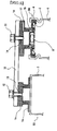
- Fig.3 is a schematic cross-sectional view showing the connecting state of the connection structure between unit cells of the present invention.
- Fig.4 is a schematic cross-sectional view showing a state prior to the connection of the connection structure between unit cells by a screw fitting.
- Fig.5 is a schematic cross-sectional view showing the connection structure of adjacent unit cells.
- Fig.6 is an oblique view showing a fixed frame.
- Hereinafter, referring to the attached drawings, one embodiment of the present invention is explained. Fig.1 is a schematic cross-sectional view showing a state prior to the connection of the connection structure between unit cells of the present invention. In a battery B1 shown in the upper portion, the first ring made of a
metal 1a having a flange is jointed at the bottom surface of a bottomedcylindrical case 2 together in a conductive manner beforehand. In a battery B2 shown in the lower portion, the second ring made of ametal 1b having a flange is jointed in the upper portion of thesealing plate 3 together in a conductive manner beforehand. Junction is preferably made for example, by welding. - The sealing
plate 3 and the second ring made of ametal 1b jointed together and integrated tightly close the battery interposing agasket 4 therebetween. In the drawing, an inner diameter of the first ring made of ametal 1a and an outer diameter of the second ring made of ametal 1b are designed to have substantially the same size. Designed as such, the first ring made of ametal 1a and the second ring made of ametal 1b can be fitted with no space therebetween. Composed as such, a unit cell B1 and a unit cell B2 can be connected electrically and mechanically. In addition, by sandwiching a metal foil (not illustrated) for fitting in the gap between the first ring made of ametal 1a and the second ring made of ametal 1 b, electrical resistance can further be inhibited. Materials for metal foils are preferably aluminum (Al), copper (Cu), nickel (Ni), or alloys whose main materials are aluminum (Al), copper (Cu), and nickel (Ni). - Even when metal foils are fitted without gap, lowering in mechanical strength and increase in contact resistance caused by looseness in fitting portion are not assumed to be a big problem in a fixed state or charge and discharge at low current. However, for the mobile uses like automobile uses, since vibration inevitably occurs, there is high risk that the loosening at the fitting portion occurs. It is assumed this causes the problem of lowering in mechanical strength and increase in contact resistance, thereby causing some trouble at the time of using batteries. Therefore, preferably in a fitted state, by laser welding on four or six points at an interval of 90°or 60°in the outer periphery of a cylindrical portion of a ring made by a metal, for example, mechanical strength in the fitting portion can be improved and the electrical resistance can be lowered. Since the present invention enables the application of laser welding or arc welding, a structure which can enhance contact strength can be realized. When welded and jointed by this method, compared with the resistance at a jointed portion subject to simple fitting, lowering in the electrical resistance by 0.2 to 0.3 mΩ which is an actual measurement value was acknowledged. For example, regarding the batteries used for hybrid electrical vehicles, the current sometimes reaches as high as 150 A, though instantaneously. When used with such a large amount of current, the lowering of battery voltage by 30 to 45 mV can be calculated from said electrical resistance value, and therefore, lowering the electrical resistance at the connecting portion as disclosed in the present invention becomes the important factor for the batteries for hybrid electric vehicles.
- Fig.2 shows the oblique view showing the first ring made of a
metal 1a and the second ring made of ametal 1b and it was made clear that the fitting portion should have a cylindrical shape and its thickness should be not less than 1.5 mm considering the strength and the electrical resistance when fitted, and desirably, 2 to 3 mm, and that the lower limit of the thickness should be within the aforementioned range. Increasing the lower limit over the aforementioned range further improves strength and electrical resistance, however, the battery weight increases and high output is required for welding the fitting portion mentioned later and considering the bad effect caused by the temperature rise at the time of welding, as thickness of cylindrical portion, said designated range is appropriate. - In the present invention, since it is desirable to secure satisfactory fitting strength and to weld the fitting portion by laser, it is necessary to set the length of the
cylindrical portions metal - From such a viewpoint, as a result of acknowledging the relationship between the length of
cylindrical portions - The thickness of
flanges metal cylindrical battery case 2 which is also one electrode terminal or the sealingplate 3 which is also another electrode terminal at the time of integration by a spot welding is found to be effective for improvement in welding strength when said thickness is around 0.5 mm. Since this thickness is substantially the same as that of the material which composes a bottomedcylindrical battery case 2 and the sealingplate 3, it is desirable that the thickness of theflanges flanges cylindrical battery case 2 and the sealingplate 3. - Further, in the present invention, welding is available not only by the spot welding but also by the socalled inverter welding method using an inverter DC power source. In this case, stronger welding is available since structure of intensively applying a current to the protruded portion provided on the same radius of the welded surface of
flanges - The explanation was made when an inner diameter of the first ring made of a
metal 1a and an outer diameter of the second ring made of ametal 1b have the specific size at the fitting portion. However, not limited to such an embodiment, by making the inner diameter of the tip end of the fitting portion of the first ring made of ametal 1a large, and by making the inner diameter of the portion which is near to theflange 23 small, and by making the tip end portion of the outer diameter of the corresponding second ring made of ametal 1b small and by making the outer diameter of the portion which is near to theflange 24 large, firm fixture is available and effective. Of course, the structure in which the second ring made of ametal 1b is fitted outside of the first ring made of ametal 1a may be employed. - As mentioned above, by the structure of the present invention, as remarkable characteristics different from the prior arts, the first ring made of a
metal 1a can be directly welded in a bottomedcylindrical case 2 in the step before a power generating element and electrolyte are contained in thebattery case 2. Likewise, the second ring made of ametal 1b can be welded in asealing plate 3. In other words, before assembling metal connection bodies as a battery, they can be manufactured as parts and compared with prior arts, the welding part can be made firm. As a result, the reduction in the electrical resistance can be expected and since the welding strength between the first ring made of ametal 1a and the bottomedcylindrical case 2 and the welding strength between the second ring made of ametal 1b and the sealingplate 3 are improved. - Next, in Fig.2, a ventilating
groove 7 is hereby explained. Generally, in this kind of a battery, arubber valve 6 shown in Fig.1 is internally fitted in the sealingplate 3. When the pressure in the cell abnormally rises, therubber valve 6 is deformed and the gas is exhausted from the inside. However, in the present invention, by the fitting of the first ring made of ametal 1a and the second ring made of ametal 1b, since inside of therings groove 7 which can exhaust the gas outside is formed at least on one jointed surface offlanges - Compared with the conventional art, in the present invention, by thickening the thickness of the
cylindrical portions metal 1a and the second ring made of ametal 1b, electrical resistance can be lowered. As a result, in the fitted state as shown in Fig.3, even when the distance A betweenflanges metal 1a and the second ring made of ametal 1b can be exposed is available, function with excellent heat radiation performance can be added. Therefore, in the battery system accompanied by temperature rise by charge and discharge, the rise in temperature can be inhibited. In addition, by inserting the fixingframe 18 between unit cells, mechanical strength against bending of module batteries can be improved. Here, when the fixingframe 18 covers all the spaces between unit cells, fitting portions or screw fitting portions cannot be welded thereby lowering the heat radiation performance. Therefore, as shown in Fig.6, it is preferable that the fixingframe 18 is provided with the supportingportion 18a which can support on two portions or more thereby enabling welding of jointed portions or screw fitting portions and ventilating air. - Currently used nickel and hydrogen batteries deteriorate their battery characteristics such as lowering in charge and discharge efficiency, lowering in the cycle life, and the like by the rise in battery temperature. In the present invention, as mentioned before, since the battery structure with excellent heat radiation performance can be achieved, it is anticipated that the deterioration in battery characteristics can be inhibited in the battery system in which bad effect is concerned by the temperature rise. In addition, as shown in Fig.3, although explanation was made on the structure capable of fitting the first ring made of a
metal 1a and the second ring made of ametal 1b, another structure is also available in which a screw groove (female screw) 8 is formed inside of a cylindrical portion of the first ring made of ametal 1a and a screw groove (male screw) 9 corresponding to the outside of a cylindrical portion of the second ring made of ametal 1b, thereby connecting the first ring made of ametal 1a and the second ring made of ametal 1b with a screw fitting as shown in Fig.4. - In Fig.4, in the case of providing
screw grooves metal 1a and a ring made of ametal 1b, as in the case of the above mentioned fitting method, firm fixture by applying laser welding or arc welding to a screw fitting portion after connecting by a screw fit is available and the structure with an exposed connecting portion is also available. Further, when connected by a fitting method or screw fitting method, by fixing with fitting or screw fitting interposing a metal foil (not illustrated) between the first ring made of ametal 1a and the second ring made of ametal 1b, the strength is further improved. As materials for metal foils, aluminum (A1), copper (Cu), nickel (Ni), or alloys whose main materials are aluminum (A1), copper (Cu), or nickel (Ni) are preferable. - Heretofore, regarding the embodiment of the invention, the explanation has been made on a method for connecting unit cells in a linear manner. In order to obtain desired voltage, connecting a plurality of batteries in series in a state of being bent by 180 degrees is also required. In this case, as shown in Fig.5, in a state where the first ring made of a
metal 1a and the second ring made of ametal 1b used at the time of linear connection are fixed to the battery, further, the first connector made of ametal 1c and the second connector made of ametal 1 d are fitted or screw fitted respectively. Since screw pores 13 and 14 are provided at the center of the first and the second connectors made of ametal plate 15 andbolts pore 17 is preferably provided on the second connector made of ametal 1 d to be fitted and screw fitted in the side with a sealingplate 3. - Regarding the connection structure between batteries related to the present invention, electrical resistance at the connecting portion was measured. Batteries to be measured are D sized batteries (cylindrical sealed batteries with an outer diameter of 17 mm and a height of 56 mm by the single size). As shown in Fig.2, the first ring made of a
metal 1a was welded to asealing plate 3 which is a positive electrode terminal. The thickness of aflange 23 of the first ring made of ametal 1a used here was 0.5 mm, and the outer diameter was 23 mm, the outer diameter of acylindrical portion 21 was 17 mm, and the inner diameter was 13.8 mm. The second ring made of ametal 1b was welded to a bottom portion of abattery case 2 which is a negative electrode terminal. The thickness of aflange 24 of the second ring made of ametal 1b was 0.5 mm, and the outer diameter was 20 mm, and the outer diameter of acylindrical portion 22 was 13.7 mm, and the inner diameter of was 10 mm. - A connection system, the presence or absence of copper foils and of laser welding are as shown in the table 1. As a metal foil used for lowering the electrical resistance of a fitting portion and a screw fitting portion, a copper foil with a thickness of 20 µm was used. In addition, using a laser welder (manufactured by MIYACHI CORPORATION: type ML-2550A), irradiation was applied for 0.1 second with an irradiating diameter of 0.6mm and with an output of 5.4kW. When connected by screw fitting, a female screw of M16 is formed in an inner side surface of a cylindrical portion of the first ring made of a
metal 1a and a male screw of M16 is formed in an outer side surface of a cylindrical portion of the second ring made of ametal 1b.Table 1 Result of measurement of electrical resistance of a connection method and of a connection portion Connection system The presence of copper foil at a connecting portion Laser welding Electrical resistance at the connecting portion (mΩ) Yes or No Number of laser points Fitting method Present Not present No -- 1.31 -- 0.81 Not present Yes 4 0.56 6 0.51 8 0.49 Screw fitting method Not present Present No -- 1.55 -- 0.82 Not present Yes 4 0.58 6 0.52 8 0.50 - From the result of measurement of electrical resistance in Table 1, it was found that contact resistance can be reduced by interposing a copper foil at a jointed portion. In addition, by welding with a laser, it was found that the effect is even more remarkable. By increasing the number of the points of laser welding, the contact resistance was reduced, however, when the number of the points are unnecessarily increased, there is a concern that mechanical strength might be lowered, and therefore, 6 to 8 points are considered to be the most appropriate.
- The value of resistance when simply fitted or screw fitted was 1.31 to 1.55 mΩ. This value has no bad effect from the practical view point judging from that the voltage decreases by 65.5 to 77.5 mV when 50 A of current is applied by a nickel cadmium battery or nickel hydroxide battery practically used as a battery for large current and that the operation voltage of the battery is 1.2 V, the voltage decreases by more than 5 %.
Claims (20)
- A connection structure between unit cells connecting a plurality of batteries in series with bottomed cylindrical battery cases which function as electrode terminals on one side, sealing plates which close the opening portions of the battery cases which function as electrode terminals on another side, wherein the first ring having a flange is jointed at a bottom portion of a battery case of one battery in a conductive manner, the second ring having a flange is jointed at an upper portion of a sealing plate of an adjacent battery in a conductive manner, and said first ring and said second ring are fitted together.
- The connection structure between unit cells as set forth in claim 1, wherein a ventilating groove which ventilates to atmospheric air is provided on a jointed surface of at least one flange of said first ring and said second ring.
- The connection structure between unit cells as set forth in claim 1, wherein said first ring and said second ring made of a meal are welded to be jointed.
- The connection structure between unit cells as set forth in claim 3, wherein said welding is laser welding.
- The connection structure between unit cells as set forth in claim 1, wherein a distance between a flange of said first ring and a flange of said second ring is not less than 3 mm, resin fixture is available at more than two portions around the connected unit cells to keep the distance for air flow.
- The connection structure between unit cells as set forth in claim 1, wherein a part or a whole of said first ring and said second ring are exposed outward under a state of connecting unit cells.
- The connection structure between unit cells as set forth in claim 1, wherein said first ring and said second ring are fitted or screw fitted interposing a metal foil.
- The connection structure between unit cells as set forth in claim 7, wherein the materials of said metal foil are aluminum (Al), copper (Cu), nickel (Ni), or alloys whose main materials are aluminum (Al), copper (Cu), or nickel (Ni).
- A connection structure between unit cells connecting a plurality of batteries in series with bottomed cylindrical battery cases which function as electrode terminals on one side, sealing plates which close the opening portions of the battery cases which function as electrode terminals on another side, wherein the first ring having a flange is jointed at a bottom portion of a battery case of one battery in a conductive manner, the second ring having a flange is jointed at an upper portion of a sealing plate of another battery in a conductive manner, and a screw groove is formed in an outer side surface of a cylindrical portion of one of said first ring and said second ring and an inner side surface of a cylindrical portion of another of said second ring and said second ring, and said first and said second rings are screw fitted.
- The connection structure between unit cells as set forth in claim 9, wherein a ventilating groove which ventilates to atmospheric air is provided on a jointed surface of at least one flange of said first ring and said second ring.
- The connection structure between unit cells as set forth in claim 9, wherein said first ring and said second ring are welded to be jointed.
- The connection structure between unit cells as set forth in claim 11, wherein said welding is laser welding.
- The connection structure between unit cells as set forth in claim 9, wherein a distance between a flange of said first ring and a flange of said second ring is not less than 3 mm, resin fixture is available at more than two portions around the connected unit cells to keep the distance for air flow.
- The connection structure between unit cells as set forth in claim 9, wherein a part or a whole of said first ring and said second ring are exposed outward under a state of connecting unit cells.
- The connection structure between unit cells as set forth in claim 9, wherein said first ring and said second ring are fitted or screw fitted interposing a metal foil.
- The connection structure between unit cells as set forth in claim 15, wherein the materials of said metal foil are aluminum (Al), copper (Cu), nickel (Ni), or alloys whose main materials are aluminum (Al), copper (Cu), or nickel (Ni).
- A connection structure between unit cells connecting a plurality of batteries in series with bottomed cylindrical battery cases which function as electrode terminals on one side, sealing plates which close the opening portions of the battery cases which function as electrode terminals on another side, wherein the first ring having a flange is jointed at a bottom portion of a battery case of one battery in a conductive manner, the second ring having a flange is jointed at an upper portion of a sealing plate of another battery in a conductive manner, and a first connector and a second connector provided with a screw whole at the center are fitted or screw fitted in said first ring and said second ring respectively, and a connecting plate which connects said first connector and said second connector is connected in a conductive manner.
- The connection structure between unit cells as set forth in claim 17, wherein said first ring and said second ring are fitted or screw fitted interposing a metal foil.
- The connection structure between unit cells as set forth in claim 18, wherein the materials of said metal foil are aluminum (Al), copper (Cu), nickel (Ni), or alloys whose main materials are aluminum (Al), copper (Cu), or nickel (Ni).
- A manufacturing method of unit cells, comprising of jointing the first ring having a flange to a bottom portion of a battery case of one battery in a conductive manner, and/or jointing the second ring having a flange to an upper portion of a sealing plate of another battery in a conductive manner, and inserting generating element which includes electrodes, a separator, an electrolyte in said battery case and connecting said electrodes to said battery case and said sealing plate electrically and closing the opening portion of said battery case with said sealing plate.
Applications Claiming Priority (1)
| Application Number | Priority Date | Filing Date | Title |
|---|---|---|---|
| JP2005375324A JP5015455B2 (en) | 2005-12-27 | 2005-12-27 | Connection structure between secondary cells |
Publications (2)
| Publication Number | Publication Date |
|---|---|
| EP1804312A2 true EP1804312A2 (en) | 2007-07-04 |
| EP1804312A3 EP1804312A3 (en) | 2010-06-30 |
Family
ID=37872180
Family Applications (1)
| Application Number | Title | Priority Date | Filing Date |
|---|---|---|---|
| EP06127238A Withdrawn EP1804312A3 (en) | 2005-12-27 | 2006-12-27 | Connection structure between unit cells |
Country Status (5)
| Country | Link |
|---|---|
| US (1) | US7887947B2 (en) |
| EP (1) | EP1804312A3 (en) |
| JP (1) | JP5015455B2 (en) |
| KR (1) | KR100825908B1 (en) |
| CN (1) | CN100565976C (en) |
Cited By (6)
| Publication number | Priority date | Publication date | Assignee | Title |
|---|---|---|---|---|
| EP2253037A4 (en) * | 2008-02-15 | 2014-03-12 | Atieva Inc | METHOD FOR ELECTRICALLY CONNECTING CELL TERMINALS IN A BATTERY PACK |
| EP2962343A4 (en) * | 2013-02-27 | 2016-11-09 | Ioxus Inc | ASSEMBLY OF ENERGY STORAGE DEVICES |
| US9892868B2 (en) | 2013-06-21 | 2018-02-13 | Ioxus, Inc. | Energy storage device assembly |
| US9899643B2 (en) | 2013-02-27 | 2018-02-20 | Ioxus, Inc. | Energy storage device assembly |
| CN109065825A (en) * | 2018-07-27 | 2018-12-21 | 深圳市瑞德丰精密制造有限公司 | The moulding process of Copper-Aluminum compound pole block |
| EP3052842B1 (en) * | 2013-09-30 | 2020-01-22 | Danfoss A/S | A method for attaching an object to a valve housing |
Families Citing this family (11)
| Publication number | Priority date | Publication date | Assignee | Title |
|---|---|---|---|---|
| KR100913174B1 (en) * | 2007-04-04 | 2009-08-19 | 삼성에스디아이 주식회사 | Battery module |
| JP5423431B2 (en) * | 2010-01-27 | 2014-02-19 | トヨタ自動車株式会社 | Storage structure of storage module and method for manufacturing storage module |
| CN102947973A (en) * | 2010-06-14 | 2013-02-27 | 松下电器产业株式会社 | Battery assembly production method and battery assembly |
| KR20140123693A (en) * | 2013-04-15 | 2014-10-23 | 삼성에스디아이 주식회사 | Battery Pack |
| KR102381778B1 (en) * | 2015-02-16 | 2022-04-01 | 삼성에스디아이 주식회사 | Battery pack |
| DE102015207550A1 (en) | 2015-04-24 | 2016-10-27 | Robert Bosch Gmbh | Cell connector with tolerance compensation |
| CN107994197B (en) * | 2017-11-24 | 2023-07-07 | 晶丰电子封装材料(武汉)有限公司 | Connection structure and connection method of column type rechargeable battery and base |
| KR102434896B1 (en) | 2017-12-21 | 2022-08-22 | 주식회사 엘지에너지솔루션 | Battery connector for series connection of batteries and battery pack including the same |
| DE102019200349A1 (en) * | 2019-01-14 | 2020-07-16 | Robert Bosch Gmbh | Battery cell connector for the serial connection of battery cells |
| CN114142135B (en) * | 2021-11-09 | 2025-06-13 | 广东美尼麦格松电源系统有限公司 | Rechargeable battery, battery controller, and assembly method of rechargeable battery |
| JP2025014190A (en) * | 2023-07-18 | 2025-01-30 | 株式会社Aescジャパン | Battery cell, battery module manufacturing method, and battery module |
Family Cites Families (17)
| Publication number | Priority date | Publication date | Assignee | Title |
|---|---|---|---|---|
| GB108849A (en) | 1916-08-08 | 1918-02-28 | Svenska Ackumulator Ab | Improvements in Electric Batteries. |
| DE494929C (en) | 1929-01-30 | 1930-03-31 | Gerhard Jaeger | Dry battery with several elements connected in series |
| JPS51162935U (en) * | 1975-06-19 | 1976-12-25 | ||
| US4077268A (en) * | 1976-07-14 | 1978-03-07 | Hill John W | Garage door operator |
| JPS5564273U (en) * | 1978-10-27 | 1980-05-01 | ||
| US4746220A (en) * | 1985-04-18 | 1988-05-24 | Noritake Co., Limited | Screw type extruding or kneading machine and screw used therein |
| JP2801922B2 (en) * | 1989-03-29 | 1998-09-21 | 旭化成工業株式会社 | Non-aqueous battery and method for welding lead tab thereof |
| JPH08222201A (en) * | 1995-02-14 | 1996-08-30 | Toyota Autom Loom Works Ltd | Battery |
| JP3312853B2 (en) | 1996-09-26 | 2002-08-12 | 松下電器産業株式会社 | Battery connection structure |
| JP2000077057A (en) * | 1998-08-28 | 2000-03-14 | Ngk Insulators Ltd | Lithium secondary battery |
| JP3092923B2 (en) | 1998-09-01 | 2000-09-25 | 松下電器産業株式会社 | Connection structure between batteries, method thereof, battery, battery module, and method of manufacturing the same |
| JP3723433B2 (en) * | 2000-03-30 | 2005-12-07 | 三洋電機株式会社 | Battery pack and manufacturing method thereof |
| JP3733009B2 (en) | 2000-03-30 | 2006-01-11 | 三洋電機株式会社 | Manufacturing method and manufacturing apparatus of assembled battery |
| US6844110B2 (en) | 2000-05-24 | 2005-01-18 | Ngk Insulators, Ltd. | Lithium secondary cell and assembly thereof |
| FR2819105B1 (en) * | 2001-01-04 | 2004-06-18 | Cit Alcatel | ELECTRICAL CONNECTION SYSTEM FOR ELECTROCHEMICAL GENERATORS |
| JP4356314B2 (en) * | 2002-12-20 | 2009-11-04 | パナソニック株式会社 | Battery and battery pack |
| US20050281611A1 (en) * | 2004-06-17 | 2005-12-22 | Seals-It | Seal component for use with a spherical rod end assembly |
-
2005
- 2005-12-27 JP JP2005375324A patent/JP5015455B2/en not_active Expired - Fee Related
-
2006
- 2006-03-31 KR KR1020060029865A patent/KR100825908B1/en not_active Expired - Fee Related
- 2006-06-06 CN CNB2006100879067A patent/CN100565976C/en not_active Expired - Fee Related
- 2006-12-26 US US11/645,784 patent/US7887947B2/en not_active Expired - Fee Related
- 2006-12-27 EP EP06127238A patent/EP1804312A3/en not_active Withdrawn
Cited By (7)
| Publication number | Priority date | Publication date | Assignee | Title |
|---|---|---|---|---|
| EP2253037A4 (en) * | 2008-02-15 | 2014-03-12 | Atieva Inc | METHOD FOR ELECTRICALLY CONNECTING CELL TERMINALS IN A BATTERY PACK |
| EP2962343A4 (en) * | 2013-02-27 | 2016-11-09 | Ioxus Inc | ASSEMBLY OF ENERGY STORAGE DEVICES |
| US9899643B2 (en) | 2013-02-27 | 2018-02-20 | Ioxus, Inc. | Energy storage device assembly |
| US9892868B2 (en) | 2013-06-21 | 2018-02-13 | Ioxus, Inc. | Energy storage device assembly |
| EP3052842B1 (en) * | 2013-09-30 | 2020-01-22 | Danfoss A/S | A method for attaching an object to a valve housing |
| US10814426B2 (en) | 2013-09-30 | 2020-10-27 | Danfoss A/S | Method for attaching an object to a structure |
| CN109065825A (en) * | 2018-07-27 | 2018-12-21 | 深圳市瑞德丰精密制造有限公司 | The moulding process of Copper-Aluminum compound pole block |
Also Published As
| Publication number | Publication date |
|---|---|
| KR100825908B1 (en) | 2008-04-29 |
| CN1992389A (en) | 2007-07-04 |
| EP1804312A3 (en) | 2010-06-30 |
| JP5015455B2 (en) | 2012-08-29 |
| CN100565976C (en) | 2009-12-02 |
| KR20070068976A (en) | 2007-07-02 |
| JP2007179816A (en) | 2007-07-12 |
| US7887947B2 (en) | 2011-02-15 |
| US20070184342A1 (en) | 2007-08-09 |
Similar Documents
| Publication | Publication Date | Title |
|---|---|---|
| US7887947B2 (en) | Connection structure between unit cells | |
| US12074345B2 (en) | Terminal, secondary battery provided with same, and methods for producing same | |
| US7785377B2 (en) | Sealed battery and method for manufacturing the same | |
| US8404380B2 (en) | Inter-connector between unit cells and serial cell | |
| JP5528746B2 (en) | Assembled battery | |
| CN114976180A (en) | Battery, and battery pack and vehicle including the same | |
| US20220085469A1 (en) | Terminal for secondary battery and secondary battery provided with the terminal | |
| CN110034250A (en) | Enclosed-type battery, battery pack, the manufacturing method of the manufacturing method of enclosed-type battery and battery pack | |
| JP7332999B2 (en) | sealed battery | |
| CN112838334B (en) | sealed battery | |
| US20070099074A1 (en) | Secondary battery for medium and large size battery module | |
| US20240170809A1 (en) | Tab welding method, welding tool, battery cell, battery, and electric device | |
| KR20150135163A (en) | Cap-assembly of litium ion battery with high capacity and power | |
| JP7628100B2 (en) | Battery and method for manufacturing battery | |
| JP6764569B2 (en) | Sealed battery | |
| US20250015458A1 (en) | Electricity storage device, terminal for electricity storage device, and method for manufacturing electricity storage device | |
| KR101201815B1 (en) | Secondary battery | |
| US20260066400A1 (en) | Prismatic type secondary battery and manufacturing method thereof | |
| US12469913B2 (en) | Secondary battery | |
| US20260074336A1 (en) | Prismatic type secondary battery and manufacturing method thereof | |
| KR20250027443A (en) | Can assembly having welding error prevention structure, electrode including the structure, heading machine for manufacturing the electrode, cylindrical secondary battery including electrode, and secondary battery pack including the cylindrical secondary battery | |
| JP4665427B2 (en) | Flat sealed battery | |
| JP2026512726A (en) | Battery cell, battery pack containing the same, automobile, and method for manufacturing the same | |
| KR20250037229A (en) | Can assembly having welding weld ability improvement structure, electrode including the structure, cylindrical secondary battery including electrode, and secondary battery pack including the cylindrical secondary battery | |
| KR101583443B1 (en) | Method of manufacturing cap-assay of litium ion battery with high capacity and power |
Legal Events
| Date | Code | Title | Description |
|---|---|---|---|
| PUAI | Public reference made under article 153(3) epc to a published international application that has entered the european phase |
Free format text: ORIGINAL CODE: 0009012 |
|
| AK | Designated contracting states |
Kind code of ref document: A2 Designated state(s): AT BE BG CH CY CZ DE DK EE ES FI FR GB GR HU IE IS IT LI LT LU LV MC NL PL PT RO SE SI SK TR |
|
| AX | Request for extension of the european patent |
Extension state: AL BA HR MK YU |
|
| PUAL | Search report despatched |
Free format text: ORIGINAL CODE: 0009013 |
|
| AK | Designated contracting states |
Kind code of ref document: A3 Designated state(s): AT BE BG CH CY CZ DE DK EE ES FI FR GB GR HU IE IS IT LI LT LU LV MC NL PL PT RO SE SI SK TR |
|
| AX | Request for extension of the european patent |
Extension state: AL BA HR MK RS |
|
| 17P | Request for examination filed |
Effective date: 20101112 |
|
| AKX | Designation fees paid |
Designated state(s): FR |
|
| REG | Reference to a national code |
Ref country code: DE Ref legal event code: R108 Effective date: 20110208 Ref country code: DE Ref legal event code: 8566 |
|
| STAA | Information on the status of an ep patent application or granted ep patent |
Free format text: STATUS: THE APPLICATION IS DEEMED TO BE WITHDRAWN |
|
| 18D | Application deemed to be withdrawn |
Effective date: 20130702 |