EP1804117A1 - Camera module - Google Patents
Camera module Download PDFInfo
- Publication number
- EP1804117A1 EP1804117A1 EP06127233A EP06127233A EP1804117A1 EP 1804117 A1 EP1804117 A1 EP 1804117A1 EP 06127233 A EP06127233 A EP 06127233A EP 06127233 A EP06127233 A EP 06127233A EP 1804117 A1 EP1804117 A1 EP 1804117A1
- Authority
- EP
- European Patent Office
- Prior art keywords
- cut filter
- camera module
- lens unit
- attachment portion
- lower edges
- Prior art date
- Legal status (The legal status is an assumption and is not a legal conclusion. Google has not performed a legal analysis and makes no representation as to the accuracy of the status listed.)
- Withdrawn
Links
Images


Classifications
-
- G—PHYSICS
- G03—PHOTOGRAPHY; CINEMATOGRAPHY; ANALOGOUS TECHNIQUES USING WAVES OTHER THAN OPTICAL WAVES; ELECTROGRAPHY; HOLOGRAPHY
- G03B—APPARATUS OR ARRANGEMENTS FOR TAKING PHOTOGRAPHS OR FOR PROJECTING OR VIEWING THEM; APPARATUS OR ARRANGEMENTS EMPLOYING ANALOGOUS TECHNIQUES USING WAVES OTHER THAN OPTICAL WAVES; ACCESSORIES THEREFOR
- G03B11/00—Filters or other obturators specially adapted for photographic purposes
-
- H—ELECTRICITY
- H04—ELECTRIC COMMUNICATION TECHNIQUE
- H04N—PICTORIAL COMMUNICATION, e.g. TELEVISION
- H04N23/00—Cameras or camera modules comprising electronic image sensors; Control thereof
- H04N23/50—Constructional details
- H04N23/55—Optical parts specially adapted for electronic image sensors; Mounting thereof
-
- G—PHYSICS
- G02—OPTICS
- G02B—OPTICAL ELEMENTS, SYSTEMS OR APPARATUS
- G02B13/00—Optical objectives specially designed for the purposes specified below
- G02B13/001—Miniaturised objectives for electronic devices, e.g. portable telephones, webcams, PDAs, small digital cameras
- G02B13/0015—Miniaturised objectives for electronic devices, e.g. portable telephones, webcams, PDAs, small digital cameras characterised by the lens design
-
- G—PHYSICS
- G02—OPTICS
- G02B—OPTICAL ELEMENTS, SYSTEMS OR APPARATUS
- G02B5/00—Optical elements other than lenses
- G02B5/20—Filters
- G02B5/208—Filters for use with infrared or ultraviolet radiation, e.g. for separating visible light from infrared and/or ultraviolet radiation
-
- G—PHYSICS
- G02—OPTICS
- G02B—OPTICAL ELEMENTS, SYSTEMS OR APPARATUS
- G02B7/00—Mountings, adjusting means, or light-tight connections, for optical elements
- G02B7/006—Filter holders
-
- G—PHYSICS
- G03—PHOTOGRAPHY; CINEMATOGRAPHY; ANALOGOUS TECHNIQUES USING WAVES OTHER THAN OPTICAL WAVES; ELECTROGRAPHY; HOLOGRAPHY
- G03B—APPARATUS OR ARRANGEMENTS FOR TAKING PHOTOGRAPHS OR FOR PROJECTING OR VIEWING THEM; APPARATUS OR ARRANGEMENTS EMPLOYING ANALOGOUS TECHNIQUES USING WAVES OTHER THAN OPTICAL WAVES; ACCESSORIES THEREFOR
- G03B17/00—Details of cameras or camera bodies; Accessories therefor
-
- H—ELECTRICITY
- H04—ELECTRIC COMMUNICATION TECHNIQUE
- H04N—PICTORIAL COMMUNICATION, e.g. TELEVISION
- H04N23/00—Cameras or camera modules comprising electronic image sensors; Control thereof
- H04N23/57—Mechanical or electrical details of cameras or camera modules specially adapted for being embedded in other devices
Definitions
- the present invention relates to a camera module, and more particularly to a relatively small camera module to be mounted on an electronic apparatus such as a back monitor for a vehicle and a cellular phone and the like.
- a relatively small camera module is mounted on an electronic apparatus such as a cellular phone and the like.
- a camera module includes an image pick-up device such as a CMOS sensor or a CCD sensor.
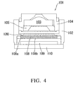
- FIG. 4 is a cross-sectional view showing a conventional camera module 101.
- the camera module 101 includes a housing 102 which constitutes an outer shell of the camera module 101, a lens unit 103 having an optical system of the camera module 101, a cylindrical barrel 104 made of a synthetic resin for holding the lens unit 103, a ring-shaped stopper 105 made of a synthetic resin for fixing the lens unit 103 inside the barrel 104, a plate-shaped IR cut filter 108 disposed below the lens unit 103, an image pick-up device 109 provided below the IR cut filter 108, and a substrate 110 on which the image pick-up device 109 is mounted.
- the IR cut filter is a rectangular glass part which reflects infrared rays while allowing visible light to be transmitted therethrough.
- the IR cut filter 108 is attached to an IR cut filter attachment portion 120 formed inside the housing 102 with an adhesive.
- the IR cut filter 108 When the IR cut filter 108 is attached to the IR cut filter attachment portion 120, the IR cut filter 108 is grasped with tweezers and then it is placed on the IR cut filter attachment portion 120. In this state, the IR cut filter 108 is bonded to the IR cut filter attachment portion 120 by applying an adhesive to the periphery of the IR cut mounting filter 108.
- a conventional camera module is disclosed in JP-A No. 2005-72978 .
- the IR cut filter 108 is grasped with tweezers. Therefore, there is a case that a peripheral edge 108a of the IR cut filter 108 is slightly chipped, and such a minute chip of the glass material of the IR cut filter 8 falls on the surface of the image pick-up device 109 and adheres thereto. In such a case, there is a problem in that it is not possible to take a fine image by the camera module 101.
- the present invention has been made in view of the above problem. It is, therefore, an object of the present invention to provide a camera module which can prevent a peripheral edge of an IR cut filter from being chipped when the IR cut filter is attached to an IR filter attachment portion of the camera module.
- the present invention is directed to a camera module which includes a housing which constitutes an outer shell of the camera module; a lens unit having an optical system of the camera module; a cylindrical barrel made of a synthetic resin for holding the lens unit; a plate-shaped IR cut filter disposed below the lens unit; and an image pick-up device provided below the IR cut filter.
- the IR cut filter has a bottom surface which faces the image pick-up device, wherein the bottom surface is defined by lower edges, and the lower edges are chamfered.
- the IR cut filter is disposed within the housing so that its bottom surface faces the image pick-up device, and the four lower edges of the IR cut filter which define the bottom surface are chamfered. Therefore, when the IR cut filter 8 is grasped with tweezers for attaching it to the IR cut filter attachment portion, there is less possibility that the peripheral edge of the IR cut filter is chipped. As a result, it is possible to prevent a minute chip chipped from the IR cut filter from adhering to the surface of the image pick-up device 9 thereby making it difficult to obtain a fine image.
- the housing has an IR filter attachment portion having stepped walls which surround the peripheral edges of the IR cut filter, and the lower edges of the stepped walls of the IR filter attachment portion are also chamfered.
- the camera module of the present invention having the IR cut filter attachment portion 20 with the chamfered lower edges can prevent occurrence of such undesirable reflection of light.
- the image pick-up device from being affected by such undesirable reflection of light, thereby enabling a fine image to be taken by the camera module.
- FIG. 1 is a cross-sectional view showing a camera module 1 according to an embodiment of the present invention. Note that in the following description, the terms “upper” or “top” and “lower” or “bottom” are respectively used to denote the direction in FIG. 1 where a barrel 4 of a camera module 1 is located and the direction in FIG. 1 where a substrate 10 is located.
- the camera module 1 is composed from a housing 2 which constitutes an outer shell of the camera module 1; a lens unit 3 having an optical system of the camera module 1; a cylindrical barrel 4 made of a synthetic resin for holding the lens unit 3; a plate-shaped IR cut filter 8 disposed below the lens unit 3; and an image pick-up device 9 provided below the IR cut filter 8.
- the IR cut filter 8 is formed from a rectangular glass member and has a bottom surface 8b which faces the image pick-up device 9, wherein the bottom surface is defined by four lower edges, and the lower edges are chamfered.
- the housing 2 is a component having a roughly cubic shape and having a hollow space therein, and made of a synthetic resin material.
- the barrel 4 (which will be described later in detail) is disposed inside the hollow space of the housing 2.
- an IR cut filter attachment portion 20 to which the IR cut filter 8 is attached with an adhesive.
- the IR cut filter attachment portion 20 is provided on the lower side of the hollow space of the housing 2.
- the IR cut filter attachment portion 20 includes stepped walls 21 which surround the peripheral edges of the IR cut filter 8 and support ribs 22 which protrude inwardly from the upper portions of the stepped walls 21 to define an opening 23.
- the IR cut filter 8 is placed on the support ribs 22 so that the peripheral edges of the IR cut filter 8 are surrounded by the stepped walls 21.
- the lower edges 21b of the stepped walls 21 of the IR filter attachment portion 20 are also chamfered.
- the barrel 4 is a cylindrical component made of a synthetic resin and having a hollow space therein. Inside the hollow space of the barrel 4, the lens unit 3 is provided, and a stopper 5 is also provided inside the hollow space below the lens unit 3 to hold the lens unit 3 inside the barrel 4.
- the lens unit 3 constitutes an optical system of the camera module 1.
- the stopper 5 is a ring-shaped member made of a synthetic resin material. As described above, the stopper 5 is disposed in the hollow space of the barrel 4 below the lens unit 3. The stopper 5 is press-fitted into the hollow space of the barrel 4 from the bottom thereof so that the outer circumferential surface of the stopper 5 is in contact with the inner circumferential surface of the barrel 4 and the upper surface of the stopper 5 is also in contact with the bottom of the lens unit 3. In this way, the lens unit 3 is held inside the barrel 4 by the stopper 5.
- the IR cut filter 8 is a rectangular glass member (infrared ray reflection glass) which reflects infrared rays while allowing visible light to be transmitted therethrough. Further, as described above, the IR cut filter 8 is disposed within the housing 2 so that its bottom surface 8b faces the image pick-up device 9. Furthermore, as shown in FIG. 1 and FIG. 2, four lower edges of the IR cut filter 8 which define the bottom surface 8b are chamfered.
- the IR cut filter 8 is manufactured by cutting an infrared ray reflection glass material 80 into a plurality of predetermined pieces.
- the bottom surface of the infrared ray reflection glass material 80 is preliminarily cut along predetermined lines to form grooves 80a each having a V-shaped cross-section. Then, the infrared ray reflection glass material 80 is cut off along the V-shaped grooves 80a, thereby a plurality of IR cut filters 8 each having the chamfered lower edges 8a can be obtained.
- the thus manufactured IR cut filter 8 is attached to the IR cut filter attachment portion 20 provided inside the housing 2 with an adhesive.
- the IR cut filter 8 is grasped with tweezers, and then the IR cut filter 8 is placed on the IR cut filter attachment portion 20 using the tweezers so that the peripheral portion of the top surface thereof is placed on the support ribs 22 and the peripheral edges thereof are surrounded by the stepped walls 21.
- the peripheral portion of the bottom surface of the IR cut filter 8 is bonded to IR cut filter attachment portion 20 (that is, to the stepped walls 21) with an adhesive.
- the reference numeral 9 denotes an image pick-up device disposed below the IR cut filter, and the image pick-up device 9 is mounted on the substrate 10.
- the IR cut filter 8 is disposed within the housing 2 so that its bottom surface 8b faces the image pick-up device 9, and the four lower edges 8a of the IR cut filter 8 which define the bottom surface 8b are chamfered. Therefore, when the IR cut filter 8 is grasped with tweezers for attaching it to the IR cut filter attachment portion 20, there is less possibility that the peripheral edge 8a of the IR cut filter 8 is chipped. As a result, it is possible to prevent a minute chip chipped from the IR cut filter 8 from adhering to the surface of the image pick-up device 9 thereby making it difficult to obtain a fine image.
- the housing 2 is formed with the IR cut filter attachment portion 20, and the stepped walls 21 of the IR cut filter attachment portion 20 which surround the peripheral edges of the IR cut filter 8 have the chamfered lower edges 21b.
- the camera module 1 of this embodiment including the IR cut filter attachment portion 20 having the stepped walls 21 with the chamfered lower edges 21a can prevent occurrence of such undesirable reflection of light. As a result, it is possible to prevent the image pick-up device 9 from being affected by such undesirable reflection of light, thereby enabling a fine image to be obtained by the camera module 1.
Landscapes
- Physics & Mathematics (AREA)
- General Physics & Mathematics (AREA)
- Engineering & Computer Science (AREA)
- Multimedia (AREA)
- Signal Processing (AREA)
- Optics & Photonics (AREA)
- Health & Medical Sciences (AREA)
- Toxicology (AREA)
- Studio Devices (AREA)
- Optical Filters (AREA)
- Transforming Light Signals Into Electric Signals (AREA)
- Lens Barrels (AREA)
Abstract
Description
- The present invention relates to a camera module, and more particularly to a relatively small camera module to be mounted on an electronic apparatus such as a back monitor for a vehicle and a cellular phone and the like.
- A relatively small camera module is mounted on an electronic apparatus such as a cellular phone and the like. Such a camera module includes an image pick-up device such as a CMOS sensor or a CCD sensor. FIG. 4 is a cross-sectional view showing a
conventional camera module 101. Thecamera module 101 includes ahousing 102 which constitutes an outer shell of thecamera module 101, alens unit 103 having an optical system of thecamera module 101, acylindrical barrel 104 made of a synthetic resin for holding thelens unit 103, a ring-shaped stopper 105 made of a synthetic resin for fixing thelens unit 103 inside thebarrel 104, a plate-shapedIR cut filter 108 disposed below thelens unit 103, an image pick-up device 109 provided below theIR cut filter 108, and asubstrate 110 on which the image pick-up device 109 is mounted. - The IR cut filter is a rectangular glass part which reflects infrared rays while allowing visible light to be transmitted therethrough. The
IR cut filter 108 is attached to an IR cutfilter attachment portion 120 formed inside thehousing 102 with an adhesive. - When the
IR cut filter 108 is attached to the IR cutfilter attachment portion 120, theIR cut filter 108 is grasped with tweezers and then it is placed on the IR cutfilter attachment portion 120. In this state, theIR cut filter 108 is bonded to the IR cutfilter attachment portion 120 by applying an adhesive to the periphery of the IRcut mounting filter 108. One example of such a conventional camera module is disclosed inJP-A No. 2005-72978 - As described above, in the
camera module 101, when theIR cut filter 108 is attached to the IR cutfilter attachment portion 120, theIR cut filter 108 is grasped with tweezers. Therefore, there is a case that aperipheral edge 108a of theIR cut filter 108 is slightly chipped, and such a minute chip of the glass material of theIR cut filter 8 falls on the surface of the image pick-up device 109 and adheres thereto. In such a case, there is a problem in that it is not possible to take a fine image by thecamera module 101. - In particular, in the case where such chipping occurs in the lower
peripheral edge 108a of thebottom surface 108b of theIR cut filter 108, such a minute chip of the glass material is likely to fall on the surface of the image pick-updevice 109 and therefore such a problem as described above is likely to occur. - The present invention has been made in view of the above problem. It is, therefore, an object of the present invention to provide a camera module which can prevent a peripheral edge of an IR cut filter from being chipped when the IR cut filter is attached to an IR filter attachment portion of the camera module.
- In order to achieve the above object, the present invention is directed to a camera module which includes a housing which constitutes an outer shell of the camera module; a lens unit having an optical system of the camera module; a cylindrical barrel made of a synthetic resin for holding the lens unit; a plate-shaped IR cut filter disposed below the lens unit; and an image pick-up device provided below the IR cut filter. The IR cut filter has a bottom surface which faces the image pick-up device, wherein the bottom surface is defined by lower edges, and the lower edges are chamfered.
- According to the camera module having the structure described above, the IR cut filter is disposed within the housing so that its bottom surface faces the image pick-up device, and the four lower edges of the IR cut filter which define the bottom surface are chamfered. Therefore, when the
IR cut filter 8 is grasped with tweezers for attaching it to the IR cut filter attachment portion, there is less possibility that the peripheral edge of the IR cut filter is chipped. As a result, it is possible to prevent a minute chip chipped from the IR cut filter from adhering to the surface of the image pick-up device 9 thereby making it difficult to obtain a fine image. - In the camera module according to the present invention, it is preferred that the housing has an IR filter attachment portion having stepped walls which surround the peripheral edges of the IR cut filter, and the lower edges of the stepped walls of the IR filter attachment portion are also chamfered.
- According to the structure described above, although in the conventional camera module in which IR cut filter attachment portion does not have such chamfered lower edges, there is a case that light that has entered into the camera module is diffusely reflected at the angled lower edges of the IR cut filter attachment portion, the camera module of the present invention having the IR cut
filter attachment portion 20 with the chamfered lower edges can prevent occurrence of such undesirable reflection of light. As a result, it is possible to prevent the image pick-up device from being affected by such undesirable reflection of light, thereby enabling a fine image to be taken by the camera module. - The above and other objects, features and advantages of the present invention will be apparent from the following description when taken in conjunction with the accompanying drawings which illustrate preferred embodiments of the present invention by way of example.
-
- FIG. 1 is a cross-sectional view showing a camera module according to an embodiment of the present invention;
- FIG. 2 is a perspective view of an
IR cut filter 8 provided in the camera module shown in FIG. 1; - FIG. 3 is an illustration for explaining a manufacturing process of the
IR cut filter 8 used in the camera module shown in FIG. 1, in which FIG 3(a) shows a glass plate of an infraredray reflection glass 80 from which a plurality of IR cut filters are formed (this figure shows a state before cutting of the glass plate being made), and FIG 3(b) shows a state after the cutting of the glass plate has been made; and - FIG. 4 is a cross-sectional view showing a conventional camera module.
- A camera module according to an embodiment of the present invention will be described below with reference to FIGS. 1 to 3. FIG. 1 is a cross-sectional view showing a
camera module 1 according to an embodiment of the present invention. Note that in the following description, the terms "upper" or "top" and "lower" or "bottom" are respectively used to denote the direction in FIG. 1 where abarrel 4 of acamera module 1 is located and the direction in FIG. 1 where asubstrate 10 is located. - The
camera module 1 is composed from ahousing 2 which constitutes an outer shell of thecamera module 1; alens unit 3 having an optical system of thecamera module 1; acylindrical barrel 4 made of a synthetic resin for holding thelens unit 3; a plate-shapedIR cut filter 8 disposed below thelens unit 3; and an image pick-up device 9 provided below theIR cut filter 8. TheIR cut filter 8 is formed from a rectangular glass member and has abottom surface 8b which faces the image pick-updevice 9, wherein the bottom surface is defined by four lower edges, and the lower edges are chamfered. - In more details, the
housing 2 is a component having a roughly cubic shape and having a hollow space therein, and made of a synthetic resin material. Inside the hollow space of thehousing 2, the barrel 4 (which will be described later in detail) is disposed. Further, inside the hollow space of thehousing 2, there is formed an IR cutfilter attachment portion 20 to which theIR cut filter 8 is attached with an adhesive. Specifically, the IR cutfilter attachment portion 20 is provided on the lower side of the hollow space of thehousing 2. The IR cutfilter attachment portion 20 includesstepped walls 21 which surround the peripheral edges of theIR cut filter 8 and supportribs 22 which protrude inwardly from the upper portions of thestepped walls 21 to define anopening 23. TheIR cut filter 8 is placed on thesupport ribs 22 so that the peripheral edges of theIR cut filter 8 are surrounded by thestepped walls 21. Thelower edges 21b of thestepped walls 21 of the IRfilter attachment portion 20 are also chamfered. - The
barrel 4 is a cylindrical component made of a synthetic resin and having a hollow space therein. Inside the hollow space of thebarrel 4, thelens unit 3 is provided, and astopper 5 is also provided inside the hollow space below thelens unit 3 to hold thelens unit 3 inside thebarrel 4. Thelens unit 3 constitutes an optical system of thecamera module 1. - The
stopper 5 is a ring-shaped member made of a synthetic resin material. As described above, thestopper 5 is disposed in the hollow space of thebarrel 4 below thelens unit 3. Thestopper 5 is press-fitted into the hollow space of thebarrel 4 from the bottom thereof so that the outer circumferential surface of thestopper 5 is in contact with the inner circumferential surface of thebarrel 4 and the upper surface of thestopper 5 is also in contact with the bottom of thelens unit 3. In this way, thelens unit 3 is held inside thebarrel 4 by thestopper 5. - The
IR cut filter 8 is a rectangular glass member (infrared ray reflection glass) which reflects infrared rays while allowing visible light to be transmitted therethrough. Further, as described above, theIR cut filter 8 is disposed within thehousing 2 so that itsbottom surface 8b faces the image pick-up device 9. Furthermore, as shown in FIG. 1 and FIG. 2, four lower edges of theIR cut filter 8 which define thebottom surface 8b are chamfered. - As shown in FIG. 3(a) and FIG. 3(b), the
IR cut filter 8 is manufactured by cutting an infrared rayreflection glass material 80 into a plurality of predetermined pieces. In more details, as shown in FIG. 3 (a), the bottom surface of the infrared rayreflection glass material 80 is preliminarily cut along predetermined lines to formgrooves 80a each having a V-shaped cross-section. Then, the infrared rayreflection glass material 80 is cut off along the V-shaped grooves 80a, thereby a plurality ofIR cut filters 8 each having the chamferedlower edges 8a can be obtained. - As described above, the thus manufactured
IR cut filter 8 is attached to the IR cutfilter attachment portion 20 provided inside thehousing 2 with an adhesive. In more details, first, theIR cut filter 8 is grasped with tweezers, and then theIR cut filter 8 is placed on the IR cutfilter attachment portion 20 using the tweezers so that the peripheral portion of the top surface thereof is placed on thesupport ribs 22 and the peripheral edges thereof are surrounded by thestepped walls 21. In this state, the peripheral portion of the bottom surface of theIR cut filter 8 is bonded to IR cut filter attachment portion 20 (that is, to the stepped walls 21) with an adhesive. - Note that in FIG. 1 the
reference numeral 9 denotes an image pick-up device disposed below the IR cut filter, and the image pick-up device 9 is mounted on thesubstrate 10. - Hereinbelow, a description will be made with regard to the functions and advantages of the embodiment of the
camera module 1 described above. - As described above, in the
camera module 1 of this embodiment, theIR cut filter 8 is disposed within thehousing 2 so that itsbottom surface 8b faces the image pick-up device 9, and the fourlower edges 8a of theIR cut filter 8 which define thebottom surface 8b are chamfered. Therefore, when the IR cutfilter 8 is grasped with tweezers for attaching it to the IR cutfilter attachment portion 20, there is less possibility that theperipheral edge 8a of the IR cutfilter 8 is chipped. As a result, it is possible to prevent a minute chip chipped from the IR cutfilter 8 from adhering to the surface of the image pick-updevice 9 thereby making it difficult to obtain a fine image. - Further, in the
camera module 1 of this embodiment, thehousing 2 is formed with the IR cutfilter attachment portion 20, and the steppedwalls 21 of the IR cutfilter attachment portion 20 which surround the peripheral edges of the IR cutfilter 8 have the chamferedlower edges 21b. Although in theconventional camera module 101 in which IR cutfilter attachment portion 120 does not have such chamfered lower edges, there is a case that light that has entered into thecamera module 101 is diffusely reflected at the angled lower edges of the IR cutfilter attachment portion 120, thecamera module 1 of this embodiment including the IR cutfilter attachment portion 20 having the steppedwalls 21 with the chamfered lower edges 21a can prevent occurrence of such undesirable reflection of light. As a result, it is possible to prevent the image pick-updevice 9 from being affected by such undesirable reflection of light, thereby enabling a fine image to be obtained by thecamera module 1. - Finally, it should be understood that the present invention is not limited to the preferred embodiment described hereinabove and, needless to say, a variety of modifications or variations may be made without departing from the scope of the invention defined in the following claims.
Claims (2)
- A camera module (1), comprising:a housing (2) which constitutes an outer shell of the camera module (1);a lens unit (3) having an optical system of the camera module (1);a cylindrical barrel (4) made of a synthetic resin for holding the lens unit (3);a plate-shaped IR cut filter (8) disposed below the lens unit (3); andan image pick-up device (9) provided below the IR cut filter (8);CHARACTERIZED IN THAT the IR cut filter (8) has a bottom surface which faces the image pick-up device (9), wherein the bottom surface is defined by lower edges, and the lower edges are chamfered.
- The camera module (1) as claimed in claim 1, wherein the housing (2) has an IR filter attachment portion (20) having stepped walls (21) which surround the peripheral edges of the IR cut filter (8), and the lower edges of the stepped walls (21) of the IR filter attachment portion (20) are also chamfered.
Applications Claiming Priority (1)
| Application Number | Priority Date | Filing Date | Title |
|---|---|---|---|
| JP2005378879A JP2007181044A (en) | 2005-12-28 | 2005-12-28 | The camera module |
Publications (1)
| Publication Number | Publication Date |
|---|---|
| EP1804117A1 true EP1804117A1 (en) | 2007-07-04 |
Family
ID=37866183
Family Applications (1)
| Application Number | Title | Priority Date | Filing Date |
|---|---|---|---|
| EP06127233A Withdrawn EP1804117A1 (en) | 2005-12-28 | 2006-12-27 | Camera module |
Country Status (2)
| Country | Link |
|---|---|
| EP (1) | EP1804117A1 (en) |
| JP (1) | JP2007181044A (en) |
Cited By (1)
| Publication number | Priority date | Publication date | Assignee | Title |
|---|---|---|---|---|
| CN106027863A (en) * | 2016-05-27 | 2016-10-12 | 维沃移动通信有限公司 | A camera base, camera and terminal |
Families Citing this family (1)
| Publication number | Priority date | Publication date | Assignee | Title |
|---|---|---|---|---|
| CN102749694A (en) * | 2011-04-19 | 2012-10-24 | 鸿富锦精密工业(深圳)有限公司 | Lens structure |
Citations (8)
| Publication number | Priority date | Publication date | Assignee | Title |
|---|---|---|---|---|
| GB810720A (en) * | 1956-11-02 | 1959-03-18 | Erwin Kaesemann | Improvements in or relating to light filters |
| US6404560B1 (en) * | 1999-07-28 | 2002-06-11 | Nikon Corporation | Pressure proof optical apparatus |
| US20020158985A1 (en) * | 2000-02-29 | 2002-10-31 | Hideshi Saitoh | Optical device |
| JP2004177832A (en) * | 2002-11-28 | 2004-06-24 | Daishinku Corp | Optical filter |
| US20050013025A1 (en) * | 2001-11-21 | 2005-01-20 | Hideshi Saitoh | Optical filter, production method for this optical filter and optical device using this optical filter and housing structure for this optical filter |
| JP2005072978A (en) * | 2003-08-25 | 2005-03-17 | Renesas Technology Corp | Solid-state imaging device and manufacturing method thereof |
| US20050116138A1 (en) * | 2003-09-22 | 2005-06-02 | Kenji Hanada | Method of manufacturing a solid state image sensing device |
| US20050179807A1 (en) * | 2004-02-15 | 2005-08-18 | William Lin | Multiple-sensor camera |
Family Cites Families (7)
| Publication number | Priority date | Publication date | Assignee | Title |
|---|---|---|---|---|
| JPH0644902B2 (en) * | 1988-04-15 | 1994-06-15 | オリンパス光学工業株式会社 | Endoscope |
| JPH09171977A (en) * | 1995-12-20 | 1997-06-30 | Sony Corp | Board division method |
| JPH11143385A (en) * | 1997-11-14 | 1999-05-28 | Sony Corp | Structure of color liquid crystal display panel and method of mounting color liquid crystal display panel |
| JP3931332B2 (en) * | 2003-05-20 | 2007-06-13 | 株式会社大真空 | Manufacturing method of optical filter and optical filter by the manufacturing method |
| JP2005227500A (en) * | 2004-02-12 | 2005-08-25 | Fujinon Corp | Imaging device |
| JP2005241841A (en) * | 2004-02-25 | 2005-09-08 | Mitsubishi Electric Corp | Imaging device |
| JP2005348134A (en) * | 2004-06-03 | 2005-12-15 | Fujinon Corp | Imaging element assembly and imaging apparatus |
-
2005
- 2005-12-28 JP JP2005378879A patent/JP2007181044A/en active Pending
-
2006
- 2006-12-27 EP EP06127233A patent/EP1804117A1/en not_active Withdrawn
Patent Citations (8)
| Publication number | Priority date | Publication date | Assignee | Title |
|---|---|---|---|---|
| GB810720A (en) * | 1956-11-02 | 1959-03-18 | Erwin Kaesemann | Improvements in or relating to light filters |
| US6404560B1 (en) * | 1999-07-28 | 2002-06-11 | Nikon Corporation | Pressure proof optical apparatus |
| US20020158985A1 (en) * | 2000-02-29 | 2002-10-31 | Hideshi Saitoh | Optical device |
| US20050013025A1 (en) * | 2001-11-21 | 2005-01-20 | Hideshi Saitoh | Optical filter, production method for this optical filter and optical device using this optical filter and housing structure for this optical filter |
| JP2004177832A (en) * | 2002-11-28 | 2004-06-24 | Daishinku Corp | Optical filter |
| JP2005072978A (en) * | 2003-08-25 | 2005-03-17 | Renesas Technology Corp | Solid-state imaging device and manufacturing method thereof |
| US20050116138A1 (en) * | 2003-09-22 | 2005-06-02 | Kenji Hanada | Method of manufacturing a solid state image sensing device |
| US20050179807A1 (en) * | 2004-02-15 | 2005-08-18 | William Lin | Multiple-sensor camera |
Cited By (1)
| Publication number | Priority date | Publication date | Assignee | Title |
|---|---|---|---|---|
| CN106027863A (en) * | 2016-05-27 | 2016-10-12 | 维沃移动通信有限公司 | A camera base, camera and terminal |
Also Published As
| Publication number | Publication date |
|---|---|
| JP2007181044A (en) | 2007-07-12 |
Similar Documents
| Publication | Publication Date | Title |
|---|---|---|
| US7196857B2 (en) | Image pickup module, method of manufacturing the same, and spacer with infrared ray cut film | |
| US8203791B2 (en) | Image capturing unit and lens assembly | |
| US7983556B2 (en) | Camera module with contamination reduction feature | |
| US9606352B2 (en) | Camera module | |
| JP5671684B2 (en) | Lens barrel, imaging device, and portable terminal device | |
| US20080284897A1 (en) | Camera module | |
| US20110050988A1 (en) | Optical element module and manufacturing method thereof, electronic element module and manufacturing method thereof, and electronic information device | |
| US20060202293A1 (en) | Optical module and optical system | |
| TWI484241B (en) | Imaging module and manufacturing method thereof | |
| CN111405147B (en) | Lens module and electronic device | |
| JP2012098429A (en) | Optical system lens unit and adhesion method for the same | |
| US20110102652A1 (en) | Image Detecting Module and Lens Module | |
| JP2007163657A (en) | Photography lens and optical apparatus using the photography lens | |
| CN102621771A (en) | Shading film and camera module using the same | |
| JP2011075682A (en) | Optical lens | |
| KR102414510B1 (en) | Camera module | |
| TWI495946B (en) | Shielding plate and camera module using same | |
| CN105319802A (en) | Camera module | |
| JP2009071631A (en) | Camera module | |
| JP2005327842A (en) | Solid state imaging device and its manufacturing method | |
| JP2000019390A (en) | Objective lens | |
| CN102478695B (en) | Lens module array, manufacture method and camera lens | |
| US8830389B2 (en) | Image detecting module and lens module | |
| JP2005236830A (en) | Structure for fitting optical element | |
| JP2010278515A (en) | Camera module and electronic device including the same |
Legal Events
| Date | Code | Title | Description |
|---|---|---|---|
| PUAI | Public reference made under article 153(3) epc to a published international application that has entered the european phase |
Free format text: ORIGINAL CODE: 0009012 |
|
| AK | Designated contracting states |
Kind code of ref document: A1 Designated state(s): AT BE BG CH CY CZ DE DK EE ES FI FR GB GR HU IE IS IT LI LT LU LV MC NL PL PT RO SE SI SK TR |
|
| AX | Request for extension of the european patent |
Extension state: AL BA HR MK YU |
|
| 17P | Request for examination filed |
Effective date: 20071221 |
|
| 17Q | First examination report despatched |
Effective date: 20080128 |
|
| AKX | Designation fees paid |
Designated state(s): DE FR GB |
|
| STAA | Information on the status of an ep patent application or granted ep patent |
Free format text: STATUS: THE APPLICATION HAS BEEN WITHDRAWN |
|
| 18W | Application withdrawn |
Effective date: 20110704 |