EP1804097A1 - Camera module - Google Patents
Camera module Download PDFInfo
- Publication number
- EP1804097A1 EP1804097A1 EP06127232A EP06127232A EP1804097A1 EP 1804097 A1 EP1804097 A1 EP 1804097A1 EP 06127232 A EP06127232 A EP 06127232A EP 06127232 A EP06127232 A EP 06127232A EP 1804097 A1 EP1804097 A1 EP 1804097A1
- Authority
- EP
- European Patent Office
- Prior art keywords
- stopper
- camera module
- circumferential surface
- barrel
- lens unit
- Prior art date
- Legal status (The legal status is an assumption and is not a legal conclusion. Google has not performed a legal analysis and makes no representation as to the accuracy of the status listed.)
- Granted
Links
- 238000001746 injection moulding Methods 0.000 claims abstract description 18
- 229920003002 synthetic resin Polymers 0.000 claims abstract description 16
- 239000000057 synthetic resin Substances 0.000 claims abstract description 16
- 230000003287 optical effect Effects 0.000 claims abstract description 6
- 239000011796 hollow space material Substances 0.000 description 7
- 239000000428 dust Substances 0.000 description 5
- 239000000463 material Substances 0.000 description 3
- 239000000758 substrate Substances 0.000 description 3
- 230000001413 cellular effect Effects 0.000 description 2
- 230000000994 depressogenic effect Effects 0.000 description 1
- 238000012986 modification Methods 0.000 description 1
- 230000004048 modification Effects 0.000 description 1
- 238000000465 moulding Methods 0.000 description 1
Images


Classifications
-
- G—PHYSICS
- G02—OPTICS
- G02B—OPTICAL ELEMENTS, SYSTEMS OR APPARATUS
- G02B7/00—Mountings, adjusting means, or light-tight connections, for optical elements
- G02B7/02—Mountings, adjusting means, or light-tight connections, for optical elements for lenses
- G02B7/026—Mountings, adjusting means, or light-tight connections, for optical elements for lenses using retaining rings or springs
-
- G—PHYSICS
- G02—OPTICS
- G02B—OPTICAL ELEMENTS, SYSTEMS OR APPARATUS
- G02B13/00—Optical objectives specially designed for the purposes specified below
- G02B13/001—Miniaturised objectives for electronic devices, e.g. portable telephones, webcams, PDAs, small digital cameras
-
- H—ELECTRICITY
- H04—ELECTRIC COMMUNICATION TECHNIQUE
- H04N—PICTORIAL COMMUNICATION, e.g. TELEVISION
- H04N23/00—Cameras or camera modules comprising electronic image sensors; Control thereof
- H04N23/57—Mechanical or electrical details of cameras or camera modules specially adapted for being embedded in other devices
Definitions
- the present invention relates to a camera module, and more particularly to a relatively small camera module to be mounted on an electronic apparatus such as a back monitor for a vehicle and a cellular phone and the like.
- a relatively small camera module is mounted on an electronic apparatus such as a cellular phone and the like.
- a camera module includes an image pick-up device such as a CMOS sensor or a CCD sensor.
- FIG. 4 is a cross-sectional view showing a conventional camera module 100.
- the camera module 100 includes a housing 101 which constitutes an outer shell of the camera module 100, a lens unit 102 having an optical system of the camera module 100, a cylindrical barrel 103 made of a synthetic resin for holding the lens unit 102, a ring-shaped stopper 104 made of a synthetic resin for fixing the lens unit 102 inside the barrel 103, an IR cut filter 108 disposed below the lens unit 102, an image pick-up device 109 provided below the IR cut filter 108, and a substrate 110 on which the image pick-up device 109 is mounted.
- the stopper 104 is a ring-shaped member made of a synthetic resin, and it is formed by means of injection molding.
- the stopper 104 is formed from a stopper molded body having a gate (not shown in the drawing).
- a gate is necessarily formed for injecting a synthetic resin material into a mold die for the stopper 104, and it protrudes horizontally from a part of the outer circumferential surface of the stopper molded body.
- the stopper 104 is obtained by cutting away the gate formed on the stopper molded body after the stopper molded body has been removed from a mold die for injection molding. Therefore, the stopper 104 thus obtained has a cutting surface 104b at which the gate was formed, that is, a part of the stopper 104 has been cut away together with the gate and as a result of this the cutting surface 104b is formed.
- the thus manufactured stopper 104 is press-fitted into the barrel 103 from the bottom thereof, and then the outer circumferential surface 104a of the stopper 104 other than the cutting surface 104b is bonded to the inner circumferential surface 103a of the barrel 103. In this state, the upper surface of the stopper 104 is in contact with the bottom surface of the lens unit 102 so that the lens unit 102 is held inside the barrel 103 by means of the stopper 104.
- the outer circumferential surface 104a of the stopper 104 is in friction with the inner circumferential surface of the barrel 103. Therefore, there is a case that dust of the synthetic resin is produced due to the friction between the outer circumferential surface 104a of the stopper 104 and the inner circumferential surface 103a of the barrel 103, and the thus produced dust may fall under the stopper 104 through the gap 107 and then adhere to the surface of the IR cut filter 108. If the dust adheres to the surface of the IR cut filter 108 through the gap 107, it becomes impossible to obtain a fine image by the image pick-up device 109.
- the present invention has been made in view of the above problem. It is, therefore, an object of the present invention to provide a camera module which does not have any gap between an outer circumferential surface of a ring-shaped stopper and an inner circumferential surface of a barrel.
- the present invention is directed to a camera module which includes a housing which constitutes an outer shell of the camera module; a lens unit having an optical system of the camera module; a cylindrical barrel made of a synthetic resin for holding the lens unit, the cylindrical barrel having an inner circumferential surface; a ring-shaped stopper made of a synthetic resin through injection molding for fixing the lens unit inside the barrel, the stopper having an outer circumferential surface; and an image pick-up device provided below the lens unit.
- the stopper has been formed from a stopper molded body having a gate produced during the injection molding process so as to protrude upwardly from a part of an upper surface of the stopper molded body, and the gate is cut off from the stopper molded body after the stopper molded body has been removed from a die for injection molding to obtain the stopper.
- the entire of the outer circumferential surface of the thus formed stopper is in contact with the inner circumferential surface of the barrel without any gap therebetween.
- the camera module having the structure described above since no gap is created between the entire outer circumferential surface of the stopper and the inner circumferential surface of the barrel, it is possible to prevent dust which may be produced by the friction between the outer circumferential surface of the stopper and the inner circumferential surface of the barrel when they are press-fitted from falling in the space inside the camera module and then adhering to the surface of the IR filter.
- the stopper has a depression in the upper surface thereof at a position where the base end of the gate was located.
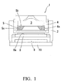
- FIG. 1 is a cross-sectional view showing a camera module 1 according to an embodiment of the present invention. Note that in the following description, the terms “upper” or “top” and “lower” or “bottom” are respectively used to denote the direction in FIG. 1 where a barrel 4 of a camera module 1 is located and the direction in FIG. 1 where a substrate 10 is located.
- the camera module 1 is composed from a housing 2 which constitutes an outer shell of the camera module 1; a lens unit 3 having an optical system of the camera module 1; a cylindrical barrel 4 made of a synthetic resin for holding the lens unit 3, the cylindrical barrel 4 having an inner circumferential surface 4a; a ring-shaped stopper 5 made of a synthetic resin through injection molding for fixing the lens unit 3 inside the barrel 4, the stopper 5 having an outer circumferential surface 5a; and an image pick-up device 9 provided below the lens unit 3.
- the stopper 5 has been formed from a stopper molded body 5A having a gate 5c produced during the injection molding process so as to protrude upwardly from a part of an upper surface of the stopper molded body 5A.
- the gate 5c is cut off from the stopper molded body 5A after the stopper molded body 5A has been removed from a die for injection molding to obtain the stopper 5.
- the entire of the outer circumferential surface 5a of the stopper 5 is in contact with the inner circumferential surface 4a of the barrel 4 without any gap therebetween.
- the housing 2 is a component having a roughly cubic shape and having a hollow space therein, and made of a synthetic resin material. Inside the hollow space of the housing, the barrel 4 (which will be described later in detail) is disposed.
- the barrel 4 is a cylindrical component made of a synthetic resin and having a hollow space therein. Inside the hollow space of the barrel 4, the lens unit 3 is provided, and a stopper (which will be described later in detail) 5 is also provided inside the hollow space below the lens unit 3.
- the lens unit 3 constitutes an optical system of the camera module 1.
- the stopper 5 is a ring-shaped member made of a synthetic resin material and formed by insulating molding. As described above, the stopper 5 is disposed at the lower side of the hollow space of the barrel 4. As shown in FIG. 2, the stopper 5 is formed from a stopper molded body 5A having a gate 5c which has been formed during the injection molding process. The gate 5c is formed on a part of the upper surface of the stopper molded body 5A so as to protrude upwardly therefrom, and the gate 5c is cut off from the stopper molded body 5A after the stopper molded body 5A has been removed from a die (not shown in the drawing) for the injection molding.
- the upper surface of the stopper 5 is formed with a depression or notch 5d around the base end of the gate 5c, which is depressed so as to be lower than the upper surface 5b of the stopper 5.
- the gate 5c is cut away at the base end thereof, whereby the stopper 5 is formed.
- FIG. 3 shows a state that the gate 5c is cut away from the stopper molded body 5A, that is, FIG. 3 shows the stopper 5.
- the thus formed stopper 5 is press-fitted into the barrel 4 from the bottom thereof so that the entire of the outer circumferential surface 5a of the stopper 5 is in contact with the inner circumferential surface 4a of the barrel 4 and the upper surface 5b of the stopper 5 is also in contact with the bottom of the lens unit 3. In this state, the stopper 5 is bonded with the barrel 4. In this way, the lens unit 3 is held inside the barrel 4 by the stopper 5.
- the reference numeral 9 denotes an image pick-up device disposed below the lens unit 3, and the image pick-up device 9 is mounted on the substrate 10.
- the reference numeral 8 denotes an IR cut filter having an upper surface 8a.
- the stopper 5 is formed from the stopper molded body 5A having the gate 5c which has been formed during the injection molding process.
- the gate 5c is formed on a part of the upper surface of the stopper molded body 5A so as to protrude upwardly therefrom.
- the gate 5c is cut off after the stopper molded body 5A has been removed from a die for injection molding to form the stopper 5 having a ring shape and having an outer circumferential surface 5a.
- the stopper 5 When the camera module 1 is assembled, the stopper 5 is press-fitted into the hollow space of the barrel 4 from the bottom thereof so that the entire outer circumferential surface 5a of the stopper 5 is in contact with the inner circumferential surface of the barrel 4 and the upper surface 5b of the stopper 5 is also in contact with the bottom of the lens unit 3. Therefore, no gap is created between the entire outer circumferential surface 5a of the stopper 5 and the inner circumferential surface 4a of the barrel 4.
- the depression 5d is formed at a position where the end portion of the gate 5c has been located.
- the depression 5d is formed so as to be lower than the upper surface 5b of the stopper 5. Therefore, there is no possibility that a remaining part of the gate 5c protrudes upwardly beyond the upper surface 5b of the stopper 5, and thus the upper surface 5b of the stopper 5 can be made close contact with the bottom of the lens unit 3.
Landscapes
- Physics & Mathematics (AREA)
- General Physics & Mathematics (AREA)
- Optics & Photonics (AREA)
- Studio Devices (AREA)
- Lens Barrels (AREA)
- Transforming Light Signals Into Electric Signals (AREA)
Abstract
Description
- The present invention relates to a camera module, and more particularly to a relatively small camera module to be mounted on an electronic apparatus such as a back monitor for a vehicle and a cellular phone and the like.
- A relatively small camera module is mounted on an electronic apparatus such as a cellular phone and the like. Such a camera module includes an image pick-up device such as a CMOS sensor or a CCD sensor. FIG. 4 is a cross-sectional view showing a
conventional camera module 100. Thecamera module 100 includes ahousing 101 which constitutes an outer shell of thecamera module 100, alens unit 102 having an optical system of thecamera module 100, acylindrical barrel 103 made of a synthetic resin for holding thelens unit 102, a ring-shaped stopper 104 made of a synthetic resin for fixing thelens unit 102 inside thebarrel 103, anIR cut filter 108 disposed below thelens unit 102, an image pick-up device 109 provided below theIR cut filter 108, and asubstrate 110 on which the image pick-up device 109 is mounted. - As shown in FIG. 5, the
stopper 104 is a ring-shaped member made of a synthetic resin, and it is formed by means of injection molding. In more details, thestopper 104 is formed from a stopper molded body having a gate (not shown in the drawing). Such a gate is necessarily formed for injecting a synthetic resin material into a mold die for thestopper 104, and it protrudes horizontally from a part of the outer circumferential surface of the stopper molded body. Thestopper 104 is obtained by cutting away the gate formed on the stopper molded body after the stopper molded body has been removed from a mold die for injection molding. Therefore, thestopper 104 thus obtained has acutting surface 104b at which the gate was formed, that is, a part of thestopper 104 has been cut away together with the gate and as a result of this thecutting surface 104b is formed. - The thus manufactured
stopper 104 is press-fitted into thebarrel 103 from the bottom thereof, and then the outercircumferential surface 104a of thestopper 104 other than thecutting surface 104b is bonded to the innercircumferential surface 103a of thebarrel 103. In this state, the upper surface of thestopper 104 is in contact with the bottom surface of thelens unit 102 so that thelens unit 102 is held inside thebarrel 103 by means of thestopper 104. - However, in the conventional camera module described above, a part of the
stopper 104 where thecutting surface 104b is formed is not bonded to the innercircumferential surface 103a of thebarrel 103, and thus there is a problem in that a gap is created between thecutting surface 104b and the innercircumferential surface 103a of thebarrel 103. - In the camera module described above, when the
stopper 104 is press-fitted into thebarrel 103 from the bottom thereof, the outercircumferential surface 104a of thestopper 104 is in friction with the inner circumferential surface of thebarrel 103. Therefore, there is a case that dust of the synthetic resin is produced due to the friction between the outercircumferential surface 104a of thestopper 104 and the innercircumferential surface 103a of thebarrel 103, and the thus produced dust may fall under thestopper 104 through thegap 107 and then adhere to the surface of theIR cut filter 108. If the dust adheres to the surface of theIR cut filter 108 through thegap 107, it becomes impossible to obtain a fine image by the image pick-up device 109. - The present invention has been made in view of the above problem. It is, therefore, an object of the present invention to provide a camera module which does not have any gap between an outer circumferential surface of a ring-shaped stopper and an inner circumferential surface of a barrel.
- In order to achieve the above object, the present invention is directed to a camera module which includes a housing which constitutes an outer shell of the camera module; a lens unit having an optical system of the camera module; a cylindrical barrel made of a synthetic resin for holding the lens unit, the cylindrical barrel having an inner circumferential surface; a ring-shaped stopper made of a synthetic resin through injection molding for fixing the lens unit inside the barrel, the stopper having an outer circumferential surface; and an image pick-up device provided below the lens unit. In this camera module, the stopper has been formed from a stopper molded body having a gate produced during the injection molding process so as to protrude upwardly from a part of an upper surface of the stopper molded body, and the gate is cut off from the stopper molded body after the stopper molded body has been removed from a die for injection molding to obtain the stopper. The entire of the outer circumferential surface of the thus formed stopper is in contact with the inner circumferential surface of the barrel without any gap therebetween.
- According to the camera module having the structure described above, since no gap is created between the entire outer circumferential surface of the stopper and the inner circumferential surface of the barrel, it is possible to prevent dust which may be produced by the friction between the outer circumferential surface of the stopper and the inner circumferential surface of the barrel when they are press-fitted from falling in the space inside the camera module and then adhering to the surface of the IR filter.
- In the camera module according to the present invention, it is preferred that the stopper has a depression in the upper surface thereof at a position where the base end of the gate was located.
- According to the structure described above, there is no possibility that a remaining part of the gate protrudes upwardly beyond the upper surface of the stopper, and thus the upper surface of the stopper can be made close contact with the bottom of the lens unit.
- The above and other objects, features, and advantages of the present invention will be apparent from the following description when taken in conjunction with the accompanying drawings which illustrate preferred embodiments of the present invention by way of example.
-
- FIG. 1 is a cross-sectional view showing a camera module according to an embodiment of the present invention;
- FIG. 2 is a perspective view of a stopper molded body 5A having a
gate 5c from which astopper 5 of the camera module shown in FIG. 1 is formed; - FIG. 3 is a perspective view of the
stopper 5 of the camera module shown in FIG. 1; - FIG. 4 is a cross-sectional view showing a conventional camera module; and
- FIG. 5 is a perspective view of a
stopper 104 for use in the camera module shown in FIG. 4. - A camera module according to an embodiment of the present invention will be described below with reference to FIGS. 1 to 3. FIG. 1 is a cross-sectional view showing a camera module 1 according to an embodiment of the present invention. Note that in the following description, the terms "upper" or "top" and "lower" or "bottom" are respectively used to denote the direction in FIG. 1 where a
barrel 4 of a camera module 1 is located and the direction in FIG. 1 where asubstrate 10 is located. - The camera module 1 is composed from a
housing 2 which constitutes an outer shell of the camera module 1; alens unit 3 having an optical system of the camera module 1; acylindrical barrel 4 made of a synthetic resin for holding thelens unit 3, thecylindrical barrel 4 having an innercircumferential surface 4a; a ring-shaped stopper 5 made of a synthetic resin through injection molding for fixing thelens unit 3 inside thebarrel 4, thestopper 5 having an outercircumferential surface 5a; and an image pick-up device 9 provided below thelens unit 3. As shown in FIG. 2, thestopper 5 has been formed from a stopper molded body 5A having agate 5c produced during the injection molding process so as to protrude upwardly from a part of an upper surface of the stopper molded body 5A. Thegate 5c is cut off from the stopper molded body 5A after the stopper molded body 5A has been removed from a die for injection molding to obtain thestopper 5. In the camera module 1 described above, the entire of the outercircumferential surface 5a of thestopper 5 is in contact with the innercircumferential surface 4a of thebarrel 4 without any gap therebetween. - In more details, the
housing 2 is a component having a roughly cubic shape and having a hollow space therein, and made of a synthetic resin material. Inside the hollow space of the housing, the barrel 4 (which will be described later in detail) is disposed. - The
barrel 4 is a cylindrical component made of a synthetic resin and having a hollow space therein. Inside the hollow space of thebarrel 4, thelens unit 3 is provided, and a stopper (which will be described later in detail) 5 is also provided inside the hollow space below thelens unit 3. Thelens unit 3 constitutes an optical system of the camera module 1. - The
stopper 5 is a ring-shaped member made of a synthetic resin material and formed by insulating molding. As described above, thestopper 5 is disposed at the lower side of the hollow space of thebarrel 4. As shown in FIG. 2, thestopper 5 is formed from a stopper molded body 5A having agate 5c which has been formed during the injection molding process. Thegate 5c is formed on a part of the upper surface of the stopper molded body 5A so as to protrude upwardly therefrom, and thegate 5c is cut off from the stopper molded body 5A after the stopper molded body 5A has been removed from a die (not shown in the drawing) for the injection molding. - As shown in FIG. 2, the upper surface of the
stopper 5 is formed with a depression ornotch 5d around the base end of thegate 5c, which is depressed so as to be lower than theupper surface 5b of thestopper 5. Thegate 5c is cut away at the base end thereof, whereby thestopper 5 is formed. FIG. 3 shows a state that thegate 5c is cut away from the stopper molded body 5A, that is, FIG. 3 shows thestopper 5. - The thus formed
stopper 5 is press-fitted into thebarrel 4 from the bottom thereof so that the entire of the outercircumferential surface 5a of thestopper 5 is in contact with the innercircumferential surface 4a of thebarrel 4 and theupper surface 5b of thestopper 5 is also in contact with the bottom of thelens unit 3. In this state, thestopper 5 is bonded with thebarrel 4. In this way, thelens unit 3 is held inside thebarrel 4 by thestopper 5. - Note that in FIG. 1 the reference numeral 9 denotes an image pick-up device disposed below the
lens unit 3, and the image pick-up device 9 is mounted on thesubstrate 10. Further, thereference numeral 8 denotes an IR cut filter having anupper surface 8a. - Hereinbelow, a description will be made with regard to the functions and advantages of the embodiment of the camera module 1 described above.
- In the embodiment described above, the
stopper 5 is formed from the stopper molded body 5A having thegate 5c which has been formed during the injection molding process. Thegate 5c is formed on a part of the upper surface of the stopper molded body 5A so as to protrude upwardly therefrom. Thegate 5c is cut off after the stopper molded body 5A has been removed from a die for injection molding to form thestopper 5 having a ring shape and having an outercircumferential surface 5a. When the camera module 1 is assembled, thestopper 5 is press-fitted into the hollow space of thebarrel 4 from the bottom thereof so that the entire outercircumferential surface 5a of thestopper 5 is in contact with the inner circumferential surface of thebarrel 4 and theupper surface 5b of thestopper 5 is also in contact with the bottom of thelens unit 3. Therefore, no gap is created between the entire outercircumferential surface 5a of thestopper 5 and the innercircumferential surface 4a of thebarrel 4. With this structure, it is possible to prevent dust which may be produced by the friction between the outercircumferential surface 5a of thestopper 5 and the innercircumferential surface 4a of thebarrel 4 when they are press-fitted from falling in the space inside the camera module 1 and then adhering on thesurface 8a of theIR filter 8. - Further, in the camera module 1 of the embodiment described above, the
depression 5d is formed at a position where the end portion of thegate 5c has been located. Thedepression 5d is formed so as to be lower than theupper surface 5b of thestopper 5. Therefore, there is no possibility that a remaining part of thegate 5c protrudes upwardly beyond theupper surface 5b of thestopper 5, and thus theupper surface 5b of thestopper 5 can be made close contact with the bottom of thelens unit 3. - Finally, it should be understood that the present invention is not limited to the preferred embodiment described hereinabove and, needless to say, a variety of modifications or variations may be made without departing from the scope of the invention defined in the following claims.
Claims (2)
- A camera module (1), comprising:a housing (2) which constitutes an outer shell of the camera module (1);a lens unit (3) having an optical system of the camera module (1);a cylindrical barrel (4) made of a synthetic resin for holding the lens unit (3), the cylindrical barrel (4) having an inner circumferential surface (4a);a ring-shaped stopper (5) made of a synthetic resin through injection molding for fixing the lens unit (3) inside the barrel (4), the stopper (5) having an outer circumferential surface (5a); andan image pick-up device (9) provided below the lens unit (3);CHARACTERIZED IN THAT the stopper (5) has been formed from a stopper molded body (5A) having a gate (5c) produced during the injection molding process so as to protrude upwardly from a part of an upper surface of the stopper molded body (5A), and the gate (5c) is cut off from the stopper molded body (5A) after the stopper molded body has been removed from a die for injection molding to obtain the stopper (5), wherein the entire of the outer circumferential surface (5a) of the stopper (5) is in contact with the inner circumferential surface (4a) of the barrel (4) without any gap therebetween.
- The camera module (1) as claimed in claim 1, wherein the stopper (5) has a depression (5d) in the upper surface (5b) thereof at a position where the base end of the gate (5c) was located.
Applications Claiming Priority (1)
| Application Number | Priority Date | Filing Date | Title |
|---|---|---|---|
| JP2005378878A JP2007181043A (en) | 2005-12-28 | 2005-12-28 | The camera module |
Publications (2)
| Publication Number | Publication Date |
|---|---|
| EP1804097A1 true EP1804097A1 (en) | 2007-07-04 |
| EP1804097B1 EP1804097B1 (en) | 2010-02-10 |
Family
ID=37963756
Family Applications (1)
| Application Number | Title | Priority Date | Filing Date |
|---|---|---|---|
| EP06127232A Not-in-force EP1804097B1 (en) | 2005-12-28 | 2006-12-27 | Method of forming a ring shaped stopper for use in a camera |
Country Status (3)
| Country | Link |
|---|---|
| EP (1) | EP1804097B1 (en) |
| JP (1) | JP2007181043A (en) |
| DE (1) | DE602006012164D1 (en) |
Cited By (1)
| Publication number | Priority date | Publication date | Assignee | Title |
|---|---|---|---|---|
| CN103458160A (en) * | 2012-06-01 | 2013-12-18 | A&P克里比茨株式会社 | Connector-integrated camera for vehicle and manufacturing method thereof |
Families Citing this family (1)
| Publication number | Priority date | Publication date | Assignee | Title |
|---|---|---|---|---|
| WO2021000128A1 (en) * | 2019-06-29 | 2021-01-07 | 瑞声光学解决方案私人有限公司 | Lens module |
Citations (4)
| Publication number | Priority date | Publication date | Assignee | Title |
|---|---|---|---|---|
| US20020001137A1 (en) * | 2000-06-28 | 2002-01-03 | Asahi Kogaku Kogyo Kabushiki Kaisha | Lens moving device |
| EP1429168A2 (en) * | 2002-12-13 | 2004-06-16 | Konica Minolta Holdings, Inc. | Image sensing device and portable terminal |
| EP1465411A2 (en) * | 2003-03-31 | 2004-10-06 | Mitsumi Electric Co., Ltd. | Compact camera module |
| EP1484636A1 (en) * | 1999-11-26 | 2004-12-08 | Fuji Photo Film Co., Ltd. | Diaphragm control in a lens-fitted photo film unit |
Family Cites Families (8)
| Publication number | Priority date | Publication date | Assignee | Title |
|---|---|---|---|---|
| JPH0419491A (en) * | 1990-05-11 | 1992-01-23 | Furoueru:Kk | Tube fitting |
| JP3692670B2 (en) * | 1996-12-10 | 2005-09-07 | フジノン株式会社 | Endoscope lens device |
| JP2003025379A (en) * | 2001-07-11 | 2003-01-29 | Nakanishi Metal Works Co Ltd | Manufacturing method of precision resin product and seal for bearing |
| JP4269334B2 (en) * | 2002-10-28 | 2009-05-27 | コニカミノルタホールディングス株式会社 | Imaging lens, imaging unit, and portable terminal |
| JP2005070505A (en) * | 2003-08-26 | 2005-03-17 | Auto Network Gijutsu Kenkyusho:Kk | Camera device |
| DE10344770A1 (en) * | 2003-09-26 | 2005-05-04 | Siemens Ag | Optical module and optical system |
| JP4234626B2 (en) * | 2004-03-08 | 2009-03-04 | 株式会社長野光学研究所 | Shooting camera |
| JP2005347837A (en) * | 2004-05-31 | 2005-12-15 | Canon Inc | Imaging apparatus and electronic apparatus |
-
2005
- 2005-12-28 JP JP2005378878A patent/JP2007181043A/en active Pending
-
2006
- 2006-12-27 DE DE602006012164T patent/DE602006012164D1/en active Active
- 2006-12-27 EP EP06127232A patent/EP1804097B1/en not_active Not-in-force
Patent Citations (4)
| Publication number | Priority date | Publication date | Assignee | Title |
|---|---|---|---|---|
| EP1484636A1 (en) * | 1999-11-26 | 2004-12-08 | Fuji Photo Film Co., Ltd. | Diaphragm control in a lens-fitted photo film unit |
| US20020001137A1 (en) * | 2000-06-28 | 2002-01-03 | Asahi Kogaku Kogyo Kabushiki Kaisha | Lens moving device |
| EP1429168A2 (en) * | 2002-12-13 | 2004-06-16 | Konica Minolta Holdings, Inc. | Image sensing device and portable terminal |
| EP1465411A2 (en) * | 2003-03-31 | 2004-10-06 | Mitsumi Electric Co., Ltd. | Compact camera module |
Cited By (1)
| Publication number | Priority date | Publication date | Assignee | Title |
|---|---|---|---|---|
| CN103458160A (en) * | 2012-06-01 | 2013-12-18 | A&P克里比茨株式会社 | Connector-integrated camera for vehicle and manufacturing method thereof |
Also Published As
| Publication number | Publication date |
|---|---|
| DE602006012164D1 (en) | 2010-03-25 |
| EP1804097B1 (en) | 2010-02-10 |
| JP2007181043A (en) | 2007-07-12 |
Similar Documents
| Publication | Publication Date | Title |
|---|---|---|
| RU2476913C2 (en) | Camera module | |
| JPWO2016017682A1 (en) | IMAGING DEVICE, OPTICAL DEVICE, ELECTRONIC DEVICE, VEHICLE, AND IMAGING DEVICE MANUFACTURING METHOD | |
| US7196857B2 (en) | Image pickup module, method of manufacturing the same, and spacer with infrared ray cut film | |
| US7660057B2 (en) | Lens assembly and imaging apparatus | |
| US20080131113A1 (en) | Camera housing with a view lens, method for making the camera housing, and camera using the housing | |
| CN113194219B (en) | Camera module | |
| JP2007006475A (en) | Camera module for mobile communication device | |
| US6940058B2 (en) | Injection molded image sensor module | |
| US8203647B2 (en) | Image sensor module and method for manufacturing the same | |
| CN110389482B (en) | Annular optical element and imaging lens | |
| US7914159B2 (en) | Method for manufacturing lens using opaque or semi-opaque material | |
| CN111492410A (en) | Card type intelligent key | |
| CN102914846B (en) | Electronic device and adopted lens module | |
| US8737051B2 (en) | Display seal for electronic device | |
| CN111083342A (en) | Camera module and electronic product | |
| JP2006293100A (en) | Camera module assembly method and camera module | |
| CN113194218A (en) | Camera module manufacturing method and electronic product manufacturing method | |
| EP1804097B1 (en) | Method of forming a ring shaped stopper for use in a camera | |
| WO2014156503A1 (en) | Optical lens, mold, lens unit, and image capture device | |
| JP2000147320A (en) | Ferrule for optical connector and method and apparatus for manufacturing the same | |
| JP2005300690A (en) | Lens unit | |
| CN212572680U (en) | Camera module | |
| EP1804117A1 (en) | Camera module | |
| JP3977104B2 (en) | Solid-state imaging device and manufacturing method thereof | |
| TWI816244B (en) | Lens modules and electronics |
Legal Events
| Date | Code | Title | Description |
|---|---|---|---|
| PUAI | Public reference made under article 153(3) epc to a published international application that has entered the european phase |
Free format text: ORIGINAL CODE: 0009012 |
|
| AK | Designated contracting states |
Kind code of ref document: A1 Designated state(s): AT BE BG CH CY CZ DE DK EE ES FI FR GB GR HU IE IS IT LI LT LU LV MC NL PL PT RO SE SI SK TR |
|
| AX | Request for extension of the european patent |
Extension state: AL BA HR MK YU |
|
| 17P | Request for examination filed |
Effective date: 20071221 |
|
| AKX | Designation fees paid |
Designated state(s): DE FI FR GB |
|
| 17Q | First examination report despatched |
Effective date: 20080214 |
|
| GRAP | Despatch of communication of intention to grant a patent |
Free format text: ORIGINAL CODE: EPIDOSNIGR1 |
|
| RTI1 | Title (correction) |
Free format text: METHOD OF FORMING A RING SHAPED STOPPER FOR USE IN A CAMERA |
|
| GRAS | Grant fee paid |
Free format text: ORIGINAL CODE: EPIDOSNIGR3 |
|
| GRAA | (expected) grant |
Free format text: ORIGINAL CODE: 0009210 |
|
| AK | Designated contracting states |
Kind code of ref document: B1 Designated state(s): DE FI FR GB |
|
| REG | Reference to a national code |
Ref country code: GB Ref legal event code: FG4D |
|
| REF | Corresponds to: |
Ref document number: 602006012164 Country of ref document: DE Date of ref document: 20100325 Kind code of ref document: P |
|
| PG25 | Lapsed in a contracting state [announced via postgrant information from national office to epo] |
Ref country code: FI Free format text: LAPSE BECAUSE OF FAILURE TO SUBMIT A TRANSLATION OF THE DESCRIPTION OR TO PAY THE FEE WITHIN THE PRESCRIBED TIME-LIMIT Effective date: 20100210 |
|
| PLBE | No opposition filed within time limit |
Free format text: ORIGINAL CODE: 0009261 |
|
| STAA | Information on the status of an ep patent application or granted ep patent |
Free format text: STATUS: NO OPPOSITION FILED WITHIN TIME LIMIT |
|
| 26N | No opposition filed |
Effective date: 20101111 |
|
| PGFP | Annual fee paid to national office [announced via postgrant information from national office to epo] |
Ref country code: GB Payment date: 20101112 Year of fee payment: 5 |
|
| PGFP | Annual fee paid to national office [announced via postgrant information from national office to epo] |
Ref country code: DE Payment date: 20110224 Year of fee payment: 5 |
|
| REG | Reference to a national code |
Ref country code: FR Ref legal event code: ST Effective date: 20110831 |
|
| PG25 | Lapsed in a contracting state [announced via postgrant information from national office to epo] |
Ref country code: FR Free format text: LAPSE BECAUSE OF NON-PAYMENT OF DUE FEES Effective date: 20110103 |
|
| GBPC | Gb: european patent ceased through non-payment of renewal fee |
Effective date: 20111227 |
|
| REG | Reference to a national code |
Ref country code: DE Ref legal event code: R119 Ref document number: 602006012164 Country of ref document: DE Effective date: 20120703 |
|
| PG25 | Lapsed in a contracting state [announced via postgrant information from national office to epo] |
Ref country code: DE Free format text: LAPSE BECAUSE OF NON-PAYMENT OF DUE FEES Effective date: 20120703 Ref country code: GB Free format text: LAPSE BECAUSE OF NON-PAYMENT OF DUE FEES Effective date: 20111227 |