EP1550893A1 - Lens unit and electronic apparatus using the same - Google Patents
Lens unit and electronic apparatus using the same Download PDFInfo
- Publication number
- EP1550893A1 EP1550893A1 EP04030426A EP04030426A EP1550893A1 EP 1550893 A1 EP1550893 A1 EP 1550893A1 EP 04030426 A EP04030426 A EP 04030426A EP 04030426 A EP04030426 A EP 04030426A EP 1550893 A1 EP1550893 A1 EP 1550893A1
- Authority
- EP
- European Patent Office
- Prior art keywords
- lens
- holder
- holding portion
- lens unit
- inner periphery
- Prior art date
- Legal status (The legal status is an assumption and is not a legal conclusion. Google has not performed a legal analysis and makes no representation as to the accuracy of the status listed.)
- Withdrawn
Links
Images


Classifications
-
- G—PHYSICS
- G02—OPTICS
- G02B—OPTICAL ELEMENTS, SYSTEMS OR APPARATUS
- G02B7/00—Mountings, adjusting means, or light-tight connections, for optical elements
- G02B7/02—Mountings, adjusting means, or light-tight connections, for optical elements for lenses
-
- G—PHYSICS
- G02—OPTICS
- G02B—OPTICAL ELEMENTS, SYSTEMS OR APPARATUS
- G02B13/00—Optical objectives specially designed for the purposes specified below
Definitions
- the present invention relates to a lens unit having at least two lenses housed in a cylindrical holder, and an electronic apparatus using the same.
- a portable telephone is equipped with a lens unit, enhancing its function.
- a lens unit is improved in aberration by housing a plurality of combined lenses in a cylindrical holder.
- a first lens having a top that functions as a lens is combined with a second lens, and housed in a cylindrical holder.
- the first lens and the second lens are combined and integrated, but the combined structure is disposed in spaced positional relation with the cylindrical holder. Therefore, the holder is axially deflected from the combined structure of the first lens and the second lens, and there arises a problem of lowering in aberration improving effect.
- a prior technology related to this application is, for example, introduced in Japanese Patent Laid-Open Application No. 2002-286987.
- the present invention is intended to enhance the aberration improving effect of a lens unit.
- a lens unit of the present invention comprises a cylindrical holder, a first lens and a second lens housed in the holder, wherein the first lens is cylindrical having a top that functions as a lens, and the second lens is pressed into the cylinder of the first lens having a top in such manner that the inner periphery of the first lens cylinder is pressed outwardly of the circumference. Since the first lens and the second lens are integrated with the cylindrical holder, the lens aberration may be improved due to the combination of at least these two lenses.
- the lens unit of the present invention comprises a cylindrical holder, a first lens and a second lens housed in the cylindrical holder, wherein the first lens is cylindrical having a top made of resin that functions as a lens, and the second lens made of glass is pressed into the cylinder of the first lens having a top in such manner that the inner periphery of the first lens cylinder is pressed outwardly of the circumference by the outer periphery of the second lens. Since the first lens and the second lens are integrated with the cylindrical holder, the lens aberration may be improved due to the combination of at least two lenses.
- the first lens is made of resin and the second lens is made of glass
- the second lens is harder than the first lens, and thereby, when the second lens is pressed into the cylinder of the first lens, the inner periphery of the first lens cylinder is deformed, making the job easier, and also the second lens pressed therein can be reliably held.
- the lens unit of the present invention comprises a cylindrical holder, a first lens and a second lens housed in the cylindrical holder, wherein the first lens is cylindrical having a top that functions as a lens, and the second lens is pressed into the cylinder of the first lens having a top in such manner that the inner periphery of the first lens cylinder is pressed outwardly of the circumference by the outer periphery of the second lens.
- the cylinder portion of the first lens is higher in hardness than the holding portion of the holder. Since the first lens and the second lens are integrated with the cylindrical holder, the lens aberration may be improved due to the combination of at least these two lenses.
- the cylinder portion of the first lens is higher in hardness than the holding portion of the holder, when the outer periphery of the first lens cylinder is pressed into the inner periphery of the holder and is resiliently held, the holding portion of the holder is easily deformed, making it possible to suppress the deformation of the first lens cylinder and the lens portion connecting thereto.
- the lens unit of the present invention is configured in that the inner periphery of the holder is provided with a cylindrical holding portion disposed at a predetermined distance from the inner periphery of the holder, and the outer periphery of the first lens cylinder is resiliently held by the inner periphery of the holding portion. Since the cylinder of the first lens is resiliently held by the holding portion of the holder, the first lens and the second lens can be held at a fixed position in the holder.
- the lens unit of the present invention is configured in that the holding portion of the holder is shaped so as to be resiliently increased in diameter, and also, the inner periphery of the holding portion is smaller in diameter than the outer periphery of the first lens cylinder. As the first lens cylinder is pressed into the holding portion of the holder, the first lens can be resiliently held at a fixed position in the holding portion of the holder.
- the lens unit of the present invention is configured in that the holder and the first lens are made of resin, and also, the holding portion of the holder is less in thickness than the cylindrical portion of the first lens. Since the holding portion of the holder is less in thickness than the cylindrical portion of the first lens, when the outer periphery of the first lens cylinder is pressed into the inner periphery of the holder and is resiliently held, the holding portion of the holder is easily deformed, making it possible to lessen the deformation of the first lens cylinder and the lens connecting thereto.
- the lens unit of the present invention comprises a first lens made of resin and a second lens made of glass. Because of this combination, the second lens is harder than the first lens. When the second lens is pressed into the cylindrical portion of the first lens, the inner periphery of the first lens cylinder is deformed, making the job easier, and the second lens pressed therein can be reliably held.
- the lens unit of the present invention is configured in that at least one of the inner surface of the holding portion of the holder and the outer periphery of the cylinder of the first lens is roughened. Since at least one of the inner surface of the holding portion of the holder and the outer periphery of the first lens cylinder is roughened, when the outer periphery of the first lens cylinder is pressed into the inner periphery of the holding portion of the holder, the inner periphery and the outer periphery bite into each other, and thereby, the first lens can be reliably held by the holding portion.
- the lens unit of the present invention is configured in that the cylinder of the first lens is higher in hardness than the holding portion of the holder. Since the cylinder of the first lens is higher in hardness than the holding portion of the holder, when the outer periphery of the first lens cylinder is pressed into the inner periphery of the holder and is resiliently held, the holding portion of the holder is easily deformed. Accordingly, it is possible to lessen the deformation of the first lens cylinder and the lens connecting thereto.
- the lens unit of the present invention is configured in that at least one of the inner surface of the holding portion of the holder and the outer periphery of the cylinder of the first lens is roughened. Since at least one of the inner surface of the holding portion of the holder and the outer periphery of the first lens cylinder is roughened, when the outer periphery of the first lens cylinder is pressed into the inner periphery of the holding portion of the holder, the inner periphery and the outer periphery bite into each other, and thereby, the first lens can be reliably held by the holding portion.
- the lens unit of the present invention comprises a first lens made of resin and a second lens made of glass. Because of this combination, the second lens is harder than the first lens, and when the second lens is pressed into the cylinder of the first lens, the inner periphery of the first lens cylinder is deformed, making the job easier, and the second lens pressed therein can be reliably held.
- the lens unit of the present invention is configured in that the second lens is harder than the first lens. Since the second lens is harder than the first lens, when the second lens is pressed into the cylinder of the first lens, the inner periphery of the first lens cylinder is deformed, making the job easier, and the second lens pressed therein can be reliably held.
- the lens unit of the present invention is configured in that the inner periphery of the first lens cylinder is in tight contact with the outer periphery of the second lens.
- the space between the first lens and the second lens can be substantially sealed up. Accordingly, it is possible to prevent the first lens made of resin from being deteriorated due to moisture in the air that might be otherwise intruded into the space.
- the lens unit of the present invention is configured in that a flange inwardly extending from the inner periphery of the holding portion of the holder is integrated with one end of the holding portion of the holder, and the lens portion of the first lens is inserted into the holding portion from one end of the holding portion of the holder. Also, a collar outwardly extended toward the inner periphery of the holder at a portion outside the holding portion of the first lens cylinder is abutted on the flange of the holding portion of the holder. When the first lens is inserted into the holding portion of the holder, the collar of the first lens is abutted on the flange of the holding portion of the holder, and thereby, the position of the first lens in the holder can be stabilized.
- the lens unit of the present invention is configured in that at one end of the inner periphery of the holder is disposed a cylindrical throttle member which presses the collar of the first lens against the flange of the holding portion.
- the cylindrical throttle member is fitted at one end of the inner periphery of the holder, and thereby, the collar of the first lens is abutted on the flange of the holding portion, enabling the positioning in the holder of the first lens.
- the lens unit of the present invention is configured in that the throttle member is provided with a pressing portion which presses the second lens into the cylinder of the first lens.
- the throttle member fitted at one end of the inner periphery of the holder, positioning of the first lens in the holder and positioning of the second lens in the cylinder of the first lens can be easily performed.
- the lens unit of the present invention is configured in that the abutment of the inner periphery of the cylinder of the first lens and the outer periphery of the second lens is closer to the collar than the abutment of the flange and collar.
- the outer periphery of the second lens comes in contact with the inner periphery of the first lens cylinder, deforming the first lens outwardly, then only the collar is widened outwardly, and thereby, the lens is easily deformed, improving the workability.
- the lens unit of the present invention is configured in that the inner periphery of the first lens cylinder is sloped so as to become smaller in diameter from the collar side toward the lens side. Since the inner periphery of the lens cylinder is given a slope so as to be smaller in diameter from the collar side toward the lens side, when the second lens is pressed into the cylinder of the first lens by the throttle member, it comes into contact with the slope, and the second lens can be installed at a fixed position.
- the lens unit of the present invention is configured in that the portion coming in contact with the pressing portion of the throttle member of the second lens is plane. Since the second lens portion coming in contact with the pressing portion of the throttle member is plane, when the second lens is pressed into the cylinder of the first lens by the throttle member, the second lens is subjected to a nearly uniform pressure over its entire periphery and is appropriately press-fitted therein.
- an electronic apparatus of the present invention comprises a main body case, a lens unit disposed in the main body case, and an image pickup element disposed in the main body case opposing to the lens unit. Also, the lens unit is disposed so that the lens side of the first lens is opposed to the image pickup element in the main body case. Proper image forming can be realized by the lens unit with the first lens and the second lens integrated.
- the electronic apparatus of the present invention is configured in that the throttle member surface of the lens unit is covered with a transparent cover. In this configuration, it is possible to eliminate such trouble that an excessive force is applied to the throttle member outside the main body case, causing the first lens to be excessively pushed and damaged by the throttle member.
- the electronic apparatus of the present invention is configured in that the lens unit is housed in the main body case, and the throttle member surface of the lens unit is not projected from the main body case surface. Since the throttle member of the lens unit is not protruded from the main body case, it is possible to prevent the first lens from being excessively pushed and damaged by the throttle member due to an excessive force applied from the main body case to the throttle member.
- an electronic apparatus of the present invention comprises a main body case, a lens unit disposed in the main body case, and an image pickup element disposed in the main body case opposing to the lens unit.
- the lens unit is disposed so that the lens side of the first lens is opposed to the image pickup element in the main body case, and proper image forming can be realized by the lens unit with the first lens and the second lens integrated.
- the electronic apparatus of the present invention is configured in that the throttle member surface of the lens unit is covered with a transparent cover. In this configuration, it is possible to eliminate such problem that an excessive force is applied to the throttle member outside the main body case, causing the first lens to be excessively pushed and damaged by the throttle member.
- the electronic apparatus of the present invention is configured in that the lens unit is housed in the main body case, and the throttle member surface of the lens unit is not protruded from the main body case surface. Since the throttle member of the lens unit is not protruded from the main body case, it is possible to eliminate such trouble that an excessive force is applied to the throttle member outside the main body case, causing the first lens to be excessively pushed and damaged by the throttle member.
- an electronic apparatus of the present invention comprises a main body case, a lens unit disposed in the main body case, and an image pickup element disposed in the main body case opposing to the lens unit. Also, the lens side of the lens unit is disposed so as to be opposed to the image pickup element in the main body case. Proper image forming can be realized by the lens unit with the first lens and the second lens integrated.
- the electronic apparatus of the present invention is configured in that the throttle member surface of the lens unit is covered with a transparent cover. In this configuration, it is possible to prevent such trouble that an excessive force is applied to the throttle member outside the main body case, causing the first lens to be excessively pushed and damaged by the throttle member.
- the electronic apparatus of the present invention is configured in that the lens unit is housed in the main body case, and the throttle member surface of the lens unit is not projected from the main body case surface. Since the throttle member of the lens unit is not protruded from the main body case, it is possible to prevent such trouble that an excessive force is applied from the main body case to the throttle member, causing the first lens to be excessively pushed and damaged by the throttle member.
- a lens unit in the present preferred embodiment comprises cylindrical holder 1, for example, made of resin such as polycarbonate, first lens 2, second lens 3, and third lens 4 which are housed in holder 1.
- First lens 2 is for example made of transparent resin, and its top is formed of lens portion 2a, which is cylindrical having a top.
- Cylindrical second lens 3 made of glass is pressed into cylinder 2b of cylindrical first lens 2 having a top in such manner that the inner periphery of cylinder 2b of first lens 2 is pressed outwardly of the circumference by the outer periphery of second lens 3.
- cylindrical holding portion 1a spaced a predetermined distance from the inner periphery of holder 1, and the outer periphery of cylinder 2b of first lens 2 is resiliently held by the inner periphery of holding portion 1a.
- first lens 2 is resiliently held by holding portion 1a of holder 1, and thereby, the first lens 2 and second lens 3 are held at a fixed position in holder 1.
- Holding portion 1a of holder 1 is resiliently diametrically expandable, that is, formed from a resilient material, and its diameter is free to increase and decrease, and also, the inner peripheral diameter of holding portion 1a is smaller than the outer peripheral diameter of cylinder 2b of first lens 2. Accordingly, in straight view of Fig. 3, pressing the cylinder 2b of first lens 2 into holding portion 1a of holder 1 from above, first lens 2 can be resiliently held at a fixed position in holding portion 1a of holder 1.
- resin is used as the material for holder 1 and first lens 2, and holding portion 1a of holder 1 is less in thickness than cylinder 2b of first lens 2 as shown in Fig. 3.
- holding portion 1a of holder 1 is less in thickness than cylinder 2b of first lens 2, when the outer periphery of cylinder 2b of first lens 2 is pressed into the inner periphery of holder 1 and is resiliently held, holding portion 1a of holder 1 is easily deformed. Accordingly, the deformation of cylinder 2b of first lens 2 and lens portion 2a connecting thereto can be lessened, and it is preferable as optical characteristic.
- Second lens 3 is an aspherical lens, and the second lens 3 is pressed into cylinder 2b of first lens 2 by throttle member 5.
- cylindrical throttle member 5 made of resin such as polycarbonate is provided with pressing portion 5a which presses second lens 3 into cylinder 2b of first lens 2 and pressing portion 5b which presses first lens 2 already installed.
- second lens 3 is made of glass and first lens 2 is made of resin, and this is one of the characteristics of the present invention.
- second lens 3 is made of glass, and first lens 2 is made of resin, and thereby, it is possible to make second lens 3 harder than first lens 2.
- second lens 3 is pressed into cylinder 2b of first lens 2, the inner periphery of cylinder 2b of first lens 2 is deformed, making the job easier, and also, second lens 3 pressed therein can be reliably held.
- first lens 2 is made of resin
- second lens 3 is made of glass, making the lenses different in hardness and causing cylinder 2b of first lens 2 to be deformed, and thereby, the inner periphery of cylinder 2b of first lens 2 comes in tight contact with the outer periphery of second lens 3.
- first lens 2 made of resin from being deteriorated due to moisture in the air that might be otherwise intruded into the space.
- the following configuration is effective for making the inner periphery of cylinder 2b of first lens 2 come in tight contact with the outer periphery of second lens 3. That is, the inner periphery of cylinder 2b of first lens 2 is sloped so as to be decreased in diameter from collar 2c toward lens portion 2a.
- flange 1b inwardly extended from the inner periphery of holding portion 1a of holder 1.
- Lens portion 2a of first lens 2 is inserted into holding portion 1a from one end of holding portion 1a of holder 1, and collar 2c outwardly extended toward the inner periphery of holder 1 at a portion outside the holding portion of cylinder 2b of first lens 2 is abutted on flange 1b of holding portion 1a of holder 1.
- first lens 2 when first lens 2 is inserted into holding portion 1a of holder 1, collar 2c of first lens 2 is abutted on flange 1b of holding portion 1a of holder 1, and thereby, first lens 2 can be reliably held in holder 1.
- the especially important point is that the abutment of the inner periphery of cylinder 2b of first lens 2 and the outer periphery of second lens 3 is closer to the collar 2c side than the abutment of flange 1b and collar 2c.
- the optical axis 7 first lens 2, second lens 3 and third lens 4 can be aligned in holder 1.
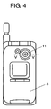
- lens units shown in Fig. 1 to Fig. 3 are mounted in main body case 8 of a portable telephone shown as an example of electronic apparatus as shown in Fig. 4 and Fig. 5.
- lens portion 2a of first lens 2 is opposed to image pickup element 10 in main body case 8, proper image forming can be realized by a lens unit with first lens 2, second lens 3 and third lens 4 integrated.
- the lens unit is housed in main body case 8, and the surface of throttle member 5 of the lens unit is not protruded from the surface of main body case 8.
- throttle member 5 of the lens unit is not protruded from main body case 8, it is possible to prevent excessive forces from being applied to throttle member 5 from outside main body case 8. Thus, first lens 2 can be prevented from being excessively pushed and damaged by throttle member 5.
- throttle member 5 of the lens unit since the surface of throttle member 5 of the lens unit is covered with transparent cover 11, application of excessive forces to throttle member 5 can be avoided outside the main body case 8, and therefore, it is possible to eliminate such trouble that first lens 2 is excessively pushed and damaged by throttle member 5.
- Fig. 5 same components and portions as those in Fig. 3 are given same reference numerals. Also the one shown in Fig. 5 comprises infrared ray cutting filter 9, image pickup element (charge coupled element) 10, transparent cover 11, and lens unit fixture 12.
- image pickup element charge coupled element
- the lens unit of the present invention is configured in that the first lens and the second lens are integrated in a holder together with a cylindrical holder. Accordingly, due to the combination of the first and second lenses at least, the lens aberration is improved, and the image pickup effect is enhanced in various electronic apparatuses.
Landscapes
- Physics & Mathematics (AREA)
- General Physics & Mathematics (AREA)
- Optics & Photonics (AREA)
- Lens Barrels (AREA)
- Studio Devices (AREA)
- Eyeglasses (AREA)
Abstract
Description
- The present invention relates to a lens unit having at least two lenses housed in a cylindrical holder, and an electronic apparatus using the same.
- As a recent trend, a portable telephone is equipped with a lens unit, enhancing its function. Such a lens unit is improved in aberration by housing a plurality of combined lenses in a cylindrical holder. For example, a first lens having a top that functions as a lens is combined with a second lens, and housed in a cylindrical holder.
- Conventionally, there has been a fear in this type of lens unit such that the cylindrical holder is axially deflected from the combined structure of the first lens and the second lens.
- For example, the first lens and the second lens are combined and integrated, but the combined structure is disposed in spaced positional relation with the cylindrical holder. Therefore, the holder is axially deflected from the combined structure of the first lens and the second lens, and there arises a problem of lowering in aberration improving effect.
- A prior technology related to this application is, for example, introduced in Japanese Patent Laid-Open Application No. 2002-286987.
- The present invention is intended to enhance the aberration improving effect of a lens unit.
- In order to achieve the purpose, a lens unit of the present invention comprises a cylindrical holder, a first lens and a second lens housed in the holder, wherein the first lens is cylindrical having a top that functions as a lens, and the second lens is pressed into the cylinder of the first lens having a top in such manner that the inner periphery of the first lens cylinder is pressed outwardly of the circumference. Since the first lens and the second lens are integrated with the cylindrical holder, the lens aberration may be improved due to the combination of at least these two lenses.
- Also, the lens unit of the present invention comprises a cylindrical holder, a first lens and a second lens housed in the cylindrical holder, wherein the first lens is cylindrical having a top made of resin that functions as a lens, and the second lens made of glass is pressed into the cylinder of the first lens having a top in such manner that the inner periphery of the first lens cylinder is pressed outwardly of the circumference by the outer periphery of the second lens. Since the first lens and the second lens are integrated with the cylindrical holder, the lens aberration may be improved due to the combination of at least two lenses.
- Also, since the first lens is made of resin and the second lens is made of glass, the second lens is harder than the first lens, and thereby, when the second lens is pressed into the cylinder of the first lens, the inner periphery of the first lens cylinder is deformed, making the job easier, and also the second lens pressed therein can be reliably held.
- Further, the lens unit of the present invention comprises a cylindrical holder, a first lens and a second lens housed in the cylindrical holder, wherein the first lens is cylindrical having a top that functions as a lens, and the second lens is pressed into the cylinder of the first lens having a top in such manner that the inner periphery of the first lens cylinder is pressed outwardly of the circumference by the outer periphery of the second lens. Also, the cylinder portion of the first lens is higher in hardness than the holding portion of the holder. Since the first lens and the second lens are integrated with the cylindrical holder, the lens aberration may be improved due to the combination of at least these two lenses.
- Also, since the cylinder portion of the first lens is higher in hardness than the holding portion of the holder, when the outer periphery of the first lens cylinder is pressed into the inner periphery of the holder and is resiliently held, the holding portion of the holder is easily deformed, making it possible to suppress the deformation of the first lens cylinder and the lens portion connecting thereto.
- Further, the lens unit of the present invention is configured in that the inner periphery of the holder is provided with a cylindrical holding portion disposed at a predetermined distance from the inner periphery of the holder, and the outer periphery of the first lens cylinder is resiliently held by the inner periphery of the holding portion. Since the cylinder of the first lens is resiliently held by the holding portion of the holder, the first lens and the second lens can be held at a fixed position in the holder.
- Also, the lens unit of the present invention is configured in that the holding portion of the holder is shaped so as to be resiliently increased in diameter, and also, the inner periphery of the holding portion is smaller in diameter than the outer periphery of the first lens cylinder. As the first lens cylinder is pressed into the holding portion of the holder, the first lens can be resiliently held at a fixed position in the holding portion of the holder.
- Further, the lens unit of the present invention is configured in that the holder and the first lens are made of resin, and also, the holding portion of the holder is less in thickness than the cylindrical portion of the first lens. Since the holding portion of the holder is less in thickness than the cylindrical portion of the first lens, when the outer periphery of the first lens cylinder is pressed into the inner periphery of the holder and is resiliently held, the holding portion of the holder is easily deformed, making it possible to lessen the deformation of the first lens cylinder and the lens connecting thereto.
- Also, the lens unit of the present invention comprises a first lens made of resin and a second lens made of glass. Because of this combination, the second lens is harder than the first lens. When the second lens is pressed into the cylindrical portion of the first lens, the inner periphery of the first lens cylinder is deformed, making the job easier, and the second lens pressed therein can be reliably held.
- Further, the lens unit of the present invention is configured in that at least one of the inner surface of the holding portion of the holder and the outer periphery of the cylinder of the first lens is roughened. Since at least one of the inner surface of the holding portion of the holder and the outer periphery of the first lens cylinder is roughened, when the outer periphery of the first lens cylinder is pressed into the inner periphery of the holding portion of the holder, the inner periphery and the outer periphery bite into each other, and thereby, the first lens can be reliably held by the holding portion.
- Also, the lens unit of the present invention is configured in that the cylinder of the first lens is higher in hardness than the holding portion of the holder. Since the cylinder of the first lens is higher in hardness than the holding portion of the holder, when the outer periphery of the first lens cylinder is pressed into the inner periphery of the holder and is resiliently held, the holding portion of the holder is easily deformed. Accordingly, it is possible to lessen the deformation of the first lens cylinder and the lens connecting thereto.
- Further, the lens unit of the present invention is configured in that at least one of the inner surface of the holding portion of the holder and the outer periphery of the cylinder of the first lens is roughened. Since at least one of the inner surface of the holding portion of the holder and the outer periphery of the first lens cylinder is roughened, when the outer periphery of the first lens cylinder is pressed into the inner periphery of the holding portion of the holder, the inner periphery and the outer periphery bite into each other, and thereby, the first lens can be reliably held by the holding portion.
- Also, the lens unit of the present invention comprises a first lens made of resin and a second lens made of glass. Because of this combination, the second lens is harder than the first lens, and when the second lens is pressed into the cylinder of the first lens, the inner periphery of the first lens cylinder is deformed, making the job easier, and the second lens pressed therein can be reliably held.
- Further, the lens unit of the present invention is configured in that the second lens is harder than the first lens. Since the second lens is harder than the first lens, when the second lens is pressed into the cylinder of the first lens, the inner periphery of the first lens cylinder is deformed, making the job easier, and the second lens pressed therein can be reliably held.
- Also, the lens unit of the present invention is configured in that the inner periphery of the first lens cylinder is in tight contact with the outer periphery of the second lens. In this configuration, the space between the first lens and the second lens can be substantially sealed up. Accordingly, it is possible to prevent the first lens made of resin from being deteriorated due to moisture in the air that might be otherwise intruded into the space.
- Further, the lens unit of the present invention is configured in that a flange inwardly extending from the inner periphery of the holding portion of the holder is integrated with one end of the holding portion of the holder, and the lens portion of the first lens is inserted into the holding portion from one end of the holding portion of the holder. Also, a collar outwardly extended toward the inner periphery of the holder at a portion outside the holding portion of the first lens cylinder is abutted on the flange of the holding portion of the holder. When the first lens is inserted into the holding portion of the holder, the collar of the first lens is abutted on the flange of the holding portion of the holder, and thereby, the position of the first lens in the holder can be stabilized.
- Also, the lens unit of the present invention is configured in that at one end of the inner periphery of the holder is disposed a cylindrical throttle member which presses the collar of the first lens against the flange of the holding portion. The cylindrical throttle member is fitted at one end of the inner periphery of the holder, and thereby, the collar of the first lens is abutted on the flange of the holding portion, enabling the positioning in the holder of the first lens.
- Further, the lens unit of the present invention is configured in that the throttle member is provided with a pressing portion which presses the second lens into the cylinder of the first lens. With the throttle member fitted at one end of the inner periphery of the holder, positioning of the first lens in the holder and positioning of the second lens in the cylinder of the first lens can be easily performed.
- Also, the lens unit of the present invention is configured in that the abutment of the inner periphery of the cylinder of the first lens and the outer periphery of the second lens is closer to the collar than the abutment of the flange and collar. When the second lens is pressed into the cylinder of the first lens, the outer periphery of the second lens comes in contact with the inner periphery of the first lens cylinder, deforming the first lens outwardly, then only the collar is widened outwardly, and thereby, the lens is easily deformed, improving the workability.
- Further, the lens unit of the present invention is configured in that the inner periphery of the first lens cylinder is sloped so as to become smaller in diameter from the collar side toward the lens side. Since the inner periphery of the lens cylinder is given a slope so as to be smaller in diameter from the collar side toward the lens side, when the second lens is pressed into the cylinder of the first lens by the throttle member, it comes into contact with the slope, and the second lens can be installed at a fixed position.
- Also, the lens unit of the present invention is configured in that the portion coming in contact with the pressing portion of the throttle member of the second lens is plane. Since the second lens portion coming in contact with the pressing portion of the throttle member is plane, when the second lens is pressed into the cylinder of the first lens by the throttle member, the second lens is subjected to a nearly uniform pressure over its entire periphery and is appropriately press-fitted therein.
- Further, an electronic apparatus of the present invention comprises a main body case, a lens unit disposed in the main body case, and an image pickup element disposed in the main body case opposing to the lens unit. Also, the lens unit is disposed so that the lens side of the first lens is opposed to the image pickup element in the main body case. Proper image forming can be realized by the lens unit with the first lens and the second lens integrated.
- Also, the electronic apparatus of the present invention is configured in that the throttle member surface of the lens unit is covered with a transparent cover. In this configuration, it is possible to eliminate such trouble that an excessive force is applied to the throttle member outside the main body case, causing the first lens to be excessively pushed and damaged by the throttle member.
- Also, the electronic apparatus of the present invention is configured in that the lens unit is housed in the main body case, and the throttle member surface of the lens unit is not projected from the main body case surface. Since the throttle member of the lens unit is not protruded from the main body case, it is possible to prevent the first lens from being excessively pushed and damaged by the throttle member due to an excessive force applied from the main body case to the throttle member.
- Also, an electronic apparatus of the present invention comprises a main body case, a lens unit disposed in the main body case, and an image pickup element disposed in the main body case opposing to the lens unit. The lens unit is disposed so that the lens side of the first lens is opposed to the image pickup element in the main body case, and proper image forming can be realized by the lens unit with the first lens and the second lens integrated.
- Also, the electronic apparatus of the present invention is configured in that the throttle member surface of the lens unit is covered with a transparent cover. In this configuration, it is possible to eliminate such problem that an excessive force is applied to the throttle member outside the main body case, causing the first lens to be excessively pushed and damaged by the throttle member.
- Also, the electronic apparatus of the present invention is configured in that the lens unit is housed in the main body case, and the throttle member surface of the lens unit is not protruded from the main body case surface. Since the throttle member of the lens unit is not protruded from the main body case, it is possible to eliminate such trouble that an excessive force is applied to the throttle member outside the main body case, causing the first lens to be excessively pushed and damaged by the throttle member.
- Further, an electronic apparatus of the present invention comprises a main body case, a lens unit disposed in the main body case, and an image pickup element disposed in the main body case opposing to the lens unit. Also, the lens side of the lens unit is disposed so as to be opposed to the image pickup element in the main body case. Proper image forming can be realized by the lens unit with the first lens and the second lens integrated.
- Also, the electronic apparatus of the present invention is configured in that the throttle member surface of the lens unit is covered with a transparent cover. In this configuration, it is possible to prevent such trouble that an excessive force is applied to the throttle member outside the main body case, causing the first lens to be excessively pushed and damaged by the throttle member.
- Also, the electronic apparatus of the present invention is configured in that the lens unit is housed in the main body case, and the throttle member surface of the lens unit is not projected from the main body case surface. Since the throttle member of the lens unit is not protruded from the main body case, it is possible to prevent such trouble that an excessive force is applied from the main body case to the throttle member, causing the first lens to be excessively pushed and damaged by the throttle member.
-
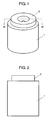
- Fig. 1 is a perspective view of a lens unit in one preferred embodiment of the present invention. Fig. 2 is a front view of the same. Fig. 3 is a sectional view along III - III line of Fig. 1. Fig. 4 is a front view of a portable telephone equipped with the lens unit of Fig. 3. Fig. 5 is a sectional view along V - V line of Fig. 4.
-
- One preferred embodiment of the present invention will be described in the following by using Fig. 1 to Fig. 3.
- A lens unit in the present preferred embodiment comprises
cylindrical holder 1, for example, made of resin such as polycarbonate,first lens 2,second lens 3, andthird lens 4 which are housed inholder 1.First lens 2 is for example made of transparent resin, and its top is formed oflens portion 2a, which is cylindrical having a top. Cylindricalsecond lens 3 made of glass is pressed intocylinder 2b of cylindricalfirst lens 2 having a top in such manner that the inner periphery ofcylinder 2b offirst lens 2 is pressed outwardly of the circumference by the outer periphery ofsecond lens 3. - Also, at the inner periphery of
holder 1 is disposed cylindrical holdingportion 1a spaced a predetermined distance from the inner periphery ofholder 1, and the outer periphery ofcylinder 2b offirst lens 2 is resiliently held by the inner periphery of holdingportion 1a. - That is, the cylinder of
first lens 2 is resiliently held by holdingportion 1a ofholder 1, and thereby, thefirst lens 2 andsecond lens 3 are held at a fixed position inholder 1. - Holding
portion 1a ofholder 1 is resiliently diametrically expandable, that is, formed from a resilient material, and its diameter is free to increase and decrease, and also, the inner peripheral diameter of holdingportion 1a is smaller than the outer peripheral diameter ofcylinder 2b offirst lens 2. Accordingly, in straight view of Fig. 3, pressing thecylinder 2b offirst lens 2 into holdingportion 1a ofholder 1 from above,first lens 2 can be resiliently held at a fixed position in holdingportion 1a ofholder 1. - Also, resin is used as the material for
holder 1 andfirst lens 2, and holdingportion 1a ofholder 1 is less in thickness thancylinder 2b offirst lens 2 as shown in Fig. 3. - That is, since holding
portion 1a ofholder 1 is less in thickness thancylinder 2b offirst lens 2, when the outer periphery ofcylinder 2b offirst lens 2 is pressed into the inner periphery ofholder 1 and is resiliently held, holdingportion 1a ofholder 1 is easily deformed. Accordingly, the deformation ofcylinder 2b offirst lens 2 andlens portion 2a connecting thereto can be lessened, and it is preferable as optical characteristic. -
Second lens 3 is an aspherical lens, and thesecond lens 3 is pressed intocylinder 2b offirst lens 2 bythrottle member 5. - That is,
cylindrical throttle member 5 made of resin such as polycarbonate is provided withpressing portion 5a which pressessecond lens 3 intocylinder 2b offirst lens 2 andpressing portion 5b which pressesfirst lens 2 already installed. - Accordingly, press-fitting the throttle member into one end of the inner periphery of
holder 1, it is possible to easily perform the positioning offirst lens 2 inholder 1 and the positioning ofsecond lens 3 incylinder 2b offirst lens 2. - As to pressing the
second lens 3 bythrottle member 5,second lens 3 is made of glass andfirst lens 2 is made of resin, and this is one of the characteristics of the present invention. - That is,
second lens 3 is made of glass, andfirst lens 2 is made of resin, and thereby, it is possible to makesecond lens 3 harder thanfirst lens 2. Whensecond lens 3 is pressed intocylinder 2b offirst lens 2, the inner periphery ofcylinder 2b offirst lens 2 is deformed, making the job easier, and also,second lens 3 pressed therein can be reliably held. - Also,
first lens 2 is made of resin, andsecond lens 3 is made of glass, making the lenses different in hardness and causingcylinder 2b offirst lens 2 to be deformed, and thereby, the inner periphery ofcylinder 2b offirst lens 2 comes in tight contact with the outer periphery ofsecond lens 3. - And, the inner periphery of
cylinder 2b offirst lens 2 is in tight contact with the outer periphery ofsecond lens 3, and the space betweenfirst lens 2 andsecond lens 3 is substantially sealed up, and it is possible to preventfirst lens 2 made of resin from being deteriorated due to moisture in the air that might be otherwise intruded into the space. - Also, the following configuration is effective for making the inner periphery of
cylinder 2b offirst lens 2 come in tight contact with the outer periphery ofsecond lens 3. That is, the inner periphery ofcylinder 2b offirst lens 2 is sloped so as to be decreased in diameter fromcollar 2c towardlens portion 2a. - In such a configuration, when
second lens 3 is pressed intocylinder 2b offirst lens 2 bythrottle member 5, thesecond lens 3 can be disposed at a fixed position because of abutting the slope. - The abutment of pressing
portion 5a ofthrottle member 5 ofsecond lens 3 is plane. And, in this way, since thesecond lens 3 portion on which pressingportion 5a ofthrottle member 5 abuts is plane, whensecond lens 3 is pressed intocylinder 2b offirst lens 2 bythrottle member 5, thesecond lens 3 is subjected to nearly uniform pressure over its entire periphery, and thereby, proper press-fitting can be realized. - Here, holding
portion 1a ofholder 1 is described in detail. - At one end of holding
portion 1a ofholder 1 isintegrated flange 1b inwardly extended from the inner periphery of holdingportion 1a ofholder 1.Lens portion 2a offirst lens 2 is inserted into holdingportion 1a from one end of holdingportion 1a ofholder 1, andcollar 2c outwardly extended toward the inner periphery ofholder 1 at a portion outside the holding portion ofcylinder 2b offirst lens 2 is abutted onflange 1b of holdingportion 1a ofholder 1. - In the above configuration, when
first lens 2 is inserted into holdingportion 1a ofholder 1,collar 2c offirst lens 2 is abutted onflange 1b of holdingportion 1a ofholder 1, and thereby,first lens 2 can be reliably held inholder 1. - At least one of the inner periphery of holding
portion 1a ofholder 1 and the outer periphery ofcylinder 2b offirst lens 2 being roughened, when the outer periphery ofcylinder 2b offirst lens 2 is pressed into the inner periphery of holdingportion 1a ofholder 1, the inner periphery and the outer periphery bite into each other, and thereby,first lens 2 is reliably held by holdingportion 1a. - In the above configuration, the especially important point is that the abutment of the inner periphery of
cylinder 2b offirst lens 2 and the outer periphery ofsecond lens 3 is closer to thecollar 2c side than the abutment offlange 1b andcollar 2c. - That is, when
second lens 3 is pressed intocylinder 2b offirst lens 2, the outer periphery ofsecond lens 3 comes in contact with the inner periphery ofcylinder 2b offirst lens 2. Accordingly, whenfirst lens 2 is deformed outwardly,only collar 2c is widened outwardly, and thereby, the lens is easily deformed, improving the workability. - Due to the above configuration, as shown in Fig. 3, the
optical axis 7first lens 2,second lens 3 andthird lens 4 can be aligned inholder 1. - And these lens units shown in Fig. 1 to Fig. 3 are mounted in
main body case 8 of a portable telephone shown as an example of electronic apparatus as shown in Fig. 4 and Fig. 5. - In Fig. 5, since
lens portion 2a offirst lens 2 is opposed to imagepickup element 10 inmain body case 8, proper image forming can be realized by a lens unit withfirst lens 2,second lens 3 andthird lens 4 integrated. - That is, in the present preferred embodiment, as shown in Fig. 4 and Fig. 5, the lens unit is housed in
main body case 8, and the surface ofthrottle member 5 of the lens unit is not protruded from the surface ofmain body case 8. - In addition, since
throttle member 5 of the lens unit is not protruded frommain body case 8, it is possible to prevent excessive forces from being applied to throttlemember 5 from outsidemain body case 8. Thus,first lens 2 can be prevented from being excessively pushed and damaged bythrottle member 5. - Further, as shown in Fig. 5, since the surface of
throttle member 5 of the lens unit is covered withtransparent cover 11, application of excessive forces to throttlemember 5 can be avoided outside themain body case 8, and therefore, it is possible to eliminate such trouble thatfirst lens 2 is excessively pushed and damaged bythrottle member 5. - In Fig. 5, same components and portions as those in Fig. 3 are given same reference numerals. Also the one shown in Fig. 5 comprises infrared
ray cutting filter 9, image pickup element (charge coupled element) 10,transparent cover 11, andlens unit fixture 12. - As described above, the lens unit of the present invention is configured in that the first lens and the second lens are integrated in a holder together with a cylindrical holder. Accordingly, due to the combination of the first and second lenses at least, the lens aberration is improved, and the image pickup effect is enhanced in various electronic apparatuses.
Claims (60)
- A lens unit comprising a cylindrical holder, a first lens and a second lens housed in the holder, wherein the first lens is cylindrical having a top that functions as a lens, and the second lens is pressed into the cylinder of the first lens having a top in such manner that the inner periphery of the cylindrical portion of the first lens is pressed outwardly of the circumference by the outer periphery of the second lens.
- The lens unit of claim 1, wherein the inner periphery of the holder is provided with a cylindrical holding portion disposed at a predetermined distance from the inner periphery of the holder, and the outer periphery of the first lens cylinder is resiliently held by the inner periphery of the holding portion.
- The lens unit of claim 2, wherein the holding portion of the holder is shaped so as to be resiliently increased in diameter, and also, the inner periphery of the holding portion is smaller in diameter than the outer periphery of the first lens cylinder.
- The lens unit of claim 3, wherein the holder and the first lens are made of resin, and also, the holding portion of the holder is less in thickness than the cylinder of the first lens.
- The lens unit of claim 4, wherein the second lens is made of glass, and the first lens is made of resin.
- The lens unit of claim 5, wherein at least one of the inner periphery of the holding portion of the holder and outer periphery of the first lens cylinder is roughened.
- The lens unit of claim 3, wherein the cylinder of the first lens is higher in hardness than the holding portion of the holder.
- The lens unit of claim 7, wherein at least one of the inner periphery of the holding portion of the holder and the outer periphery of the first lens cylinder is roughened.
- The lens unit of claim 8, wherein the second lens is made of glass, and the first lens is made of resin.
- The lens unit of claim 7, wherein the second lens is harder than the first lens.
- The lens unit of claim 3, wherein the inner periphery of the first lens cylinder is in tight contact with the outer periphery of the second lens.
- The lens unit of claim 11, wherein a flange inwardly extending from the inner periphery of the holding portion of the holder is integrated with one end of the holding portion of the holder, and the lens portion of the first lens is inserted into the holding portion from one end of the holding portion of the holder, and a collar outwardly extended toward the inner periphery of the holder at a portion outside the holding portion of the first lens cylinder is abutted on the flange of the holding portion of the holder.
- The lens unit of claim 12, wherein one end of the inner periphery of the holder is provided with a cylindrical throttle member which presses the collar of the first lens against the flange of the holding portion.
- The lens unit of claim 13, wherein the throttle member is provided with a pressing portion for pressing the second lens into the cylindrical portion of the first lens.
- The lens unit of claim 14, wherein the abutment of the inner periphery of the first lens cylinder and the outer periphery of the second lens is closer to the collar than the abutment of the flange and the collar.
- The lens unit of claim 15, wherein the inner periphery of the first lens cylinder is sloped so as to be decreased in diameter from the collar toward the lens portion.
- The lens unit of claim 14, wherein a portion coming in contact with the pressing portion of the throttle member of the second lens is plane.
- A lens unit comprising a cylindrical holder, a first lens and a second lens housed in the holder, wherein the first lens is cylindrical having a top made of resin that functions as a lens, and the second lens made of glass is pressed into the cylinder of the first lens having a top in such manner that the inner periphery of the first lens cylinder is pressed outwardly of the circumference by the outer periphery of the second lens.
- The lens unit of claim 18, wherein the inner periphery of the holder is provided with a cylindrical holding portion disposed at a predetermined distance from the inner periphery of the holder, and the outer periphery of the first lens cylinder is resiliently held by the inner periphery of the holding portion.
- The lens unit of claim 19, wherein the holding portion of the holder is shaped so as to be resiliently increased in diameter, and also, the inner periphery of the holding portion is smaller in diameter than the outer periphery of the first lens cylinder.
- The lens unit of claim 20, wherein the holder and the first lens are made of resin, and also, the holding portion of the holder is less in thickness than the cylindrical portion of the first lens.
- The lens unit of claim 21, wherein the second lens is made of glass, and the first lens is made of resin.
- The lens unit of claim 22, wherein at least one of the inner periphery of the holding portion of the holder and the outer periphery of the first lens cylinder is roughened.
- The lens unit of claim 20, wherein the cylindrical portion of the first lens is higher in hardness than the holding portion of the holder.
- The lens unit of claim 24, wherein at least one of the inner periphery of the holding portion of the holder and the outer periphery of the first lens cylinder is roughened.
- The lens unit of claim 25, wherein the second lens is made of glass, and the first lens is made of resin.
- The lens unit of claim 24, wherein the second lens is harder than the first lens.
- The lens unit of claim 20, wherein the inner periphery of the first lens cylinder is in tight contact with the outer periphery of the second lens.
- The lens unit of claim 28, wherein a flange inwardly extending from the inner periphery of the holding portion of the holder is integrated with one end of the holding portion of the holder, and the lens portion of the first lens is inserted into the holding portion from one end of the holding portion of the holder, and a collar outwardly extended toward the inner periphery of the holder at a portion outside the holding portion of the first lens cylinder is abutted on the flange of the holding portion of the holder.
- The lens unit of claim 29, wherein one end of the inner periphery of the holder is provided with a cylindrical throttle member which presses the collar of the first lens against the flange of the holding portion.
- The lens unit of claim 30, wherein the throttle member is provided with a pressing portion for pressing the second lens into the cylindrical portion of the first lens.
- The lens unit of claim 31, wherein the abutment of the inner periphery of the first lens cylinder and the outer periphery of the second lens is closer to the collar than the abutment of the flange and the collar.
- The lens unit of claim 32, wherein the inner periphery of the first lens cylinder is sloped so as to be decreased in diameter from the collar toward the lens portion.
- The lens unit of claim 31, wherein a portion coming in contact with the pressing portion of the throttle member of the second lens is plane.
- A lens unit comprising a cylindrical holder, a first lens and a second lens housed in the holder, wherein the first lens is cylindrical having a top made that functions as a lens, and the second lens is pressed into the cylindrical portion of the first lens having a top in such manner that the inner periphery of the first lens cylinder is pressed outwardly of the circumference along the outer periphery of the second lens.
- The lens unit of claim 35, wherein the inner periphery of the holder is provided with a cylindrical holding portion disposed at a predetermined distance from the inner periphery of the holder, and the outer periphery of the first lens cylinder is resiliently held by the inner periphery of the holding portion.
- The lens unit of claim 36, wherein the holding portion of the holder is shaped so as to be resiliently increased in diameter, and also, the inner periphery of the holding portion is smaller in diameter than the outer periphery of the first lens cylinder.
- The lens unit of claim 37, wherein the holder and the first lens are made of resin, and also, the holding portion of the holder is less in thickness than the cylindrical portion of the first lens.
- The lens unit of claim 38, wherein the second lens is made of glass, and the first lens is made of resin.
- The lens unit of claim 39, wherein at least one of the inner periphery of the holding portion of the holder and the outer periphery of the first lens cylinder is roughened.
- The lens unit of claim 37, wherein the cylindrical portion of the first lens is higher in hardness than the holding portion of the holder.
- The lens unit of claim 41, wherein at least one of the inner periphery of the holding portion of the holder and the outer periphery of the first lens cylinder is roughened.
- The lens unit of claim 42, wherein the second lens is made of glass, and the first lens is made of resin.
- The lens unit of claim 41, wherein the second lens is harder than the first lens.
- The lens unit of claim 37, wherein the inner periphery of the first lens cylinder is in tight contact with the outer periphery of the second lens.
- The lens unit of claim 45, wherein a flange inwardly extending from the inner periphery of the holding portion of the holder is integrated with one end of the holding portion of the holder, and the lens portion of the first lens is inserted into the holding portion from one end of the holding portion of the holder, and a collar outwardly extended toward the inner periphery of the holder at a portion outside the holding portion of the first lens cylinder is abutted on the flange of the holding portion of the holder.
- The lens unit of claim 46, wherein one end of the inner periphery of the holder is provided with a cylindrical throttle member which presses the collar of the first lens against the flange of the holding portion.
- The lens unit of claim 47, wherein the throttle member is provided with a pressing portion for pressing the second lens into the cylindrical portion of the first lens.
- The lens unit of claim 48, wherein the abutment of the inner periphery of the first lens cylinder and the outer periphery of the second lens is closer to the collar than the abutment of the flange and the collar.
- The lens unit of claim 49, wherein the inner periphery of the first lens cylinder is sloped so as to be decreased in diameter from the collar toward the lens portion.
- The lens unit of claim 48, wherein a portion coming in contact with the pressing portion of the throttle member of the second lens is plane.
- An electronic apparatus comprising a main body case, a lens unit disposed in the main body case, and an image pickup element disposed in the main body case opposing to the lens unit, wherein any one of the lens units of claims 1 to 17 is disposed in such manner that the lens portion side of the first lens is opposed to the image pickup element in the main body case.
- The electronic apparatus of claim 52, wherein the throttle member surface of the lens unit is covered with a transparent cover.
- The electronic apparatus of claim 52, wherein the lens unit is housed in the main body case, and the throttle member surface of the lens unit is not protruded from the main body case surface.
- An electronic apparatus comprising a main body case, a lens unit disposed in the main body case, and an image pickup element disposed in the main body case opposing to the lens unit, wherein any one of the lens units of claims 18 to 34 is disposed in such manner that the lens portion side of the first lens is opposed to the image pickup element in the main body case.
- The electronic apparatus of claim 55, wherein the throttle member surface of the lens unit is covered with a transparent cover.
- The electronic apparatus of claim 55, wherein the lens unit is housed in the main body case, and the throttle member surface of the lens unit is not protruded from the main body case surface.
- An electronic apparatus comprising a main body case, a lens unit disposed in the main body case, and an image pickup element disposed in the main body case opposing to the lens unit, wherein any one of the lens units of claims 35 to 51 is disposed in such manner that the lens portion side of the first lens is opposed to the image pickup element in the main body case.
- The electronic apparatus of claim 58, wherein the throttle member surface of the lens unit is covered with a transparent cover.
- The electronic apparatus of claim 58, wherein the lens unit is housed in the main body case, and the throttle member surface of the lens unit is not protruded from the main body case surface.
Applications Claiming Priority (2)
| Application Number | Priority Date | Filing Date | Title |
|---|---|---|---|
| JP2003426810 | 2003-12-24 | ||
| JP2003426810A JP4507588B2 (en) | 2003-12-24 | 2003-12-24 | Lens unit and electronic equipment using it |
Publications (1)
| Publication Number | Publication Date |
|---|---|
| EP1550893A1 true EP1550893A1 (en) | 2005-07-06 |
Family
ID=34567552
Family Applications (1)
| Application Number | Title | Priority Date | Filing Date |
|---|---|---|---|
| EP04030426A Withdrawn EP1550893A1 (en) | 2003-12-24 | 2004-12-22 | Lens unit and electronic apparatus using the same |
Country Status (4)
| Country | Link |
|---|---|
| US (1) | US7542221B2 (en) |
| EP (1) | EP1550893A1 (en) |
| JP (1) | JP4507588B2 (en) |
| CN (1) | CN1295535C (en) |
Families Citing this family (9)
| Publication number | Priority date | Publication date | Assignee | Title |
|---|---|---|---|---|
| US7372647B2 (en) * | 2004-12-29 | 2008-05-13 | Finisar Corporation | Lens mount assembly for optical components |
| JP4189769B2 (en) * | 2006-10-18 | 2008-12-03 | 進展産業株式会社 | Imaging device |
| JP5187342B2 (en) * | 2010-04-23 | 2013-04-24 | ウシオ電機株式会社 | LED light emitting device |
| USD743382S1 (en) * | 2013-09-20 | 2015-11-17 | Panasonic Intellectual Property Management Co., Ltd. | Microphone |
| CN109151270B (en) * | 2018-08-22 | 2020-10-09 | 维沃移动通信有限公司 | A lens module installation structure and mobile terminal |
| CN110082870B (en) * | 2019-05-31 | 2024-06-25 | 浙江舜宇光学有限公司 | TO-CAN pipe cap |
| JP7514634B2 (en) * | 2020-03-05 | 2024-07-11 | 株式会社タムロン | Lens unit |
| JP2022140135A (en) * | 2021-03-12 | 2022-09-26 | 株式会社リコー | Lens unit, stereo camera, and movable body |
| JP2022179073A (en) * | 2021-05-21 | 2022-12-02 | 株式会社エンプラス | Optical receptacle and optical module |
Citations (4)
| Publication number | Priority date | Publication date | Assignee | Title |
|---|---|---|---|---|
| JP2002286987A (en) * | 2001-03-23 | 2002-10-03 | Kanto Tatsumi Denshi Kk | Method for positioning and fixing two or more lenses in lens barrel and optical equipment applying the same |
| US20020167605A1 (en) * | 2001-05-09 | 2002-11-14 | Kazuo Akimoto | Photographing apparatus |
| JP2002350608A (en) * | 2001-05-23 | 2002-12-04 | Konica Corp | Imaging lens, imaging apparatus, mold, and method of molding imaging lens |
| US6559439B1 (en) * | 1999-12-15 | 2003-05-06 | Olympus Optical Co., Ltd. | Image taking lens unit with frame member for positioning lens and substrate |
Family Cites Families (11)
| Publication number | Priority date | Publication date | Assignee | Title |
|---|---|---|---|---|
| JPS56121005A (en) * | 1980-02-27 | 1981-09-22 | Canon Inc | Extension tube |
| JPH03237409A (en) * | 1990-02-15 | 1991-10-23 | Ogura Houseki Seiki Kogyo Kk | Press-fitting and holding mechanism for member molded of brittle material |
| JPH0650013U (en) * | 1992-12-15 | 1994-07-08 | 旭光学工業株式会社 | Lens support structure |
| JPH071602A (en) * | 1993-06-17 | 1995-01-06 | Sony Corp | Lens joining device |
| JPH0836124A (en) * | 1994-07-25 | 1996-02-06 | Nikon Corp | Lens holding device and lens system including the device |
| JPH08297237A (en) * | 1995-04-27 | 1996-11-12 | Nikon Corp | Lens barrel |
| US6594204B1 (en) * | 1999-03-31 | 2003-07-15 | Sony Corporation | Lens holder, method for manufacturing lens holder, metal die for producing lens holder and objective lens device |
| JP2000347088A (en) * | 1999-03-31 | 2000-12-15 | Sony Corp | Lens holder, method for manufacturing lens holder, mold for manufacturing lens holder, and objective lens device |
| JP2003262778A (en) * | 2002-03-07 | 2003-09-19 | Konica Corp | Photographing equipment |
| JP2003295028A (en) * | 2002-04-01 | 2003-10-15 | Sumitomo Heavy Ind Ltd | Method of manufacturing holder-integrated lens, holder- integrated lens, method of manufacturing intermediate parts for holder-integrated lens and intermediate parts for holder-integrated lens |
| JP4269334B2 (en) * | 2002-10-28 | 2009-05-27 | コニカミノルタホールディングス株式会社 | Imaging lens, imaging unit, and portable terminal |
-
2003
- 2003-12-24 JP JP2003426810A patent/JP4507588B2/en not_active Expired - Fee Related
-
2004
- 2004-12-22 EP EP04030426A patent/EP1550893A1/en not_active Withdrawn
- 2004-12-22 US US11/017,882 patent/US7542221B2/en not_active Expired - Fee Related
- 2004-12-24 CN CNB2004101048837A patent/CN1295535C/en not_active Expired - Fee Related
Patent Citations (4)
| Publication number | Priority date | Publication date | Assignee | Title |
|---|---|---|---|---|
| US6559439B1 (en) * | 1999-12-15 | 2003-05-06 | Olympus Optical Co., Ltd. | Image taking lens unit with frame member for positioning lens and substrate |
| JP2002286987A (en) * | 2001-03-23 | 2002-10-03 | Kanto Tatsumi Denshi Kk | Method for positioning and fixing two or more lenses in lens barrel and optical equipment applying the same |
| US20020167605A1 (en) * | 2001-05-09 | 2002-11-14 | Kazuo Akimoto | Photographing apparatus |
| JP2002350608A (en) * | 2001-05-23 | 2002-12-04 | Konica Corp | Imaging lens, imaging apparatus, mold, and method of molding imaging lens |
Non-Patent Citations (2)
| Title |
|---|
| PATENT ABSTRACTS OF JAPAN vol. 2003, no. 02 5 February 2003 (2003-02-05) * |
| PATENT ABSTRACTS OF JAPAN vol. 2003, no. 04 2 April 2003 (2003-04-02) * |
Also Published As
| Publication number | Publication date |
|---|---|
| CN1295535C (en) | 2007-01-17 |
| JP4507588B2 (en) | 2010-07-21 |
| CN1637453A (en) | 2005-07-13 |
| JP2005189261A (en) | 2005-07-14 |
| US7542221B2 (en) | 2009-06-02 |
| US20050200979A1 (en) | 2005-09-15 |
Similar Documents
| Publication | Publication Date | Title |
|---|---|---|
| US20240329355A1 (en) | Lens unit | |
| CN100468192C (en) | Fixing structure of camera module, its fixing method and mobile terminal using same | |
| US20240329354A1 (en) | Lens unit | |
| US20240329356A1 (en) | Lens unit and lens alignment method | |
| US7626773B2 (en) | Lens unit | |
| US20240329353A1 (en) | Lens unit | |
| US20120162795A1 (en) | Lens barrel, imaging device and mobile terminal device | |
| US7660057B2 (en) | Lens assembly and imaging apparatus | |
| KR100468908B1 (en) | Attachment structure for joint boot | |
| JP2024147054A (en) | Lens unit | |
| US7542221B2 (en) | Lens unit and electronic apparatus using same | |
| US7894714B2 (en) | Lens assembly and imaging apparatus | |
| US8672712B2 (en) | Shield and circuit board module having the same | |
| JP2019179075A (en) | Lens unit | |
| JP5467205B2 (en) | Optical lens | |
| JP6332964B2 (en) | Lens unit and imaging device | |
| US20200049952A1 (en) | Lens module | |
| JP7103819B2 (en) | Lens unit | |
| US10989892B2 (en) | Lens module | |
| JP2008046169A (en) | Lens unit | |
| JP2005189261A5 (en) | ||
| US20240402470A1 (en) | Cemented lens, imaging lens, and imaging device | |
| CN110858021B (en) | Lens unit | |
| JP2019086671A (en) | Lens barrel, lens unit, and camera module | |
| JP2704349B2 (en) | Lens holding device |
Legal Events
| Date | Code | Title | Description |
|---|---|---|---|
| PUAI | Public reference made under article 153(3) epc to a published international application that has entered the european phase |
Free format text: ORIGINAL CODE: 0009012 |
|
| AK | Designated contracting states |
Kind code of ref document: A1 Designated state(s): AT BE BG CH CY CZ DE DK EE ES FI FR GB GR HU IE IS IT LI LT LU MC NL PL PT RO SE SI SK TR |
|
| AX | Request for extension of the european patent |
Extension state: AL BA HR LV MK YU |
|
| 17P | Request for examination filed |
Effective date: 20050615 |
|
| AKX | Designation fees paid |
Designated state(s): DE FR GB |
|
| RAP1 | Party data changed (applicant data changed or rights of an application transferred) |
Owner name: PANASONIC CORPORATION |
|
| 17Q | First examination report despatched |
Effective date: 20110817 |
|
| STAA | Information on the status of an ep patent application or granted ep patent |
Free format text: STATUS: THE APPLICATION IS DEEMED TO BE WITHDRAWN |
|
| 18D | Application deemed to be withdrawn |
Effective date: 20140927 |