EP1804036A2 - Ultraschall-clamp-on-durchflussmesser - Google Patents
Ultraschall-clamp-on-durchflussmesser Download PDFInfo
- Publication number
- EP1804036A2 EP1804036A2 EP06125730A EP06125730A EP1804036A2 EP 1804036 A2 EP1804036 A2 EP 1804036A2 EP 06125730 A EP06125730 A EP 06125730A EP 06125730 A EP06125730 A EP 06125730A EP 1804036 A2 EP1804036 A2 EP 1804036A2
- Authority
- EP
- European Patent Office
- Prior art keywords
- subcomponent
- sound
- angle
- pipeline
- ultrasonic
- Prior art date
- Legal status (The legal status is an assumption and is not a legal conclusion. Google has not performed a legal analysis and makes no representation as to the accuracy of the status listed.)
- Granted
Links
Images


Classifications
-
- G—PHYSICS
- G01—MEASURING; TESTING
- G01F—MEASURING VOLUME, VOLUME FLOW, MASS FLOW OR LIQUID LEVEL; METERING BY VOLUME
- G01F1/00—Measuring the volume flow or mass flow of fluid or fluent solid material wherein the fluid passes through a meter in a continuous flow
- G01F1/66—Measuring the volume flow or mass flow of fluid or fluent solid material wherein the fluid passes through a meter in a continuous flow by measuring frequency, phase shift or propagation time of electromagnetic or other waves, e.g. using ultrasonic flowmeters
- G01F1/662—Constructional details
-
- G—PHYSICS
- G01—MEASURING; TESTING
- G01F—MEASURING VOLUME, VOLUME FLOW, MASS FLOW OR LIQUID LEVEL; METERING BY VOLUME
- G01F1/00—Measuring the volume flow or mass flow of fluid or fluent solid material wherein the fluid passes through a meter in a continuous flow
- G01F1/66—Measuring the volume flow or mass flow of fluid or fluent solid material wherein the fluid passes through a meter in a continuous flow by measuring frequency, phase shift or propagation time of electromagnetic or other waves, e.g. using ultrasonic flowmeters
- G01F1/663—Measuring the volume flow or mass flow of fluid or fluent solid material wherein the fluid passes through a meter in a continuous flow by measuring frequency, phase shift or propagation time of electromagnetic or other waves, e.g. using ultrasonic flowmeters by measuring Doppler frequency shift
Definitions
- the invention relates to a clamp-on ultrasonic flowmeter for determining and / or monitoring the volume or mass flow of a medium, which flows through a pipeline in the direction of the longitudinal axis of the pipeline.
- Ultrasonic flowmeters of the aforementioned type are widely used in process and automation technology. They allow the volumetric and / or mass flow of a medium in a pipeline to be determined without contact.
- Clamp-on flowmeters are for example in the EP 0 686 255 B1 , of the U.S. Patent 4,484,478 or the U.S. Patent 4,598,593 described.
- the applicant Clamp-on flow meters which operate on the transit time difference method, offered and sold under the name PROSONIC FLOW.
- the different transit time of ultrasonic measurement signals in the flow direction and against the flow direction of the medium is evaluated. From the transit time difference of the ultrasonic measuring signals, the flow rate and thus, with a known diameter of the pipeline, the volumetric flow or, in the case of a known or measured density of the medium, the mass flow rate can be determined.
- ultrasonic measurement signals are coupled into the flowing medium at a predetermined frequency.
- the reflected in the medium ultrasonic measurement signals are evaluated.
- the flow velocity of the medium or the volume and / or mass flow can also be determined.
- the ultrasonic measuring signals are at a predetermined angle in the pipe or in the measuring tube, in which or in which the flowing medium is, coupled and uncoupled.
- the ultrasonic measuring signals are coupled into the pipeline via a feed body or a coupling wedge or coupled out of the pipeline or out of the measuring tube.
- the main component of an ultrasound sensor is at least one piezoelectric element which generates and / or receives the ultrasound measurement signals in a defined frequency range.
- the ultrasonic measurement signals generated in a piezoelectric element are conducted via a coupling wedge or a flow body and the pipe wall in the fluid medium.
- the medium is - as already mentioned - either a liquid or a gas. Due to the speed of sound, which is relatively dependent on the medium, the ultrasound measurement signals are refracted at the interface of two different media.
- the respective refraction angle is calculated according to Snell's law, that is, the angle of refraction depends on the ratio of the propagation velocities of two adjacent media.
- Snell's law A corresponding solution known from the prior art is shown in FIG.
- the coupling and decoupling of the ultrasonic measuring signals is particularly problematic if the pipeline is made of metal and a gaseous medium flows in the pipeline. Since the speed of sound of a metal and a gas are usually an order of magnitude apart, at the interface both at the coupling and the decoupling a large part of the Ultrasound measurement signals reflected back. The reflected portion is so large that reliable flow measurement is not possible with a conventional ultrasonic sensor. If, in addition, error sources occur which are connected, for example, with installation and assembly or with changes in the ambient conditions, a conventional ultrasonic flowmeter is unsuitable for the respective application.
- the invention has for its object to provide a device in which installation associated with the installation and measurement errors are effectively avoided.
- the object is achieved in that at least one ultrasonic sensor is provided, which has at least one sound-generating element and a flow body and the ultrasonic measuring signals irradiated under a Einstrahl- / failure angle in the pipeline or receives from the pipe, that a first adjustment mechanism is provided , which is designed such that the Einstrahl- / beam angle of the ultrasonic sensor is adjustable within predetermined limits, and that a control / evaluation unit is provided, the volume or mass flow of the medium in the pipeline by the transit time difference method, the cross-correlation method or Doppler method determined.
- a direction coding unit is provided on the adjusting mechanism.
- Vorlaufharmacin are well known and serve as a coupling element between the sound-generating element and the pipeline.
- the lead body is usually geometrically formed so that a defined angle q VK occurs between the normal of the thickness oscillation plane of the piezoelectric element and the tube radius.
- ⁇ M the largest possible angle for the pipe radius during the propagation time difference measurement.
- the angle is 90 °, ie the sound signals are in this case parallel to the longitudinal axis of the pipeline.
- Snell's law of pure longitudinal waves total reflection of the sound waves already occurs above a relatively small angle. This is the case, for example, when the sound signals from a liquid in a steel pipe to pass.
- the total reflection angle is at the transition from water to steel at q total, H2O »14 ° for longitudinal waves.
- the energy-efficient angle range for transverse waves in steel pipes can be described by the following estimate: 38 ° £ q Slahl £ 70 °.
- lead bodies are usually designed to excite a transverse wave at a constant angle q of steel , which is within the aforementioned angular range. Further information can be found in the publication: 'Ultrasonic Sensors' by Asher, RC, IOP Publishing Ltd 1997.
- an ultrasonic clamp-on flowmeter in which the transmitting and / or receiving ultrasonic sensors have a defined and constant distance from one another by suitable design measures.
- the advantage of the solution according to the invention with angle-adjustable flow body is the fact that the correct installation of the measuring device on the pipeline is considerably simplified. In particular, assembly-related inaccuracies and user errors are avoided.
- an angle-adjustable clamp-on flowmeter according to the invention in connection with the generation of so-called lamb waves is recommended.
- the pipeline is excited by means of sound-generating elements, in particular thus by means of piezoelectric elements, over its entire thickness to shear oscillations.
- longitudinal sound waves are generated, which pass through the medium under an angle prescribed by the law of Snellius parallel to each other and all arrive at the same time at the ultrasonic sensor serving as a receiver.
- ⁇ 0 is the angle between the thickness plane of the piezo-electric element and the radius of the pipeline, must be present in principle for each pipe material either a suitably tuned lead body material or the appropriately tuned Einstrahl- / failure angle.
- the angle ⁇ 0 can be adapted quickly and easily to the respective conditions.
- entire classes of materials can be covered with a single clamp-on ultrasonic sensor for Lamb waves. The prerequisite for this, of course, is that the angle adjustability is present at the transmitting and at the receiving ultrasonic sensor.
- the ultrasonic flowmeter according to the invention which operates on the basis of lamb waves, in the gas flow measurement.
- Lamb waves of the 0th mode must be excited in the usual metal pipelines with relatively low frequencies.
- ultrasonic waves with a low frequency are particularly well suited for measurements in gaseous or vaporous media.
- the adjusting mechanism is designed so that the Einstrahl- / angle of the ultrasonic sensor is automatically and / or manually adjustable.
- the adjustment mechanism is designed essentially such that it converts a linear movement into a defined rotational movement of the sound-generating element.
- the flow body consists of a first subcomponent and a second subcomponent.
- the first subcomponent is, for example, a rotationally symmetric element to which the sound generating element is connected;
- the first subcomponent is rotatably mounted in a corresponding recess in the second subcomponent of the flow body.
- the first subcomponent is rotatably mounted in the second subcomponent via a lever against the restoring force of a spring.
- the first subcomponent is rotatably mounted in the second subcomponent via a gear with a translation drive.
- the second subcomponent preferably has a curved surface on which the first subcomponent with which the sound generating element is connected is positively guided.
- a linear drive is provided which is connected via a hinge connection with the first subcomponent.
- an advantageous embodiment of the device according to the invention proposes that the curved surface of the second subcomponent is curved concavely or convexly and that the surface of the first subcomponent that adjoins the corresponding curved surface of the second subcomponent is configured such that the first subcomponent and the second subcomponent each in the Lie flush against each other area of their contact surface.
- the curved surface of the second sub-component in longitudinal section has the shape of a semicircle.
- the curved surface of the first subcomponent and the curved surface of the second subcomponent are designed such that the center of the two curved surfaces at least approximately represents the coupling point of the sound signals in the pipeline.
- the volume or mass flow can be determined in different ways by means of ultrasonic measurement signals.
- two ultrasonic sensors are preferably arranged on a connecting line that is parallel to the longitudinal axis of the pipeline.
- the distance between the two ultrasonic sensors is rigid - but alternatively it can also be designed variable.
- a second adjustment mechanism is provided with which the two ultrasonic sensors along the connecting line can be moved relative to each other.
- control / evaluation unit successively controls the first adjustment mechanism for setting the beam / exit angle until a maximum signal strength has been determined for the transmitted or received ultrasonic measurement signal.
- a storage unit in which, depending on parameters which influence the Einstrahl- / beam angle of the ultrasonic measurement signals in the pipeline or from the pipeline, corresponding setpoints for the optimal Einstrahl- / failure angle are stored.
- the control / evaluation unit preferably determines the correspondingly stored optimum irradiation / failure angle based on the current values of the parameters and controls the first adjustment mechanism in such a way that the ultrasonic measurement signals enter or exit the pipeline below the optimum angle of incidence / exit into the pipeline be broadcast.
- the first adjusting mechanism is designed substantially such that it converts a bending of the actuating element into a defined rotational movement of the sound-generating element.
- first subcomponent and the second subcomponent of the flow body are made of the same material. Furthermore, it is advantageous if between the first sub-component and the second sub-component of the flow body, a coupling layer is provided which is configured so that they Transition of the sound signal between the two sub-components improved.
- the coupling layer may have a liquid, gelatinous or solid consistency.
- a piezoelectric drive is associated with the first adjustment mechanism.
- the two subcomponents of the flow body consist e.g. made of materials that have different velocities of sound and that break the sound signals differently depending on their position relative to the propagation direction of the sound.
- the sound-generating element is rigidly mounted on the housing so that it is decoupled from an adjusting movement of the adjustment '.
- FIG. 2 shows a longitudinal section through a first embodiment of an angle-adjustable ultrasonic sensor according to the invention
- FIG. 3 shows a longitudinal section through a second embodiment of an angle-adjustable ultrasonic sensor according to the invention
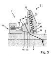
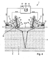
- FIG. 4 shows a longitudinal section through a clamp-on flowmeter according to the invention, in which the ultrasonic sensors shown in FIG. 3 are used,
- FIG. 5 shows a schematic representation of a third embodiment of an angle-adjustable ultrasonic sensor according to the invention
- FIG. 6 shows a schematic representation of a fourth embodiment of an angle-adjustable ultrasonic sensor according to the invention in a first position
- FIG. 7 shows a schematic representation of a fifth embodiment of an angle-adjustable ultrasonic sensor according to the invention in a first embodiment Position
- FIG. 7 a the ultrasonic sensor shown in FIG. 7 in a second position.
- the Einstrahl- or angle ⁇ between the thickness vibration level of the sound-generating piezoelectric element 5 and the radius of the pipe 3 by a manual operation of an adjusting mechanism '7 is adjusted.
- the adjusting mechanism 7 integral part of the flow body 6 and consists of a second sub-component 11 with a bore in which the first rotationally symmetrical component part 10 is rotatably mounted.
- the piezoelectric element 5 is rigidly fixed.
- the piezoelectric / piezoceramic element 5 is located between two circular cylinder halves 10a, 10b, which together add up to a solid cylinder forming the first subcomponent 10.
- the cylindrical component part 10 is rotatably inserted into a bore.
- a good acoustic contact is made by using a coupling paste / coupling layer 22 in the gap between the first subcomponent 10 and the bore in the second subcomponent.
- the coupling layer 22 also serves the fit lubrication.
- the adjusting mechanism 7 converts a linear movement, which is realized by the handwheel 24, the linear drive 15 and the lever 12, into an angular rotation of the first subcomponent 10 or of the piezoelectric element 5 fastened to the second subcomponent 10.
- the angular rotation of the first subcomponent 10 or this piezoelectric element takes place against the restoring force of the spring 13.
- the adjustment of the ultrasonic sensors 2 takes place directly after their mounting on the pipeline 3.
- an adjustment operating mode in which, for example, the signal strength and additionally the signal strength change in the form of display symbols, LEDs or a pointer are displayed.
- the operator knows the operator easily, as he has the optimal Einstrahl- / failure angle of the ultrasonic sensor 2, in which the signal strength of the desired signal is maximum, set.
- the manual angle adjustment described above can be implemented in a relatively simple manner in an automatic angle adjustment, for example, by the handwheel 24 by an electric motor, which is controlled by the control / evaluation unit 9, is replaced.
- the adjustment of the Einstrahl- / failure angle between the thickness vibration plane of the piezoelectric element 5 and the radius of the pipeline by a control loop, which is controlled by a microprocessor 25.
- the adjusting mechanism 7 operates under actuator control.
- it makes sense that the adjustment of the piezoelectric element 5 and / or the lead body 6 takes place not only after the assembly of the ultrasonic sensors 2 on the pipe 3, but cyclically at predetermined time intervals. This makes it possible to effectively and promptly compensate for changes in the operating conditions that directly affect the Einstrahl- / angle of the ultrasonic waves. Parameters that have a direct influence on the quality of the measurement are, in particular, large flow velocity or temperature changes.
- One possible flow diagram of the control algorithm is such that the adjusting mechanism adjusts the angle of the thickness vibration plane of the piezoelectric element 5 relative to the radius of the pipeline 3 by small angular amounts ⁇ ⁇ i in the positive and negative directions of rotation at regular intervals; the corresponding changes in the signal strength of the ultrasonic measurement signals are recorded. Based on the recorded data, the angular position ⁇ opt is then determined, at which a maximum signal strength is present. The corresponding, possibly changed angular position of the piezoelectric element 5 is subsequently determined by the Control / evaluation unit 9 controlled by the adjusting mechanism 7.
- the angle adjustment takes place on the flow body 6, with which the piezoelectric element 5 is rigidly connected.
- the underside - or the first curved surface 17 - of the first subcomponent 10 of the leading body 6 in longitudinal section has the shape of a circular cylinder surface.
- the first subcomponent 10 adjoins the curved surface 18 of the second subcomponent 11.
- the second subcomponent 11 is fastened to the pipeline 3.
- the first subcomponent 10 and the second subcomponent 11 are connected to one another via a tension spring 13.
- a tension spring 13 To improve the acoustic and mechanical properties is located between the two surfaces 17, 18, a coupling paste 22.
- the attached to the pipe 3 second component 11 is extended to one side, there to receive an adjustment mechanism 7 with a Stellaktor.
- a stepper motor Shown is a stepper motor, which can move a ball-bearing pull / push rod back and forth.
- an intermediate joint 16 which is fixedly connected to the flow body 6, the desired angular displacement is realized.
- both ultrasonic sensors 2 have an angle adjustment mechanism 7.
- either both ultrasonic sensors 2 have a fixed distance from each other, or the distance is designed to be variable via a second adjusting mechanism 8.
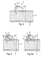
- FIGS. 6 and 6a show further embodiments of the angle-adjustable ultrasonic sensor 2 according to the invention.
- the flow body 6 is constructed of two parts: the second subcomponent 11, which is fixedly connected to the pipe 3, and the first subcomponent 10.
- the second subcomponent 11 has the shape of a semicircle.
- the voltage applied to the second sub-component 11 first curved surface 17 of The first subcomponent 10 is correspondingly concave shaped so that the first curved surface 17 of the first subcomponent 10 and the second curved surface 18 of the second subcomponent 11 are flush with each other.
- a coupling layer 22 is provided in the region of the contact surface 19.
- the first subcomponent 10, which carries the piezoelectric element 5, is rotatably mounted with respect to the second subcomponent 11.
- the rotation is indicated by the two curved arrows.
- the rotation can again be done manually or automatically.
- the advantage of the embodiment shown in FIG. 5 is that the exit point of the ultrasound measurement signals is constant during an adjustment of the incident / outgoing angle.
- the angular rotation takes place by means of a bending element 21, which is preferably a piezoelectric element or a bi-metal with heating wire.
- FIGS. 7 and 7a A further preferred embodiment of the angle-adjustable ultrasonic sensor 2 according to the invention is schematically illustrated in FIGS. 7 and 7a.
- both the first subcomponent 10 and the second subcomponent 11 each consist of two parts with different speeds of sound.
- the angular adjustment takes place via the refraction of the sound beam at the interface between the first subcomponent 10 and the first part of the second subcomponent 11a.
- the drive and the adjustment is again manually, or it is automatically controlled by a microprocessor.
- the parts 10, 10a; 11, 11a of the two subcomponents 10, 11 are each made of the same material, so that there is no refraction or change in the sound beam during the transition.
- flexure e.g. a piezo or a bi-metal with heating wire
Landscapes
- Physics & Mathematics (AREA)
- Electromagnetism (AREA)
- Fluid Mechanics (AREA)
- General Physics & Mathematics (AREA)
- Measuring Volume Flow (AREA)
- Investigating Or Analyzing Materials By The Use Of Ultrasonic Waves (AREA)
- Load-Engaging Elements For Cranes (AREA)
- Forklifts And Lifting Vehicles (AREA)
Abstract
Description
- Die Erfindung betrifft ein Clamp-On Ultraschall-Durchflussmessgerät zur Bestimmung und/oder Überwachung des Volumen- oder des Massedurchflusses eines Mediums, das eine Rohrleitung in Richtung der Längsachse der Rohrleitung durchströmt.
- Ultraschall-Durchflussmessgeräte der zuvor genannten Art werden vielfach in der Prozess- und Automatisierungstechnik eingesetzt. Sie erlauben es, den Volumen- und/oder Massedurchfluss eines Mediums in einer Rohrleitung berührungslos zu bestimmen. Clamp-On Durchflussmessgeräte sind beispielsweise in der
EP 0 686 255 B1 , derUS-PS 4,484,478 oder derUS-PS 4,598,593 beschrieben. Weiterhin werden von der Anmelderin Clamp-On Durchflussmessgeräte, die nach dem Laufzeitdifferenzverfahren arbeiten, unter der Bezeichnung PROSONIC FLOW angeboten und vertrieben. - Beim Laufzeitdifferenzverfahren wird die unterschiedliche Laufzeit von Ultraschall-Messsignalen in Strömungsrichtung und entgegen der Strömungsrichtung des Mediums ausgewertet. Aus der Laufzeitdifferenz der Ultraschall-Messsignale lässt sich die Fließgeschwindigkeit und damit bei bekanntem Durchmesser der Rohrleitung der Volumendurchfluss bzw. bei bekannter oder gemessener Dichte des Mediums der Massedurchfluss bestimmen.
- Beim Doppler-Prinzip werden Ultraschall-Messsignale mit einer vorgegebenen Frequenz in das strömende Medium eingekoppelt. Die in dem Medium reflektierten Ultraschall-Messsignale werden ausgewertet. Anhand einer zwischen dem eingekoppelten und dem reflektierten Ultraschall-Messsignal auftretenden Frequenzverschiebung lässt sich ebenfalls die Strömungsgeschwindigkeit des Mediums bzw. der Volumen und/oder Massedurchfluss bestimmen.
- Der Einsatz von Durchflussmessgeräten, die nach dem Doppler-Prinzip arbeiten, ist nur möglich, wenn in einem flüssigen Medium Luftbläschen oder Verunreinigungen vorhanden sind, an denen die Ultraschall-Messsignale reflektiert werden. Damit ist der Einsatz derartiger Ultraschall-Durchflussmessgeräte im Vergleich zu den Ultraschall-Durchflussmessgeräten, die z. B. nach dem Laufzeitdifferenz-Prinzip arbeiten, relativ stark beschränkt.
- Bei Ultraschall-Durchflussmessgeräten, wenn sie nach dem Laufzeitdifferenz-, dem Doppler- oder dem Kreuzkorrelationsverfahren arbeiten, werden die Ultraschall-Messsignale unter einem vorgegebenen Winkel in die Rohrleitung bzw. in das Messrohr, in der bzw. in dem sich das strömende Medium befindet, ein- und ausgekoppelt. Um eine optimale Impedanzanpassung und damit optimale Ein- und Auskopplung zu erreichen, werden die Ultraschall-Messsignale über einen Vorlaufkörper bzw. einen Koppelkeil in die Rohrleitung eingekoppelt bzw. aus der Rohrleitung bzw. aus dem Messrohr ausgekoppelt. Hauptbestandteil eines Ultraschallsensors ist zumindest ein piezoelektrisches Element, welches die Ultraschall-Messsignale in einem definierten Frequenzbereich erzeugt und/oder empfängt.
- Die in einem piezoelektrischen Element erzeugten Ultraschall-Messsignale werden über einen Koppelkeil bzw. einen Vorlaufkörper und die Rohrwand in das fluide Medium geleitet. Bei dem Medium handelt es sich - wie bereits gesagt - entweder um eine Flüssigkeit oder um ein Gas. Aufgrund der relativ stark von dem Medium abhängigen Schallgeschwindigkeit kommt es an der Grenzfläche zweier unterschiedlicher Medien zu einer Brechung der UltraschallMesssignale. Der jeweilige Brechungswinkel errechnet sich nach dem Snellius Gesetz, d.h der Brechungswinkel ist abhängig von dem Verhältnis der Ausbreitungsgeschwindigkeiten zweier aneinander grenzender Medien. Eine entsprechende aus dem Stand der Technik bekannte Lösung ist in der Fig. 1 dargstellt.
- Besonders problematisch gestaltet sich die Ein- und Auskopplung der Ultraschall-Messsignale, wenn die Rohrleitung aus Metall gefertigt ist und in der Rohrleitung ein gasförmiges Medium strömt. Da die Schallgeschwindigkeit eines Metalls und eines Gases üblicherweise um eine Größenordnung auseinander liegen, wird an der Grenzfläche sowohl beim Einkoppeln als auch beim Auskoppeln ein Großteil der Ultraschall-Messsignale rückreflektiert. Der rückreflektierte Anteil ist so groß, dass mit einem konventionellen Ultraschallsensor keine verlässliche Durchflussmessung möglich ist. Treten dann noch zusätzlich Fehlerquellen auf, die beispielsweise mit der Installation und Montage oder mit Änderungen der Umgebungsbedingungen zusammenhängen, so ist ein herkömmliches Ultraschall-Durchflussmessgerät für die jeweilige Applikation ungeeignet.
- Der Erfindung liegt die Aufgabe zugrunde, eine Vorrichtung vorzuschlagen, bei der mit der Montage verbundene Installations- und Messfehler effektiv vermieden werden.
- Die Aufgabe wird dadurch gelöst, dass zumindest ein Ultraschallsensor vorgesehen ist, der zumindest ein schallerzeugendes Element und einen Vorlaufkörper aufweist und der Ultraschall-Messsignale unter einem Einstrahl-/Ausfallwinkel in die Rohrleitung einstrahlt bzw. aus der Rohrleitung empfängt, dass ein erster Verstellmechanismus vorgesehen ist, der so ausgestaltet ist, dass der Einstrahl-/Ausstrahlwinkel des Ultraschallsensors in vorgegebenen Grenzen einstellbar ist, und dass eine Regel-/Auswerteeinheit vorgesehen ist, die den Volumen- oder den Massendurchfluss des Mediums in der Rohrleitung nach dem Laufzeitdifferenzverfahren, dem Kreuzkorrelationsverfahren oder dem Dopplerverfahren ermittelt. Bevorzugt ist übrigens an dem Verstellmechanismus eine Richtungscodiereinheit vorgesehen.
- Vorlaufkörper sind allgemein bekannt und dienen als Koppelglied zwischen dem schallerzeugenden Element und der Rohrleitung. Der Vorlaufkörper ist üblicherweise geometrisch so ausgebildet, dass zwischen der Normalen der Dickenschwingungsebene des piezoelektrischen Elements und dem Rohrradius ein definierter Winkel qVK auftritt. Zur Maximierung des Messeffekts muss bei der Laufzeitdifferenzmessung der Schallpfad durch das in der Rohrleitung strömende Medium einen möglichst großen Winkel Θ M (siehe Fig. 1) zum Rohrradius aufweisen. Idealerweise liegt der Winkel bei 90°, d.h. die Schallsignale verlaufen in diesem Fall parallel zur Längsachse der Rohrleitung. Weiterhin ist bekannt, dass entsprechend dem Brechungsgesetz nach Snellius bei reinen Longitudinalwellen bereits oberhalb eines relativ kleinen Winkels eine Totalreflexion der Schallwellen auftritt. Dies ist der Fall, wenn beispielsweise die Schallsignale von einer Flüssigkeit in eine Rohrleitung aus Stahl übergehen sollen. Der Totalreflexionswinkel liegt beim Übergang von Wasser in Stahl bei qtotal,H2O » 14° für Longitudinalwellen.
- Aus diesem Grund wird bei Clamp-On Durchflussmessgeräten, die an eine Rohrleitung befestigt werden, üblicherweise eine reine Transversalwelle angeregt, da diese Transversalwelle einen relativ großen Übergangswinkel qFluid zulässt. Der Vorlaufkörper ist üblicherweise aus Kunststoff gefertigt, da es dann möglich ist, innerhalb eines relativ großen Winkelbereichs reine Transversalwellen in der Rohrwand anzuregen. Als Beispiel sei ein Winkelbereich von 28° £ qPlexi £ 58° beim Übergang von Plexiglas in Stahl genannt. Innerhalb dieses Winkelbereichs ergibt sich im Stahl ein Winkelbereich von 30° £ qStahl £ 90°. Unter dem Gesichtspunkt der übertragenen Schallleistung ist der effektiv nutzbare Winkelbereich jedoch deutlich kleiner. Der energie-effiziente Winkelbereich für Transversalwellen in Stahlrohren lässt sich durch folgende Abschätzung beschreiben: 38° £ qSlahl £ 70°. Aus dem vorgenannten Grund werden Vorlaufkörper üblicherweise so konstruiert, dass sie eine Transversalwelle unter einem konstanten Winkel qStahl anregen, der innerhalb des vorgenannten Winkelbereichs liegt. Nähere Info ist der Veröffentlichung: 'Ultrasonic Sensors' von Asher, R.C., IOP Publishing Ltd 1997, zu entnehmen.
- Zusammenfassend lässt sich sagen, dass zur Lösung der erfindungsgemäßen Aufgabe ein Ultraschall Clamp-On Durchflussmessgerät vorgeschlagen wird, bei dem die sendenden und/oder empfangenden Ultraschallsensoren durch geeignete konstruktive Maßnahmen einen definierten und konstanten Abstand voneinander aufweisen. Die Anpassung des Clamp-On Durchflussmessgeräts an die jeweilige Anwendung - hierbei spielen die Schallgeschwindigkeit der Rohrleitung, die Wandstärke und der Durchmesser der Rohrleitung und die Schallgeschwindigkeit des Mediums eine Rolle - erfolgt über eine Winkelverstellung der Dickenschwingung eines schall- bzw. ultraschallerzeugenden Elements relativ zum Radius der Rohrleitung.
- Der Vorteil der erfindungsgemäßen Lösung mit winkelverstellbarem Vorlaufkörper ist darin zu sehen, dass die korrekte Montage des Messgeräts an der Rohrleitung erheblich vereinfacht wird. Insbesondere werden mit der Montage verbundene Ungenauigkeiten und Benutzerfehler vermieden.
- Insbesondere empfiehlt sich der Einsatz eines erfindungsgemäßen winkelverstellbaren Clamp-On Durchflussmessgeräts in Zusammenhang mit der Erzeugung sog. Lambwellen. Dabei wird die Rohrleitung mittels schallerzeugender Elemente, insbesondere also mittels piezoelektrischer Elemente, über seine gesamte Dicke zu Scherschwingungen angeregt. Hierdurch werden Longitudinal-Schallwellen erzeugt, die das Medium unter einem durch das Gesetz von Snellius vorgegebenen Winkel parallel zueinander durchlaufen und alle zeitgleich an dem als Empfänger dienenden Ultraschallsensor ankommen.
- Da für die Erzeugung von reinen Lambwellen eine eng definierte Voraussetzung erfüllt sein muss, nämlich
-

- wobei ϑ0 der Winkel zwischen der Dickenschwingerebene des piezo-elektrischen Elements und dem Radius der Rohrleitung ist, muss prinzipiell für jedes Rohrmaterial entweder ein entsprechend abgestimmtes Vorlaufkörper-material oder der entsprechend abgestimmte Einstrahl-/Ausfallwinkel vorhanden sein. Mittels des erfindungsgemäßen winkelverstellbaren Ultraschallsensors kann der Winkel ϑ0 an die jeweiligen Verhältnisse schnell und einfach angepasst werden. Als Folge davon lassen sich ganze Werkstoffklassen mit einem einzigen Clamp-On Ultraschallsensor für Lambwellen abdecken. Voraussetzung hierfür ist natürlich, dass die Winkelverstellbarkeit am sendenden und am empfangenden Ultraschallsensor vorhanden ist.
- Die Vorteile des erfindungsgemäßen Lambwellenbasierten Clamp-On Durchflussmessgeräts sind vielfältig:
- 1. die Schallgeschwindigkeiten der Rohrleitung und des zu messenden flüssigen, gas- oder dampfförmigen Mediums müssen für die Berechnung des Durchflusses nicht im Voraus bekannt sein, sondern sie können aus den gemessenen Laufzeiten berechnet werden;
- 2. durch die Vielzahl der beteiligten Schallwellen wird ein großer Strömungsbereich erfasst, wodurch die Messgenauigkeit im Vergleich zu einem konventionellen Clamp-On Durchflussmessgerät zunimmt;
- 3. eine Winkelanpassung ist nur einmalig bei der Montage durchzuführen, da das Durchflussmessgerät aufgrund seiner mit der Lambwellenerzeugung verbundenen Eigenschaften sehr unempfindlich ist gegenüber Schallwinkeländerungen; diese treten beispielsweise bei hohen Strömungsgeschwindigkeiten oder bei Temperaturschwankungen des zu messenden Mediums auf.
- Besonders vorteilhaft ist es, das erfindungsgemäße Ultraschall-Durchflussmessgerät, das auf der Basis von Lambwellen arbeitet, bei der Gasdurchflussmessung einzusetzen. Lambwellen des 0ten Modes müssen in den üblichen Metallrohrleitungen mit relativ niedrigen Frequenzen angeregt werden. Gerade diese Ultraschallwellen mit einer niedrigen Frequenz eignen sich besonders gut für Messungen in gas- oder dampfförmigen Medien.
- Gemäß einer bevorzugten Ausgestaltung der erfindungsgemäßen Vorrichtung ist vorgesehen, dass der Verstellmechanismus so ausgestaltet ist, dass der Einstrahl-/Ausfallwinkel des Ultraschallsensors automatisch und/oder manuell verstellbar ist. Insbesondere ist der Verstellmechanismus im wesentlichen derart ausgestaltet, dass er eine Linearbewegung in eine definierte Drehbewegung des schallerzeugenden Elements umsetzt.
- Ein weiterer Vorteil des erfindungsgemäßen rein Transversalwellenbasierten Durchflussmessgeräts ist darin zu sehen, dass bei automatisch verstellbarem Einstrahl-/Ausfallwinkel eine maximale Meßbetriebsrobustheit gegenüber Änderungen in den Messbedingungen, die zu einer Änderung des Einstrahl-/Ausfallwinkels führen, gegeben ist. Insbesondere sind in diesem Zusammenhang Temperaturschwankungen oder hohe Strömungsgeschwindigkeiten des Mediums in der Rohrleitung zu nennen.
- Als besonders vorteilhaft wird es im Zusammenhang mit der vorliegenden Erfindung angesehen, wenn der Vorlaufkörper aus einer ersten Teilkomponente und einer zweiten Teilkomponente besteht. Bei der ersten Teilkomponente handelt es sich beispielsweise um ein rotationssymmetrisches Element, mit dem das schallerzeugende Element verbunden ist; darüber hinaus ist die erste Teilkomponente in einer korrespondierenden Ausnehmung in der zweiten Teilkomponente des Vorlaufkörpers drehbar gelagert.
- Weiterhin ist vorgesehen, dass die erste Teilkomponente über einen Hebel gegen die Rückstellkraft einer Feder drehbar in der zweiten Teilkomponente gelagert ist. Alternativ ist die erste Teilkomponente über ein Zahnrad mit Übersetzungsantrieb drehbar in der zweiten Teilkomponente gelagert.
- Bevorzugt weist die zweite Teilkomponente eine gekrümmte Fläche auf, auf der die erste Teilkomponente, mit der das schallerzeugende Element verbunden ist, zwangsgeführt ist. Insbesondere ist ein Linearantrieb vorgesehen, der über eine Gelenkverbindung mit der ersten Teilkomponente verbunden ist.
- Eine vorteilhafte Ausgestaltung der erfindungsgemäßen Vorrichtung schlägt vor, dass die gekrümmte Fläche der zweiten Teilkomponente konkav oder konvex gekrümmt ist und dass die an der korrespondierenden gekrümmten Fläche der zweiten Teilkomponente angrenzende Fläche der ersten Teilkomponente so ausgestaltet ist, dass die erste Teilkomponente und zweite Teilkomponente jeweils im Bereich ihrer Kontaktfläche bündig aneinander anliegen. Bevorzugt hat die gekrümmte Fläche der zweiten Teilkomponente im Längsschnitt die Form eines Halbkreises.
- Insbesondere ist vorgesehen, dass die gekrümmte Fläche der ersten Teilkomponente und die gekrümmte Fläche der zweiten Teilkomponente derart ausgeführt sind, dass der Mittelpunkt der beiden gekrümmten Flächen zumindest näherungsweise den Einkoppelpunkt der Schallsignale in die Rohrleitung darstellt.
- Wie bereits an vorhergehender Stelle erwähnt, kann der Volumen- oder Massestrom mittels Ultraschall-Messsignalen auf verschiedene Art und Weise ermittelt werden. Wird das Laufzeitdifferenzverfahren angewendet, so sind bevorzugt zwei Ultraschallsensoren auf einer Verbindungslinie angeordnet sind, die parallel zur Längsachse der Rohrleitung ist. Der Abstand der beiden Ultraschallsensoren ist starr - alternativ kann er aber auch variierbar ausgestaltet sein. Bei der Alternative ist ein zweiter Verstellmechanismus vorgesehen, mit dem die beiden Ultraschallsensoren längs der Verbindungslinie relativ zueinander bewegt werden können.
- Um einen optimalen Ein-/Ausstrahlwinkel automatisch einstellen zu können, steuert die Regel-/Auswerteeinheit den ersten Verstellmechanismus zur Einstellung des Einstrahl-/Ausfallwinkels sukzessive so an, bis für das gesendete bzw. das empfangene Ultraschall-Messsignal eine maximale Signalstärke ermittelt ist.
- Weiterhin wird eine Speichereinheit vorgeschlagen, in der in Abhängigkeit von Parametern, die den Einstrahl-/Ausstrahlwinkel der Ultraschall-Messsignale in die Rohrleitung bzw. aus der Rohrleitung beeinflussen, entsprechende Sollwerte für den optimalen Einstrahl-/Ausfallwinkel abgespeichert sind.
- Bevorzugt bestimmt die Regel-/Auswerteeinheit anhand der aktuellen Werte der Parameter den entsprechend abgespeicherten optimalen Einstrahl-/Ausfallwinkel und steuert den ersten Verstellmechanismus so an, dass die Ultraschall-Messsignale unter dem optimalen Einstrahl-/Ausfallwinkel in die Rohrleitung ein bzw. aus der Rohrleitung ausgestrahlt werden.
- Bevorzugt ist der erste Stellmechanismus im wesentlichen so ausgestaltet, dass er eine Biegung des Stellelements in eine definierte Drehbewegung des schallerzeugenden Elements umsetzt.
- Weiterhin ist vorgesehen, dass die erste Teilkomponente und die zweite Teilkomponente des Vorlaufkörpers aus dem gleichen Material gefertigt sind. Weiterhin ist es vorteilhaft, wenn zwischen der ersten Teilkomponente und der zweiten Teilkomponente des Vorlaufkörpers eine Koppelschicht vorgesehen ist, die so ausgestaltet ist, dass sie den Übergang des Schallsignals zwischen den beiden Teilkomponenten verbessert. Die Koppelschicht kann eine flüssige, gelartige oder feste Konsistenz haben.
- Bevorzugt ist dem ersten Verstellmechanismus ein piezoelektrischer Antrieb zugeordnet. Die beiden Teilkomponenten des Vorlaufkörpers bestehen z.B. aus Materialien, die unterschiedliche Schallgeschwindigkeiten besitzen und die die Schallsignale unterschiedlich in Abhängigkeit von ihrer Position zur Ausbreitungsrichtung des Schalls brechen. Alternativ oder additiv ist das schallerzeugende Element starr derart an dem Gehäuse angebracht, so dass es von einer Verstellbewegung des Verstellmechanismus' abgekoppelt ist.
- Die Erfindung wird anhand der nachfolgenden Figuren näher erläutert. Es zeigt:
- Fig. 1: ein aus dem Stand der Technik bekannter Ultraschallsensor für ein Clamp-On Durchflussmessgerät im Längsschnitt,
- Fig. 2: einen Längsschnitt durch eine erste Ausgestaltung eines erfindungsgemäßen winkelverstellbaren Ultraschallsensors,
- Fig. 3: einen Längsschnitt durch eine zweite Ausgestaltung eines erfindungsgemäßen winkelverstellbaren Ultraschallsensors,
- Fig. 4: einen Längsschnitt durch ein erfindungsgemäßes Clamp-On Durchflussmessgerät, bei dem die in Fig. 3 dargestellten Ultraschallsensoren zum Einsatz kommen,
- Fig. 5: eine schematische Darstellung einer dritten Ausgestaltung eines erfindungsgemäßen winkelverstellbaren Ultraschallsensors,
- Fig. 6: eine schematische Darstellung einer vierten Ausgestaltung eines erfindungsgemäßen winkelverstellbaren Ultraschallsensors in einer ersten Position,
- Fig. 6a: der in Fig. 6 dargestellte Ultraschallsensor in einer zweiten Position, wobei die Verstellung des Winkels durch ein Biegeelement erfolgt,
- Fig. 7: eine schematische Darstellung einer fünften Ausgestaltung eines erfindungsgemäßen winkelverstellbaren Ultraschallsensors in einer ersten Position und
- Fig. 7a: der in Fig. 7 dargestellte Ultraschallsensor in einer zweiten Position.
- In der einfachsten und kostengünstigsten Variante erfolgt eine Anpassung des Einstrahl- oder Ausfallwinkels Θ zwischen der Dickenschwingungsebene des schallerzeugenden, piezoelektrischen Elements 5 und dem Radius der Rohrleitung 3 durch ein manuelles Bedienen eines Verstellmechanismus' 7. Bei dem in Fig. 2 gezeigten Ausführungsbeispiel ist der Verstellmechanismus 7 integraler Teil des Vorlaufkörpers 6 und besteht aus einer zweiten Teilkomponente 11 mit einer Bohrung, in der die erste rotationssymmetrische Teilkomponente 10 drehbar gelagert ist. An der ersten Teilkomponente 10 ist das piezoelektrische Element 5 starr befestigt ist. Insbesondere befindet sich das piezoelektrische/piezokeramische Element 5 zwischen zwei Kreiszylinder-Hälften 10a, 10b, die sich zusammen zu einem die erste Teilkomponente 10 bildenden Vollzylinder ergänzen. Wie bereits gesagt, ist die zylinderförmige Teilkomponente 10 drehbar in eine Bohrung eingesetzt. Ein guter akustischer Kontakt wird durch Einsatz einer Koppelpaste/Koppelschicht 22 im Spalt zwischen der ersten Teilkomponente 10 und der Bohrung in der zweiten Teilkomponente hergestellt. Die Koppelschicht 22 dient gleichzeitig der Passungsschmierung.
- Der Verstellmechanismus 7 setzt eine Linearbewegung, die durch das Handrad 24, den Linearantrieb 15 und den Hebel 12 realisiert ist, in eine Winkeldrehung der ersten Teilkomponente 10 bzw. des an der zweiten Teilkomponente 10 befestigten piezoelektrischen Elements 5 um. Die Winkeldrehung der ersten Teilkomponente 10 bzw. dies piezoelektrischen Elements erfolgt gegen die Rückstellkraft der Feder 13.
- Die Justage der Ultraschallsensoren 2 erfolgt direkt nach deren Montage an der Rohrleitung 3. Bevorzugt gibt es hierzu einen Justage-Betriebsmodus, bei dem beispielsweise die Signalstärke und zusätzlich die Signalstärkeänderung in Form von Displaysymbolen, LEDs oder eines Zeigers angezeigt werden. Aufgrund dieser direkten Rückmeldung weiß der Bediener ohne weiteres, wie er den optimalen Einstrahl-/Ausfallwinkel des Ultraschallsensors 2, bei dem die Signalstärke des Nutzsignals maximal ist, einzustellen hat. Es versteht sich von selbst, dass die zuvor beschriebene manuelle Winkelverstellung auf relativ einfache Art und Weise in eine automatische Winkelverstellung umgesetzt werden kann, indem beispielsweise das Handrad 24 durch einen Elektromotor, der von der Regel-/Auswerteeinheit 9 angesteuert wird, ausgetauscht wird.
- Bei dem erfindungsgemäßen Durchflussmessgerät 1, das in der Fig. 4 dargestellt ist, erfolgt die Anpassung des Einstrahl-/Ausfallwinkels zwischen der Dickenschwingungsebene des piezoelektrischen Elements 5 und dem Radius der Rohrleitung durch einen Regelkreis, der über einen Mikroprozessor 25 angesteuert wird. Insbesondere arbeitet der Verstellmecha-nismus 7 aktorgesteuert. Bei dieser Ausgestaltung bietet es sich an, dass die Justage des piezoelektrischen Elements 5 und/oder des Vorlaufkörpers 6 nicht nur nach der Montage der Ultraschallsensoren 2 an der Rohrleitung 3 stattfindet, sondern zyklisch in vorgegebenen Zeitabständen. Hierdurch ist es möglich, Änderungen in den Betriebsbedingungen, die sich auf den Einstrahl-/Ausfallwinkel der Ultraschallwellen direkt auswirken, effektiv und zeitnah zu kompensieren. Parameter, die einen unmittelbaren Einfluss auf die Güte der Messung haben, sind insbesondere große Strömungsgeschwindigkeits- oder Temperaturänderungen.
- Ein mögliches Ablaufschema des Regelalgorithmus' sieht so aus, dass in regelmäßigen Abständen der Stellmechanismus den Winkel der Dickenschwingungsebene des piezoelektrischen Elements 5 relativ zum Radius der Rohrleitung 3 um jeweils kleine Winkelbeträge ± Δθi in positiver und negativer Drehrichtung verstellt; die entsprechenden Änderungen in der Signalstärke der Ultraschall-Messsignale werden aufgezeichnet. Anhand der aufgezeichneten Daten wird anschließend die Winkelstellung Θopt bestimmt, bei der eine maximale Signalstärke vorliegt. Die entsprechende, ggf. veränderte Winkelstellung des piezoelektrischen Elements 5 wird nachfolgend von der Regel-/Auswerteeinheit 9 über den Verstellmechanismus 7 angesteuert.
- Bei der in Fig. 3 gezeigten Ausführungsform des erfindungsgemäßen winkel-verstellbaren Ultraschallsensors 2 erfolgt die Winkelverstellung am Vorlaufkörper 6, mit dem das piezoelektrische Element 5 starr verbunden ist. Hierbei hat die Unterseite - bzw. die erste gekrümmte Fläche 17 - der ersten Teilkomponente 10 des Vorlaufkörpers 6 im Längsschnitt die Form einer Kreiszylinderoberfläche. Die erste Teilkomponente 10 grenzt an die gekrümmte Fläche 18 der zweiten Teilkomponente 11. Die zweite Teilkomponente 11 ist an der Rohrleitung 3 befestigt. Die erste Teilkomponente 10 und die zweite Teilkomponente 11 sind über eine Zugfeder 13 miteinander verbunden. Zur Verbesserung der akustischen und der mechanischen Eigenschaften befindet sich zwischen den beiden Flächen 17, 18 eine Koppelpaste 22. Die an der Rohrleitung 3 befestigte zweite Komponente 11 ist zu einer Seite hin verlängert, um dort einen Verstellmechanismus 7 mit einem Stellaktor aufzunehmen. Dargestellt ist ein Schrittmotor, der eine kugelgelagerte Zug-/Druckstange vor- und zurück bewegen kann. Über ein Zwischengelenk 16, das mit dem Vorlaufkörper 6 fest verbunden ist, wird die gewünschte Winkelverstellung realisiert.
- Im Falle eines Ultraschall-Durchflussmessgeräts 1, bei dem zwei Ultraschallsensoren 2 zum Einsatz kommen, ist es selbstverständlich notwendig, dass beide Ultraschallsensoren 2 einen Winkelverstellmechanismus 7 aufweisen. Bei der erfindungsgemäßen Vorrichtung haben entweder beide Ultraschallsensoren 2 einen fixen Abstand zueinander, oder der Abstand ist über einen zweiten Verstellmechanismus 8 variierbar ausgestaltet.
- In der Fig. 5 sowie in den Figuren Fig. 6 und Fig. 6a sind weitere Ausgestaltungen des erfindungsgemäßen winkelverstellbaren Ultraschallsensors 2 zu sehen. Wiederum ist der Vorlaufkörper 6 aus zwei Teilen aufgebaut: der zweiten Teilkomponente 11, die mit der Rohrleitung 3 fest verbunden ist, und der ersten Teilkomponente 10. Im Längsschnitt hat die zweite Teilkomponente 11 die Form eines Halbkreises. Die an der zweiten Teilkomponente 11 anliegende erste gekrümmte Fläche 17 der ersten Teilkomponente 10 ist entsprechend konkav geformt, so dass die erste gekrümmte Fläche 17 der ersten Teilkomponente 10 und die zweite gekrümmte Fläche 18 der zweiten Teilkomponente 11 bündig aneinander grenzen. Bevorzugt ist im Bereich der Kontaktfläche 19 eine Koppelschicht 22 vorgesehen. Die erste Teilkomponente 10, die das piezoelektrische Element 5 trägt, ist bezüglich der zweiten Teilkomponente 11 drehbar gelagert. Die Drehung ist durch die beiden gekrümmten Pfeile angedeutet. Die Drehung kann wiederum manuell oder automatisch erfolgen. Der Vorteil der in Fig. 5 gezeigten Ausgestaltung besteht darin, dass der Austrittspunkt der Ultraschall-Messsignale bei einer Verstellung des Einstrahl-/Ausfallwinkels konstant ist. Wie in den Figuren Fig. 6 und Fig. 6a gezeigt, erfolgt die Winkeldrehung mittels eines Biegeelements 21, bei dem es sich bevorzugt um ein piezoelektrisches Element oder um ein Bi-Metall mit Heizdraht handelt.
- In den Figuren Fig. 7 und Fig. 7a ist eine weitere bevorzugte Ausführungsform des erfindungsgemäßen winkelverstellbaren Ultraschallsensors 2 schematisch visualisiert. Bei dieser Ausführungsform besteht sowohl die erste Teilkomponente 10 als auch die zweite Teilkomponente 11 aus jeweils zwei Teilen mit unterschiedlichen Schallgeschwindigkeiten. Die Winkelverstellung erfolgt über die Brechung des Schallstrahls an der Grenzfläche zwischen der ersten Teilkomponente 10 und dem ersten Teil der zweiten Teilkomponente 11a. Somit ist es möglich, das piezoelektrische Element 5 fest zu montieren und ohne anfällige, bewegliche elektrische Verbindungen anzubringen. Der Antrieb und die Verstellung erfolgt wiederum manuell, oder sie wird automatisch über einen Mikroprozessor geregelt. Die Teile 10, 10a; 11, 11a der beiden Teilkomponenten 10, 11 sind jeweils aus dem gleichen Material gefertigt, so dass sich beim Übergang keine Brechung oder Veränderung des Schallstrahls ergibt.
- Bezugszeichenliste
- 1 Clamp-On Durchflussmessgerät
- 2 Ultraschallsensor
- 3 Rohrleitung
- 4 Medium
- 5 piezoelektrisches Element
- 6 Vorlaufkörper
- 7 erster Verstellmechanismus
- 8 zweiter Verstellmechanismus
- 9 Regel-/Auswerteeinheit
- 10 erste Teilkomponente
- 11 zweite Teilkomponente
- 12 Hebel
- 13 Feder
- 15 Linearantrieb
- 16 Gelenkverbindung
- 17 erste gekrümmte Fläche
- 18 zweite gekrümmte Fläche
- 19 Kontaktfläche
- 20 Richtungscodiereinheit
- 21 Biegelement, z.B. ein Piezo oder ein Bi-Metall mit Heizdraht
- 22 Koppelschicht
- 23 Stange
- 24 Handrad
- 25 Mikroprozessor
- 26 Ausnehmung / Bohrung
- 27 Speichereinheit
- 28 Gehäuse
Claims (24)
Applications Claiming Priority (1)
| Application Number | Priority Date | Filing Date | Title |
|---|---|---|---|
| DE102006000693A DE102006000693A1 (de) | 2006-01-02 | 2006-01-02 | Vorrichtung zur Bestimmung und/oder Überwachung des Volumen- oder des Massedurchflusses eines Mediums |
Publications (3)
| Publication Number | Publication Date |
|---|---|
| EP1804036A2 true EP1804036A2 (de) | 2007-07-04 |
| EP1804036A3 EP1804036A3 (de) | 2009-01-14 |
| EP1804036B1 EP1804036B1 (de) | 2010-10-27 |
Family
ID=37890618
Family Applications (1)
| Application Number | Title | Priority Date | Filing Date |
|---|---|---|---|
| EP06125730A Not-in-force EP1804036B1 (de) | 2006-01-02 | 2006-12-08 | Ultraschall-clamp-on-durchflussmesser |
Country Status (4)
| Country | Link |
|---|---|
| US (1) | US7523677B2 (de) |
| EP (1) | EP1804036B1 (de) |
| AT (1) | ATE486268T1 (de) |
| DE (2) | DE102006000693A1 (de) |
Cited By (1)
| Publication number | Priority date | Publication date | Assignee | Title |
|---|---|---|---|---|
| EP2450701A1 (de) * | 2010-11-03 | 2012-05-09 | Siemens Aktiengesellschaft | Verstellbarer Vorsatzkeil für Ultraschallprüfköpfe |
Families Citing this family (24)
| Publication number | Priority date | Publication date | Assignee | Title |
|---|---|---|---|---|
| DE10361464A1 (de) * | 2003-12-23 | 2005-07-28 | Endress + Hauser Flowtec Ag, Reinach | Vorrichtung zur Bestimmung und/oder Überwachung des Volumen- und/oder Massendurchflusses eines Messmediums |
| DE102005024134A1 (de) * | 2005-05-23 | 2007-01-11 | Endress + Hauser Flowtec Ag | Verfahren zur Bestimmung und/oder Überwachung einer Prozessgröße |
| DE102006012114A1 (de) * | 2006-03-14 | 2007-09-20 | Endress + Hauser Flowtec Ag | Vorrichtung zur Bestimmung und/oder Überwachung des Volumen- oder des Massedurchflusses eines Mediums in einer Rohrleitung |
| JP4702668B2 (ja) * | 2006-03-29 | 2011-06-15 | Smc株式会社 | 流量測定装置 |
| DE102007039016A1 (de) * | 2007-08-17 | 2009-02-19 | Endress + Hauser Flowtec Ag | Koppelelement für ein Ultraschall-Durchflussmessgerät |
| US8166823B2 (en) * | 2009-09-29 | 2012-05-01 | National Oilwell Varco, L.P. | Membrane-coupled ultrasonic probe system for detecting flaws in a tubular |
| GB2479115B (en) * | 2009-12-21 | 2012-03-07 | Tecom Analytical Systems | Flow measuring apparatus |
| US8141434B2 (en) | 2009-12-21 | 2012-03-27 | Tecom As | Flow measuring apparatus |
| GB201402884D0 (en) * | 2014-02-18 | 2014-04-02 | Pcme Ltd | Ultrasonic flow probe and method of monitoring fluid flow in a conduit |
| DE102014109772B3 (de) * | 2014-07-11 | 2015-09-24 | Flexim Flexible Industriemesstechnik Gmbh | Messkopfanklemmung für Ultraschall-Durchflussmess-Messköpfe |
| DE102016119910A1 (de) * | 2016-10-19 | 2018-04-19 | Endress + Hauser Flowtec Ag | Clamp-On-Ultraschallsensor zur Verwendung bei einem Ultraschall- Durchflussmessgerät und ein Ultraschall-Durchflussmessgerät |
| GB2556904A (en) * | 2016-11-24 | 2018-06-13 | Univ Warwick | Ultrasonic clamp-on flow meter |
| WO2018162340A1 (en) | 2017-03-07 | 2018-09-13 | Abb Schweiz Ag | Apparatus and method for measuring the flow velocity of a fluid in a pipe |
| CN107064552B (zh) * | 2017-04-10 | 2020-04-14 | 中国科学院合肥物质科学研究院 | 一种超声多普勒测速装置 |
| WO2018223264A1 (zh) * | 2017-06-05 | 2018-12-13 | 深圳市建恒测控股份有限公司 | 一种超声波流量计的探头及包含该探头的超声波流量计 |
| EP3413019A3 (de) * | 2017-06-05 | 2019-02-06 | Cong Xiao | Kompakter ultraschalldurchflussmesser mit anpassung für verschiedene strömungsdurchmesser |
| CN107121168B (zh) * | 2017-06-05 | 2019-03-12 | 深圳市建恒测控股份有限公司 | 一种超声波流量计的探头及包含该探头的超声波流量计 |
| DE102017009203B4 (de) * | 2017-09-30 | 2022-09-29 | Diehl Metering Gmbh | Messeinrichtung und Verfahren zur Ermittlung einer Fluidgröße |
| DE102017130976A1 (de) | 2017-12-21 | 2019-06-27 | Endress+Hauser Flowtec Ag | Clamp-On-Ultraschall-Durchflussmessgerät und Verfahren zum Justieren des Clamp-On-Ultraschall-Durchflussmessgeräts |
| DE102018133476B4 (de) * | 2018-12-21 | 2023-11-02 | Endress+Hauser Flowtec Ag | Verfahren zur Inbetriebnahme und/oder Überprüfung einer Clamp-On Ultraschall-Durchflussmessstelle |
| SE542734C2 (en) | 2019-01-30 | 2020-06-30 | Labtrino Ab | Coupling member for clamp on flow metering |
| EP3816620B1 (de) * | 2019-10-30 | 2025-07-02 | Georg Fischer Rohrleitungssysteme AG | Schweissnahtprüfkette |
| IL325914A (en) * | 2023-07-17 | 2026-03-01 | Lixil Corp | Ultrasonic sensor monitoring device, system and method |
| DE102024121074A1 (de) | 2024-07-24 | 2026-01-29 | Sensaru GmbH | Ultraschall-Durchflussmessvorrichtung |
Family Cites Families (22)
| Publication number | Priority date | Publication date | Assignee | Title |
|---|---|---|---|---|
| FR1065907A (fr) * | 1952-11-04 | 1954-05-31 | Condensation Application Mec | Prisme acoustique pour appareils de sondage de pieces et matériaux par ultrasons |
| GB1274214A (en) * | 1968-12-16 | 1972-05-17 | Coal Industry Patents Ltd | Improvements in and relating to the measurement of rates of flow of gases |
| FR2214378A5 (de) * | 1973-01-16 | 1974-08-09 | Commissariat Energie Atomique | |
| US4279167A (en) * | 1979-10-01 | 1981-07-21 | Ramsey Engineering Company | Liquid coupling for doppler sonic flowmeter |
| US4286470A (en) * | 1979-10-19 | 1981-09-01 | Lfe Corporation | Clamp-on ultrasonic transducer |
| FI67627C (fi) * | 1981-10-19 | 1985-04-10 | Eino Haerkoenen | Foerfarande och anordning foer maetning av stroemningshastigheten i stroemmen av uppslamningar genom utnyttjandet av ultraljud |
| US4598593A (en) * | 1984-05-14 | 1986-07-08 | The United States Of America As Represented By The United States Department Of Energy | Acoustic cross-correlation flowmeter for solid-gas flow |
| FR2598498B1 (fr) * | 1985-03-15 | 1990-01-05 | Framatome Sa | Capteur pour ondes ultrasonores destine a venir en contact avec une paroi a haute temperature et application de ce capteur |
| NL8901763A (nl) * | 1989-07-10 | 1991-02-01 | Rheometron Ag | Steuninrichting voor richtinggevoelige sensor, daarmee uitgerust meetsysteem alsmede werkwijze voor het uitrichten van zo'n meetsysteem. |
| US5392652A (en) * | 1992-04-07 | 1995-02-28 | Lambert, Macgill, Thomas, Inc. | Method and apparatus for inspection of metal objects utilizing variable angle ultrasonic transducer |
| US5351546A (en) * | 1992-10-22 | 1994-10-04 | General Electric Company | Monochromatic ultrasonic transducer |
| JP2001050941A (ja) * | 1999-08-13 | 2001-02-23 | Nkk Corp | 可変角超音波探触子及び可変角超音波探傷装置 |
| JP4782327B2 (ja) * | 2001-02-14 | 2011-09-28 | 一正 大西 | クランプオン型超音波流量計 |
| JP2002365106A (ja) * | 2001-04-02 | 2002-12-18 | Kazumasa Onishi | 流量測定装置及びクランプオン型超音波流量計 |
| JP2003065818A (ja) * | 2001-06-13 | 2003-03-05 | Fuji Electric Co Ltd | 超音波流量測定装置 |
| DE10133395A1 (de) * | 2001-07-13 | 2003-01-23 | Flowtec Ag | Messkopf für ein Ultraschall-Durchflussmessgerät |
| DE10248593A1 (de) * | 2002-10-17 | 2004-04-29 | Endress + Hauser Flowtec Ag, Reinach | Durchflußmeßgerät |
| DE10258997A1 (de) * | 2002-12-16 | 2004-06-24 | Endress + Hauser Flowtec Ag, Reinach | Vorrichtung zur Postionierung eines Clamp-On Durchflußmeßgeräts an einem Behältnis |
| DE10314916A1 (de) * | 2003-04-01 | 2004-10-21 | Endress + Hauser Flowtec Ag, Reinach | Vorrichtung zur Bestimmung und/oder Überwachung des Volumen- und/oder Massenstroms eines Mediums |
| DE10348676A1 (de) * | 2003-10-15 | 2005-05-12 | Flowtec Ag | Vorrichtung zur Bestimmung und/oder Überwachung des Volumen- und/oder Massendurchflusses eines Mediums in einer Rohrleitung |
| US7096135B2 (en) * | 2004-03-12 | 2006-08-22 | Panametrics, Inc. | Method and system for calculating the transit time of an ultrasonic pulse |
| DE102004052489A1 (de) * | 2004-10-28 | 2006-05-18 | Endress + Hauser Flowtec Ag | Vorrichtung zum Befestigen eines Messsensors auf einer Rohrleitung |
-
2006
- 2006-01-02 DE DE102006000693A patent/DE102006000693A1/de not_active Withdrawn
- 2006-12-08 DE DE502006008177T patent/DE502006008177D1/de active Active
- 2006-12-08 AT AT06125730T patent/ATE486268T1/de active
- 2006-12-08 EP EP06125730A patent/EP1804036B1/de not_active Not-in-force
- 2006-12-29 US US11/647,340 patent/US7523677B2/en not_active Expired - Fee Related
Cited By (1)
| Publication number | Priority date | Publication date | Assignee | Title |
|---|---|---|---|---|
| EP2450701A1 (de) * | 2010-11-03 | 2012-05-09 | Siemens Aktiengesellschaft | Verstellbarer Vorsatzkeil für Ultraschallprüfköpfe |
Also Published As
| Publication number | Publication date |
|---|---|
| DE502006008177D1 (de) | 2010-12-09 |
| EP1804036B1 (de) | 2010-10-27 |
| DE102006000693A1 (de) | 2007-07-05 |
| US7523677B2 (en) | 2009-04-28 |
| US20070151364A1 (en) | 2007-07-05 |
| ATE486268T1 (de) | 2010-11-15 |
| EP1804036A3 (de) | 2009-01-14 |
Similar Documents
| Publication | Publication Date | Title |
|---|---|---|
| EP1804036B1 (de) | Ultraschall-clamp-on-durchflussmesser | |
| EP1993742B1 (de) | Vorrichtung zur bestimmung und/oder überwachung des volumen- oder des massedurchflusses eines mediums in einer rohrleitung | |
| EP1554549B1 (de) | Durchflussmessgerät | |
| EP1608939B1 (de) | Vorrichtung zur bestimmung und/oder überwachung des volumen- und/oder massenstroms eines mediums | |
| EP2370793B1 (de) | Messsystem zur bestimmung und/oder überwachung des durchflusses eines messmediums durch das messrohr mittels ultraschall | |
| EP2359129B1 (de) | Vorrichtung zur bestimmung der eigenschaften eines mediums in form einer flüssigkeit oder eines weichen materials | |
| EP2283326A1 (de) | Messsystem zur bestimmung und/oder überwachung des durchflusses eines messmediums durch ein messrohr | |
| EP2291619A1 (de) | Verfahren und messsystem zur bestimmung und/oder überwachung des durchflusses eines messmediums durch ein messrohr | |
| DE102008055030A1 (de) | Messrohr eines Ultraschall-Durchfluss-Messsystems | |
| WO2011039311A2 (de) | Verfahren zur bestimmung der strömungsgeschwindigkeit eines mediums und vorrichtung zur bestimmung der strömungsgeschwindigkeit eines mediums | |
| WO2012084391A1 (de) | Koppelelement eines ultraschallwandlers für ein ultraschall-durchflussmessgerät | |
| EP3273205B1 (de) | Verfahren und anordnung zur ultraschall-clamp-on-durchflussmessung und körper zur realisierung der messung | |
| DE102007062913A1 (de) | Ultraschallwandler zur Bestimmung und/oder Überwachung eines Durchflusses eines Messmediums durch ein Messrohr | |
| EP3230696A1 (de) | Ultraschall-durchflussmessgerät | |
| EP2494316A1 (de) | Ultraschall-durchfluss- und partikelmesssystem | |
| DE102010064117A1 (de) | Ultraschallwandler | |
| EP1378727A1 (de) | Ultraschalldurchflussmesser | |
| EP3855134B1 (de) | Vorrichtung zur messung der flussgeschwindigkeit eines fluids | |
| WO2004055484A2 (de) | Vorrichtung zur positionierung eines clamp-on durchflussmessgeräts an einem behältnis | |
| DE102016111133A1 (de) | Vorrichtung zur Bestimmung oder Überwachung des Volumen- und/oder Massendurchflusses eines fluiden Mediums in einer Rohrleitung | |
| EP1955019B1 (de) | Ultraschallmessvorrichtung zur bestimmung und/oder überwachung des volumen- oder massedurchflusses eines mediums durch eine rohrleitung | |
| DE102016115199B4 (de) | Ultraschallsensor zur Bestimmung oder Überwachung einer Prozessgröße eines Mediums in der Automatisierungstechnik | |
| EP3899451B1 (de) | Vibronischer messaufnehmer mit mindestens zwei temperatursensoren | |
| EP3910295B1 (de) | Messeinrichtung zur ermittlung einer fluidgrösse | |
| DE102016015129A1 (de) | Verfahren zum Betrieb einer Schallmessanordnung sowie Schallmessanordnung |
Legal Events
| Date | Code | Title | Description |
|---|---|---|---|
| PUAI | Public reference made under article 153(3) epc to a published international application that has entered the european phase |
Free format text: ORIGINAL CODE: 0009012 |
|
| AK | Designated contracting states |
Kind code of ref document: A2 Designated state(s): AT BE BG CH CY CZ DE DK EE ES FI FR GB GR HU IE IS IT LI LT LU LV MC NL PL PT RO SE SI SK TR |
|
| AX | Request for extension of the european patent |
Extension state: AL BA HR MK YU |
|
| PUAL | Search report despatched |
Free format text: ORIGINAL CODE: 0009013 |
|
| AK | Designated contracting states |
Kind code of ref document: A3 Designated state(s): AT BE BG CH CY CZ DE DK EE ES FI FR GB GR HU IE IS IT LI LT LU LV MC NL PL PT RO SE SI SK TR |
|
| AX | Request for extension of the european patent |
Extension state: AL BA HR MK RS |
|
| 17P | Request for examination filed |
Effective date: 20090203 |
|
| AKX | Designation fees paid |
Designated state(s): AT BE BG CH CY CZ DE DK EE ES FI FR GB GR HU IE IS IT LI LT LU LV MC NL PL PT RO SE SI SK TR |
|
| GRAP | Despatch of communication of intention to grant a patent |
Free format text: ORIGINAL CODE: EPIDOSNIGR1 |
|
| GRAS | Grant fee paid |
Free format text: ORIGINAL CODE: EPIDOSNIGR3 |
|
| GRAA | (expected) grant |
Free format text: ORIGINAL CODE: 0009210 |
|
| AK | Designated contracting states |
Kind code of ref document: B1 Designated state(s): AT BE BG CH CY CZ DE DK EE ES FI FR GB GR HU IE IS IT LI LT LU LV MC NL PL PT RO SE SI SK TR |
|
| REG | Reference to a national code |
Ref country code: GB Ref legal event code: FG4D Free format text: NOT ENGLISH |
|
| REG | Reference to a national code |
Ref country code: CH Ref legal event code: EP |
|
| REG | Reference to a national code |
Ref country code: IE Ref legal event code: FG4D Free format text: LANGUAGE OF EP DOCUMENT: GERMAN |
|
| REF | Corresponds to: |
Ref document number: 502006008177 Country of ref document: DE Date of ref document: 20101209 Kind code of ref document: P |
|
| REG | Reference to a national code |
Ref country code: NL Ref legal event code: T3 |
|
| LTIE | Lt: invalidation of european patent or patent extension |
Effective date: 20101027 |
|
| PG25 | Lapsed in a contracting state [announced via postgrant information from national office to epo] |
Ref country code: LT Free format text: LAPSE BECAUSE OF FAILURE TO SUBMIT A TRANSLATION OF THE DESCRIPTION OR TO PAY THE FEE WITHIN THE PRESCRIBED TIME-LIMIT Effective date: 20101027 |
|
| REG | Reference to a national code |
Ref country code: IE Ref legal event code: FD4D |
|
| PG25 | Lapsed in a contracting state [announced via postgrant information from national office to epo] |
Ref country code: FI Free format text: LAPSE BECAUSE OF FAILURE TO SUBMIT A TRANSLATION OF THE DESCRIPTION OR TO PAY THE FEE WITHIN THE PRESCRIBED TIME-LIMIT Effective date: 20101027 Ref country code: PT Free format text: LAPSE BECAUSE OF FAILURE TO SUBMIT A TRANSLATION OF THE DESCRIPTION OR TO PAY THE FEE WITHIN THE PRESCRIBED TIME-LIMIT Effective date: 20110228 Ref country code: BG Free format text: LAPSE BECAUSE OF FAILURE TO SUBMIT A TRANSLATION OF THE DESCRIPTION OR TO PAY THE FEE WITHIN THE PRESCRIBED TIME-LIMIT Effective date: 20110127 Ref country code: IS Free format text: LAPSE BECAUSE OF FAILURE TO SUBMIT A TRANSLATION OF THE DESCRIPTION OR TO PAY THE FEE WITHIN THE PRESCRIBED TIME-LIMIT Effective date: 20110227 Ref country code: LV Free format text: LAPSE BECAUSE OF FAILURE TO SUBMIT A TRANSLATION OF THE DESCRIPTION OR TO PAY THE FEE WITHIN THE PRESCRIBED TIME-LIMIT Effective date: 20101027 Ref country code: SE Free format text: LAPSE BECAUSE OF FAILURE TO SUBMIT A TRANSLATION OF THE DESCRIPTION OR TO PAY THE FEE WITHIN THE PRESCRIBED TIME-LIMIT Effective date: 20101027 Ref country code: SI Free format text: LAPSE BECAUSE OF FAILURE TO SUBMIT A TRANSLATION OF THE DESCRIPTION OR TO PAY THE FEE WITHIN THE PRESCRIBED TIME-LIMIT Effective date: 20101027 |
|
| BERE | Be: lapsed |
Owner name: ENDRESS+HAUSER FLOWTEC A.G. Effective date: 20101231 |
|
| PG25 | Lapsed in a contracting state [announced via postgrant information from national office to epo] |
Ref country code: GR Free format text: LAPSE BECAUSE OF FAILURE TO SUBMIT A TRANSLATION OF THE DESCRIPTION OR TO PAY THE FEE WITHIN THE PRESCRIBED TIME-LIMIT Effective date: 20110128 |
|
| PG25 | Lapsed in a contracting state [announced via postgrant information from national office to epo] |
Ref country code: EE Free format text: LAPSE BECAUSE OF FAILURE TO SUBMIT A TRANSLATION OF THE DESCRIPTION OR TO PAY THE FEE WITHIN THE PRESCRIBED TIME-LIMIT Effective date: 20101027 Ref country code: CZ Free format text: LAPSE BECAUSE OF FAILURE TO SUBMIT A TRANSLATION OF THE DESCRIPTION OR TO PAY THE FEE WITHIN THE PRESCRIBED TIME-LIMIT Effective date: 20101027 Ref country code: MC Free format text: LAPSE BECAUSE OF NON-PAYMENT OF DUE FEES Effective date: 20101231 Ref country code: IE Free format text: LAPSE BECAUSE OF FAILURE TO SUBMIT A TRANSLATION OF THE DESCRIPTION OR TO PAY THE FEE WITHIN THE PRESCRIBED TIME-LIMIT Effective date: 20101027 Ref country code: ES Free format text: LAPSE BECAUSE OF FAILURE TO SUBMIT A TRANSLATION OF THE DESCRIPTION OR TO PAY THE FEE WITHIN THE PRESCRIBED TIME-LIMIT Effective date: 20110207 |
|
| REG | Reference to a national code |
Ref country code: CH Ref legal event code: PL |
|
| PG25 | Lapsed in a contracting state [announced via postgrant information from national office to epo] |
Ref country code: RO Free format text: LAPSE BECAUSE OF FAILURE TO SUBMIT A TRANSLATION OF THE DESCRIPTION OR TO PAY THE FEE WITHIN THE PRESCRIBED TIME-LIMIT Effective date: 20101027 Ref country code: SK Free format text: LAPSE BECAUSE OF FAILURE TO SUBMIT A TRANSLATION OF THE DESCRIPTION OR TO PAY THE FEE WITHIN THE PRESCRIBED TIME-LIMIT Effective date: 20101027 Ref country code: DK Free format text: LAPSE BECAUSE OF FAILURE TO SUBMIT A TRANSLATION OF THE DESCRIPTION OR TO PAY THE FEE WITHIN THE PRESCRIBED TIME-LIMIT Effective date: 20101027 Ref country code: PL Free format text: LAPSE BECAUSE OF FAILURE TO SUBMIT A TRANSLATION OF THE DESCRIPTION OR TO PAY THE FEE WITHIN THE PRESCRIBED TIME-LIMIT Effective date: 20101027 |
|
| PLBE | No opposition filed within time limit |
Free format text: ORIGINAL CODE: 0009261 |
|
| STAA | Information on the status of an ep patent application or granted ep patent |
Free format text: STATUS: NO OPPOSITION FILED WITHIN TIME LIMIT |
|
| REG | Reference to a national code |
Ref country code: FR Ref legal event code: ST Effective date: 20110831 |
|
| PG25 | Lapsed in a contracting state [announced via postgrant information from national office to epo] |
Ref country code: BE Free format text: LAPSE BECAUSE OF NON-PAYMENT OF DUE FEES Effective date: 20101231 |
|
| 26N | No opposition filed |
Effective date: 20110728 |
|
| PG25 | Lapsed in a contracting state [announced via postgrant information from national office to epo] |
Ref country code: FR Free format text: LAPSE BECAUSE OF NON-PAYMENT OF DUE FEES Effective date: 20110103 Ref country code: LI Free format text: LAPSE BECAUSE OF NON-PAYMENT OF DUE FEES Effective date: 20101231 Ref country code: CH Free format text: LAPSE BECAUSE OF NON-PAYMENT OF DUE FEES Effective date: 20101231 |
|
| REG | Reference to a national code |
Ref country code: DE Ref legal event code: R097 Ref document number: 502006008177 Country of ref document: DE Effective date: 20110728 |
|
| PG25 | Lapsed in a contracting state [announced via postgrant information from national office to epo] |
Ref country code: IT Free format text: LAPSE BECAUSE OF FAILURE TO SUBMIT A TRANSLATION OF THE DESCRIPTION OR TO PAY THE FEE WITHIN THE PRESCRIBED TIME-LIMIT Effective date: 20101027 |
|
| PG25 | Lapsed in a contracting state [announced via postgrant information from national office to epo] |
Ref country code: CY Free format text: LAPSE BECAUSE OF FAILURE TO SUBMIT A TRANSLATION OF THE DESCRIPTION OR TO PAY THE FEE WITHIN THE PRESCRIBED TIME-LIMIT Effective date: 20101027 |
|
| PG25 | Lapsed in a contracting state [announced via postgrant information from national office to epo] |
Ref country code: HU Free format text: LAPSE BECAUSE OF FAILURE TO SUBMIT A TRANSLATION OF THE DESCRIPTION OR TO PAY THE FEE WITHIN THE PRESCRIBED TIME-LIMIT Effective date: 20110428 Ref country code: LU Free format text: LAPSE BECAUSE OF NON-PAYMENT OF DUE FEES Effective date: 20101208 |
|
| PG25 | Lapsed in a contracting state [announced via postgrant information from national office to epo] |
Ref country code: TR Free format text: LAPSE BECAUSE OF FAILURE TO SUBMIT A TRANSLATION OF THE DESCRIPTION OR TO PAY THE FEE WITHIN THE PRESCRIBED TIME-LIMIT Effective date: 20101027 |
|
| REG | Reference to a national code |
Ref country code: AT Ref legal event code: MM01 Ref document number: 486268 Country of ref document: AT Kind code of ref document: T Effective date: 20111208 |
|
| PG25 | Lapsed in a contracting state [announced via postgrant information from national office to epo] |
Ref country code: AT Free format text: LAPSE BECAUSE OF NON-PAYMENT OF DUE FEES Effective date: 20111208 |
|
| PGFP | Annual fee paid to national office [announced via postgrant information from national office to epo] |
Ref country code: GB Payment date: 20131219 Year of fee payment: 8 |
|
| PGFP | Annual fee paid to national office [announced via postgrant information from national office to epo] |
Ref country code: NL Payment date: 20131219 Year of fee payment: 8 |
|
| REG | Reference to a national code |
Ref country code: NL Ref legal event code: V1 Effective date: 20150701 |
|
| REG | Reference to a national code |
Ref country code: NL Ref legal event code: V1 Effective date: 20150701 |
|
| GBPC | Gb: european patent ceased through non-payment of renewal fee |
Effective date: 20141208 |
|
| PG25 | Lapsed in a contracting state [announced via postgrant information from national office to epo] |
Ref country code: NL Free format text: LAPSE BECAUSE OF NON-PAYMENT OF DUE FEES Effective date: 20150701 |
|
| PG25 | Lapsed in a contracting state [announced via postgrant information from national office to epo] |
Ref country code: GB Free format text: LAPSE BECAUSE OF NON-PAYMENT OF DUE FEES Effective date: 20141208 |
|
| PGFP | Annual fee paid to national office [announced via postgrant information from national office to epo] |
Ref country code: DE Payment date: 20151210 Year of fee payment: 10 |
|
| REG | Reference to a national code |
Ref country code: DE Ref legal event code: R119 Ref document number: 502006008177 Country of ref document: DE |
|
| PG25 | Lapsed in a contracting state [announced via postgrant information from national office to epo] |
Ref country code: DE Free format text: LAPSE BECAUSE OF NON-PAYMENT OF DUE FEES Effective date: 20170701 |