EP1803902B1 - Device for supporting an adjusting ring encompassing at a certain distance a circular blade support - Google Patents
Device for supporting an adjusting ring encompassing at a certain distance a circular blade support Download PDFInfo
- Publication number
- EP1803902B1 EP1803902B1 EP06000027A EP06000027A EP1803902B1 EP 1803902 B1 EP1803902 B1 EP 1803902B1 EP 06000027 A EP06000027 A EP 06000027A EP 06000027 A EP06000027 A EP 06000027A EP 1803902 B1 EP1803902 B1 EP 1803902B1
- Authority
- EP
- European Patent Office
- Prior art keywords
- adjusting ring
- blade carrier
- lever
- roller
- blades
- Prior art date
- Legal status (The legal status is an assumption and is not a legal conclusion. Google has not performed a legal analysis and makes no representation as to the accuracy of the status listed.)
- Not-in-force
Links
Images
Classifications
-
- F—MECHANICAL ENGINEERING; LIGHTING; HEATING; WEAPONS; BLASTING
- F04—POSITIVE - DISPLACEMENT MACHINES FOR LIQUIDS; PUMPS FOR LIQUIDS OR ELASTIC FLUIDS
- F04D—NON-POSITIVE-DISPLACEMENT PUMPS
- F04D29/00—Details, component parts, or accessories
- F04D29/40—Casings; Connections of working fluid
- F04D29/52—Casings; Connections of working fluid for axial pumps
- F04D29/54—Fluid-guiding means, e.g. diffusers
- F04D29/56—Fluid-guiding means, e.g. diffusers adjustable
- F04D29/563—Fluid-guiding means, e.g. diffusers adjustable specially adapted for elastic fluid pumps
-
- F—MECHANICAL ENGINEERING; LIGHTING; HEATING; WEAPONS; BLASTING
- F01—MACHINES OR ENGINES IN GENERAL; ENGINE PLANTS IN GENERAL; STEAM ENGINES
- F01D—NON-POSITIVE DISPLACEMENT MACHINES OR ENGINES, e.g. STEAM TURBINES
- F01D17/00—Regulating or controlling by varying flow
- F01D17/10—Final actuators
- F01D17/12—Final actuators arranged in stator parts
- F01D17/14—Final actuators arranged in stator parts varying effective cross-sectional area of nozzles or guide conduits
- F01D17/16—Final actuators arranged in stator parts varying effective cross-sectional area of nozzles or guide conduits by means of nozzle vanes
- F01D17/162—Final actuators arranged in stator parts varying effective cross-sectional area of nozzles or guide conduits by means of nozzle vanes for axial flow, i.e. the vanes turning around axes which are essentially perpendicular to the rotor centre line
-
- F—MECHANICAL ENGINEERING; LIGHTING; HEATING; WEAPONS; BLASTING
- F05—INDEXING SCHEMES RELATING TO ENGINES OR PUMPS IN VARIOUS SUBCLASSES OF CLASSES F01-F04
- F05D—INDEXING SCHEME FOR ASPECTS RELATING TO NON-POSITIVE-DISPLACEMENT MACHINES OR ENGINES, GAS-TURBINES OR JET-PROPULSION PLANTS
- F05D2260/00—Function
- F05D2260/50—Kinematic linkage, i.e. transmission of position
Definitions
- the invention relates to a device for supporting a substantially annular blade carrier encompassing encompassing adjusting ring, which is rotatable about an identical with the blade carrier central axis in the circumferential direction to adjust radially extending vanes of a ring of a turbomachine.
- a device of such type is for example from the US 5,549,448 out.
- a collar concentric with the center axis of the compressor surrounds its inner casing.
- Each about its longitudinal axis rotatable vane of the vane ring is connected in each case via a pivot lever with the adjusting ring, which is rotatable in the circumferential direction.
- the rotation of the adjusting ring in the circumferential direction causes via the pivot lever, a rotation of the guide vanes about the respective longitudinal axis.
- the adjusting ring is moved by a drive device in the circumferential direction, which simultaneously supports the adjusting ring.
- the disk spring assemblies allow the adjusting ring to move in the axial direction.
- this leads to flow losses in the compressor due to the circumferentially asymmetrically or differently adjusted guide vanes of the rim and, on the other hand, to wear on the support of the adjusting ring and on the latter itself.
- the object of the present invention is to provide a wear-resistant and reliable device for supporting a substantially circular blade carrier spaced encompassing adjusting ring for adjusting the radially extending, rotatable about its longitudinal axis blades of a ring.
- the device provides between the blade carrier and the adjusting ring, distributed over the circumference, each tangentially extending, one-armed lever, each having at their free ends a rotatable roller, which are unrolled on the adjusting ring or on the blade carrier in the circumferential direction.
- the one-armed lever which are elastic in the radial direction, the previously possible in the axial direction of mobility of the adjusting ring is suppressed because the one-sided firmly clamped lever in the axial direction has a particularly high rigidity. Due to the particularly high axial rigidity, the levers can be absorbed and compensated for the axial forces arising from the reaction forces of the adjustable vanes without additional structural elements, such as disc springs, receptacles or guide elements.
- a support for the adjusting ring can be specified, which only allows a direction of rotation in the circumferential direction of the adjusting ring and suppresses a tilting or a partial displacement in the axial direction.
- the wear on the adjusting ring, on the attachment of the one-armed lever and on the rotatable rollers, which are unrolled in the circumferential direction on the adjusting ring or on the blade carrier avoided.
- a steadily symmetrical adjustment of the blades of a ring of a turbomachine is ensured, so that no losses in the blades of the ring of the turbomachine flowing around medium occur.
- the efficiency of the turbomachine is permanently maintained.
- each lever The role facing away from the first end of each lever is firmly clamped, for example, on the blade carrier and the rotatably mounted on him roller is unrolled on the inside of the adjusting ring.
- the lever can then be designed simply as a cross-sectionally rectangular strut or bending beam.
- the rotatably mounted roller is provided, which in this case is provided on the inside of the adjusting ring, i. can be unrolled on the inner circumferential surface.
- each roller is rotatable about a roller axis parallel to the central axis. This allows the use of cylindrical surfaces on the collar or on the blade carrier, where also cylindrical rollers are unrolled.
- each lever is bolted to the blade carrier, so that a particularly simple assembly and disassembly of the lever or the lever on the blade carrier is possible.
- each lever has at least one elongated hole extending in the tangential direction for receiving the screw connection.
- an endlessly circumferential annular groove is provided with a groove base on the inside of the adjusting ring, on which the rollers are unrolled.
- the groove walls of the annular groove guide the rollers and thus prevent the slipping of the rollers of the tread.
- the device for supporting an adjusting ring in a turbomachine for example in an optionally multi-stage axial compressor used, the drive for adjusting the blades has a blade carrier encompassing adjusting ring which is supported according to one of claims 1 to 7.
- the blades may be formed as guide vanes or as adjustable inlet blades of a compressor.
- the invention could be applied to a steam turbine having variable inlet or stator vanes.
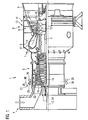
- FIG. 1 shows a gas turbine 1 in a longitudinal partial section. It has inside a rotatably mounted about a rotation axis 2 rotor 3, which is also referred to as a turbine runner. Along the rotor 3 successive an intake 4, a compressor 5, a toroidal annular combustion chamber 6 with a plurality of rotationally symmetrical to each other arranged burners 7, a turbine unit 8 and an exhaust housing 9.
- the annular combustion chamber 6 forms a combustion chamber 17 which communicates with an annular hot gas channel 18.
- There four successive turbine stages 10 form the turbine unit 8. Each turbine stage 10 is formed of two blade rings.
- vanes 13 As seen in the flow direction of a hot gas 11 produced in the annular combustion chamber 6, follows in the hot gas channel 18 in each case one row of vanes 13 a row 14 formed of blades 15.
- the vanes 12 are attached to the stator, whereas the blades 15 a row 14 mounted by a turbine disk on the rotor 3 are.
- a generator or a working machine (not shown) is coupled.
- adjustable inlet blades 19 are provided at the intake housing side entrance of the compressor 5 .
- the inlet blades 19 are arranged radially in the annular flow channel of the compressor 5 and can be rotated about their respective longitudinal axis by a drive device 21 to adjust the gas flow flowing through the gas turbine 1 mass flow.
- a particularly large or a small mass flow can flow through the gas turbine 1 in accordance with requirements.
- all inlet blades 19 are synchronously with constant retention of identical angles adjusted.
- the drive takes place via a housing 26 of the compressor 5 encompassing adjusting ring 26 which is coupled via levers 25 to the inlet blades 19.
- the adjusting ring 26 is rotatable about the central axis 24 in the circumferential direction.
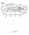
- FIG. 2 shows a section of a cross section through the compressor 5 according to the section line II in the region of the blade carrier 22.
- the blade carrier formed as a blade carrier 22 is substantially circular in cross-section and is encompassed by the concentric to its central axis 24 adjusting ring 26.
- the adjusting ring 26 serves to drive the radially extending inlet blades 19 of the compressor 5, the blades of which form a ring-shaped blade grid in the annular flow channel of the compressor 5 for adjusting the mass flow.
- the device for supporting the adjusting ring 26 can also be used or provided for an adjusting ring 26 which is used to drive adjustable guide vanes of the compressor 5.
- a plurality of one-armed levers 27 distributed over the circumference of the blade carrier 22 are provided, which have a fixed end 28 and a free end 30 opposite this.
- the fixed end 28 of the lever 27 is the carrier side, ie bolted to the blade carrier 22.
- two commercially available screws 42 are used for this purpose, which connects the clamped end 28 rigidly connected to the blade carrier 22.
- a roller 32 is provided, the axis of rotation 34 is aligned parallel to the central axis 24.
- the adjusting ring 26 has on its inner side 36 an endless circumferential annular groove 38, in which each roller 32 of the device engages so that they are on the groove bottom 40 of the annular groove 38 unrolled.
- Each lever 27 is configured in its dimensions such that it presses the rotatably mounted at its free end 30 roller 32 under a bias to the inner side 36 and to the groove bottom 40 of the annular groove 38.
- the dimension h can be specified, which is the distance between the axis of rotation 34 between biased position and relaxed position, d. H. without collar 26, describes.
- the device has an odd number, such as five or seven, such lever 27 to support the adjusting ring 26 concentrically about the central axis 24.
- an even number of levers 27 is also conceivable.
- Each lever 27, also referred to as a roller block, has at least one elongated hole 44 for one or preferably a plurality of screws 42 on its carrier-side fixed end 28.
- the lever 27 is slidable in the tangential direction before tightening, so that the distance considered in the radial direction of the rotation axis 34 and the central axis 24 can be adjusted, whereby the magnitude of the bias, with which the lever 27, the roller 32 at the inside 36 of the adjusting ring 26 or presses against the groove base 40, can be adjusted particularly easily.
- the use of two or more screws 42 prevents rotation of the lever 27 about a radial axis, for example about the longitudinal axis of a screw.
- rollers 32 whose axial width of the width of the annular groove 38 corresponds approximately to prevent tilting of the adjusting ring 26 and its axial displacement reliably. Accordingly, the rollers 32 guided by the groove walls guide the adjusting ring 26.
Landscapes
- Engineering & Computer Science (AREA)
- Mechanical Engineering (AREA)
- General Engineering & Computer Science (AREA)
- Structures Of Non-Positive Displacement Pumps (AREA)
- Processing Of Stones Or Stones Resemblance Materials (AREA)
- Tyre Moulding (AREA)
- Manufacture Of Motors, Generators (AREA)
- Finish Polishing, Edge Sharpening, And Grinding By Specific Grinding Devices (AREA)
- Grinding Of Cylindrical And Plane Surfaces (AREA)
- Coating Apparatus (AREA)
Abstract
Description
Die Erfindung betrifft eine Vorrichtung zur Abstützung eines einen im Wesentlichen kreisförmigen Schaufelträger beabstandet umgreifenden Stellrings, der um eine mit dem Schaufelträger identische Mittelachse in Umfangsrichtung drehbar ist, um sich radial erstreckende Leitschaufeln eines Kranzes einer Turbomaschine zu verstellen.The invention relates to a device for supporting a substantially annular blade carrier encompassing encompassing adjusting ring, which is rotatable about an identical with the blade carrier central axis in the circumferential direction to adjust radially extending vanes of a ring of a turbomachine.
Eine Vorrichtung derartiger Gattung geht beispielsweise aus der
Ebenso ist aus der
Ferner ist bekannt, die Stellringe jeweils über Rollenböcke auf dem Leitschaufelträger radial abzustützen, wobei die Stellringe sich auf den Laufrollen der Rollenböcke in Umfangsrichtung frei bewegen können. Aufgrund der Tatsache, dass die Materialtemperatur des Leitschaufelträgers im Betrieb höher ist als die des außen liegenden Stellrings, entsteht eine radiale Relativbewegung zwischen Leitschaufelträger und dem Stellring. Die Größe der Relativbewegung steigt aufgrund der von Stufe zu Stufe des Leitschaufelträgers steigenden Temperatur an. Um zu verhindern, dass aufgrund dieser Relativbewegung die Belastung der Kontaktstellen zwischen den Rollen und der Lauffläche des Stellrings unzulässig ansteigt, sind die Rollenböcke auf Tellerfederpaketen elastisch gelagert. Die Tellerfederpakete lassen jedoch aufgrund der aus den Reaktionskräften der verstellbaren Schaufeln entstehenden Axialkräfte eine Bewegung des Stellrings in axialer Richtung zu. Dies führt einerseits zu Strömungsverlusten im Verdichter aufgrund der über den Umfang gesehen unsymmetrisch bzw. unterschiedlich verstellten Leitschaufeln des Kranzes sowie andererseits zu Verschleiß an der Abstützung des Stellrings sowie an diesem selber.Furthermore, it is known to radially support the adjusting rings via roller blocks on the guide blade carrier, wherein the adjusting rings can move freely on the rollers of the roller blocks in the circumferential direction. Due to the fact that the material temperature of the vane support during operation is higher than that of the outer adjusting ring, a radial relative movement between the vane support is created and the collar. The amount of relative movement increases due to the temperature rising from stage to stage of the vane carrier. In order to prevent that due to this relative movement, the load on the contact points between the rollers and the tread of the adjusting ring increases inadmissible, the roller blocks are mounted elastically on disc spring assemblies. However, due to the axial forces arising from the reaction forces of the adjustable blades, the disk spring assemblies allow the adjusting ring to move in the axial direction. On the one hand, this leads to flow losses in the compressor due to the circumferentially asymmetrically or differently adjusted guide vanes of the rim and, on the other hand, to wear on the support of the adjusting ring and on the latter itself.
Dementsprechend ist die Aufgabe der vorliegenden Erfindung die Schaffung einer verschleißfreien und zuverlässigen Vorrichtung zur Abstützung eines einen im Wesentlichen kreisförmigen Schaufelträgers beabstandet umgreifenden Stellrings zur Verstellung der sich radial erstreckenden, um ihre Längsachse drehbaren Schaufeln eines Kranzes.Accordingly, the object of the present invention is to provide a wear-resistant and reliable device for supporting a substantially circular blade carrier spaced encompassing adjusting ring for adjusting the radially extending, rotatable about its longitudinal axis blades of a ring.
Gemäß der Erfindung sieht die Vorrichtung zwischen dem Schaufelträger und dem Stellring mehrere, über den Umfang verteilte, jeweils sich tangential erstreckende, einarmige Hebel vor, die jeweils an ihren freien Enden eine drehbare Rolle aufweisen, die am Stellring oder am Schaufelträger in Umfangsrichtung abrollbar sind. Durch die Verwendung der einarmigen Hebel, die in radialer Richtung elastisch sind, wird die bisher in axialer Richtung mögliche Bewegbarkeit des Stellrings unterdrückt, da der einseitig fest eingespannte Hebel in Axialrichtung eine besonders hohe Steifigkeit aufweist. Aufgrund der besonders hohen axialen Steifigkeit können die Hebel die aus den Reaktionskräften der verstellbaren Leitschaufeln entstehenden Axialkräfte ohne zusätzliche konstruktive Elemente, wie zum Beispiel Tellerfedern, Aufnahmen oder Führungselemente, aufgenommen und kompensiert werden.According to the invention, the device provides between the blade carrier and the adjusting ring, distributed over the circumference, each tangentially extending, one-armed lever, each having at their free ends a rotatable roller, which are unrolled on the adjusting ring or on the blade carrier in the circumferential direction. By using the one-armed lever, which are elastic in the radial direction, the previously possible in the axial direction of mobility of the adjusting ring is suppressed because the one-sided firmly clamped lever in the axial direction has a particularly high rigidity. Due to the particularly high axial rigidity, the levers can be absorbed and compensated for the axial forces arising from the reaction forces of the adjustable vanes without additional structural elements, such as disc springs, receptacles or guide elements.
Mit der vorgeschlagenen Ausführung kann somit eine Abstützung für den Stellring angegeben werden, welche lediglich eine in Umfangsrichtung gerichtete Drehbewegung des Stellrings ermöglicht und ein Verkanten bzw. ein teilweises Verschieben in Axialrichtung unterdrückt. Hierdurch wird der Verschleiß am Stellring, an der Befestigung der einarmigen Hebel und an den drehbaren Rollen, welche in Umfangsrichtung am Stellring oder am Schaufelträger abrollbar sind, vermieden. Gleichzeitig ist eine stetig symmetrische Verstellung der Schaufeln eines Kranzes einer Turbomaschine gewährleistet, so dass keine Verluste im die Schaufeln des Kranzes der Turbomaschine umströmenden Medium auftreten. Der Wirkungsgrad der Turbomaschine bleibt dauerhaft aufrecht erhalten.With the proposed embodiment, therefore, a support for the adjusting ring can be specified, which only allows a direction of rotation in the circumferential direction of the adjusting ring and suppresses a tilting or a partial displacement in the axial direction. As a result, the wear on the adjusting ring, on the attachment of the one-armed lever and on the rotatable rollers, which are unrolled in the circumferential direction on the adjusting ring or on the blade carrier avoided. At the same time a steadily symmetrical adjustment of the blades of a ring of a turbomachine is ensured, so that no losses in the blades of the ring of the turbomachine flowing around medium occur. The efficiency of the turbomachine is permanently maintained.
Das der Rolle abgewandte, erste Ende jedes Hebels ist beispielsweise am Schaufelträger fest eingespannt und die an ihm drehgelagerte Rolle ist an der Innenseite des Stellrings abrollbar. Hierdurch wird eine einfache Ausgestaltung erreicht, da der Hebel in Umfangsrichtung tangential am Schaufelträger befestigt ist. Der Hebel kann dann einfach als im Querschnitt rechteckige Strebe oder Biegebalken ausgebildet sein. An den zweiten freien Enden der Hebel ist jeweils die drehgelagerte Rolle vorgesehen, die für diesen Fall an der Innenseite des Stellrings, d.h. an dessen innerer Umfangsfläche abrollbar ist.The role facing away from the first end of each lever is firmly clamped, for example, on the blade carrier and the rotatably mounted on him roller is unrolled on the inside of the adjusting ring. As a result, a simple configuration is achieved, since the lever is fastened tangentially in the circumferential direction on the blade carrier. The lever can then be designed simply as a cross-sectionally rectangular strut or bending beam. At the second free ends of the levers, respectively, the rotatably mounted roller is provided, which in this case is provided on the inside of the adjusting ring, i. can be unrolled on the inner circumferential surface.
Vorteilhafte Ausgestaltungen der Erfindung werden in den Unteransprüchen angegeben.Advantageous embodiments of the invention are specified in the subclaims.
Vorzugsweise ist jede Rolle um eine zur Mittelachse parallele Rollenachse drehbar. Dies ermöglicht die Verwendung von zylindrischen Flächen am Stellring oder am Schaufelträger, an denen ebenfalls zylindrische Rollen abrollbar sind.Preferably, each roller is rotatable about a roller axis parallel to the central axis. This allows the use of cylindrical surfaces on the collar or on the blade carrier, where also cylindrical rollers are unrolled.
Zweckmäßigerweise ist jeder Hebel mit dem Schaufelträger verschraubt, so dass eine besonders einfache Montage und Demontage des Hebels bzw. der Hebel am Schaufelträger möglich ist. Um größere Toleranzen bei der Herstellung der Hebel zu ermöglichen und um eine definierte Vorspannung, welche die am Hebel drehgelagerte Rolle an die Innenseite des Stellrings oder an den Schaufelträger presst, einzustellen, weist jeder Hebel mindestens ein sich in Tangentialrichtung erstreckendes Langloch zur Aufnahme der Verschraubung auf. Dadurch kann die gewünschte Vorspannung des Hebels stufenlos eingestellt werden, da die freie, biegsame Länge jedes Hebels zwischen den seinen Enden variiert werden kann.Conveniently, each lever is bolted to the blade carrier, so that a particularly simple assembly and disassembly of the lever or the lever on the blade carrier is possible. To allow greater tolerances in the manufacture of the lever and to set a defined preload, which presses the roller rotatably mounted on the lever to the inside of the adjusting ring or to the blade carrier, each lever has at least one elongated hole extending in the tangential direction for receiving the screw connection. Thereby, the desired bias of the lever can be adjusted continuously, since the free, flexible length of each lever between its ends can be varied.
Um ein Abrutschen der Rollen von der Innenseite des Stellrings zu verhindern, ist an der Innenseite des Stellrings eine endlos umlaufende Ringnut mit einem Nutgrund vorgesehen, an der die Rollen abrollbar sind. Die Nutwände der Ringnut führen die Rollen und verhindern so das Abrutschen der Rollen von der Lauffläche.In order to prevent slippage of the rollers from the inside of the adjusting ring, an endlessly circumferential annular groove is provided with a groove base on the inside of the adjusting ring, on which the rollers are unrolled. The groove walls of the annular groove guide the rollers and thus prevent the slipping of the rollers of the tread.
Besonders vorteilhaft ist die Vorrichtung zur Abstützung eines Stellrings bei einer Turbomaschine, beispielsweise bei einem ggf. auch mehrstufigen Axialverdichter einsetzbar, wobei der Antrieb zum Verstellen der Schaufeln einen den Schaufelträger umgreifenden Stellring aufweist, der nach einem der Ansprüche 1 bis 7 abgestützt ist.Particularly advantageously, the device for supporting an adjusting ring in a turbomachine, for example in an optionally multi-stage axial compressor used, the drive for adjusting the blades has a blade carrier encompassing adjusting ring which is supported according to one of claims 1 to 7.
Die Schaufeln können als Leitschaufeln oder auch als verstellbare Einlassschaufeln eines Verdichters ausgebildet sein. Ebenso könnte die Erfindung in einer Dampfturbine angewendet werden, die verstellbare Einlass- oder Leitschaufeln aufweist.The blades may be formed as guide vanes or as adjustable inlet blades of a compressor. Similarly, the invention could be applied to a steam turbine having variable inlet or stator vanes.
Die weitere Erläuterung der Erfindung erfolgt anhand des in der Zeichnung dargestellten Ausführungsbeispiels.The further explanation of the invention is based on the embodiment shown in the drawing.
Im Einzelnen zeigt
- FIG 1
- eine Gasturbine mit einem Verdichter in einem Längsteilquerschnitt und
- FIG 2
- einen einseitig eingespannten Rollenbock zur Abstützung des Stellrings.
- FIG. 1
- a gas turbine with a compressor in a longitudinal part cross-section and
- FIG. 2
- a cantilevered roller block for supporting the adjusting ring.
Am ansauggehäuseseitigen Eingang des Verdichters 5 sind verstellbare Einlassschaufeln 19 vorgesehen. Die Einlassschaufeln 19 sind strahlenförmig im ringförmigen Strömungskanal des Verdichters 5 angeordnet und können um ihre jeweilige Längsachse von einer Antriebsvorrichtung 21 gedreht werden, um den die Gasturbine 1 durchströmenden Massenstrom einzustellen. Je nach Anstellwinkel der Einlassschaufeln 19 kann ein besonders großer oder ein kleiner Massenstrom die Gasturbine 1 anforderungsgerecht durchströmen. Um Strömungsverluste in der angesaugten Umgebungsluft zu verhindern und um eine Schwingungsanregung von unmittelbar stromab der Einlassschaufeln 19 sich drehenden Laufschaufeln 15 zu verhindern, welche bei einer über den Umfang gesehen ungleichmäßig starken Anströmung der Laufschaufeln 15 erfolgt, werden alle Einlassschaufeln 19 synchron unter stetiger Beibehaltung identischer Anstellwinkel verstellt.At the intake housing side entrance of the compressor 5
Der Antrieb erfolgt über einen das Gehäuse des Verdichters 5 umgreifenden Stellring 26, welcher über Hebel 25 an die Einlassschaufeln 19 gekoppelt ist. Zur bedarfsgerechten Verstellung der Anstellwinkel der Einlassleitschaufeln 19 ist der Stellring 26 in Umfangrichtung um die Mittelachse 24 drehbar.The drive takes place via a
Da der Gegenstand der Verstellung der Schaufeln in Abhängigkeit von der in Umfangsrichtung gerichteten Drehung des Stellrings nicht Gegenstand der Erfindung ist, wird auf diesen Antriebsmechanismus nicht weiter eingegangen. Beispielsweise könnte dieser gemäß
Die Vorrichtung zur Abstützung des Stellrings 26 kann auch für einen Stellring 26 eingesetzt bzw. vorgesehen sein, welcher zum Antrieb von verstellbaren Leitschaufeln des Verdichters 5 genutzt wird.The device for supporting the adjusting
Um den Stellring 26 konzentrisch um die Mittelachse 24 des Verdichters 5 zu lagern, sind mehrere über den Umfang des Schaufelträgers 22 verteilte einarmige Hebel 27 vorgesehen, die ein fest eingespanntes Ende 28 und ein diesem gegenüber liegendes freie Ende 30 aufweisen. Das feste Ende 28 des Hebels 27 ist trägerseitig, d.h. am Schaufelträger 22 verschraubt. Im gezeigten Ausführungsbeispiel werden hierzu zwei handelsübliche Schrauben 42 eingesetzt, die das eingespannte Ende 28 starr mit dem Schaufelträger 22 verbindet. Am freien Ende 30 des Hebels 27 ist eine Rolle 32 vorgesehen, deren Drehachse 34 parallel zur Mittelachse 24 ausgerichtet ist.In order to store the adjusting ring concentrically around the
Der Stellring 26 weist an seiner Innenseite 36 eine endlos umlaufende Ringnut 38 auf, in der jede Rolle 32 der Vorrichtung so eingreift, dass diese am Nutgrund 40 der Ringnut 38 abrollbar sind.The adjusting
Jeder Hebel 27 ist in seinen Dimensionen derartig ausgestaltet, dass dieser die an seinem freien Ende 30 drehgelagerte Rolle 32 unter einer Vorspannung an die Innenseite 36 bzw. an den Nutgrund 40 der Ringnut 38 presst. Als Maß für die Vorspannkraft kann das Maß h angegeben werden, welches den Abstand der Drehachse 34 zwischen vorgespannter Position und entspannter Position, d. h. ohne Stellring 26, beschreibt.Each
Vorzugsweise weist die Vorrichtung eine ungerade Anzahl, beispielsweise fünf oder sieben, derartiger Hebel 27 auf, um den Stellring 26 konzentrisch um die Mittelachse 24 zu lagern. Eine gerade Anzahl an Hebeln 27 ist jedoch auch denkbar.Preferably, the device has an odd number, such as five or seven,
Jeder auch als Rollenbock bezeichneter Hebel 27 weist an seinem trägerseitig festen Ende 28 mindestens ein Langloch 44 für ein oder vorzugsweise mehrere Schrauben 42 auf. Durch die Verwendung von Langlöchern 44 ist der Hebel 27 in Tangentialrichtung vor dem Festschrauben verschiebbar, so dass der in Radialrichtung betrachtete Abstand der Drehachse 34 und der Mittelachse 24 eingestellt werden kann, wodurch die Größe der Vorspannung, mit welcher der Hebel 27 die Rolle 32 an die Innenseite 36 des Stellrings 26 bzw. an den Nutgrund 40 anpresst, besonders einfach eingestellt werden kann. Insbesondere die Verwendung von zwei oder mehreren Schrauben 42 verhindert ein Verdrehen des Hebels 27 um eine radiale Achse, beispielsweise um die Längsachse einer Schraube. Üblicherweise weisen alle über den Umfang verteilten Hebel 27 die gleiche Vorspannung auf, um den Stellring 26 konzentrisch abzustützen.Each
Ist der Hebel 27 derart am Schaufelträger 22 verschraubt, dass das Ende 44a des Langlochs, welcher der Rolle zugewandt ist, an der rechts dargestellten Schraube anliegt, so ist die Vorspannung geringer als bei der Position, bei der das äußere Ende 44b des Langlochs 44 an der links dargestellten Schraube anliegt.If the
Aufgrund der trägerseitig fest eingespannten Hebel 27 verhindern diese eine in axialer Richtung auftretende Verschiebung oder Bewegung des Stellrings 26, was aufgrund der Reaktionskräfte des die Schaufeln umströmenden Mediums bisher erfolgen konnte.Due to the carrier-side firmly clamped
Zusätzlich verhindern die in einer endlos umlaufenden Ringnut 38 geführten Rollen 32, deren axiale Breite der Breite der Ringnut 38 in etwa entspricht, ein Verkippen des Stellrings 26 bzw. dessen axiale Verschiebung zuverlässig. Dementsprechend führen die von den Nutwänden geführten Rollen 32 den Stellring 26.In addition, the guided in an endless circumferential
Claims (9)
- Device for support of an adjusting ring (26) which encompasses at a distance a basically circular blade carrier (22),
which adjusting ring is rotatable in the circumferential direction around a center axis (24) which is identical with the blade carrier (22),
in order to adjust radially extending blades of a ring of a turbo-engine,
wherein a plurality of levers (27) are provided between the blade carrier (22) and the adjusting ring (26), which levers are distributed over the circumference, extend tangentially in each case, and which on their free ends (30) have a rotatable roller (32) in each case, which are rollable in the circumferential direction on the adjusting ring (26) or on the blade carrier (22),
characterized in that
the lever (27) is tightly clamped on one side by its end facing away from the roller (32). - Device according to claim 1,
in which each roller (32) is rotatable around a rotational axis (34) which is parallel to the center axis (24). - Device according to claim 1 or 2,
in which each lever (27) is clamped on the blade carrier (22) and the roller (32), which is rotatably mounted on it, is rollable on the inner side (36) of the adjusting ring (26). - Device according to claim 3,
in which each lever (27) is screwed to the blade carrier (22) . - Device according to claim 3 or 4,
in which each lever (27) has at least one elongated hole (44), which extends in the tangential direction, for accommodating screws (42). - Device according to one of the preceding claims,
in which each lever (27) presses the roller (32), which is rotatably mounted on it, under a pretensioning onto the inner side (36) of the adjusting ring (26) or onto the blade carrier (22). - Device according to one of the preceding claims,
in which the adjusting ring (26) on the inner side (36) has an encompassing annular groove (38) with a groove base (40) upon which the rollers (32) are rollable. - Turbo-engine with a blade carrier (22),
which has blades which are adjustable around its longitudinal axis, wherein the drive for adjusting the blades has an adjusting ring (26) which encompasses the blade carrier (22), which adjusting ring is supported according to one of claims 1 to 7. - Turbo-engine according to claim 8,
in which the blades are formed as stator blades which are adjustably installed on the stator blade carrier (22), or formed as adjustable inlet guide vanes.
Priority Applications (4)
| Application Number | Priority Date | Filing Date | Title |
|---|---|---|---|
| EP06000027A EP1803902B1 (en) | 2006-01-02 | 2006-01-02 | Device for supporting an adjusting ring encompassing at a certain distance a circular blade support |
| AT06000027T ATE403798T1 (en) | 2006-01-02 | 2006-01-02 | DEVICE FOR SUPPORTING AN ADJUSTING RING AROUND A CIRCULAR BLADE CARRIER |
| DE502006001275T DE502006001275D1 (en) | 2006-01-02 | 2006-01-02 | Device for supporting a circular blade carrier spaced encompassing adjusting ring |
| US11/649,141 US7828516B2 (en) | 2006-01-02 | 2007-01-03 | Device for support of an adjusting ring which encompasses at a distance a circular blade carrier |
Applications Claiming Priority (1)
| Application Number | Priority Date | Filing Date | Title |
|---|---|---|---|
| EP06000027A EP1803902B1 (en) | 2006-01-02 | 2006-01-02 | Device for supporting an adjusting ring encompassing at a certain distance a circular blade support |
Publications (2)
| Publication Number | Publication Date |
|---|---|
| EP1803902A1 EP1803902A1 (en) | 2007-07-04 |
| EP1803902B1 true EP1803902B1 (en) | 2008-08-06 |
Family
ID=36950203
Family Applications (1)
| Application Number | Title | Priority Date | Filing Date |
|---|---|---|---|
| EP06000027A Not-in-force EP1803902B1 (en) | 2006-01-02 | 2006-01-02 | Device for supporting an adjusting ring encompassing at a certain distance a circular blade support |
Country Status (4)
| Country | Link |
|---|---|
| US (1) | US7828516B2 (en) |
| EP (1) | EP1803902B1 (en) |
| AT (1) | ATE403798T1 (en) |
| DE (1) | DE502006001275D1 (en) |
Families Citing this family (16)
| Publication number | Priority date | Publication date | Assignee | Title |
|---|---|---|---|---|
| WO2011066166A1 (en) * | 2009-11-30 | 2011-06-03 | Barber Gerald L | Wind turbine with adjustable electrical generator |
| IT1401664B1 (en) | 2010-08-31 | 2013-08-02 | Nuova Pignone S R L | CENTERING DEVICE AND GUIDE RING SYSTEM. |
| DE102011086031B4 (en) * | 2010-11-23 | 2016-02-04 | Bosch Mahle Turbo Systems Gmbh & Co. Kg | Variable turbine geometry |
| US9284851B2 (en) * | 2012-02-21 | 2016-03-15 | Mitsubishi Heavy Industries, Ltd. | Axial-flow fluid machine, and variable vane drive device thereof |
| US9651053B2 (en) | 2014-01-24 | 2017-05-16 | Pratt & Whitney Canada Corp. | Bleed valve |
| US10125622B2 (en) | 2015-08-27 | 2018-11-13 | Rolls-Royce North American Technologies Inc. | Splayed inlet guide vanes |
| US10267160B2 (en) | 2015-08-27 | 2019-04-23 | Rolls-Royce North American Technologies Inc. | Methods of creating fluidic barriers in turbine engines |
| US9976514B2 (en) | 2015-08-27 | 2018-05-22 | Rolls-Royce North American Technologies, Inc. | Propulsive force vectoring |
| US10280872B2 (en) | 2015-08-27 | 2019-05-07 | Rolls-Royce North American Technologies Inc. | System and method for a fluidic barrier from the upstream splitter |
| US9915149B2 (en) | 2015-08-27 | 2018-03-13 | Rolls-Royce North American Technologies Inc. | System and method for a fluidic barrier on the low pressure side of a fan blade |
| US20170057649A1 (en) | 2015-08-27 | 2017-03-02 | Edward C. Rice | Integrated aircraft propulsion system |
| US10267159B2 (en) | 2015-08-27 | 2019-04-23 | Rolls-Royce North America Technologies Inc. | System and method for creating a fluidic barrier with vortices from the upstream splitter |
| US10233869B2 (en) | 2015-08-27 | 2019-03-19 | Rolls Royce North American Technologies Inc. | System and method for creating a fluidic barrier from the leading edge of a fan blade |
| US10718221B2 (en) | 2015-08-27 | 2020-07-21 | Rolls Royce North American Technologies Inc. | Morphing vane |
| KR102572313B1 (en) | 2017-09-25 | 2023-08-29 | 존슨 컨트롤스 테크놀러지 컴퍼니 | Compact variable geometry diffuser mechanism |
| CN114961882A (en) * | 2021-02-26 | 2022-08-30 | 中国航发商用航空发动机有限责任公司 | Adjustable stator blade angle control device |
Family Cites Families (13)
| Publication number | Priority date | Publication date | Assignee | Title |
|---|---|---|---|---|
| US3558237A (en) * | 1969-06-25 | 1971-01-26 | Gen Motors Corp | Variable turbine nozzles |
| US3736070A (en) * | 1971-06-22 | 1973-05-29 | Curtiss Wright Corp | Variable stator blade assembly for axial flow, fluid expansion engine |
| DE2253030A1 (en) * | 1972-10-28 | 1974-05-09 | Sljusarew | DEVICE FOR BLADE ADJUSTMENT OF THE CONTROL UNIT OF A FLOW MACHINE |
| CH582823A5 (en) * | 1975-03-06 | 1976-12-15 | Bbc Brown Boveri & Cie | |
| US3990809A (en) * | 1975-07-24 | 1976-11-09 | United Technologies Corporation | High ratio actuation linkage |
| CA1034509A (en) * | 1975-10-14 | 1978-07-11 | John Korta | Vane rotator assembly for a gas turbine |
| US4035101A (en) * | 1976-03-24 | 1977-07-12 | Westinghouse Electric Corporation | Gas turbine nozzle vane adjusting mechanism |
| DE3913102C1 (en) * | 1989-04-21 | 1990-05-31 | Mtu Muenchen Gmbh | |
| US5538214A (en) * | 1994-07-27 | 1996-07-23 | Sinila; Alexander | Locking accessory support apparatus |
| US5549448A (en) | 1995-02-08 | 1996-08-27 | United Technolgies Corporation | Variable stator vane linkage system and method |
| SE519353C2 (en) * | 2000-11-15 | 2003-02-18 | Volvo Aero Corp | Stator for a gas turbine |
| EP1524413A2 (en) | 2003-10-15 | 2005-04-20 | United Technologies Corporation | Variable vane electro-graphitic bushing liner |
| DE10351202A1 (en) | 2003-11-03 | 2005-06-02 | Mtu Aero Engines Gmbh | Device for adjusting vanes |
-
2006
- 2006-01-02 EP EP06000027A patent/EP1803902B1/en not_active Not-in-force
- 2006-01-02 AT AT06000027T patent/ATE403798T1/en not_active IP Right Cessation
- 2006-01-02 DE DE502006001275T patent/DE502006001275D1/en active Active
-
2007
- 2007-01-03 US US11/649,141 patent/US7828516B2/en not_active Expired - Fee Related
Also Published As
| Publication number | Publication date |
|---|---|
| ATE403798T1 (en) | 2008-08-15 |
| US20070154301A1 (en) | 2007-07-05 |
| US7828516B2 (en) | 2010-11-09 |
| EP1803902A1 (en) | 2007-07-04 |
| DE502006001275D1 (en) | 2008-09-18 |
Similar Documents
| Publication | Publication Date | Title |
|---|---|---|
| EP1803902B1 (en) | Device for supporting an adjusting ring encompassing at a certain distance a circular blade support | |
| DE102012213227B3 (en) | Blade ring for a turbo machine | |
| EP1394364B1 (en) | Turbocharger and annular guide conduit therefor | |
| DE102012007129A1 (en) | Guide vane adjusting a gas turbine | |
| EP3000984B1 (en) | Turbine vane adjustment device for a gas turbine | |
| DE4031478A1 (en) | BLADE TIP GAP WIDTH CONTROL DEVICE WITH CAM ACTUATED SHEET RING SEGMENT POSITIONING DEVICE | |
| DE4028330A1 (en) | Mechanical blade tip clearance control - has shroud hanger disposed between casing and opening in casing | |
| EP2362070A1 (en) | Drive device for pivoting adjustable vanes of a turbomachine | |
| DE19703033A1 (en) | Exhaust gas turbine of a turbocharger | |
| WO2005028812A1 (en) | Labyrinth seal in a stationary gas turbine | |
| EP2617947B1 (en) | Aircraft gas turbine engine with adjustable fan | |
| EP2386726B1 (en) | Channel wall section for a ring-shaped flow channel of an axial turbomaschine with blade tip gap adjustment, corresponding axial compressor and gas turbine | |
| EP1860284A1 (en) | Casings assembling | |
| EP2233701A1 (en) | Axial turbomachine with axially displaceable vane carrier | |
| EP2342425A1 (en) | Gas turbine with securing plate between blade base and disk | |
| EP2492452A1 (en) | Method for constructing a turbo machine | |
| EP2078137A1 (en) | Rotor for a turbo-machine | |
| EP2591213A2 (en) | Compressor and corresponding gas turbine | |
| EP2730751B1 (en) | Vane adjustment device for a gas turbine | |
| EP3176386B1 (en) | Inner shroud assembly, corresponding inner shroud, inner casing and turbomachine | |
| WO2009109430A1 (en) | Sealing arrangement and gas turbine | |
| CH704825A1 (en) | Turbomachinery rotor. | |
| DE102011102315A1 (en) | Gas turbine balancing device for use in turbo-engine of aircraft, has balancing rings rotatable by tool that is operated in mounted condition of gas turbine and fixed relative to each other and relative to groove by fixing device | |
| WO2011088819A2 (en) | Housing system for an axial turbomachine | |
| EP1783325B1 (en) | Fastening arrangement of a pipe on a peripheral surface |
Legal Events
| Date | Code | Title | Description |
|---|---|---|---|
| PUAI | Public reference made under article 153(3) epc to a published international application that has entered the european phase |
Free format text: ORIGINAL CODE: 0009012 |
|
| AK | Designated contracting states |
Kind code of ref document: A1 Designated state(s): AT BE BG CH CY CZ DE DK EE ES FI FR GB GR HU IE IS IT LI LT LU LV MC NL PL PT RO SE SI SK TR |
|
| AX | Request for extension of the european patent |
Extension state: AL BA HR MK YU |
|
| 17P | Request for examination filed |
Effective date: 20071022 |
|
| GRAP | Despatch of communication of intention to grant a patent |
Free format text: ORIGINAL CODE: EPIDOSNIGR1 |
|
| AKX | Designation fees paid |
Designated state(s): AT BE BG CH CY CZ DE DK EE ES FI FR GB GR HU IE IS IT LI LT LU LV MC NL PL PT RO SE SI SK TR |
|
| GRAS | Grant fee paid |
Free format text: ORIGINAL CODE: EPIDOSNIGR3 |
|
| GRAA | (expected) grant |
Free format text: ORIGINAL CODE: 0009210 |
|
| AK | Designated contracting states |
Kind code of ref document: B1 Designated state(s): AT BE BG CH CY CZ DE DK EE ES FI FR GB GR HU IE IS IT LI LT LU LV MC NL PL PT RO SE SI SK TR |
|
| REG | Reference to a national code |
Ref country code: GB Ref legal event code: FG4D Free format text: NOT ENGLISH |
|
| REG | Reference to a national code |
Ref country code: CH Ref legal event code: NV Representative=s name: SIEMENS SCHWEIZ AG Ref country code: CH Ref legal event code: EP |
|
| REG | Reference to a national code |
Ref country code: IE Ref legal event code: FG4D Free format text: LANGUAGE OF EP DOCUMENT: GERMAN |
|
| REF | Corresponds to: |
Ref document number: 502006001275 Country of ref document: DE Date of ref document: 20080918 Kind code of ref document: P |
|
| PG25 | Lapsed in a contracting state [announced via postgrant information from national office to epo] |
Ref country code: LT Free format text: LAPSE BECAUSE OF FAILURE TO SUBMIT A TRANSLATION OF THE DESCRIPTION OR TO PAY THE FEE WITHIN THE PRESCRIBED TIME-LIMIT Effective date: 20080806 Ref country code: IS Free format text: LAPSE BECAUSE OF FAILURE TO SUBMIT A TRANSLATION OF THE DESCRIPTION OR TO PAY THE FEE WITHIN THE PRESCRIBED TIME-LIMIT Effective date: 20081206 Ref country code: NL Free format text: LAPSE BECAUSE OF FAILURE TO SUBMIT A TRANSLATION OF THE DESCRIPTION OR TO PAY THE FEE WITHIN THE PRESCRIBED TIME-LIMIT Effective date: 20080806 |
|
| PG25 | Lapsed in a contracting state [announced via postgrant information from national office to epo] |
Ref country code: LV Free format text: LAPSE BECAUSE OF FAILURE TO SUBMIT A TRANSLATION OF THE DESCRIPTION OR TO PAY THE FEE WITHIN THE PRESCRIBED TIME-LIMIT Effective date: 20080806 Ref country code: FI Free format text: LAPSE BECAUSE OF FAILURE TO SUBMIT A TRANSLATION OF THE DESCRIPTION OR TO PAY THE FEE WITHIN THE PRESCRIBED TIME-LIMIT Effective date: 20080806 Ref country code: ES Free format text: LAPSE BECAUSE OF FAILURE TO SUBMIT A TRANSLATION OF THE DESCRIPTION OR TO PAY THE FEE WITHIN THE PRESCRIBED TIME-LIMIT Effective date: 20081117 Ref country code: SI Free format text: LAPSE BECAUSE OF FAILURE TO SUBMIT A TRANSLATION OF THE DESCRIPTION OR TO PAY THE FEE WITHIN THE PRESCRIBED TIME-LIMIT Effective date: 20080806 |
|
| REG | Reference to a national code |
Ref country code: IE Ref legal event code: FD4D |
|
| REG | Reference to a national code |
Ref country code: CH Ref legal event code: PCAR Free format text: SIEMENS SCHWEIZ AG;INTELLECTUAL PROPERTY FREILAGERSTRASSE 40;8047 ZUERICH (CH) |
|
| PG25 | Lapsed in a contracting state [announced via postgrant information from national office to epo] |
Ref country code: BG Free format text: LAPSE BECAUSE OF FAILURE TO SUBMIT A TRANSLATION OF THE DESCRIPTION OR TO PAY THE FEE WITHIN THE PRESCRIBED TIME-LIMIT Effective date: 20081106 Ref country code: DK Free format text: LAPSE BECAUSE OF FAILURE TO SUBMIT A TRANSLATION OF THE DESCRIPTION OR TO PAY THE FEE WITHIN THE PRESCRIBED TIME-LIMIT Effective date: 20080806 Ref country code: IE Free format text: LAPSE BECAUSE OF FAILURE TO SUBMIT A TRANSLATION OF THE DESCRIPTION OR TO PAY THE FEE WITHIN THE PRESCRIBED TIME-LIMIT Effective date: 20080806 |
|
| PG25 | Lapsed in a contracting state [announced via postgrant information from national office to epo] |
Ref country code: CZ Free format text: LAPSE BECAUSE OF FAILURE TO SUBMIT A TRANSLATION OF THE DESCRIPTION OR TO PAY THE FEE WITHIN THE PRESCRIBED TIME-LIMIT Effective date: 20080806 Ref country code: SK Free format text: LAPSE BECAUSE OF FAILURE TO SUBMIT A TRANSLATION OF THE DESCRIPTION OR TO PAY THE FEE WITHIN THE PRESCRIBED TIME-LIMIT Effective date: 20080806 Ref country code: RO Free format text: LAPSE BECAUSE OF FAILURE TO SUBMIT A TRANSLATION OF THE DESCRIPTION OR TO PAY THE FEE WITHIN THE PRESCRIBED TIME-LIMIT Effective date: 20080806 Ref country code: PT Free format text: LAPSE BECAUSE OF FAILURE TO SUBMIT A TRANSLATION OF THE DESCRIPTION OR TO PAY THE FEE WITHIN THE PRESCRIBED TIME-LIMIT Effective date: 20090106 |
|
| PLBE | No opposition filed within time limit |
Free format text: ORIGINAL CODE: 0009261 |
|
| STAA | Information on the status of an ep patent application or granted ep patent |
Free format text: STATUS: NO OPPOSITION FILED WITHIN TIME LIMIT |
|
| 26N | No opposition filed |
Effective date: 20090507 |
|
| PG25 | Lapsed in a contracting state [announced via postgrant information from national office to epo] |
Ref country code: EE Free format text: LAPSE BECAUSE OF FAILURE TO SUBMIT A TRANSLATION OF THE DESCRIPTION OR TO PAY THE FEE WITHIN THE PRESCRIBED TIME-LIMIT Effective date: 20080806 |
|
| PG25 | Lapsed in a contracting state [announced via postgrant information from national office to epo] |
Ref country code: MC Free format text: LAPSE BECAUSE OF NON-PAYMENT OF DUE FEES Effective date: 20090131 |
|
| PG25 | Lapsed in a contracting state [announced via postgrant information from national office to epo] |
Ref country code: SE Free format text: LAPSE BECAUSE OF FAILURE TO SUBMIT A TRANSLATION OF THE DESCRIPTION OR TO PAY THE FEE WITHIN THE PRESCRIBED TIME-LIMIT Effective date: 20081106 |
|
| PG25 | Lapsed in a contracting state [announced via postgrant information from national office to epo] |
Ref country code: BE Free format text: LAPSE BECAUSE OF NON-PAYMENT OF DUE FEES Effective date: 20090131 |
|
| PG25 | Lapsed in a contracting state [announced via postgrant information from national office to epo] |
Ref country code: PL Free format text: LAPSE BECAUSE OF FAILURE TO SUBMIT A TRANSLATION OF THE DESCRIPTION OR TO PAY THE FEE WITHIN THE PRESCRIBED TIME-LIMIT Effective date: 20080806 |
|
| PG25 | Lapsed in a contracting state [announced via postgrant information from national office to epo] |
Ref country code: AT Free format text: LAPSE BECAUSE OF NON-PAYMENT OF DUE FEES Effective date: 20090102 |
|
| PG25 | Lapsed in a contracting state [announced via postgrant information from national office to epo] |
Ref country code: GR Free format text: LAPSE BECAUSE OF FAILURE TO SUBMIT A TRANSLATION OF THE DESCRIPTION OR TO PAY THE FEE WITHIN THE PRESCRIBED TIME-LIMIT Effective date: 20081107 |
|
| PG25 | Lapsed in a contracting state [announced via postgrant information from national office to epo] |
Ref country code: LU Free format text: LAPSE BECAUSE OF NON-PAYMENT OF DUE FEES Effective date: 20090102 |
|
| PG25 | Lapsed in a contracting state [announced via postgrant information from national office to epo] |
Ref country code: HU Free format text: LAPSE BECAUSE OF FAILURE TO SUBMIT A TRANSLATION OF THE DESCRIPTION OR TO PAY THE FEE WITHIN THE PRESCRIBED TIME-LIMIT Effective date: 20090207 |
|
| PG25 | Lapsed in a contracting state [announced via postgrant information from national office to epo] |
Ref country code: TR Free format text: LAPSE BECAUSE OF FAILURE TO SUBMIT A TRANSLATION OF THE DESCRIPTION OR TO PAY THE FEE WITHIN THE PRESCRIBED TIME-LIMIT Effective date: 20080806 |
|
| PG25 | Lapsed in a contracting state [announced via postgrant information from national office to epo] |
Ref country code: CY Free format text: LAPSE BECAUSE OF FAILURE TO SUBMIT A TRANSLATION OF THE DESCRIPTION OR TO PAY THE FEE WITHIN THE PRESCRIBED TIME-LIMIT Effective date: 20080806 |
|
| REG | Reference to a national code |
Ref country code: FR Ref legal event code: PLFP Year of fee payment: 11 |
|
| PGFP | Annual fee paid to national office [announced via postgrant information from national office to epo] |
Ref country code: CH Payment date: 20160404 Year of fee payment: 11 |
|
| REG | Reference to a national code |
Ref country code: FR Ref legal event code: PLFP Year of fee payment: 12 |
|
| PGFP | Annual fee paid to national office [announced via postgrant information from national office to epo] |
Ref country code: DE Payment date: 20170320 Year of fee payment: 12 Ref country code: FR Payment date: 20170117 Year of fee payment: 12 |
|
| PGFP | Annual fee paid to national office [announced via postgrant information from national office to epo] |
Ref country code: GB Payment date: 20170109 Year of fee payment: 12 |
|
| PGFP | Annual fee paid to national office [announced via postgrant information from national office to epo] |
Ref country code: IT Payment date: 20170127 Year of fee payment: 12 |
|
| REG | Reference to a national code |
Ref country code: CH Ref legal event code: PL |
|
| PG25 | Lapsed in a contracting state [announced via postgrant information from national office to epo] |
Ref country code: LI Free format text: LAPSE BECAUSE OF NON-PAYMENT OF DUE FEES Effective date: 20170131 Ref country code: CH Free format text: LAPSE BECAUSE OF NON-PAYMENT OF DUE FEES Effective date: 20170131 |
|
| REG | Reference to a national code |
Ref country code: DE Ref legal event code: R119 Ref document number: 502006001275 Country of ref document: DE |
|
| GBPC | Gb: european patent ceased through non-payment of renewal fee |
Effective date: 20180102 |
|
| PG25 | Lapsed in a contracting state [announced via postgrant information from national office to epo] |
Ref country code: DE Free format text: LAPSE BECAUSE OF NON-PAYMENT OF DUE FEES Effective date: 20180801 Ref country code: FR Free format text: LAPSE BECAUSE OF NON-PAYMENT OF DUE FEES Effective date: 20180131 |
|
| REG | Reference to a national code |
Ref country code: FR Ref legal event code: ST Effective date: 20180928 |
|
| PG25 | Lapsed in a contracting state [announced via postgrant information from national office to epo] |
Ref country code: GB Free format text: LAPSE BECAUSE OF NON-PAYMENT OF DUE FEES Effective date: 20180102 |
|
| PG25 | Lapsed in a contracting state [announced via postgrant information from national office to epo] |
Ref country code: IT Free format text: LAPSE BECAUSE OF NON-PAYMENT OF DUE FEES Effective date: 20180102 |