EP2730751B1 - Vane adjustment device for a gas turbine - Google Patents
Vane adjustment device for a gas turbine Download PDFInfo
- Publication number
- EP2730751B1 EP2730751B1 EP13191938.3A EP13191938A EP2730751B1 EP 2730751 B1 EP2730751 B1 EP 2730751B1 EP 13191938 A EP13191938 A EP 13191938A EP 2730751 B1 EP2730751 B1 EP 2730751B1
- Authority
- EP
- European Patent Office
- Prior art keywords
- lever
- accordance
- crankshaft
- gas turbine
- actuator
- Prior art date
- Legal status (The legal status is an assumption and is not a legal conclusion. Google has not performed a legal analysis and makes no representation as to the accuracy of the status listed.)
- Not-in-force
Links
Images


Classifications
-
- F—MECHANICAL ENGINEERING; LIGHTING; HEATING; WEAPONS; BLASTING
- F01—MACHINES OR ENGINES IN GENERAL; ENGINE PLANTS IN GENERAL; STEAM ENGINES
- F01D—NON-POSITIVE DISPLACEMENT MACHINES OR ENGINES, e.g. STEAM TURBINES
- F01D9/00—Stators
- F01D9/02—Nozzles; Nozzle boxes; Stator blades; Guide conduits, e.g. individual nozzles
- F01D9/04—Nozzles; Nozzle boxes; Stator blades; Guide conduits, e.g. individual nozzles forming ring or sector
- F01D9/045—Nozzles; Nozzle boxes; Stator blades; Guide conduits, e.g. individual nozzles forming ring or sector for radial flow machines or engines
-
- F—MECHANICAL ENGINEERING; LIGHTING; HEATING; WEAPONS; BLASTING
- F01—MACHINES OR ENGINES IN GENERAL; ENGINE PLANTS IN GENERAL; STEAM ENGINES
- F01D—NON-POSITIVE DISPLACEMENT MACHINES OR ENGINES, e.g. STEAM TURBINES
- F01D17/00—Regulating or controlling by varying flow
- F01D17/10—Final actuators
- F01D17/12—Final actuators arranged in stator parts
- F01D17/14—Final actuators arranged in stator parts varying effective cross-sectional area of nozzles or guide conduits
- F01D17/16—Final actuators arranged in stator parts varying effective cross-sectional area of nozzles or guide conduits by means of nozzle vanes
- F01D17/162—Final actuators arranged in stator parts varying effective cross-sectional area of nozzles or guide conduits by means of nozzle vanes for axial flow, i.e. the vanes turning around axes which are essentially perpendicular to the rotor centre line
-
- F—MECHANICAL ENGINEERING; LIGHTING; HEATING; WEAPONS; BLASTING
- F02—COMBUSTION ENGINES; HOT-GAS OR COMBUSTION-PRODUCT ENGINE PLANTS
- F02C—GAS-TURBINE PLANTS; AIR INTAKES FOR JET-PROPULSION PLANTS; CONTROLLING FUEL SUPPLY IN AIR-BREATHING JET-PROPULSION PLANTS
- F02C9/00—Controlling gas-turbine plants; Controlling fuel supply in air- breathing jet-propulsion plants
- F02C9/16—Control of working fluid flow
- F02C9/20—Control of working fluid flow by throttling; by adjusting vanes
-
- F—MECHANICAL ENGINEERING; LIGHTING; HEATING; WEAPONS; BLASTING
- F04—POSITIVE - DISPLACEMENT MACHINES FOR LIQUIDS; PUMPS FOR LIQUIDS OR ELASTIC FLUIDS
- F04D—NON-POSITIVE-DISPLACEMENT PUMPS
- F04D29/00—Details, component parts, or accessories
- F04D29/40—Casings; Connections of working fluid
- F04D29/52—Casings; Connections of working fluid for axial pumps
- F04D29/54—Fluid-guiding means, e.g. diffusers
- F04D29/56—Fluid-guiding means, e.g. diffusers adjustable
- F04D29/563—Fluid-guiding means, e.g. diffusers adjustable specially adapted for elastic fluid pumps
-
- F—MECHANICAL ENGINEERING; LIGHTING; HEATING; WEAPONS; BLASTING
- F05—INDEXING SCHEMES RELATING TO ENGINES OR PUMPS IN VARIOUS SUBCLASSES OF CLASSES F01-F04
- F05D—INDEXING SCHEME FOR ASPECTS RELATING TO NON-POSITIVE-DISPLACEMENT MACHINES OR ENGINES, GAS-TURBINES OR JET-PROPULSION PLANTS
- F05D2260/00—Function
- F05D2260/50—Kinematic linkage, i.e. transmission of position
Definitions
- the invention relates to a guide vane adjusting device for a compressor or a turbine of a gas turbine according to the preamble of claim 1.
- the invention relates to a vane adjusting device for a compressor or turbine having a plurality of vanes each pivotable about a radial axis arranged in at least two radial planes.
- the vanes thus each form a cyclic-symmetrical or disc-shaped arrangement, wherein between the at least two vane assemblies and / or in the flow direction upstream and downstream rotor blades are arranged, as is known from the prior art.
- a Leitschaufelverstellring is provided, which is rotatable in the circumferential direction.
- the vane adjusting ring is coupled to the respective vane via a lever mechanism such that upon rotation of the vane adjusting ring, the vanes are pivoted about their radial axes.
- the vane adjusting ring is coupled to a suitable actuator.
- the actuating device By means of the actuating device, it is thus possible to adapt the angle of attack of the respective guide vane to the operating conditions of the compressor or of the turbine. It may result in the known from the prior art devices, the disadvantage that, by the approximately linear adjustment or adjustment with approximately fixed ratio of the Leitschaufelverstellrings and thus the vanes no optimal adjustment or adjustment of the vanes is possible. Thus, in particular, it is only possible to optimally adjust the blades over a partial operating range, while in other operating conditions of the gas turbine, the blades can not be adjusted with an optimum angle. This leads to Increased fuel consumption and carries the risk of flow separation on the blade profiles. Furthermore, it is necessary to provide discharge valves (bleed valves) in a compressor. This increases the overall production cost of the gas turbine. Furthermore, there is a greater total weight.
- the invention has for its object to provide a Leitschaufelverstellvorraum for a compressor or a turbine of a gas turbine of the type mentioned, which avoids the disadvantages of the prior art with a simple structure and simple, cost-effective manufacturability and allows precise adjustment of the vanes.
- the actuating device comprises a crankshaft element, which is pivotable about an axis of rotation by means of an actuator.
- the crankshaft element preferably comprises a first and a second cam element, as provided in conventional crankshafts.
- the crankshaft element is arranged with its axis of rotation parallel to the engine axis and thus perpendicular to the axis of rotation of the blades.
- crankshaft element takes place according to the invention by means of an actuator.
- This can be designed as a hydraulic piston-cylinder unit, but it is also possible to design this as an electric servo drive.
- the Leitschaufelverstellvoroplasty invention comprises to form a transmission with a pronounced non-constant gear ratio three levers, namely a first lever, a second lever and a third lever.
- the first lever is articulated to the Leitschaufelverstellring, its other, free end is pivotally connected to a central region of the second lever.
- the second lever is mounted at its one end to a fixed pivot point and coupled at its other end hinged to the third lever.
- This third lever in turn is articulated to the crankshaft member with its other, free end.
- the fixed pivot points can be selected in a suitable manner with regard to the desired non-constant transmission ratio of the transmission formed by the three levers and adapted to the respective design conditions.
- the embodiment according to the invention results in an optimum angle of attack of the guide vanes for all operating conditions of the gas turbine. This leads to improved combustion and improved flow conditions and better operability of the gas turbine. Furthermore, due to the smaller number of components required and the simpler design of the components lower costs.
- the known from the prior art exhaust valves bleed valves
- the known from the prior art exhaust valves can be omitted.
- the actuator is connected via an intermediate lever with the crankshaft element.
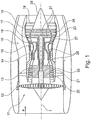
- the gas turbine engine 10 is an example of a turbomachine to which the invention may find application. However, it will be understood from the following that the invention can be used with other turbomachinery as well.
- the engine 10 is formed in a conventional manner and comprises in succession an air inlet 11, a fan circulating in a housing 12, a medium pressure compressor 13, a high pressure compressor 14, a combustion chamber 15, a high pressure turbine 16, a medium pressure turbine 17 and a Low-pressure turbine 18 and an exhaust nozzle 19, which are all arranged around a central engine axis 1.
- the intermediate-pressure compressor 13 and the high-pressure compressor 14 each comprise a plurality of stages, each of which has a circumferentially extending array of fixed stationary vanes 20, commonly referred to as stator vanes, extending radially inward from the engine casing 21 in an annular flow passage through the compressors 13, 14 protrude.
- the compressors further include an array of compressor blades 22 projecting radially outwardly from a rotatable drum or disc 26 coupled to hubs 27 of high pressure turbine 16 and mid pressure turbine 17, respectively.
- the turbine sections 16, 17, 18 have similar stages, comprising an array of fixed vanes 23 projecting radially inward from the housing 21 into the annular flow passage through the turbines 16, 17, 18, and a downstream array of turbine blades 24 projecting outwardly from a rotatable hub 27.
- the compressor drum or compressor disk 26 and the vanes 22 disposed thereon and the turbine rotor hub 27 and the turbine blades 24 disposed thereon rotate about the engine axis 1 during operation.
- the Fig. 2 shows a partial perspective view of a compressor with multiple rows of adjustable vanes 20, between each of which compressor blades 22 are arranged.
- the individual guide vanes 20 are each pivotable about a radial axis 44. They are connected to a lever 45, which is rotatably coupled at its opposite end portion with a Leitschaufelverstellring 29. By a rotation of the Leitschaufelverstellrings 29 in the circumferential direction is a pivoting of the individual lever 45. This causes a rotation of the vanes 20 about the respective axis 44 causes.
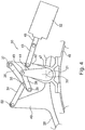
- FIGS. 3 to 5 show a first embodiment of the invention in a schematic side view.
- a rotatable about a stationary axis of rotation 33 crankshaft member 31 is mounted by means of a bearing block 47.
- This comprises a first cam element 41 and a second cam element 42.
- the second cam element is connected via an intermediate lever 43 with an actuator 32.
- This comprises an actuating element 48, which is longitudinally displaceable, as can be seen from the comparison of FIGS. 3 to 5 results. It is understood that the intermediate lever 43 is pivotally connected to the actuating element 48 and the second cam member 42.
- FIGS. 3 to 5 the Leitschaufelverstellring 29 which is displaceable in the circumferential direction, as in connection with FIG. 2 explains to adjust the vanes 20.
- a bearing lug 49 is attached, which is connected via a rotary joint 50 with a first lever 34.
- the opposite end of the first lever 34 is coupled by means of a hinge 35 with the middle part of a second lever 36.
- the second lever 36 is supported at its one end by means of a fixed pivot point 37 on the housing 46, while the other end of the second lever 36 is coupled by means of a hinge 38 with a third lever 39.
- the third lever 39 in turn is fixed at its other end by means of a hinge 40 to the first cam member 41.
- FIG. 6 shows a modified embodiment, which differs from the embodiment of the FIGS. 3 to 5 with respect to the position of the fixed pivot point 37. This is according to FIG. 6 arranged close to the housing 46, while the embodiment of the FIGS. 3 to 5 the pivot point 37 provides a radially outer region of the bearing block 47.
- FIG. 7 shows a simplified graphical representation, which illustrates the clearly non-constant transmission ratio according to the invention compared to the approximately constant transmission ratio according to the prior art.
- the angle of the crankshaft element is shown against the blade angle.
Description
Die Erfindung bezieht sich auf eine Leitschaufelverstellvorrichtung für einen Kompressor oder eine Turbine einer Gasturbine gemäß dem Oberbegriff des Anspruchs 1.The invention relates to a guide vane adjusting device for a compressor or a turbine of a gas turbine according to the preamble of
Im Einzelnen bezieht sich die Erfindung auf eine Leitschaufelverstellvorrichtung für einen Kompressor oder eine Turbine mit einer Vielzahl von jeweils um eine radiale Achse schwenkbaren Leitschaufeln, welche in zumindest zwei Radialebenen angeordnet sind. Die Leitschaufeln bilden somit jeweils eine zyklisch-symmetrische oder scheibenförmige Anordnung, wobei zwischen den zumindest zwei Leitschaufelanordnungen und/oder in Strömungsrichtung stromauf und stromab Laufschaufeln angeordnet sind, so wie dies aus dem Stand der Technik bekannt ist.More particularly, the invention relates to a vane adjusting device for a compressor or turbine having a plurality of vanes each pivotable about a radial axis arranged in at least two radial planes. The vanes thus each form a cyclic-symmetrical or disc-shaped arrangement, wherein between the at least two vane assemblies and / or in the flow direction upstream and downstream rotor blades are arranged, as is known from the prior art.
Zur Verstellung der Leitschaufeln jeder zyklisch-symmetrischen oder scheibenförmigen Anordnung von Leitschaufeln ist ein Leitschaufelverstellring vorgesehen, welcher in Umfangsrichtung verdrehbar ist. Der Leitschaufelverstellring ist mit der jeweiligen Leitschaufel über einen Hebelmechanismus gekoppelt, so dass bei einer Verdrehung des Leitschaufelverstellrings die Leitschaufeln um ihre radialen Achsen verschwenkt werden. Der Leitschaufelverstellring ist mit einer geeigneten Betätigungsvorrichtung gekoppelt.To adjust the vanes of each cyclic-symmetrical or disk-shaped arrangement of vanes, a Leitschaufelverstellring is provided, which is rotatable in the circumferential direction. The vane adjusting ring is coupled to the respective vane via a lever mechanism such that upon rotation of the vane adjusting ring, the vanes are pivoted about their radial axes. The vane adjusting ring is coupled to a suitable actuator.
Derartige Anordnungen sind beispielsweise aus der
Mittels der Betätigungsvorrichtung ist es somit möglich, den Anstellwinkel der jeweiligen Leitschaufel den Betriebsbedingungen des Kompressors oder der Turbine anzupassen. Dabei kann sich bei den aus dem Stand der Technik bekannten Vorrichtungen der Nachteil ergeben, dass, durch die annähernd lineare Verstellung bzw. Verstellung mit annähernd festem Übersetzungsverhältnis des Leitschaufelverstellrings und damit der Leitschaufeln keine optimale Verstellung oder Einstellung der Leitschaufeln möglich ist. So ist es insbesondere nur möglich, über einen Teil-Betriebsbereich die Schaufeln optimal einzustellen, während bei anderen Betriebsbedingungen der Gasturbine die Schaufeln nicht mit einem optimalen Winkel eingestellt werden können. Dies führt zu erhöhtem Brennstoffverbrauch und birgt die Gefahr von Strömungsablösungen an den Schaufelprofilen. Weiterhin ist es erforderlich, bei einem Kompressor Ablassventile (bleed valves) vorzusehen. Hierdurch erhöht sich der gesamte Fertigungsaufwand der Gasturbine. Weiterhin ergibt sich ein größeres Gesamtgewicht.By means of the actuating device, it is thus possible to adapt the angle of attack of the respective guide vane to the operating conditions of the compressor or of the turbine. It may result in the known from the prior art devices, the disadvantage that, by the approximately linear adjustment or adjustment with approximately fixed ratio of the Leitschaufelverstellrings and thus the vanes no optimal adjustment or adjustment of the vanes is possible. Thus, in particular, it is only possible to optimally adjust the blades over a partial operating range, while in other operating conditions of the gas turbine, the blades can not be adjusted with an optimum angle. this leads to Increased fuel consumption and carries the risk of flow separation on the blade profiles. Furthermore, it is necessary to provide discharge valves (bleed valves) in a compressor. This increases the overall production cost of the gas turbine. Furthermore, there is a greater total weight.
Es wurde im Stand der Technik versucht, diese Effekte konstruktiv dadurch zu lösen, dass insbesondere die Leitschaufelverstellringe sowie deren Lagerung komplexer ausgebildet wurden oder die Anzahl der aktiven Betätigungsmechanismen erhöht wurde. Hieraus ergeben sich jedoch zusätzliche Kosten, zusätzliches Gewicht sowie ein größerer Platzbedarf.It has been attempted in the prior art to solve these effects constructively in that in particular the Leitschaufelverstellringe and their storage were made more complex or the number of active operating mechanisms has been increased. This, however, additional costs, additional weight and a larger footprint.
Der Erfindung liegt die Aufgabe zugrunde, eine Leitschaufelverstellvorrichtung für einen Kompressor oder eine Turbine einer Gasturbine der eingangs genannten Art zu schaffen, welche bei einfachem Aufbau und einfacher, kostengünstiger Herstellbarkeit die Nachteile des Standes der Technik vermeidet und eine präzise Verstellung der Leitschaufeln ermöglicht.The invention has for its object to provide a Leitschaufelverstellvorrichtung for a compressor or a turbine of a gas turbine of the type mentioned, which avoids the disadvantages of the prior art with a simple structure and simple, cost-effective manufacturability and allows precise adjustment of the vanes.
Erfindungsgemäß wird die Aufgabe durch die Merkmalskombination des Anspruchs 1 gelöst, die Unteransprüche zeigen weitere vorteilhafte Ausgestaltungen der Erfindung.According to the invention the object is achieved by the combination of features of
Erfindungsgemäß ist somit vorgesehen, dass die Betätigungsvorrichtung ein Kurbelwellenelement umfasst, welches mittels eines Aktuators um eine ortsfeste Drehachse verschwenkbar ist. Das Kurbelwellenelement umfasst bevorzugterweise ein erstes und ein zweites Nockenelement, so wie dies bei üblichen Kurbelwellen vorgesehen ist. Bevorzugterweise ist das Kurbelwellenelement mit seiner Drehachse parallel zur Triebwerksachse und damit senkrecht zur Drehachse der Schaufeln angeordnet.According to the invention it is thus provided that the actuating device comprises a crankshaft element, which is pivotable about an axis of rotation by means of an actuator. The crankshaft element preferably comprises a first and a second cam element, as provided in conventional crankshafts. Preferably, the crankshaft element is arranged with its axis of rotation parallel to the engine axis and thus perpendicular to the axis of rotation of the blades.
Die Betätigung des Kurbelwellenelements erfolgt erfindungsgemäß mittels eines Aktuators. Dieser kann als hydraulische Kolben-Zylindereinheit ausgebildet sein, es ist jedoch auch möglich, diesen als elektrischen Servoantrieb auszugestalten.The actuation of the crankshaft element takes place according to the invention by means of an actuator. This can be designed as a hydraulic piston-cylinder unit, but it is also possible to design this as an electric servo drive.
Die erfindungsgemäße Leitschaufelverstellvorrichtung umfasst zur Ausbildung eines Getriebes mit ausgeprägt nicht-konstanten Übersetzungsverhältnis drei Hebel, nämlich einen ersten Hebel, einen zweiten Hebel und einen dritten Hebel. Der erste Hebel ist gelenkig an dem Leitschaufelverstellring angelenkt, sein anderes, freies Ende ist gelenkig mit einem mittleren Bereich des zweiten Hebels verbunden. Der zweite Hebel ist an seinem einen Ende an einem ortsfesten Drehpunkt gelagert und an seinem anderen Ende gelenkig mit dem dritten Hebel gekoppelt. Dieser dritte Hebel wiederum ist mit seinem anderen, freien Ende gelenkig an dem Kurbelwellenelement gelagert. Durch eine Verdrehung des Kurbelwellenelements werden somit der erste und der dritte Hebel durch Zwischenschaltung des zweiten Hebels bewegt. Bei geeigneter Dimensionierung ergibt sich somit eine Bewegung (Verdrehung) des Leitschaufelverstellrings in Umfangsrichtung mit nicht-konstantem Übersetzungsverhältnis. Es erfolgt somit eine Umsetzung einer linearen, gleichmäßigen Bewegung des Aktuators in eine nicht-lineare Verstellung des Leitschaufelverstellrings und damit auch in eine nicht-lineare Einstellung der Schaufeln. Hierdurch ist es möglich, einen optimalen Anstellwinkel der Schaufeln für jede Drehzahl der Gasturbine zu realisieren.The Leitschaufelverstellvorrichtung invention comprises to form a transmission with a pronounced non-constant gear ratio three levers, namely a first lever, a second lever and a third lever. The first lever is articulated to the Leitschaufelverstellring, its other, free end is pivotally connected to a central region of the second lever. The second lever is mounted at its one end to a fixed pivot point and coupled at its other end hinged to the third lever. This third lever in turn is articulated to the crankshaft member with its other, free end. By a rotation of the crankshaft element thus the first and the third lever are moved by interposition of the second lever. With suitable dimensioning thus results in a movement (rotation) of the Leitschaufelverstellrings in the circumferential direction with non-constant gear ratio. There is thus an implementation of a linear, uniform movement of the actuator in a non-linear adjustment of the Leitschaufelverstellrings and thus in a non-linear adjustment of the blades. This makes it possible to realize an optimum angle of attack of the blades for each speed of the gas turbine.
Die ortsfesten Drehpunkte können in geeigneter Weise im Hinblick auf das gewünschte nicht-konstante Übersetzungsverhältnis des durch die drei Hebel gebildeten Getriebes ausgewählt und den jeweiligen konstruktiven Bedingungen angepasst werden.The fixed pivot points can be selected in a suitable manner with regard to the desired non-constant transmission ratio of the transmission formed by the three levers and adapted to the respective design conditions.
Durch die erfindungsgemäße Ausgestaltung ergibt sich für alle Betriebsbedingungen der Gasturbine ein optimaler Anstellwinkel der Leitschaufeln. Dies führt zu einer verbesserten Verbrennung sowie verbesserten Strömungsbedingungen und einer besseren Bedienbarkeit der Gasturbine. Weiterhin ergeben sich wegen der geringeren Anzahl der benötigten Bauteile und der einfacheren Ausgestaltung der Bauteile geringere Kosten. Gegebenenfalls kann auf die aus dem Stand der Technik bekannten Auslassventile (bleed valves) verzichtet werden.The embodiment according to the invention results in an optimum angle of attack of the guide vanes for all operating conditions of the gas turbine. This leads to improved combustion and improved flow conditions and better operability of the gas turbine. Furthermore, due to the smaller number of components required and the simpler design of the components lower costs. Optionally, the known from the prior art exhaust valves (bleed valves) can be omitted.
Wie bereits erwähnt, ist es möglich, insbesondere den ortsfesten Drehpunkt, um den sich der zweite Hebel dreht, konstruktiv optimiert anzuordnen, beispielsweise radial innenliegend oder radial außenliegend (bezogen auf die Maschinenachse) zu dem Kurbelwellenelement.As already mentioned, it is possible, in particular the fixed pivot point about which the second lever rotates, to arrange structurally optimized, for example radially inward or radially outboard (relative to the machine axis) to the crankshaft element.
In besonders günstiger Ausgestaltung ist vorgesehen, dass der Aktuator über einen Zwischenhebel mit dem Kurbelwellenelement verbunden ist. Somit ist es möglich, den Aktuator an einem günstigen Einbauort vorzusehen und eine optimierte Krafteinleitung von dem Aktuator auf das Nockenelement zu gewährleisten.In a particularly favorable embodiment, it is provided that the actuator is connected via an intermediate lever with the crankshaft element. Thus, it is possible to provide the actuator at a favorable installation location and to ensure an optimized introduction of force from the actuator to the cam member.
Erfindungsgemäß ist es weiterhin möglich, mehrere Leitschaufelringe mit der erfindungsgemäßen Vorrichtung unter Verwendung eines gemeinsamen Kurbelwellenelements und eines Aktuators zu verstellen.According to the invention, it is also possible to adjust a plurality of guide vane rings with the device according to the invention using a common crankshaft element and an actuator.
Im Folgenden wird die Erfindung anhand von Ausführungsbeispielen in Verbindung mit der Zeichnung beschrieben. Dabei zeigt:
- Fig. 1
- eine schematische Darstellung eines Gasturbinentriebwerks gemäß der vorliegenden Erfindung;
- Fig. 2
- eine perspektivische Teilansicht eines Kompressors mit verstellbaren Leitschaufeln und Leitschaufelverstellringen;
- Fig. 3 - 5
- unterschiedliche Betriebszustände eines ersten Ausführungsbeispiels der Erfindung in vereinfachter Darstellung;
- Fig. 6
- eine schematische Ansicht, ähnlich den
Figuren 3 bis 5 , eines weiteren Ausführungsbeispiels der Erfindung, und - Fig. 7
- eine graphische Darstellung der Verdeutlichung des nicht-konstanten Übersetzungsverhältnisses der Verstellung gemäß der Erfindung.
- Fig. 1
- a schematic representation of a gas turbine engine according to the present invention;
- Fig. 2
- a partial perspective view of a compressor with adjustable vanes and Leitschaufelverstellringen;
- Fig. 3-5
- different operating states of a first embodiment of the invention in a simplified representation;
- Fig. 6
- a schematic view similar to the
FIGS. 3 to 5 , Another embodiment of the invention, and - Fig. 7
- a graphical representation of the clarification of the non-constant transmission ratio of the adjustment according to the invention.
Das Gasturbinentriebwerk 10 gemäß
Der Mitteldruckkompressor 13 und der Hochdruckkompressor 14 umfassen jeweils mehrere Stufen, von denen jede eine in Umfangsrichtung verlaufende Anordnung fester stationärer Leitschaufeln 20 aufweist, die allgemein als Statorschaufeln bezeichnet werden und die radial nach innen vom Triebwerksgehäuse 21 in einem ringförmigen Strömungskanal durch die Kompressoren 13, 14 vorstehen. Die Kompressoren weisen weiter eine Anordnung von Kompressorlaufschaufeln 22 auf, die radial nach außen von einer drehbaren Trommel oder Scheibe 26 vorstehen, die mit Naben 27 der Hochdruckturbine 16 bzw. der Mitteldruckturbine 17 gekoppelt sind.The intermediate-
Die Turbinenabschnitte 16, 17, 18 weisen ähnliche Stufen auf, umfassend eine Anordnung von festen Leitschaufeln 23, die radial nach innen vom Gehäuse 21 in den ringförmigen Strömungskanal durch die Turbinen 16, 17, 18 vorstehen, und eine nachfolgende Anordnung von Turbinenschaufeln 24, die nach außen von einer drehbaren Nabe 27 vorstehen. Die Kompressortrommel oder Kompressorscheibe 26 und die darauf angeordneten Schaufeln 22 sowie die Turbinenrotornabe 27 und die darauf angeordneten Turbinenlaufschaufeln 24 drehen sich im Betrieb um die Triebwerksachse 1.The
Die Erfindung wird nachfolgend anhand eines Kompressors beschrieben, sie ist jedoch auch für Leitschaufeln einer Turbine anwendbar.The invention will be described below with reference to a compressor, but it is also applicable to vanes of a turbine.
Die
Die
Das zweite Nockenelement ist über einen Zwischenhebel 43 mit einem Aktuator 32 verbunden. Dieser umfasst ein Betätigungselement 48, welches längsverschiebbar ist, sowie sich dies aus dem Vergleich der
Weiterhin zeigen die
Durch eine Verschiebung des Betätigungselements 48 (vgl. die
Die
Ansonsten sind bei den Ausführungsbeispielen der
Die
- 11
- TriebwerksachseEngine axis
- 1010
- GasturbinentriebwerkGas turbine engine
- 1111
- Lufteinlassair intake
- 1212
- im Gehäuse umlaufender Fanin the housing revolving fan
- 1313
- MitteldruckkompressorMedium pressure compressor
- 1414
- HochdruckkompressorHigh pressure compressor
- 1515
- Brennkammercombustion chamber
- 1616
- HochdruckturbineHigh-pressure turbine
- 1717
- MitteldruckturbineIntermediate pressure turbine
- 1818
- NiederdruckturbineLow-pressure turbine
- 1919
- Abgasdüseexhaust nozzle
- 2020
- Verdichterleitschaufelncompressor guide
- 2121
- TriebwerksgehäuseEngine casing
- 2222
- KompressorlaufschaufelnCompressor blades
- 2323
- Turbinenleitschaufelnturbine
- 2424
- Turbinenschaufelnturbine blades
- 2626
- Kompressortrommel oder -scheibeCompressor drum or disc
- 2727
- TurbinenrotornabeTurbinenrotornabe
- 2828
- Auslaufkonusoutlet cone
- 2929
- LeitschaufelverstellringLeitschaufelverstellring
- 3030
- Betätigungsvorrichtungactuator
- 3131
- Kurbelwellenelementcrank element
- 3232
- Aktuatoractuator
- 3333
- ortsfeste Drehachsefixed axis of rotation
- 3434
- erster Hebelfirst lever
- 3535
- Gelenkjoint
- 3636
- zweiter Hebelsecond lever
- 3737
- ortsfester Drehpunktfixed fulcrum
- 3838
- Gelenkjoint
- 3939
- dritter Hebelthird lever
- 4040
- Gelenkjoint
- 4141
- erstes Nockenelementfirst cam element
- 4242
- zweites Nockenelementsecond cam element
- 4343
- Zwischenhebelintermediate lever
- 4444
- Achseaxis
- 4545
- Hebellever
- 4646
- Gehäusecasing
- 4747
- Lagerbockbearing block
- 4848
- Betätigungselementjig
- 4949
- Lageransatzbearing projection
- 5050
- Gelenkjoint
Claims (8)
- Stator vane adjusting device of a gas turbine having a plurality of stator vanes (20) each swivellable about a radial axis (44) and arranged in at least two radial planes, as well as at least one stator vane adjusting ring (29) coupled to the respective stator vanes (20) and rotatable in the circumferential direction by at least one actuating device (30), with the actuating device (30) including a crankshaft element (31) swivellable about a stationary pivot axis (33) by means of an actuator (32), and the stator vane adjusting device featuring a first, a second and a third lever, characterized in that the first lever (34) is articulated by a joint to the stator vane adjusting ring (29), with its free end being connected by a joint (35) to a center area of the second lever (36), with the second lever (36) being mounted at its one end on a stationary pivot point (37) and at its other end being linked by a joint (38) to the third lever (39), which is mounted by a joint (40) at its free end on the crankshaft element (31).
- Device in accordance with Claim 1, characterized in that the stationary pivot point (37) of the second lever (36) is arranged radially inside the crankshaft element (31) relative to the engine axis (1) of the gas turbine.
- Device in accordance with Claim 1, characterized in that the stationary pivot point (37) of the second lever (36) is arranged radially outside the crankshaft element (31) relative to the engine axis (1) of the gas turbine.
- Device in accordance with one of the Claims 1 to 3, characterized in that the crankshaft element (31) includes at least a first (41) and a second (42) cam element, with the third lever (39) being articulated to the first cam element (41) and the actuator (32) being coupled to the second cam element (42).
- Device in accordance with one of the Claims 1 to 4, characterized in that the actuator (32) is connected to the crankshaft element (31) via an intermediate lever (43).
- Device in accordance with one of the Claims 1 to 5, characterized in that several stator vane adjusting rings (29) are provided which are each coupled to the crankshaft element (31) by means of a first (34), a second (36) and a third (39) lever.
- Device in accordance with one of the Claims 1 to 6, characterized in that the latter is designed for converting a linear movement of the actuator (32) into a non-linear rotation of the stator vane adjusting ring (29).
- Device in accordance with one of the Claims 1 to 7, characterized in that the lengths of the first (34), the second (36) and the third (39) lever are selected such that a gear with a distinctly non-constant transmission ratio is provided.
Applications Claiming Priority (1)
| Application Number | Priority Date | Filing Date | Title |
|---|---|---|---|
| DE102012021876.1A DE102012021876A1 (en) | 2012-11-07 | 2012-11-07 | Guide vane adjusting a gas turbine |
Publications (3)
| Publication Number | Publication Date |
|---|---|
| EP2730751A2 EP2730751A2 (en) | 2014-05-14 |
| EP2730751A3 EP2730751A3 (en) | 2017-07-19 |
| EP2730751B1 true EP2730751B1 (en) | 2018-01-31 |
Family
ID=49554056
Family Applications (1)
| Application Number | Title | Priority Date | Filing Date |
|---|---|---|---|
| EP13191938.3A Not-in-force EP2730751B1 (en) | 2012-11-07 | 2013-11-07 | Vane adjustment device for a gas turbine |
Country Status (3)
| Country | Link |
|---|---|
| US (1) | US9453426B2 (en) |
| EP (1) | EP2730751B1 (en) |
| DE (1) | DE102012021876A1 (en) |
Families Citing this family (4)
| Publication number | Priority date | Publication date | Assignee | Title |
|---|---|---|---|---|
| DE102015004648A1 (en) * | 2015-04-15 | 2016-10-20 | Man Diesel & Turbo Se | Guide vane adjusting device and turbomachine |
| US11401825B2 (en) | 2018-10-29 | 2022-08-02 | Rolls-Royce Deutschland Ltd & Co Kg | Gas turbine engine control system and method for limiting turbine overspeed in case of a shaft failure |
| DE102018126930B4 (en) | 2018-10-29 | 2023-05-17 | Rolls-Royce Deutschland Ltd & Co Kg | Adjusting device and method for adjusting the guide vanes of a compressor of a gas turbine engine |
| CN114991881B (en) * | 2021-03-01 | 2023-09-19 | 中国航发商用航空发动机有限责任公司 | Stationary blade adjusting mechanism and engine comprising same |
Family Cites Families (9)
| Publication number | Priority date | Publication date | Assignee | Title |
|---|---|---|---|---|
| GB1211447A (en) * | 1968-09-17 | 1970-11-04 | Leyland Gas Turbines Ltd | Turbine having variable angle nozzle guide vanes |
| DE2041109C3 (en) | 1970-08-19 | 1975-10-02 | Motoren- Und Turbinen-Union Muenchen Gmbh, 8000 Muenchen | Guide vane adjustment device for the guide vane ring of the power turbine of a twin-shaft gas turbine, in particular for driving a motor vehicle |
| US3861822A (en) * | 1974-02-27 | 1975-01-21 | Gen Electric | Duct with vanes having selectively variable pitch |
| US4720237A (en) * | 1986-02-24 | 1988-01-19 | United Technologies Corporation | Unison ring actuator assembly |
| FR2739137B1 (en) | 1995-09-27 | 1997-10-31 | Snecma | DEVICE FOR CONTROLLING A VARIABLE SETTING BLADE STAGE |
| FR2856424B1 (en) | 2003-06-20 | 2005-09-23 | Snecma Moteurs | DEVICE FOR VARIABLE SETTING OF TWO FLOORS OF BLADES FIXED ON A TURBOJETACTOR |
| FR2885969B1 (en) | 2005-05-17 | 2007-08-10 | Snecma Moteurs Sa | TURBOMACHINE VARIABLE ROTATION ANGLE STATOR AUTONER STAGE CONTROL SYSTEM |
| FR2936565B1 (en) * | 2008-09-30 | 2015-07-24 | Snecma | SYSTEM FOR CONTROLLING EQUIPMENT WITH VARIABLE GEOMETRY OF A TURBOMACHINE IN PARTICULAR BY ARTICULATED GUIGNOLS. |
| DE102012007129A1 (en) * | 2012-04-10 | 2013-10-10 | Rolls-Royce Deutschland Ltd & Co Kg | Guide vane adjusting a gas turbine |
-
2012
- 2012-11-07 DE DE102012021876.1A patent/DE102012021876A1/en not_active Withdrawn
-
2013
- 2013-11-06 US US14/073,157 patent/US9453426B2/en active Active
- 2013-11-07 EP EP13191938.3A patent/EP2730751B1/en not_active Not-in-force
Non-Patent Citations (1)
| Title |
|---|
| None * |
Also Published As
| Publication number | Publication date |
|---|---|
| EP2730751A3 (en) | 2017-07-19 |
| US20140127003A1 (en) | 2014-05-08 |
| DE102012021876A1 (en) | 2014-05-22 |
| EP2730751A2 (en) | 2014-05-14 |
| US9453426B2 (en) | 2016-09-27 |
Similar Documents
| Publication | Publication Date | Title |
|---|---|---|
| EP2650490B1 (en) | Turbine vane adjustment device for a gas turbine | |
| EP3000984B1 (en) | Turbine vane adjustment device for a gas turbine | |
| EP3283733B1 (en) | Variable guide vane actuating device and turbomachine | |
| EP2845999B1 (en) | Method for balancing and for mounting a turbine rotor | |
| EP2617947B1 (en) | Aircraft gas turbine engine with adjustable fan | |
| DE102014104318A1 (en) | Flow manipulation assembly for a turbine exhaust diffuser | |
| EP2628936A2 (en) | Aviation gas turbine thrust reversing device | |
| EP2730751B1 (en) | Vane adjustment device for a gas turbine | |
| DE102018221812A1 (en) | Exhaust gas turbine with an exhaust gas guide device for an exhaust gas turbocharger and exhaust gas turbocharger | |
| EP3269941B1 (en) | Adjustable cascade for turbomachine | |
| EP2831379B1 (en) | Holder ring | |
| EP3176386A1 (en) | Inner shroud assembly, corresponding intermediate shroud, inner casing and turbomachine | |
| EP1746256A1 (en) | Reduction of gap loss in turbomachines | |
| DE102011008918A1 (en) | Aircraft gas turbine thrust reverser, has detour elements arranged at peripheral region of cowl, and lever swingably arranged at rear end region of detour elements, where lever enables pivoting doors with displacement of detour elements | |
| DE102008060251B4 (en) | Exhaust gas turbocharger with variable turbine geometry | |
| DE102008033560A1 (en) | Gas turbine engine with adjustable vanes | |
| DE102015206985A1 (en) | Engine cowling of an aircraft gas turbine | |
| EP1391585B1 (en) | Turbocharger with variable geometry | |
| DE102015014889A1 (en) | Compressor, in particular radial compressor, for an exhaust gas turbocharger of an internal combustion engine | |
| WO2017097665A1 (en) | Aircraft gas turbine having a variable outlet nozzle of a bypass flow channel | |
| DE102011101197B4 (en) | Aircraft gas turbine with hydraulic or pneumatic auxiliary unit drive | |
| EP2261466A1 (en) | Adjustment device for stator vanes of a turbine | |
| EP1803903A1 (en) | Actuator for the rotation of adjustable blades of a turbine | |
| DE102011102359B4 (en) | Air turbine with adjustable fan | |
| WO2018162306A1 (en) | Turbine comprising adjustable guide vanes |
Legal Events
| Date | Code | Title | Description |
|---|---|---|---|
| PUAI | Public reference made under article 153(3) epc to a published international application that has entered the european phase |
Free format text: ORIGINAL CODE: 0009012 |
|
| 17P | Request for examination filed |
Effective date: 20131107 |
|
| AK | Designated contracting states |
Kind code of ref document: A2 Designated state(s): AL AT BE BG CH CY CZ DE DK EE ES FI FR GB GR HR HU IE IS IT LI LT LU LV MC MK MT NL NO PL PT RO RS SE SI SK SM TR |
|
| AX | Request for extension of the european patent |
Extension state: BA ME |
|
| PUAL | Search report despatched |
Free format text: ORIGINAL CODE: 0009013 |
|
| RIC1 | Information provided on ipc code assigned before grant |
Ipc: F02C 9/20 20060101ALI20170530BHEP Ipc: F01D 17/16 20060101AFI20170530BHEP |
|
| AK | Designated contracting states |
Kind code of ref document: A3 Designated state(s): AL AT BE BG CH CY CZ DE DK EE ES FI FR GB GR HR HU IE IS IT LI LT LU LV MC MK MT NL NO PL PT RO RS SE SI SK SM TR |
|
| AX | Request for extension of the european patent |
Extension state: BA ME |
|
| RIC1 | Information provided on ipc code assigned before grant |
Ipc: F01D 17/16 20060101AFI20170612BHEP Ipc: F02C 9/20 20060101ALI20170612BHEP |
|
| R17P | Request for examination filed (corrected) |
Effective date: 20170802 |
|
| RBV | Designated contracting states (corrected) |
Designated state(s): AL AT BE BG CH CY CZ DE DK EE ES FI FR GB GR HR HU IE IS IT LI LT LU LV MC MK MT NL NO PL PT RO RS SE SI SK SM TR |
|
| GRAP | Despatch of communication of intention to grant a patent |
Free format text: ORIGINAL CODE: EPIDOSNIGR1 |
|
| INTG | Intention to grant announced |
Effective date: 20170926 |
|
| GRAS | Grant fee paid |
Free format text: ORIGINAL CODE: EPIDOSNIGR3 |
|
| GRAA | (expected) grant |
Free format text: ORIGINAL CODE: 0009210 |
|
| RIN1 | Information on inventor provided before grant (corrected) |
Inventor name: KLAUKE, DR.-ING. THOMAS Inventor name: MOJEM, MATS Inventor name: RAJARATNAM, NISHANTH |
|
| AK | Designated contracting states |
Kind code of ref document: B1 Designated state(s): AL AT BE BG CH CY CZ DE DK EE ES FI FR GB GR HR HU IE IS IT LI LT LU LV MC MK MT NL NO PL PT RO RS SE SI SK SM TR |
|
| REG | Reference to a national code |
Ref country code: GB Ref legal event code: FG4D Free format text: NOT ENGLISH Ref country code: CH Ref legal event code: EP |
|
| REG | Reference to a national code |
Ref country code: AT Ref legal event code: REF Ref document number: 967597 Country of ref document: AT Kind code of ref document: T Effective date: 20180215 |
|
| REG | Reference to a national code |
Ref country code: IE Ref legal event code: FG4D Free format text: LANGUAGE OF EP DOCUMENT: GERMAN |
|
| REG | Reference to a national code |
Ref country code: DE Ref legal event code: R096 Ref document number: 502013009321 Country of ref document: DE |
|
| REG | Reference to a national code |
Ref country code: NL Ref legal event code: MP Effective date: 20180131 |
|
| REG | Reference to a national code |
Ref country code: LT Ref legal event code: MG4D |
|
| PG25 | Lapsed in a contracting state [announced via postgrant information from national office to epo] |
Ref country code: FI Free format text: LAPSE BECAUSE OF FAILURE TO SUBMIT A TRANSLATION OF THE DESCRIPTION OR TO PAY THE FEE WITHIN THE PRESCRIBED TIME-LIMIT Effective date: 20180131 Ref country code: NO Free format text: LAPSE BECAUSE OF FAILURE TO SUBMIT A TRANSLATION OF THE DESCRIPTION OR TO PAY THE FEE WITHIN THE PRESCRIBED TIME-LIMIT Effective date: 20180430 Ref country code: LT Free format text: LAPSE BECAUSE OF FAILURE TO SUBMIT A TRANSLATION OF THE DESCRIPTION OR TO PAY THE FEE WITHIN THE PRESCRIBED TIME-LIMIT Effective date: 20180131 Ref country code: HR Free format text: LAPSE BECAUSE OF FAILURE TO SUBMIT A TRANSLATION OF THE DESCRIPTION OR TO PAY THE FEE WITHIN THE PRESCRIBED TIME-LIMIT Effective date: 20180131 Ref country code: NL Free format text: LAPSE BECAUSE OF FAILURE TO SUBMIT A TRANSLATION OF THE DESCRIPTION OR TO PAY THE FEE WITHIN THE PRESCRIBED TIME-LIMIT Effective date: 20180131 Ref country code: ES Free format text: LAPSE BECAUSE OF FAILURE TO SUBMIT A TRANSLATION OF THE DESCRIPTION OR TO PAY THE FEE WITHIN THE PRESCRIBED TIME-LIMIT Effective date: 20180131 |
|
| PG25 | Lapsed in a contracting state [announced via postgrant information from national office to epo] |
Ref country code: GR Free format text: LAPSE BECAUSE OF FAILURE TO SUBMIT A TRANSLATION OF THE DESCRIPTION OR TO PAY THE FEE WITHIN THE PRESCRIBED TIME-LIMIT Effective date: 20180501 Ref country code: IS Free format text: LAPSE BECAUSE OF FAILURE TO SUBMIT A TRANSLATION OF THE DESCRIPTION OR TO PAY THE FEE WITHIN THE PRESCRIBED TIME-LIMIT Effective date: 20180531 Ref country code: LV Free format text: LAPSE BECAUSE OF FAILURE TO SUBMIT A TRANSLATION OF THE DESCRIPTION OR TO PAY THE FEE WITHIN THE PRESCRIBED TIME-LIMIT Effective date: 20180131 Ref country code: SE Free format text: LAPSE BECAUSE OF FAILURE TO SUBMIT A TRANSLATION OF THE DESCRIPTION OR TO PAY THE FEE WITHIN THE PRESCRIBED TIME-LIMIT Effective date: 20180131 Ref country code: BG Free format text: LAPSE BECAUSE OF FAILURE TO SUBMIT A TRANSLATION OF THE DESCRIPTION OR TO PAY THE FEE WITHIN THE PRESCRIBED TIME-LIMIT Effective date: 20180430 Ref country code: PL Free format text: LAPSE BECAUSE OF FAILURE TO SUBMIT A TRANSLATION OF THE DESCRIPTION OR TO PAY THE FEE WITHIN THE PRESCRIBED TIME-LIMIT Effective date: 20180131 Ref country code: RS Free format text: LAPSE BECAUSE OF FAILURE TO SUBMIT A TRANSLATION OF THE DESCRIPTION OR TO PAY THE FEE WITHIN THE PRESCRIBED TIME-LIMIT Effective date: 20180131 |
|
| PG25 | Lapsed in a contracting state [announced via postgrant information from national office to epo] |
Ref country code: MT Free format text: LAPSE BECAUSE OF FAILURE TO SUBMIT A TRANSLATION OF THE DESCRIPTION OR TO PAY THE FEE WITHIN THE PRESCRIBED TIME-LIMIT Effective date: 20180131 |
|
| PG25 | Lapsed in a contracting state [announced via postgrant information from national office to epo] |
Ref country code: EE Free format text: LAPSE BECAUSE OF FAILURE TO SUBMIT A TRANSLATION OF THE DESCRIPTION OR TO PAY THE FEE WITHIN THE PRESCRIBED TIME-LIMIT Effective date: 20180131 Ref country code: AL Free format text: LAPSE BECAUSE OF FAILURE TO SUBMIT A TRANSLATION OF THE DESCRIPTION OR TO PAY THE FEE WITHIN THE PRESCRIBED TIME-LIMIT Effective date: 20180131 Ref country code: RO Free format text: LAPSE BECAUSE OF FAILURE TO SUBMIT A TRANSLATION OF THE DESCRIPTION OR TO PAY THE FEE WITHIN THE PRESCRIBED TIME-LIMIT Effective date: 20180131 Ref country code: IT Free format text: LAPSE BECAUSE OF FAILURE TO SUBMIT A TRANSLATION OF THE DESCRIPTION OR TO PAY THE FEE WITHIN THE PRESCRIBED TIME-LIMIT Effective date: 20180131 |
|
| REG | Reference to a national code |
Ref country code: DE Ref legal event code: R097 Ref document number: 502013009321 Country of ref document: DE |
|
| PG25 | Lapsed in a contracting state [announced via postgrant information from national office to epo] |
Ref country code: CZ Free format text: LAPSE BECAUSE OF FAILURE TO SUBMIT A TRANSLATION OF THE DESCRIPTION OR TO PAY THE FEE WITHIN THE PRESCRIBED TIME-LIMIT Effective date: 20180131 Ref country code: SM Free format text: LAPSE BECAUSE OF FAILURE TO SUBMIT A TRANSLATION OF THE DESCRIPTION OR TO PAY THE FEE WITHIN THE PRESCRIBED TIME-LIMIT Effective date: 20180131 Ref country code: SK Free format text: LAPSE BECAUSE OF FAILURE TO SUBMIT A TRANSLATION OF THE DESCRIPTION OR TO PAY THE FEE WITHIN THE PRESCRIBED TIME-LIMIT Effective date: 20180131 Ref country code: DK Free format text: LAPSE BECAUSE OF FAILURE TO SUBMIT A TRANSLATION OF THE DESCRIPTION OR TO PAY THE FEE WITHIN THE PRESCRIBED TIME-LIMIT Effective date: 20180131 |
|
| PLBE | No opposition filed within time limit |
Free format text: ORIGINAL CODE: 0009261 |
|
| STAA | Information on the status of an ep patent application or granted ep patent |
Free format text: STATUS: NO OPPOSITION FILED WITHIN TIME LIMIT |
|
| 26N | No opposition filed |
Effective date: 20181102 |
|
| PG25 | Lapsed in a contracting state [announced via postgrant information from national office to epo] |
Ref country code: SI Free format text: LAPSE BECAUSE OF FAILURE TO SUBMIT A TRANSLATION OF THE DESCRIPTION OR TO PAY THE FEE WITHIN THE PRESCRIBED TIME-LIMIT Effective date: 20180131 |
|
| REG | Reference to a national code |
Ref country code: CH Ref legal event code: PL |
|
| PG25 | Lapsed in a contracting state [announced via postgrant information from national office to epo] |
Ref country code: MC Free format text: LAPSE BECAUSE OF FAILURE TO SUBMIT A TRANSLATION OF THE DESCRIPTION OR TO PAY THE FEE WITHIN THE PRESCRIBED TIME-LIMIT Effective date: 20180131 Ref country code: LU Free format text: LAPSE BECAUSE OF NON-PAYMENT OF DUE FEES Effective date: 20181107 |
|
| REG | Reference to a national code |
Ref country code: BE Ref legal event code: MM Effective date: 20181130 |
|
| REG | Reference to a national code |
Ref country code: IE Ref legal event code: MM4A |
|
| PG25 | Lapsed in a contracting state [announced via postgrant information from national office to epo] |
Ref country code: CH Free format text: LAPSE BECAUSE OF NON-PAYMENT OF DUE FEES Effective date: 20181130 Ref country code: LI Free format text: LAPSE BECAUSE OF NON-PAYMENT OF DUE FEES Effective date: 20181130 |
|
| PG25 | Lapsed in a contracting state [announced via postgrant information from national office to epo] |
Ref country code: IE Free format text: LAPSE BECAUSE OF NON-PAYMENT OF DUE FEES Effective date: 20181107 |
|
| PG25 | Lapsed in a contracting state [announced via postgrant information from national office to epo] |
Ref country code: BE Free format text: LAPSE BECAUSE OF NON-PAYMENT OF DUE FEES Effective date: 20181130 |
|
| REG | Reference to a national code |
Ref country code: AT Ref legal event code: MM01 Ref document number: 967597 Country of ref document: AT Kind code of ref document: T Effective date: 20181107 |
|
| PG25 | Lapsed in a contracting state [announced via postgrant information from national office to epo] |
Ref country code: AT Free format text: LAPSE BECAUSE OF NON-PAYMENT OF DUE FEES Effective date: 20181107 |
|
| PGFP | Annual fee paid to national office [announced via postgrant information from national office to epo] |
Ref country code: DE Payment date: 20191127 Year of fee payment: 7 |
|
| PGFP | Annual fee paid to national office [announced via postgrant information from national office to epo] |
Ref country code: FR Payment date: 20191125 Year of fee payment: 7 |
|
| PG25 | Lapsed in a contracting state [announced via postgrant information from national office to epo] |
Ref country code: TR Free format text: LAPSE BECAUSE OF FAILURE TO SUBMIT A TRANSLATION OF THE DESCRIPTION OR TO PAY THE FEE WITHIN THE PRESCRIBED TIME-LIMIT Effective date: 20180131 |
|
| PGFP | Annual fee paid to national office [announced via postgrant information from national office to epo] |
Ref country code: GB Payment date: 20191127 Year of fee payment: 7 |
|
| PG25 | Lapsed in a contracting state [announced via postgrant information from national office to epo] |
Ref country code: PT Free format text: LAPSE BECAUSE OF FAILURE TO SUBMIT A TRANSLATION OF THE DESCRIPTION OR TO PAY THE FEE WITHIN THE PRESCRIBED TIME-LIMIT Effective date: 20180131 |
|
| PG25 | Lapsed in a contracting state [announced via postgrant information from national office to epo] |
Ref country code: CY Free format text: LAPSE BECAUSE OF FAILURE TO SUBMIT A TRANSLATION OF THE DESCRIPTION OR TO PAY THE FEE WITHIN THE PRESCRIBED TIME-LIMIT Effective date: 20180131 Ref country code: MK Free format text: LAPSE BECAUSE OF NON-PAYMENT OF DUE FEES Effective date: 20180131 Ref country code: HU Free format text: LAPSE BECAUSE OF FAILURE TO SUBMIT A TRANSLATION OF THE DESCRIPTION OR TO PAY THE FEE WITHIN THE PRESCRIBED TIME-LIMIT; INVALID AB INITIO Effective date: 20131107 |
|
| REG | Reference to a national code |
Ref country code: DE Ref legal event code: R119 Ref document number: 502013009321 Country of ref document: DE |
|
| GBPC | Gb: european patent ceased through non-payment of renewal fee |
Effective date: 20201107 |
|
| PG25 | Lapsed in a contracting state [announced via postgrant information from national office to epo] |
Ref country code: FR Free format text: LAPSE BECAUSE OF NON-PAYMENT OF DUE FEES Effective date: 20201130 |
|
| PG25 | Lapsed in a contracting state [announced via postgrant information from national office to epo] |
Ref country code: DE Free format text: LAPSE BECAUSE OF NON-PAYMENT OF DUE FEES Effective date: 20210601 Ref country code: GB Free format text: LAPSE BECAUSE OF NON-PAYMENT OF DUE FEES Effective date: 20201107 |