EP1803861A1 - Profile for concrete structure and use of said profile - Google Patents
Profile for concrete structure and use of said profile Download PDFInfo
- Publication number
- EP1803861A1 EP1803861A1 EP05028689A EP05028689A EP1803861A1 EP 1803861 A1 EP1803861 A1 EP 1803861A1 EP 05028689 A EP05028689 A EP 05028689A EP 05028689 A EP05028689 A EP 05028689A EP 1803861 A1 EP1803861 A1 EP 1803861A1
- Authority
- EP
- European Patent Office
- Prior art keywords
- profile according
- profile
- base
- segments
- concrete
- Prior art date
- Legal status (The legal status is an assumption and is not a legal conclusion. Google has not performed a legal analysis and makes no representation as to the accuracy of the status listed.)
- Granted
Links
Images









Classifications
-
- E—FIXED CONSTRUCTIONS
- E04—BUILDING
- E04B—GENERAL BUILDING CONSTRUCTIONS; WALLS, e.g. PARTITIONS; ROOFS; FLOORS; CEILINGS; INSULATION OR OTHER PROTECTION OF BUILDINGS
- E04B1/00—Constructions in general; Structures which are not restricted either to walls, e.g. partitions, or floors or ceilings or roofs
- E04B1/38—Connections for building structures in general
- E04B1/41—Connecting devices specially adapted for embedding in concrete or masonry
-
- E—FIXED CONSTRUCTIONS
- E04—BUILDING
- E04B—GENERAL BUILDING CONSTRUCTIONS; WALLS, e.g. PARTITIONS; ROOFS; FLOORS; CEILINGS; INSULATION OR OTHER PROTECTION OF BUILDINGS
- E04B1/00—Constructions in general; Structures which are not restricted either to walls, e.g. partitions, or floors or ceilings or roofs
- E04B1/38—Connections for building structures in general
- E04B1/41—Connecting devices specially adapted for embedding in concrete or masonry
- E04B2001/4192—Connecting devices specially adapted for embedding in concrete or masonry attached to concrete reinforcing elements, e.g. rods or wires
Definitions
- the present invention relates to a profile, preferably a steel profile, for embedding in a concrete structure to a production method of such a profile and use of such a profile.
- steel parts are not following a standard, but manufactured from application to application. Often, the steel parts are produced locally at the concrete panel manufacturer, who is normally handling the steel reinforcements used in concrete panels. The result is generally improvised solutions, costly and inappropriate steel parts.
- the most commonly seen device is a flat, massive steel plate with some tubular steel reinforcements welded to the rear side, in order to create tearing strength.
- the geometrical dimensions of the steel part are chosen in order to create sufficient mechanical strength between the concrete panels in the structure, matching the necessary cross section area of the fillet weld.
- the steel part should also be designed to withstand deformations emerging from the stresses created from the weld heat, and also the concrete can be damaged if the steel part temperature exceeds a concrete type dependent level. These boundaries often lead to choosing steel part thicknesses well above the actually required minimum, and often, the thickness is not subject to analytical calculations in a design phase.
- the steel part should have an application dependent minimum tearing strength, which can be determined analytically. Not often are calculations used to design the tearing properties of a steel part, but occasionally, a practical tension test is performed to prove this. Usually, bended steel reinforcements are welded onto the rear side of the steel part to increase the tearing strength, but most commonly done intuitively, using the steel reinforcements available.
- Lightweight components are defined as components that do not load its supporting structure [the concrete panel] with substantial forces. The magnitude of these forces may vary from application to application and should be defined more specifically in each case.
- the support of lightweight components includes threaded inserts to be placed correctly on the concrete panel mould, or similar steel part devices especially prepared for each application.
- these steel parts are not following a standard, but manufactured from application to application and produced locally at the concrete panel manufacturer.
- the most commonly seen device is a flat, massive steel plate with threads added to the side placed against the concrete panel mould.
- the mechanical strength of designs like these is often way above needs, often meaning parts are more expensive than required.
- the lightweight components require more than one connection point to the supporting structure, meaning that position tolerances between two connection points becomes critical.
- the upper and lower hinge of the door should be attached in a way securing the door to open and close correctly. If the interrelated distances between the two hinges are not having narrow tolerances, the door would never work properly.
- a profile for embedding in a concrete structure during moulding having a cross section which is generally U shaped or C-shaped with a base and a first and a second part extending laterally from opposite edges of the base to form the legs of the U shaped or C-shaped cross section, wherein the first part has a row of segments resembling a teeth-like structure along the edge of the base and the second part extends into a third part that is bend at an angle relatively to the second part.
- the profile is easy to manufacture at low cost, implies a high degree of flexibility to the concrete panel designer and can withstand a high tearing strength when embedded in the concrete structure.
- it is suited as welding plates in order to fasten concrete panels to foundation plates of compact secondary substation, such as transformer houses.
- Other applications are as door frames moulded into concrete panels, for example as used in compact secondary substation, such as transformer houses.
- the design of the profile allows usage on edges of concrete panels as well as anywhere on the concrete panel sides. This universal usage is important, since it offers maximum flexibility to the concrete panel designer without compromising an industrialized solution with respect to production.
- the base is flat and the first and the second part extend laterally at a right angle from the base.
- the end parts of the segments are bent at an angle.
- Each of the segments may have at least one hole.
- the gaps between the segments may be adapted in accordance with a net mask size of a metal net used for reinforcement of the concrete structure.
- the third part may have a row of holes along the base in order to accommodate concrete inside these holes.
- the third part has other segments in a teeth-like structure.
- the gaps between the other segments are adapted in accordance with a net mask size of a metal net used for reinforcement of the concrete structure.
- Each of the segments may, for instance, have one of the other segments as a counterpart with equal distances from one end of the profile.
- the third part may be bent at an angle of between 25 and 65 degrees, preferably between 25 and 55 degrees, for example bent at an angle of around 45 degrees.
- the base is more than two times and less than 5 times, for example around 3 times, wider than the height of the legs of the U-shaped or C-shaped cross section.
- the length of the base may be at least 2 times larger than its width, for example around 3 times its width.
- Such a profile may be made of a bent sheet of metal.
- a profile according to the invention may be used in combination with a compact secondary substation (CCS) for an electrical apparatus, such as a transformer, comprising a foundation plate, two concrete panels provided as walls on opposites sides of the foundation plate and fastened to the foundation plate, a roof covering the space between the two concrete panels and connected to the panels, a gable at each end of the substation, wherein at least one of the gables is made of sheet metal parts and comprise a door entrance, wherein the profile is moulded into at least one of the concrete panels.
- CCS compact secondary substation
- Pre-cast concrete panels according to the invention are easy to manufacture, for example as flat walls. They can be made without the necessity of a pre-manufactured mould, using only a flat bedplate as moulding surface. Chipboard sides may be erected on the bedplate, creating a one-off mould that eventually is torn apart when the concrete panel is de-moulded. Reinforcements, inserts and other parts to be moulded into the concrete panel are placed with coarse tolerances before the mould is filled with concrete.
- a Concrete CSS can be erected. Moulded into the different concrete panels creating the overall structure a number of welding plates allows the concrete panels to be welded together.
- a flexible door panel profile made of machined and bended sheet metal, lightweight doors can be attached in a precise way.
- profiles according to the invention may successfully be used.
- the substation is a transformer house with at least a first and a second room, wherein the first room contains the high voltage part of the electricity and the second room contains the low voltage part of the electricity.
- the substation may also contain a third room for the transformer. Consisting of a minimum of three different rooms - the low voltage room, the high voltage room and the transformer room - the overall layout of a CSS can be made simple. Each of the gable ends of the housing may be made entirely of sheet metal parts, allowing full access to the electrical equipment in the low voltage and the high voltage rooms. In the middle of the CSS the transformer may be placed, with access through ventilation doors integrated in the concrete panels. When installing the transformer, the roof can be lifted off the structure as the roof of the substations is mounted detachable.
- FIG. 1 is an image of a profile/welding plate 1 according to the invention in a first embodiment suited as a welding plate, which is generally U shaped with a straight base 2 and a first 3 and a second part 4 extending laterally from opposite edges 5, 6 of the base 2 to form the legs 7, 8 of the U shaped or cross section, which is illustrated by the end section in FIG. 2.
- the profile 1 has a length L, a width W and a height H.
- the first part 3 has a row of segments 9 resembling a teeth-like structure along the edge 6 of the base 2 with gaps 13 between the segments.
- the second part 4 extends into a third part 10 that is bent at an angle 11 relatively to the second part 4.
- the third part 10 is angled at 45 degrees relatively to the second part 4.
- the third part 10 comprises other segments 12 matching the row of segments 9 from the first part 3 of the U-shape. This row of other segments 12 is angled 45 degrees inwards in the cross section, in order to minimize the circumscribed circle.
- the length L of the profile is approximately three times the width W of the profile.
- the base 2 of the U-shape has a width W which is approximately three times wider than the height H of the U-shape side.
- accurate dimensions of the profile can vary from application to application, as can the ratios mentioned.
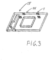
- the steel part 4 is suited for use around a corner 14 of a concrete panel 15, as illustrated in FIG. 3, which can be useful in some applications.
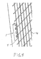
- the height H of this second part 4 of the welding plate 1 and the gaps 13 between the other segments 12 is chosen with respect to the environmental class of the overall concrete structure. As illustrated in FIG. 4, the height may be chosen to allow the normally used reinforcement net 16 to be placed on top of the welding plate with the net extending through the gaps 13.
- the gaps 13 between the teeth-like segments in the welding plate are chosen in accordance with the net mask size.
- FIG 5 A further application is illustrated in FIG 5.
- the tearing strength of the welding plate 1 according to the invention can be improved by through-going reinforcement steels 17 using the holes 19 placed in the segments in the welding plate 1. Size and exact position of these holes can vary from application to application. If no through-going reinforcement steels are used, the holes 19 add to increased tearing strength allowing the liquid concrete to fill the void.
- the thickness of the welding plate 1 is chosen in accordance with the chosen manufacturing method, which is foreseen to be sheet steel bending machine based. With this commonly used production method, a cheaper device can be manufactured, and a more accurate production is possible, compared to welding methods. This increases the quality of the assembly method, since some device uncertainties are removed.
- FIG. 6 illustrates a second embodiment of a profile 1' according to the invention, namely a door frame profile. Taking an approach from a sheet metal manufacturing point of view, the design of a door frame profile is done by machining and bending of a piece of sheet metal.
- a C-shaped cross section is used as basis for the device, best seen on FIG. 8.
- a first part 3 of the C-shaped profile 1' comprises segments 9 as a row of teeth which have end parts 18 that are bent at an angle relative to the first part 3.
- the teeth-like segments 9 are included in the geometry for tearing strength purposes, allowing the liquid concrete to fill the void under the bent end part of the sheet metal flange 3.
- the base 2 of the C-shape is made several times wider than the height of the first 3 and second part 4 of the C-shape.
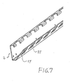
- this base flange 2 As illustrated in FIG. 7, in this base flange 2, a pattern of holes, threads or similar can be pre-manufactured in the base for later mounting purposes.
- the second part of the C-shape is higher, topped by an inward bended third part 11 with large holes 21.
- This third part is incorporated as a flange in the geometry for tearing strength purposes, allowing the liquid concrete to anchor the door frame profile 1' during the distribution in the concrete panel 15 mould.
- cellular foam 22 of EPDM for example self-adhesive, or similar as shown in the cross sectional view of FIG. 9, the pre-manufactured pattern on the inner side 23 is kept free of concrete. Only the teeth-like segment section 24 as well as the inward bended third part 10 is in contact with the concrete, serving as load bearing parts of the profile 1. By choosing a soft cellular profile 22, penetration is possible for screws, rivets or similar.
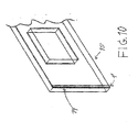
- the design of the door frame profile 1' allows usage on edges of concrete panels 15 as illustrated in more detail in FIG. 10 as well as anywhere on the concrete panel sides. This universal usage is important, since it offers maximum flexibility to the concrete panel designer. Most commonly a door frame profile 1' would be used along one of the concrete panel 15 edges 14, hence making positioning easy since the base part 2 can be placed up against a mould side.
- FIG. 11 An application of the welding plate is illustrated in FIG. 11 showing a compact secondary substation 30 for an electrical apparatus, such as a transformer, comprising a foundation plate 31, two concrete panels 32, 33 provided as walls on opposites sides of the foundation plate 31 and fastened to the foundation plate, a roof 34 covering the space 35 between the two concrete panels 32, 33 and fastened to the panels by welding plates 1.
- an electrical apparatus such as a transformer
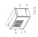
- the concrete panels 32, 33 are provided with openings 36, 37 into which ventilation doors 38, 39 as shown in FIG.12 and FIG. 15 can be mounted.
- a gable 40, 41 at each end of the substation 30 is made of sheet metal parts and comprises a door 42 entrance.
- the substation 30 in form of a transformer house is provided with at least a first room 44 and a second room 45.
- the first room 44 contains the high voltage part of the electricity and the second room 45 contains the low voltage part of the electricity.
- the substation also contains a third room 46 for a transformer 43.
- the transformer 43 is shown in greater detail in FIG. 14 illustrating high voltage connections 47 and low voltage connections 48.
Landscapes
- Engineering & Computer Science (AREA)
- Architecture (AREA)
- Physics & Mathematics (AREA)
- Electromagnetism (AREA)
- Civil Engineering (AREA)
- Structural Engineering (AREA)
- Panels For Use In Building Construction (AREA)
- Securing Of Glass Panes Or The Like (AREA)
- Steps, Ramps, And Handrails (AREA)
- Analysing Materials By The Use Of Radiation (AREA)
- Moulds, Cores, Or Mandrels (AREA)
Abstract
Description
- The present invention relates to a profile, preferably a steel profile, for embedding in a concrete structure to a production method of such a profile and use of such a profile.
- When a structure is made of precast concrete panels, a normal joining procedure is welding. At the connection line of each of the concrete panels, a steel part is moulded into each concrete panel, positioned so that welding is possible, thus creating a rigid connection between the concrete panels.
- These steel parts are not following a standard, but manufactured from application to application. Often, the steel parts are produced locally at the concrete panel manufacturer, who is normally handling the steel reinforcements used in concrete panels. The result is generally improvised solutions, costly and inappropriate steel parts. The most commonly seen device is a flat, massive steel plate with some tubular steel reinforcements welded to the rear side, in order to create tearing strength.
- The geometrical dimensions of the steel part are chosen in order to create sufficient mechanical strength between the concrete panels in the structure, matching the necessary cross section area of the fillet weld. The steel part should also be designed to withstand deformations emerging from the stresses created from the weld heat, and also the concrete can be damaged if the steel part temperature exceeds a concrete type dependent level. These boundaries often lead to choosing steel part thicknesses well above the actually required minimum, and often, the thickness is not subject to analytical calculations in a design phase.
- The steel part should have an application dependent minimum tearing strength, which can be determined analytically. Not often are calculations used to design the tearing properties of a steel part, but occasionally, a practical tension test is performed to prove this. Mostly, bended steel reinforcements are welded onto the rear side of the steel part to increase the tearing strength, but most commonly done intuitively, using the steel reinforcements available.
- When a structure is made of precast concrete panels, a normal procedure for attaching doors and other lightweight components is by using bolts or other threaded components.
- Lightweight components are defined as components that do not load its supporting structure [the concrete panel] with substantial forces. The magnitude of these forces may vary from application to application and should be defined more specifically in each case.
- In most designs the support of lightweight components includes threaded inserts to be placed correctly on the concrete panel mould, or similar steel part devices especially prepared for each application.
- Also, these steel parts are not following a standard, but manufactured from application to application and produced locally at the concrete panel manufacturer. The most commonly seen device is a flat, massive steel plate with threads added to the side placed against the concrete panel mould. The mechanical strength of designs like these is often way above needs, often meaning parts are more expensive than required.
- Using standardized thread inserts, which can be positioned against a concrete panel mould, tends to lower costs to what might be an acceptable level. However, there might be a high effort involved in the positioning of these standardized thread inserts, since these most commonly has tubular shape. Attaching the standardized thread inserts to the concrete panel mould could prove time consuming, with relatively high tolerances involved. Also, there is the possibility of the standardized thread insert to tilt when the liquid concrete is distributed in the concrete panel mould.
- Often the lightweight components require more than one connection point to the supporting structure, meaning that position tolerances between two connection points becomes critical. In the example of attaching a sheet metal door to a concrete panel structure, the upper and lower hinge of the door should be attached in a way securing the door to open and close correctly. If the interrelated distances between the two hinges are not having narrow tolerances, the door would never work properly.
- When producing precast concrete panels, the entire handling of the concrete panel during the production speaks against narrow tolerances. Forces from the vibration of the concrete are significantly, spoiling any accurate positioning of any devices, as does the forces emerging from the distribution of the liquid concrete when being held into the mould.
- The only way that narrow tolerances between more than one connection point in the concrete panel is possible is by using one insert with the tolerances build in. This could be steel part with pre-manufactured threaded holes or similar. This steel part should have sufficient tearing strength to withstand the pullout forces when mounting e.g. a sheet metal door, and should be manufactured in a way allowing narrow tolerances. Costs are certainly a concern as well.
- It is therefore the object of the invention to provide a profile for concrete structures not having the aforementioned disadvantages. In particular, it is the purpose of the invention to provide a profile to be embedded in the concrete during manufacturing of the concrete structure, where the profile is easy to manufacture at low cost, implies a high degree of flexibility to the concrete panel designer and can withstand a high tearing strength when embedded in the concrete structure.
- This purpose is achieved with a profile for embedding in a concrete structure during moulding, the profile having a cross section which is generally U shaped or C-shaped with a base and a first and a second part extending laterally from opposite edges of the base to form the legs of the U shaped or C-shaped cross section, wherein the first part has a row of segments resembling a teeth-like structure along the edge of the base and the second part extends into a third part that is bend at an angle relatively to the second part.
- Experiments have revealed that the profile is easy to manufacture at low cost, implies a high degree of flexibility to the concrete panel designer and can withstand a high tearing strength when embedded in the concrete structure. For example, it is suited as welding plates in order to fasten concrete panels to foundation plates of compact secondary substation, such as transformer houses. Other applications are as door frames moulded into concrete panels, for example as used in compact secondary substation, such as transformer houses.
- The design of the profile allows usage on edges of concrete panels as well as anywhere on the concrete panel sides. This universal usage is important, since it offers maximum flexibility to the concrete panel designer without compromising an industrialized solution with respect to production.
- In a further embodiment, the base is flat and the first and the second part extend laterally at a right angle from the base. In an even further embodiment, the end parts of the segments are bent at an angle. Each of the segments may have at least one hole.
- In order for the profiles to be combined with reinforcement material in concrete structures, the gaps between the segments may be adapted in accordance with a net mask size of a metal net used for reinforcement of the concrete structure.
- In order for the third part to have a high tearing strength when embedded in the concrete, the third part may have a row of holes along the base in order to accommodate concrete inside these holes.
- In a further embodiment, the third part has other segments in a teeth-like structure. For example, the gaps between the other segments are adapted in accordance with a net mask size of a metal net used for reinforcement of the concrete structure. Each of the segments may, for instance, have one of the other segments as a counterpart with equal distances from one end of the profile. In addition, the third part may be bent at an angle of between 25 and 65 degrees, preferably between 25 and 55 degrees, for example bent at an angle of around 45 degrees.
- In a preferred embodiment, the base is more than two times and less than 5 times, for example around 3 times, wider than the height of the legs of the U-shaped or C-shaped cross section. In addition, the length of the base may be at least 2 times larger than its width, for example around 3 times its width.
- Such a profile may be made of a bent sheet of metal.
- A profile according to the invention may be used in combination with a compact secondary substation (CCS) for an electrical apparatus, such as a transformer, comprising a foundation plate, two concrete panels provided as walls on opposites sides of the foundation plate and fastened to the foundation plate, a roof covering the space between the two concrete panels and connected to the panels, a gable at each end of the substation, wherein at least one of the gables is made of sheet metal parts and comprise a door entrance, wherein the profile is moulded into at least one of the concrete panels.
- Pre-cast concrete panels according to the invention are easy to manufacture, for example as flat walls. They can be made without the necessity of a pre-manufactured mould, using only a flat bedplate as moulding surface. Chipboard sides may be erected on the bedplate, creating a one-off mould that eventually is torn apart when the concrete panel is de-moulded. Reinforcements, inserts and other parts to be moulded into the concrete panel are placed with coarse tolerances before the mould is filled with concrete.
- Using this flexible manufacturing method, a Concrete CSS can be erected. Moulded into the different concrete panels creating the overall structure a number of welding plates allows the concrete panels to be welded together. By adding a flexible door panel profile made of machined and bended sheet metal, lightweight doors can be attached in a precise way. As a frame for the doors, profiles according to the invention may successfully be used.
- For example, the substation is a transformer house with at least a first and a second room, wherein the first room contains the high voltage part of the electricity and the second room contains the low voltage part of the electricity. In addition, the substation may also contain a third room for the transformer. Consisting of a minimum of three different rooms - the low voltage room, the high voltage room and the transformer room - the overall layout of a CSS can be made simple. Each of the gable ends of the housing may be made entirely of sheet metal parts, allowing full access to the electrical equipment in the low voltage and the high voltage rooms. In the middle of the CSS the transformer may be placed, with access through ventilation doors integrated in the concrete panels. When installing the transformer, the roof can be lifted off the structure as the roof of the substations is mounted detachable.
- It should be noted that the above described substation with concrete panels as walls is of a general nature and may be constructed without the profile of the invention.
- The invention will be explained in more detail with reference to the drawing, where
- FIG. 1
- is an image of a first embodiment of the invention suited as a welding plate,
- FIG. 2
- shows the embodiment of FIG. 1 in an end view,
- FIG. 3
- shows the embodiment of FIG. 1 implemented in a concrete panel,
- FIG. 4
- illustrates the moulding of the embodiment of FIG. 1 in a concrete panel,
- FIG. 5
- shows the embodiment of FIG. 1 implemented together with reinforcement material between the segments,
- FIG. 6
- is an image of a second embodiment of the invention suited as a door panel,
- FIG. 7
- shows the embodiment of FIG. 6 in a different perspective view,
- FIG. 8
- shows the embodiment of FIG. 6 in an end view,
- FIG. 9
- shows the embodiment of FIG. 6 in an end view with a polymer slab inserted,
- FIG. 10
- illustrates an application of the embodiment of FIG. 6 as an edge protector,
- FIG. 11
- illustrates an application in a compact secondary substations for an electrical apparatus transformer,
- FIG. 12
- illustrates the transformer station with gable doors and ventilation doors,
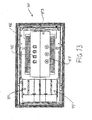
- FIG. 13
- shows the transformer station in perspective with transparent roof,
- FIG. 14
- shows the transformer station in perspective with transparent roof in a different perspective,
- FIG. 15
- shows the transformer station in perspective with transparent roof in a further different perspective.
- FIG. 1 is an image of a profile/welding plate 1 according to the invention in a first embodiment suited as a welding plate, which is generally U shaped with a
straight base 2 and a first 3 and asecond part 4 extending laterally fromopposite edges base 2 to form thelegs 7, 8 of the U shaped or cross section, which is illustrated by the end section in FIG. 2. The profile 1 has a length L, a width W and a height H. - The first part 3 has a row of segments 9 resembling a teeth-like structure along the
edge 6 of thebase 2 withgaps 13 between the segments. Thesecond part 4 extends into athird part 10 that is bent at an angle 11 relatively to thesecond part 4. In the figure, thethird part 10 is angled at 45 degrees relatively to thesecond part 4. Thethird part 10 comprisesother segments 12 matching the row of segments 9 from the first part 3 of the U-shape. This row ofother segments 12 is angled 45 degrees inwards in the cross section, in order to minimize the circumscribed circle. The length L of the profile is approximately three times the width W of the profile. - Taking an approach from a sheet steel manufacturing point of view, the design of a welding plate is done by machining and bending of a piece of sheet steel.
- As illustrated in FIG. 1, all of the segments 9 have through-going holes 19 for tearing strength purposes. The
base 2 of the U-shape has a width W which is approximately three times wider than the height H of the U-shape side. However, accurate dimensions of the profile can vary from application to application, as can the ratios mentioned. - By letting the
second part 4 of the welding plate 1 be rigid and without holes, thesteel part 4 is suited for use around acorner 14 of aconcrete panel 15, as illustrated in FIG. 3, which can be useful in some applications. - The height H of this
second part 4 of the welding plate 1 and thegaps 13 between theother segments 12 is chosen with respect to the environmental class of the overall concrete structure. As illustrated in FIG. 4, the height may be chosen to allow the normally used reinforcement net 16 to be placed on top of the welding plate with the net extending through thegaps 13. Thegaps 13 between the teeth-like segments in the welding plate are chosen in accordance with the net mask size. - A further application is illustrated in FIG 5. The tearing strength of the welding plate 1 according to the invention can be improved by through-going reinforcement steels 17 using the holes 19 placed in the segments in the welding plate 1. Size and exact position of these holes can vary from application to application. If no through-going reinforcement steels are used, the holes 19 add to increased tearing strength allowing the liquid concrete to fill the void.
- The thickness of the welding plate 1 is chosen in accordance with the chosen manufacturing method, which is foreseen to be sheet steel bending machine based. With this commonly used production method, a cheaper device can be manufactured, and a more accurate production is possible, compared to welding methods. This increases the quality of the assembly method, since some device uncertainties are removed.
- FIG. 6 illustrates a second embodiment of a profile 1' according to the invention, namely a door frame profile. Taking an approach from a sheet metal manufacturing point of view, the design of a door frame profile is done by machining and bending of a piece of sheet metal.
- A C-shaped cross section is used as basis for the device, best seen on FIG. 8. With reference to FIG. 6, a first part 3 of the C-shaped profile 1' comprises segments 9 as a row of teeth which have end parts 18 that are bent at an angle relative to the first part 3. The teeth-like segments 9 are included in the geometry for tearing strength purposes, allowing the liquid concrete to fill the void under the bent end part of the sheet metal flange 3. The
base 2 of the C-shape is made several times wider than the height of the first 3 andsecond part 4 of the C-shape. - As illustrated in FIG. 7, in this
base flange 2, a pattern of holes, threads or similar can be pre-manufactured in the base for later mounting purposes. The second part of the C-shape is higher, topped by an inward bended third part 11 withlarge holes 21. This third part is incorporated as a flange in the geometry for tearing strength purposes, allowing the liquid concrete to anchor the door frame profile 1' during the distribution in theconcrete panel 15 mould. - Accurate dimensions of the door frame profile would vary from application to application.
- By using cellular foam 22 of EPDM, for example self-adhesive, or similar as shown in the cross sectional view of FIG. 9, the pre-manufactured pattern on the
inner side 23 is kept free of concrete. Only the teeth-like segment section 24 as well as the inward bendedthird part 10 is in contact with the concrete, serving as load bearing parts of the profile 1. By choosing a soft cellular profile 22, penetration is possible for screws, rivets or similar. - The design of the door frame profile 1' allows usage on edges of
concrete panels 15 as illustrated in more detail in FIG. 10 as well as anywhere on the concrete panel sides. This universal usage is important, since it offers maximum flexibility to the concrete panel designer. Most commonly a door frame profile 1' would be used along one of theconcrete panel 15edges 14, hence making positioning easy since thebase part 2 can be placed up against a mould side. - The combination of a sheet metal profile, pre-manufactured by computer numerical machinery, and an accurate positioning of the door frame profile 1' is resulting in very high quality assembly results. The usage in e.g. mounting of doors has proven very well, with low effort in manufacturing the
concrete panel 15 and a cost-effective door frame profile 1'. - An application of the welding plate is illustrated in FIG. 11 showing a compact
secondary substation 30 for an electrical apparatus, such as a transformer, comprising afoundation plate 31, twoconcrete panels foundation plate 31 and fastened to the foundation plate, aroof 34 covering the space 35 between the twoconcrete panels - The
concrete panels openings ventilation doors 38, 39 as shown in FIG.12 and FIG. 15 can be mounted. As best seen in FIG. 11 in combination with FIG. 12, agable 40, 41 at each end of thesubstation 30 is made of sheet metal parts and comprises adoor 42 entrance. As best seen in FIG. 13 in combination with FIG. 14 and FIG. 15 thesubstation 30 in form of a transformer house is provided with at least a first room 44 and asecond room 45. The first room 44 contains the high voltage part of the electricity and thesecond room 45 contains the low voltage part of the electricity. In addition, the substation also contains athird room 46 for atransformer 43. Consisting of a minimum of three different rooms - the high voltage room 44, thelow voltage room 45 and the transformer room 46 - the overall layout of a CSS can be made simple. Thetransformer 43 is shown in greater detail in FIG. 14 illustratinghigh voltage connections 47 andlow voltage connections 48.
Claims (19)
- A profile for embedding in a concrete structure during moulding, the profile having a cross section which is generally U shaped or C-shaped with a base and a first and a second part extending laterally from opposite edges of the base to form the legs of the U shaped or C-shaped cross section, wherein the first part has a row of segments resembling a teeth-like structure along the edge of the base and the second part extends into a third part that is bend at an angle relatively to the second part.
- A profile according to claim 1, wherein the base is flat and the first and the second part extend laterally at a right angle from the base.
- A profile according to claim 1 or 2, wherein an end part of the segments are bend at an angle.
- A profile according to any preceding claim, wherein the each of the segments have at least one hole.
- A profile according to any preceding claim, wherein the gaps between the segments are adapted in accordance with a net mask size of a metal net used for reinforcement of the concrete structure.
- A profile according to any preceding claim, wherein the third part has a row of holes along the base.
- A profile according to any preceding claim, wherein the third part has other segments in a teeth-like structure.
- A profile according to claim 7, wherein the gaps between the other segments are adapted in accordance with a net mask size of a metal net used for reinforcement of the concrete structure.
- A profile according to claim 7 or 8, wherein each of the segments has one of the other segments as a counterpart with equal distances from one end of the profile.
- A profile according to any preceding claim, wherein the third part is bent at an angle of between 25 and 65 degrees.
- A profile according to claim 10, wherein the third part is bent at an angle of around 45 degrees.
- A profile according to any preceding claim, wherein the base is more than two times wider and less than 5 times wider than the height of the legs of the U-shaped or C-shaped cross section.
- A profile according to claim 12, wherein the base is around three times wider than the height of the legs of the U-shaped or C-shaped cross section.
- A profile according to any preceding claim, wherein length of the base is at least 2 times larger than its width.
- A profile according to any preceding claim, wherein the length of base is around 3 times its width.
- A profile according to any preceding claim made of a bent sheet of metal.
- A profile according to anyone of the claims 1-16 in combination with a compact secondary substation for an electrical apparatus, such as a transformer, comprising a foundation plate, two concrete panels provided as walls on opposites sides of the foundation plate and fastened to the foundation plate, a roof covering the space between the two concrete panels and fastened to the panels, a gable at each end of the substation, wherein at least one of the gables is made of sheet metal parts and comprise a door entrance, wherein the profile is moulded into at least one of the concrete panels.
- Use of a profile according to anyone of the claims 1-16 as a welding plate in a Compact secondary substation, such as a transformer station, for fastening moulded concrete panels to a foundation plate.
- Use of a profile according to anyone of the claims 1-16 as a door frame profile moulded into a concrete panel.
Priority Applications (4)
| Application Number | Priority Date | Filing Date | Title |
|---|---|---|---|
| DE602005024033T DE602005024033D1 (en) | 2005-12-29 | 2005-12-29 | Profile for a concrete element and the use of the profile |
| EP05028689A EP1803861B1 (en) | 2005-12-29 | 2005-12-29 | Profile for concrete structure and use of said profile |
| AT05028689T ATE483863T1 (en) | 2005-12-29 | 2005-12-29 | PROFILE FOR A CONCRETE ELEMENT AND THE USE OF THE PROFILE |
| CN2006101682126A CN1990969B (en) | 2005-12-29 | 2006-12-26 | Profile for concrete structure |
Applications Claiming Priority (1)
| Application Number | Priority Date | Filing Date | Title |
|---|---|---|---|
| EP05028689A EP1803861B1 (en) | 2005-12-29 | 2005-12-29 | Profile for concrete structure and use of said profile |
Publications (2)
| Publication Number | Publication Date |
|---|---|
| EP1803861A1 true EP1803861A1 (en) | 2007-07-04 |
| EP1803861B1 EP1803861B1 (en) | 2010-10-06 |
Family
ID=35701302
Family Applications (1)
| Application Number | Title | Priority Date | Filing Date |
|---|---|---|---|
| EP05028689A Expired - Lifetime EP1803861B1 (en) | 2005-12-29 | 2005-12-29 | Profile for concrete structure and use of said profile |
Country Status (4)
| Country | Link |
|---|---|
| EP (1) | EP1803861B1 (en) |
| CN (1) | CN1990969B (en) |
| AT (1) | ATE483863T1 (en) |
| DE (1) | DE602005024033D1 (en) |
Families Citing this family (1)
| Publication number | Priority date | Publication date | Assignee | Title |
|---|---|---|---|---|
| CN117266378A (en) * | 2023-11-22 | 2023-12-22 | 享城科建(北京)科技发展有限公司 | Built-in fitting |
Citations (4)
| Publication number | Priority date | Publication date | Assignee | Title |
|---|---|---|---|---|
| US1562784A (en) * | 1922-03-23 | 1925-11-24 | Rudolph K Olsen | Anchor strip for securing finishing structures to concrete |
| US3574984A (en) * | 1969-02-10 | 1971-04-13 | Illinois Tool Works | Corner insert device |
| US4905444A (en) * | 1989-06-12 | 1990-03-06 | Connection Specialties Inc. | Method and system for mounting building wall panels to building frames, incorporating mounting means elements with two degrees of motion freedom |
| DE10001621A1 (en) * | 2000-01-17 | 2001-10-31 | Beton Elemente Und Baustoffwer | Kit for compact station building, e.g. for transformer stations, has connecting devices, side walls extending, connecting devices, corner connecting devices, side elements and roof plate |
Family Cites Families (4)
| Publication number | Priority date | Publication date | Assignee | Title |
|---|---|---|---|---|
| US3394516A (en) * | 1965-07-06 | 1968-07-30 | Armco Steel Corp | Spacer |
| US4753053A (en) * | 1985-11-29 | 1988-06-28 | Robert J. Jenkins | Anchor for erosion resistant refractory lining |
| GB9525880D0 (en) * | 1995-12-19 | 1996-02-21 | Limited | Channel |
| US6874288B1 (en) * | 2003-02-03 | 2005-04-05 | Crete-Form, Inc | Concrete deck depression form system |
-
2005
- 2005-12-29 AT AT05028689T patent/ATE483863T1/en not_active IP Right Cessation
- 2005-12-29 DE DE602005024033T patent/DE602005024033D1/en not_active Expired - Lifetime
- 2005-12-29 EP EP05028689A patent/EP1803861B1/en not_active Expired - Lifetime
-
2006
- 2006-12-26 CN CN2006101682126A patent/CN1990969B/en active Active
Patent Citations (4)
| Publication number | Priority date | Publication date | Assignee | Title |
|---|---|---|---|---|
| US1562784A (en) * | 1922-03-23 | 1925-11-24 | Rudolph K Olsen | Anchor strip for securing finishing structures to concrete |
| US3574984A (en) * | 1969-02-10 | 1971-04-13 | Illinois Tool Works | Corner insert device |
| US4905444A (en) * | 1989-06-12 | 1990-03-06 | Connection Specialties Inc. | Method and system for mounting building wall panels to building frames, incorporating mounting means elements with two degrees of motion freedom |
| DE10001621A1 (en) * | 2000-01-17 | 2001-10-31 | Beton Elemente Und Baustoffwer | Kit for compact station building, e.g. for transformer stations, has connecting devices, side walls extending, connecting devices, corner connecting devices, side elements and roof plate |
Also Published As
| Publication number | Publication date |
|---|---|
| DE602005024033D1 (en) | 2010-11-18 |
| EP1803861B1 (en) | 2010-10-06 |
| ATE483863T1 (en) | 2010-10-15 |
| CN1990969B (en) | 2011-03-23 |
| CN1990969A (en) | 2007-07-04 |
Similar Documents
| Publication | Publication Date | Title |
|---|---|---|
| US6745814B2 (en) | Guide track assemblies and mounting brackets for upward acting doors | |
| EP1126101A1 (en) | Mounting structure and method for viscosity system damping wall | |
| US6457284B1 (en) | Structure for installing a viscous vibration damping wall and method of installing the same | |
| US6601350B1 (en) | Structure for installing a viscous vibration-damping wall and method of installing the same | |
| SK19812000A3 (en) | Multipurpose connection console for material handling gate | |
| EP1803861B1 (en) | Profile for concrete structure and use of said profile | |
| EP1803872B1 (en) | Concrete structure and method of construction | |
| JP2008274651A (en) | ALC buried anchor bracket, ALC panel and ALC panel mounting structure | |
| KR102356035B1 (en) | Modular frame combining structure provided with post-tension | |
| MXPA06014893A (en) | Joist support . | |
| US20220381051A1 (en) | Outdoor seismic equipment enclosures | |
| JP2015139338A (en) | Fittings | |
| KR20190012585A (en) | Cable tray rung and its manufacturing method | |
| KR100430600B1 (en) | Inspective Handrail-bracket of bridge | |
| CN101847449B (en) | Frame for supporting housing | |
| JP2007046305A (en) | Mounting hardware for SC structure | |
| CN219138230U (en) | Wall assembled fossil fragments mounting structure | |
| CN100456912C (en) | Mounting accessories for cabinets | |
| CN223401891U (en) | Construction structure of grounding point for side lightning protection of high-rise buildings | |
| CN215858236U (en) | Base and container room | |
| JPH0344883Y2 (en) | ||
| JPS6213981Y2 (en) | ||
| JP3965090B2 (en) | Formwork forming unit and formwork forming method using the formwork forming unit | |
| JP3710781B2 (en) | Formwork forming unit and formwork forming method using the formwork forming unit | |
| JPH10252146A (en) | Joint metal fittings for building |
Legal Events
| Date | Code | Title | Description |
|---|---|---|---|
| PUAI | Public reference made under article 153(3) epc to a published international application that has entered the european phase |
Free format text: ORIGINAL CODE: 0009012 |
|
| AK | Designated contracting states |
Kind code of ref document: A1 Designated state(s): AT BE BG CH CY CZ DE DK EE ES FI FR GB GR HU IE IS IT LI LT LU LV MC NL PL PT RO SE SI SK TR |
|
| AX | Request for extension of the european patent |
Extension state: AL BA HR MK YU |
|
| 17P | Request for examination filed |
Effective date: 20071126 |
|
| 17Q | First examination report despatched |
Effective date: 20080103 |
|
| AKX | Designation fees paid |
Designated state(s): AT BE BG CH CY CZ DE DK EE ES FI FR GB GR HU IE IS IT LI LT LU LV MC NL PL PT RO SE SI SK TR |
|
| GRAP | Despatch of communication of intention to grant a patent |
Free format text: ORIGINAL CODE: EPIDOSNIGR1 |
|
| GRAS | Grant fee paid |
Free format text: ORIGINAL CODE: EPIDOSNIGR3 |
|
| GRAA | (expected) grant |
Free format text: ORIGINAL CODE: 0009210 |
|
| AK | Designated contracting states |
Kind code of ref document: B1 Designated state(s): AT BE BG CH CY CZ DE DK EE ES FI FR GB GR HU IE IS IT LI LT LU LV MC NL PL PT RO SE SI SK TR |
|
| REG | Reference to a national code |
Ref country code: GB Ref legal event code: FG4D |
|
| REG | Reference to a national code |
Ref country code: CH Ref legal event code: EP |
|
| REG | Reference to a national code |
Ref country code: IE Ref legal event code: FG4D |
|
| REF | Corresponds to: |
Ref document number: 602005024033 Country of ref document: DE Date of ref document: 20101118 Kind code of ref document: P |
|
| REG | Reference to a national code |
Ref country code: SE Ref legal event code: TRGR |
|
| REG | Reference to a national code |
Ref country code: NL Ref legal event code: VDEP Effective date: 20101006 |
|
| PG25 | Lapsed in a contracting state [announced via postgrant information from national office to epo] |
Ref country code: SI Free format text: LAPSE BECAUSE OF FAILURE TO SUBMIT A TRANSLATION OF THE DESCRIPTION OR TO PAY THE FEE WITHIN THE PRESCRIBED TIME-LIMIT Effective date: 20101006 |
|
| LTIE | Lt: invalidation of european patent or patent extension |
Effective date: 20101006 |
|
| PG25 | Lapsed in a contracting state [announced via postgrant information from national office to epo] |
Ref country code: LT Free format text: LAPSE BECAUSE OF FAILURE TO SUBMIT A TRANSLATION OF THE DESCRIPTION OR TO PAY THE FEE WITHIN THE PRESCRIBED TIME-LIMIT Effective date: 20101006 |
|
| PG25 | Lapsed in a contracting state [announced via postgrant information from national office to epo] |
Ref country code: BG Free format text: LAPSE BECAUSE OF FAILURE TO SUBMIT A TRANSLATION OF THE DESCRIPTION OR TO PAY THE FEE WITHIN THE PRESCRIBED TIME-LIMIT Effective date: 20110106 Ref country code: AT Free format text: LAPSE BECAUSE OF FAILURE TO SUBMIT A TRANSLATION OF THE DESCRIPTION OR TO PAY THE FEE WITHIN THE PRESCRIBED TIME-LIMIT Effective date: 20101006 Ref country code: FI Free format text: LAPSE BECAUSE OF FAILURE TO SUBMIT A TRANSLATION OF THE DESCRIPTION OR TO PAY THE FEE WITHIN THE PRESCRIBED TIME-LIMIT Effective date: 20101006 Ref country code: NL Free format text: LAPSE BECAUSE OF FAILURE TO SUBMIT A TRANSLATION OF THE DESCRIPTION OR TO PAY THE FEE WITHIN THE PRESCRIBED TIME-LIMIT Effective date: 20101006 Ref country code: IS Free format text: LAPSE BECAUSE OF FAILURE TO SUBMIT A TRANSLATION OF THE DESCRIPTION OR TO PAY THE FEE WITHIN THE PRESCRIBED TIME-LIMIT Effective date: 20110206 Ref country code: LV Free format text: LAPSE BECAUSE OF FAILURE TO SUBMIT A TRANSLATION OF THE DESCRIPTION OR TO PAY THE FEE WITHIN THE PRESCRIBED TIME-LIMIT Effective date: 20101006 Ref country code: PT Free format text: LAPSE BECAUSE OF FAILURE TO SUBMIT A TRANSLATION OF THE DESCRIPTION OR TO PAY THE FEE WITHIN THE PRESCRIBED TIME-LIMIT Effective date: 20110207 |
|
| PG25 | Lapsed in a contracting state [announced via postgrant information from national office to epo] |
Ref country code: BE Free format text: LAPSE BECAUSE OF FAILURE TO SUBMIT A TRANSLATION OF THE DESCRIPTION OR TO PAY THE FEE WITHIN THE PRESCRIBED TIME-LIMIT Effective date: 20101006 Ref country code: GR Free format text: LAPSE BECAUSE OF FAILURE TO SUBMIT A TRANSLATION OF THE DESCRIPTION OR TO PAY THE FEE WITHIN THE PRESCRIBED TIME-LIMIT Effective date: 20110107 |
|
| PG25 | Lapsed in a contracting state [announced via postgrant information from national office to epo] |
Ref country code: ES Free format text: LAPSE BECAUSE OF FAILURE TO SUBMIT A TRANSLATION OF THE DESCRIPTION OR TO PAY THE FEE WITHIN THE PRESCRIBED TIME-LIMIT Effective date: 20110117 Ref country code: MC Free format text: LAPSE BECAUSE OF NON-PAYMENT OF DUE FEES Effective date: 20101231 Ref country code: CZ Free format text: LAPSE BECAUSE OF FAILURE TO SUBMIT A TRANSLATION OF THE DESCRIPTION OR TO PAY THE FEE WITHIN THE PRESCRIBED TIME-LIMIT Effective date: 20101006 Ref country code: EE Free format text: LAPSE BECAUSE OF FAILURE TO SUBMIT A TRANSLATION OF THE DESCRIPTION OR TO PAY THE FEE WITHIN THE PRESCRIBED TIME-LIMIT Effective date: 20101006 |
|
| REG | Reference to a national code |
Ref country code: CH Ref legal event code: PL |
|
| PLBE | No opposition filed within time limit |
Free format text: ORIGINAL CODE: 0009261 |
|
| STAA | Information on the status of an ep patent application or granted ep patent |
Free format text: STATUS: NO OPPOSITION FILED WITHIN TIME LIMIT |
|
| PG25 | Lapsed in a contracting state [announced via postgrant information from national office to epo] |
Ref country code: PL Free format text: LAPSE BECAUSE OF FAILURE TO SUBMIT A TRANSLATION OF THE DESCRIPTION OR TO PAY THE FEE WITHIN THE PRESCRIBED TIME-LIMIT Effective date: 20101006 Ref country code: DK Free format text: LAPSE BECAUSE OF FAILURE TO SUBMIT A TRANSLATION OF THE DESCRIPTION OR TO PAY THE FEE WITHIN THE PRESCRIBED TIME-LIMIT Effective date: 20101006 Ref country code: RO Free format text: LAPSE BECAUSE OF FAILURE TO SUBMIT A TRANSLATION OF THE DESCRIPTION OR TO PAY THE FEE WITHIN THE PRESCRIBED TIME-LIMIT Effective date: 20101006 Ref country code: SK Free format text: LAPSE BECAUSE OF FAILURE TO SUBMIT A TRANSLATION OF THE DESCRIPTION OR TO PAY THE FEE WITHIN THE PRESCRIBED TIME-LIMIT Effective date: 20101006 |
|
| 26N | No opposition filed |
Effective date: 20110707 |
|
| GBPC | Gb: european patent ceased through non-payment of renewal fee |
Effective date: 20110106 |
|
| PG25 | Lapsed in a contracting state [announced via postgrant information from national office to epo] |
Ref country code: CH Free format text: LAPSE BECAUSE OF NON-PAYMENT OF DUE FEES Effective date: 20101231 Ref country code: IE Free format text: LAPSE BECAUSE OF NON-PAYMENT OF DUE FEES Effective date: 20101229 Ref country code: LI Free format text: LAPSE BECAUSE OF NON-PAYMENT OF DUE FEES Effective date: 20101231 |
|
| REG | Reference to a national code |
Ref country code: DE Ref legal event code: R097 Ref document number: 602005024033 Country of ref document: DE Effective date: 20110707 |
|
| PG25 | Lapsed in a contracting state [announced via postgrant information from national office to epo] |
Ref country code: GB Free format text: LAPSE BECAUSE OF NON-PAYMENT OF DUE FEES Effective date: 20110106 |
|
| PG25 | Lapsed in a contracting state [announced via postgrant information from national office to epo] |
Ref country code: CY Free format text: LAPSE BECAUSE OF FAILURE TO SUBMIT A TRANSLATION OF THE DESCRIPTION OR TO PAY THE FEE WITHIN THE PRESCRIBED TIME-LIMIT Effective date: 20101006 |
|
| PG25 | Lapsed in a contracting state [announced via postgrant information from national office to epo] |
Ref country code: LU Free format text: LAPSE BECAUSE OF NON-PAYMENT OF DUE FEES Effective date: 20101229 Ref country code: HU Free format text: LAPSE BECAUSE OF FAILURE TO SUBMIT A TRANSLATION OF THE DESCRIPTION OR TO PAY THE FEE WITHIN THE PRESCRIBED TIME-LIMIT Effective date: 20110407 |
|
| PG25 | Lapsed in a contracting state [announced via postgrant information from national office to epo] |
Ref country code: TR Free format text: LAPSE BECAUSE OF FAILURE TO SUBMIT A TRANSLATION OF THE DESCRIPTION OR TO PAY THE FEE WITHIN THE PRESCRIBED TIME-LIMIT Effective date: 20101006 |
|
| REG | Reference to a national code |
Ref country code: FR Ref legal event code: PLFP Year of fee payment: 11 |
|
| REG | Reference to a national code |
Ref country code: FR Ref legal event code: PLFP Year of fee payment: 12 |
|
| REG | Reference to a national code |
Ref country code: DE Ref legal event code: R082 Ref document number: 602005024033 Country of ref document: DE Representative=s name: MEISSNER BOLTE PATENTANWAELTE RECHTSANWAELTE P, DE Ref country code: DE Ref legal event code: R081 Ref document number: 602005024033 Country of ref document: DE Owner name: ABB SCHWEIZ AG, CH Free format text: FORMER OWNER: ABB TECHNOLOGY AG, ZUERICH, CH |
|
| REG | Reference to a national code |
Ref country code: FR Ref legal event code: PLFP Year of fee payment: 13 |
|
| REG | Reference to a national code |
Ref country code: FR Ref legal event code: TP Owner name: ABB SCHWEIZ AG, CH Effective date: 20180912 |
|
| PGFP | Annual fee paid to national office [announced via postgrant information from national office to epo] |
Ref country code: DE Payment date: 20241210 Year of fee payment: 20 |
|
| PGFP | Annual fee paid to national office [announced via postgrant information from national office to epo] |
Ref country code: FR Payment date: 20241223 Year of fee payment: 20 |
|
| PGFP | Annual fee paid to national office [announced via postgrant information from national office to epo] |
Ref country code: SE Payment date: 20241219 Year of fee payment: 20 |
|
| PGFP | Annual fee paid to national office [announced via postgrant information from national office to epo] |
Ref country code: IT Payment date: 20241227 Year of fee payment: 20 |
|
| REG | Reference to a national code |
Ref country code: DE Ref legal event code: R071 Ref document number: 602005024033 Country of ref document: DE |
|
| REG | Reference to a national code |
Ref country code: SE Ref legal event code: EUG |