EP1803666A1 - Transporting apparatus and method for manufacturing honeycomb structured body - Google Patents
Transporting apparatus and method for manufacturing honeycomb structured body Download PDFInfo
- Publication number
- EP1803666A1 EP1803666A1 EP06022941A EP06022941A EP1803666A1 EP 1803666 A1 EP1803666 A1 EP 1803666A1 EP 06022941 A EP06022941 A EP 06022941A EP 06022941 A EP06022941 A EP 06022941A EP 1803666 A1 EP1803666 A1 EP 1803666A1
- Authority
- EP
- European Patent Office
- Prior art keywords
- transporting
- wet mixture
- transporting apparatus
- storage unit
- honeycomb structured
- Prior art date
- Legal status (The legal status is an assumption and is not a legal conclusion. Google has not performed a legal analysis and makes no representation as to the accuracy of the status listed.)
- Withdrawn
Links
- 238000000034 method Methods 0.000 title claims description 109
- 238000004519 manufacturing process Methods 0.000 title claims description 59
- 239000000203 mixture Substances 0.000 claims abstract description 149
- 238000003860 storage Methods 0.000 claims abstract description 74
- 238000001125 extrusion Methods 0.000 claims description 37
- 230000007246 mechanism Effects 0.000 claims description 27
- 210000004027 cell Anatomy 0.000 claims description 25
- 238000009826 distribution Methods 0.000 claims description 23
- 239000000843 powder Substances 0.000 claims description 17
- 210000002421 cell wall Anatomy 0.000 claims description 10
- 238000010304 firing Methods 0.000 claims description 9
- 239000003566 sealing material Substances 0.000 description 28
- 238000007599 discharging Methods 0.000 description 27
- 239000010410 layer Substances 0.000 description 26
- 239000000919 ceramic Substances 0.000 description 25
- 238000000465 moulding Methods 0.000 description 23
- HBMJWWWQQXIZIP-UHFFFAOYSA-N silicon carbide Chemical compound [Si+]#[C-] HBMJWWWQQXIZIP-UHFFFAOYSA-N 0.000 description 20
- PNEYBMLMFCGWSK-UHFFFAOYSA-N aluminium oxide Inorganic materials [O-2].[O-2].[O-2].[Al+3].[Al+3] PNEYBMLMFCGWSK-UHFFFAOYSA-N 0.000 description 19
- 239000000463 material Substances 0.000 description 19
- 229910010271 silicon carbide Inorganic materials 0.000 description 16
- 239000011230 binding agent Substances 0.000 description 15
- 239000002245 particle Substances 0.000 description 15
- 239000003054 catalyst Substances 0.000 description 10
- 238000002156 mixing Methods 0.000 description 10
- 239000012790 adhesive layer Substances 0.000 description 7
- -1 alumina Chemical compound 0.000 description 7
- 239000000835 fiber Substances 0.000 description 7
- 239000007789 gas Substances 0.000 description 7
- 229910010293 ceramic material Inorganic materials 0.000 description 6
- 229920002134 Carboxymethyl cellulose Polymers 0.000 description 5
- XUIMIQQOPSSXEZ-UHFFFAOYSA-N Silicon Chemical compound [Si] XUIMIQQOPSSXEZ-UHFFFAOYSA-N 0.000 description 5
- 239000001768 carboxy methyl cellulose Substances 0.000 description 5
- 235000010948 carboxy methyl cellulose Nutrition 0.000 description 5
- 239000008112 carboxymethyl-cellulose Substances 0.000 description 5
- 229940105329 carboxymethylcellulose Drugs 0.000 description 5
- 239000010954 inorganic particle Substances 0.000 description 5
- 239000000314 lubricant Substances 0.000 description 5
- 229910052751 metal Inorganic materials 0.000 description 5
- 239000002184 metal Substances 0.000 description 5
- 229920000609 methyl cellulose Polymers 0.000 description 5
- 239000001923 methylcellulose Substances 0.000 description 5
- 235000010981 methylcellulose Nutrition 0.000 description 5
- 239000011812 mixed powder Substances 0.000 description 5
- BASFCYQUMIYNBI-UHFFFAOYSA-N platinum Chemical compound [Pt] BASFCYQUMIYNBI-UHFFFAOYSA-N 0.000 description 5
- 239000011148 porous material Substances 0.000 description 5
- 229910052710 silicon Inorganic materials 0.000 description 5
- 239000010703 silicon Substances 0.000 description 5
- 230000032258 transport Effects 0.000 description 5
- XLYOFNOQVPJJNP-UHFFFAOYSA-N water Substances O XLYOFNOQVPJJNP-UHFFFAOYSA-N 0.000 description 5
- PEDCQBHIVMGVHV-UHFFFAOYSA-N Glycerine Chemical compound OCC(O)CO PEDCQBHIVMGVHV-UHFFFAOYSA-N 0.000 description 4
- OKKJLVBELUTLKV-UHFFFAOYSA-N Methanol Chemical compound OC OKKJLVBELUTLKV-UHFFFAOYSA-N 0.000 description 4
- VYPSYNLAJGMNEJ-UHFFFAOYSA-N Silicium dioxide Chemical compound O=[Si]=O VYPSYNLAJGMNEJ-UHFFFAOYSA-N 0.000 description 4
- 230000015556 catabolic process Effects 0.000 description 4
- 230000002950 deficient Effects 0.000 description 4
- 238000006731 degradation reaction Methods 0.000 description 4
- 238000005238 degreasing Methods 0.000 description 4
- KZHJGOXRZJKJNY-UHFFFAOYSA-N dioxosilane;oxo(oxoalumanyloxy)alumane Chemical compound O=[Si]=O.O=[Si]=O.O=[Al]O[Al]=O.O=[Al]O[Al]=O.O=[Al]O[Al]=O KZHJGOXRZJKJNY-UHFFFAOYSA-N 0.000 description 4
- 239000012784 inorganic fiber Substances 0.000 description 4
- 239000007788 liquid Substances 0.000 description 4
- 229910052863 mullite Inorganic materials 0.000 description 4
- 239000004014 plasticizer Substances 0.000 description 4
- RMAQACBXLXPBSY-UHFFFAOYSA-N silicic acid Chemical compound O[Si](O)(O)O RMAQACBXLXPBSY-UHFFFAOYSA-N 0.000 description 4
- UHOVQNZJYSORNB-UHFFFAOYSA-N Benzene Chemical compound C1=CC=CC=C1 UHOVQNZJYSORNB-UHFFFAOYSA-N 0.000 description 3
- LYCAIKOWRPUZTN-UHFFFAOYSA-N Ethylene glycol Chemical compound OCCO LYCAIKOWRPUZTN-UHFFFAOYSA-N 0.000 description 3
- 239000000470 constituent Substances 0.000 description 3
- 239000002270 dispersing agent Substances 0.000 description 3
- 238000011144 upstream manufacturing Methods 0.000 description 3
- 229910052582 BN Inorganic materials 0.000 description 2
- PZNSFCLAULLKQX-UHFFFAOYSA-N Boron nitride Chemical compound N#B PZNSFCLAULLKQX-UHFFFAOYSA-N 0.000 description 2
- OKTJSMMVPCPJKN-UHFFFAOYSA-N Carbon Chemical compound [C] OKTJSMMVPCPJKN-UHFFFAOYSA-N 0.000 description 2
- GRYLNZFGIOXLOG-UHFFFAOYSA-N Nitric acid Chemical compound O[N+]([O-])=O GRYLNZFGIOXLOG-UHFFFAOYSA-N 0.000 description 2
- 229910052581 Si3N4 Inorganic materials 0.000 description 2
- MCMNRKCIXSYSNV-UHFFFAOYSA-N Zirconium dioxide Chemical compound O=[Zr]=O MCMNRKCIXSYSNV-UHFFFAOYSA-N 0.000 description 2
- NIXOWILDQLNWCW-UHFFFAOYSA-N acrylic acid group Chemical group C(C=C)(=O)O NIXOWILDQLNWCW-UHFFFAOYSA-N 0.000 description 2
- 230000032683 aging Effects 0.000 description 2
- 150000005215 alkyl ethers Chemical class 0.000 description 2
- 239000003795 chemical substances by application Substances 0.000 description 2
- 239000003426 co-catalyst Substances 0.000 description 2
- 238000005520 cutting process Methods 0.000 description 2
- 229910003460 diamond Inorganic materials 0.000 description 2
- 239000010432 diamond Substances 0.000 description 2
- 235000014113 dietary fatty acids Nutrition 0.000 description 2
- 230000000694 effects Effects 0.000 description 2
- 239000000194 fatty acid Substances 0.000 description 2
- 229930195729 fatty acid Natural products 0.000 description 2
- 150000004665 fatty acids Chemical class 0.000 description 2
- 239000010881 fly ash Substances 0.000 description 2
- 239000011521 glass Substances 0.000 description 2
- 235000011187 glycerol Nutrition 0.000 description 2
- 239000010439 graphite Substances 0.000 description 2
- 229910002804 graphite Inorganic materials 0.000 description 2
- 238000005461 lubrication Methods 0.000 description 2
- 150000002736 metal compounds Chemical class 0.000 description 2
- 229910017604 nitric acid Inorganic materials 0.000 description 2
- 150000004767 nitrides Chemical class 0.000 description 2
- 229910052697 platinum Inorganic materials 0.000 description 2
- 239000000377 silicon dioxide Substances 0.000 description 2
- HQVNEWCFYHHQES-UHFFFAOYSA-N silicon nitride Chemical compound N12[Si]34N5[Si]62N3[Si]51N64 HQVNEWCFYHHQES-UHFFFAOYSA-N 0.000 description 2
- VZSRBBMJRBPUNF-UHFFFAOYSA-N 2-(2,3-dihydro-1H-inden-2-ylamino)-N-[3-oxo-3-(2,4,6,7-tetrahydrotriazolo[4,5-c]pyridin-5-yl)propyl]pyrimidine-5-carboxamide Chemical compound C1C(CC2=CC=CC=C12)NC1=NC=C(C=N1)C(=O)NCCC(N1CC2=C(CC1)NN=N2)=O VZSRBBMJRBPUNF-UHFFFAOYSA-N 0.000 description 1
- 229910000505 Al2TiO5 Inorganic materials 0.000 description 1
- 239000004375 Dextrin Substances 0.000 description 1
- 229920001353 Dextrin Polymers 0.000 description 1
- LFQSCWFLJHTTHZ-UHFFFAOYSA-N Ethanol Chemical compound CCO LFQSCWFLJHTTHZ-UHFFFAOYSA-N 0.000 description 1
- 239000001856 Ethyl cellulose Substances 0.000 description 1
- ZZSNKZQZMQGXPY-UHFFFAOYSA-N Ethyl cellulose Chemical compound CCOCC1OC(OC)C(OCC)C(OCC)C1OC1C(O)C(O)C(OC)C(CO)O1 ZZSNKZQZMQGXPY-UHFFFAOYSA-N 0.000 description 1
- JOYRKODLDBILNP-UHFFFAOYSA-N Ethyl urethane Chemical compound CCOC(N)=O JOYRKODLDBILNP-UHFFFAOYSA-N 0.000 description 1
- 229920000663 Hydroxyethyl cellulose Polymers 0.000 description 1
- 239000004354 Hydroxyethyl cellulose Substances 0.000 description 1
- 229920003171 Poly (ethylene oxide) Polymers 0.000 description 1
- 239000002202 Polyethylene glycol Substances 0.000 description 1
- 239000004372 Polyvinyl alcohol Substances 0.000 description 1
- NRTOMJZYCJJWKI-UHFFFAOYSA-N Titanium nitride Chemical compound [Ti]#N NRTOMJZYCJJWKI-UHFFFAOYSA-N 0.000 description 1
- BZHJMEDXRYGGRV-UHFFFAOYSA-N Vinyl chloride Chemical compound ClC=C BZHJMEDXRYGGRV-UHFFFAOYSA-N 0.000 description 1
- 229910026551 ZrC Inorganic materials 0.000 description 1
- OTCHGXYCWNXDOA-UHFFFAOYSA-N [C].[Zr] Chemical compound [C].[Zr] OTCHGXYCWNXDOA-UHFFFAOYSA-N 0.000 description 1
- DOSXDVYWNFUSBU-UHFFFAOYSA-N [O-][N+](=O)[Pt][N+]([O-])=O Chemical compound [O-][N+](=O)[Pt][N+]([O-])=O DOSXDVYWNFUSBU-UHFFFAOYSA-N 0.000 description 1
- 125000002947 alkylene group Chemical group 0.000 description 1
- 229910052782 aluminium Inorganic materials 0.000 description 1
- XAGFODPZIPBFFR-UHFFFAOYSA-N aluminium Chemical compound [Al] XAGFODPZIPBFFR-UHFFFAOYSA-N 0.000 description 1
- 239000012300 argon atmosphere Substances 0.000 description 1
- 239000000872 buffer Substances 0.000 description 1
- 238000006243 chemical reaction Methods 0.000 description 1
- 229910052681 coesite Inorganic materials 0.000 description 1
- 238000002485 combustion reaction Methods 0.000 description 1
- 238000013329 compounding Methods 0.000 description 1
- 150000001875 compounds Chemical class 0.000 description 1
- 238000010276 construction Methods 0.000 description 1
- 239000000356 contaminant Substances 0.000 description 1
- PMHQVHHXPFUNSP-UHFFFAOYSA-M copper(1+);methylsulfanylmethane;bromide Chemical compound Br[Cu].CSC PMHQVHHXPFUNSP-UHFFFAOYSA-M 0.000 description 1
- 229910052878 cordierite Inorganic materials 0.000 description 1
- 229910052906 cristobalite Inorganic materials 0.000 description 1
- 235000019425 dextrin Nutrition 0.000 description 1
- 150000004985 diamines Chemical class 0.000 description 1
- JSKIRARMQDRGJZ-UHFFFAOYSA-N dimagnesium dioxido-bis[(1-oxido-3-oxo-2,4,6,8,9-pentaoxa-1,3-disila-5,7-dialuminabicyclo[3.3.1]nonan-7-yl)oxy]silane Chemical compound [Mg++].[Mg++].[O-][Si]([O-])(O[Al]1O[Al]2O[Si](=O)O[Si]([O-])(O1)O2)O[Al]1O[Al]2O[Si](=O)O[Si]([O-])(O1)O2 JSKIRARMQDRGJZ-UHFFFAOYSA-N 0.000 description 1
- 229920001249 ethyl cellulose Polymers 0.000 description 1
- 235000019325 ethyl cellulose Nutrition 0.000 description 1
- 235000019447 hydroxyethyl cellulose Nutrition 0.000 description 1
- 229940071826 hydroxyethyl cellulose Drugs 0.000 description 1
- 238000010030 laminating Methods 0.000 description 1
- 238000012423 maintenance Methods 0.000 description 1
- 150000001247 metal acetylides Chemical class 0.000 description 1
- 229960002900 methylcellulose Drugs 0.000 description 1
- NFFIWVVINABMKP-UHFFFAOYSA-N methylidynetantalum Chemical compound [Ta]#C NFFIWVVINABMKP-UHFFFAOYSA-N 0.000 description 1
- 229910052575 non-oxide ceramic Inorganic materials 0.000 description 1
- 239000003960 organic solvent Substances 0.000 description 1
- 229910052574 oxide ceramic Inorganic materials 0.000 description 1
- 229920001223 polyethylene glycol Polymers 0.000 description 1
- 229920001451 polypropylene glycol Polymers 0.000 description 1
- 229920002451 polyvinyl alcohol Polymers 0.000 description 1
- 235000019422 polyvinyl alcohol Nutrition 0.000 description 1
- 230000002035 prolonged effect Effects 0.000 description 1
- AABBHSMFGKYLKE-SNAWJCMRSA-N propan-2-yl (e)-but-2-enoate Chemical compound C\C=C\C(=O)OC(C)C AABBHSMFGKYLKE-SNAWJCMRSA-N 0.000 description 1
- 229910052761 rare earth metal Inorganic materials 0.000 description 1
- 229920005989 resin Polymers 0.000 description 1
- 239000011347 resin Substances 0.000 description 1
- 229920002050 silicone resin Polymers 0.000 description 1
- 239000000344 soap Substances 0.000 description 1
- 239000004071 soot Substances 0.000 description 1
- 229910052682 stishovite Inorganic materials 0.000 description 1
- 150000005846 sugar alcohols Polymers 0.000 description 1
- 229910003468 tantalcarbide Inorganic materials 0.000 description 1
- 229910052905 tridymite Inorganic materials 0.000 description 1
- MTPVUVINMAGMJL-UHFFFAOYSA-N trimethyl(1,1,2,2,2-pentafluoroethyl)silane Chemical compound C[Si](C)(C)C(F)(F)C(F)(F)F MTPVUVINMAGMJL-UHFFFAOYSA-N 0.000 description 1
- UONOETXJSWQNOL-UHFFFAOYSA-N tungsten carbide Chemical compound [W+]#[C-] UONOETXJSWQNOL-UHFFFAOYSA-N 0.000 description 1
Images


Classifications
-
- B—PERFORMING OPERATIONS; TRANSPORTING
- B28—WORKING CEMENT, CLAY, OR STONE
- B28B—SHAPING CLAY OR OTHER CERAMIC COMPOSITIONS; SHAPING SLAG; SHAPING MIXTURES CONTAINING CEMENTITIOUS MATERIAL, e.g. PLASTER
- B28B13/00—Feeding the unshaped material to moulds or apparatus for producing shaped articles; Discharging shaped articles from such moulds or apparatus
- B28B13/02—Feeding the unshaped material to moulds or apparatus for producing shaped articles
-
- B—PERFORMING OPERATIONS; TRANSPORTING
- B65—CONVEYING; PACKING; STORING; HANDLING THIN OR FILAMENTARY MATERIAL
- B65G—TRANSPORT OR STORAGE DEVICES, e.g. CONVEYORS FOR LOADING OR TIPPING, SHOP CONVEYOR SYSTEMS OR PNEUMATIC TUBE CONVEYORS
- B65G47/00—Article or material-handling devices associated with conveyors; Methods employing such devices
- B65G47/52—Devices for transferring articles or materials between conveyors i.e. discharging or feeding devices
- B65G47/72—Devices for transferring articles or materials between conveyors i.e. discharging or feeding devices transferring materials in bulk from one conveyor to several conveyors, or vice versa
-
- B—PERFORMING OPERATIONS; TRANSPORTING
- B65—CONVEYING; PACKING; STORING; HANDLING THIN OR FILAMENTARY MATERIAL
- B65G—TRANSPORT OR STORAGE DEVICES, e.g. CONVEYORS FOR LOADING OR TIPPING, SHOP CONVEYOR SYSTEMS OR PNEUMATIC TUBE CONVEYORS
- B65G65/00—Loading or unloading
- B65G65/30—Methods or devices for filling or emptying bunkers, hoppers, tanks, or like containers, of interest apart from their use in particular chemical or physical processes or their application in particular machines, e.g. not covered by a single other subclass
- B65G65/34—Emptying devices
- B65G65/40—Devices for emptying otherwise than from the top
- B65G65/42—Devices for emptying otherwise than from the top using belt or chain conveyors
Definitions
- the present invention relates to a transporting apparatus and a method for manufacturing a honeycomb structured body.
- Fig. 5 is a perspective view that schematically shows one example of a ceramic filter of this kind
- Fig. 6 (a) is a perspective view that schematically shows a honeycomb fired body constituting the ceramic filter
- Fig. 6 (b) is a cross-sectional view taken along line A-A of Fig. 6(a).
- a plurality of honeycomb fired bodies 140 shown in Fig. 6 are bonded to one another by interposing a sealing material layer (adhesive layers) 131 to form a ceramic block 133, and a sealing material layer (coat layer) 132 is further formed on the outer circumference of this ceramic block 133.
- a honeycomb fired body 140 has a number of cells 141 longitudinally placed in parallel with one another, so that each cell wall 143 that separates the cells 141 is allowed to function as a filter.
- each of the cells 141 formed in the honeycomb fired body 140, is sealed with a plug material layer 142 at either one of ends on its exhaust-gas inlet side and outlet side so that exhaust gases that have entered one cell 141 are discharged from another cell 141 after having surely passed through each cell wall 143 that separates the cells 141; thus, when exhaust gases pass through the cell wall 143, particulates are captured by the cell wall 143 so that the exhaust gases are purified.
- a ceramic powder, a binder, a dispersant solution and the like are mixed to prepare a wet mixture. Then, the wet mixture is continuously extrusion-molded through a die, and the extruded molded body is cut into a predetermined length so that a rectangular pillar-shaped honeycomb molded body is manufactured.
- the resulting honeycomb molded body is dried by utilizing a microwave dryer or a hot-air dryer, and after predetermined cells have been sealed so that either one of ends of each cell is sealed by the plug material layer, a degreasing process and a firing process are carried out on the resulting honeycomb molded body to manufacture a honeycomb fired body.
- a sealing material paste is applied to the side faces of the honeycomb fired body, and the honeycomb fired bodies are mutually bonded so that an aggregate body of the honeycomb fired bodies, in which a number of the honeycomb fired bodies are bound to one another by interposing the sealing material layer (adhesive layers), is manufactured.
- the resulting aggregate body of the honeycomb fired bodies is cut and machined into a predetermined shape, such as a cylindrical shape and a cylindroid shape, by using a cutting tool or the like so that a ceramic block is formed, and lastly, a sealing material paste is applied onto the periphery of the ceramic block to form a sealing material layer (coat layer); thus, the manufacturing process for the ceramic filter is completed.
- the main purpose of the conventional transporting apparatus is only to continuously supply a material mixture; therefore, in the case where the succeeding process after transporting the material mixture by the transporting apparatus is stopped due to any trouble, since the supply of the material needs to be stopped, the transporting apparatus also needs to be stopped, and in addition, the preceding processes before the transporting apparatus, that is, the process of preparing the material mixture and the like, also need to be stopped; consequently, following the stoppage of one process, all the processes need to be stopped, resulting in degradation in the operation efficiency.
- the molding machine in the case where the supply of the wet mixture to the transporting apparatus is once stopped, immediately after resuming the operation of the extrusion-molding machine again, the molding machine sometimes has an insufficient supply of the wet mixture and, in such a case, the extruded molded body may become a defective product.
- the present inventors have intensively studied, and have devised a transporting apparatus in which, even in the event of any trouble in the succeeding processes after the transporting process of a wet mixture, it is not necessary to stop the operation in the preceding process before the transportation of the wet mixture so that the shortage of the wet mixture in the molding machine can be prevented, and a method for manufacturing a honeycomb structured body using such a transporting apparatus.
- the transporting apparatus of the present invention comprises a storage unit for temporarily storing a wet mixture and a transporting unit equipped with a conveyor for transporting the wet mixture.
- the transporting apparatus further comprises a distribution mechanism for distributing the wet mixture to different transporting ends, and the distribution mechanism is desirably installed in the storage unit and/or the transporting unit.
- the transporting unit is desirably constituted by a casing and a belt conveyor installed in the casing.
- a method for manufacturing a honeycomb structured body in accordance with the present invention comprises: carrying out a transporting process in which a wet mixture containing inorganic powders that have been wet-mixed is transported to an apparatus used in an extrusion-molding process, followed by manufacturing a pillar-shaped honeycomb molded body having a number of cells longitudinally placed in parallel with one another with a cell wall therebetween through extrusion molding, and firing the honeycomb molded body to manufacture a honeycomb structured body comprising a honeycomb fired body.
- a transporting apparatus which comprises a storage unit for temporarily storing the wet mixture and a transporting unit equipped with a conveyor for transporting the wet mixture, is utilized in the transporting process so that the wet mixture is transported to an extrusion-molding machine.
- the transporting apparatus desirably comprises a distribution mechanism for distributing the wet mixture to apparatuses used in different extrusion-molding processes, and the distribution mechanism is desirably installed in the storage unit and/or the transporting unit.
- the transporting unit is desirably constituted by a casing and a belt conveyor installed in the casing.
- the transporting apparatus of the present invention even in the case where the operation is stopped due to any trouble or the like in a process after the transporting apparatus to cause a failure in continuously supplying the wet mixture, since a storage unit capable of temporarily storing the wet mixture is provided there, it is not necessary to stop processes before the transporting apparatus (process for preparing the wet mixture, and the like), and the processes are continuously operated so that it is possible to prevent degradation of the operation efficiency. Moreover, since the transporting apparatus of the present invention is equipped with the storage unit, a required amount of the wet mixture can be always transported to an apparatus used in the succeeding process, and therefore, when the molding machine is stopped temporarily and then re-operated, a molded body having a desired shape can be immediately supplied to the succeeding process.
- the transporting apparatus is equipped with the storage unit, a required amount of the wet mixture can be always transported to an extrusion-molding machine in the succeeding process; therefore, when the extrusion-molding machine is stopped temporarily and then re-operated, a molded body having a desired shape can be immediately supplied.
- the transporting apparatus of the present invention comprises a storage unit used for temporarily storing a wet mixture and a transporting unit equipped with a conveyor for transporting the wet mixture.
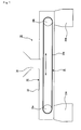
- Fig. 1 is a cross-sectional view that schematically shows one example of the transporting apparatus of the present invention.
- This transporting apparatus 30 is constituted by storage units 31A and 31B used for temporarily storing a wet mixture, a casing 33 having a supplying port 34 through which the wet mixture is charged, and a transporting unit 32 that is constituted by a belt conveyor 35 and is used for transporting the wet mixture.
- a wet mixture prepared in a wet mixing machine (not shown)
- the supplied wet mixture is accumulated on the belt conveyor 35 that constitutes the transporting unit 32.
- the belt conveyor 35 which is constituted by a conveyor belt 35a and rollers 36a and 36b, transports a wet mixture (not shown) accumulated on the belt conveyor 35, toward the storage unit 31A continuously or intermittently, and charges the mixture into the storage unit 31A.
- the storage unit 31A has a discharging port that can be opened and closed at its bottom face, and the storage unit 31A can temporarily store a fixed amount of the wet mixture, and can also charge the wet mixture, while controlling the amount thereof to a fixed amount per unit time, through the discharging port into the next process, for example, a process for manufacturing a molded body by using an extrusion-molding machine.
- the wet mixture accumulated on the belt conveyor 35 can be transported to the storage unit 31B continuously or intermittently so that the wet mixture can be charged into the storage unit 31B.
- the storage unit 31B which also has a discharging port that can be opened and closed at its bottom face, temporarily stores a fixed amount of the wet mixture, and also charges the wet mixture into the next process, while controlling the amount of the wet mixture to a fixed amount per unit time. Accordingly, in the transporting apparatus 30, the transporting unit is provided with a distributing mechanism.
- the amount to be respectively delivered can be selected by adjusting the speed of the belt conveyor or the respective driving time period or the like of the forward and reverse rotations.
- the selection can be made on demand.
- the wet mixing machine (not shown) in the process prior to the transporting apparatus 30 is allowed to carry out the mixing, and the wet mixture is continuously charged into the transporting apparatus 30; thus, even in the case where the operation of any process in the next process and thereafter is stopped, the state as it is can be maintained if only for a short period of time.
- the wet mixture can be continuously supplied to the extrusion-molding machine.
- the wet mixture can be temporarily stored in the storage units 31A and 31B.
- the transporting apparatus 30 is provided with a casing 33 having a lid, which covers the entire periphery of the belt conveyor 35 so as to produce a tightly sealed state in which the storage units 31A and 31B are included.
- the transporting unit is not necessarily required to have a casing; however, from the viewpoint of quality maintenance of the wet mixture, the transporting unit is desirably provided with a casing, and in particular, from the viewpoint of achieving the above-mentioned effects, it is more desirably provided with a casing having a lid. Therefore, as shown in Fig.
- the transporting unit desirably comprises a casing and a belt conveyor placed inside the casing.
- the casing having a lid of course includes a casing constituted by a box-shaped member having a lid, as well as a casing that has been preliminarily formed into a tube shape.
- the moisture content of the wet mixture is desirably controlled so that the moisture content variation of the wet mixture is set to 1% by weight or less, and by using the casing with a lid, the moisture content can be controlled in this manner.
- This arrangement is desirable, because the rate of occurrence of defective products in the post process becomes smaller as the moisture content variation of the wet mixture is reduced.
- the transporting apparatus 30 shown in Fig. 1 is a transporting apparatus provided with a distribution mechanism, and the distribution mechanism is installed in the transporting unit.
- the structure of the transporting apparatus of the present invention is not intended to be limited by this structure, and may have, for example, the following structure.
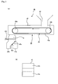
- Fig. 2(a) is a cross-sectional view that schematically shows another example of the transporting apparatus of the present invention
- Fig. 2 (b) is a bottom face view of a storage unit that constitutes the transporting apparatus shown in Fig. 2 (a).
- a transporting apparatus 40 shown in Fig. 2 is a transporting apparatus provided with a distribution mechanism, and in this transporting apparatus 40, the distributionmechanism is installed in a storage unit 41, as is different from the transporting apparatus 30 shown in Fig. 1.
- the transporting apparatus 40 comprises the storage unit 41 used for temporarily storing the wet mixture, and a transporting unit 42 which transports the wet mixture, including a casing 43 having a supplying port 44 through which the wet mixture is charged and a belt conveyor 45.
- the wet mixture prepared in the wet mixing machine (not shown) is charged into the transporting unit 42 through the supplying port 44, the wet mixture is accumulated on the belt conveyor 45 that constitutes the transporting unit 42.
- the belt conveyor 45 which is constituted by a conveyor belt 45a and rollers 46a and 46b, transports the wet mixture accumulated on the belt conveyor 45 toward the storage unit 41 continuously or intermittently, and charges the wet mixture into the storage unit 41.
- the storage unit 41 can temporarily store a fixed amount of the wet mixture, and can also charge the wet mixture into the next process, while controlling the amount thereof to a fixed amount per unit time.
- the storage unit 41 is provided with a closing plate 47b capable of sliding laterally, and when this closing plate 47b is closed (state shown in Fig. 2), the inner space of the storage unit 41 can be divided into the upper and the lower parts.
- the lower part separated by the closing plate 47b of the storage unit 41 is provided with two discharging ports 41a and 41b on its bottom face, and a distribution mechanism, which allows only either one of the discharging ports to discharge the wet mixture, is installed therein.
- a shaft member 47c is rotatably attached to a branch portion between the discharging port 41a side and the discharging port 41b side, and one side of a plate-shaped switching plate 47a is secured to the shaft member 47c so that the switching plate 47a can be shifted at a predetermined angle in association with the rotation of the shaft member 47c.
- the wet mixture transported from the transporting unit 42, can be stored in the storage unit 41. Moreover, in the case where the closing plate 47b is pulled out to be in an open state, the wet mixture can be transported to an apparatus used in the next process through the discharging port.
- the switching plate 47a at such a position (see Fig. 2) as to plug the discharging port 41a side, the wet mixture stored on the closing plate 47b can be transported to an apparatus used in the next process through the discharging port 41b.
- the stored wet mixture can be transported to an apparatus used in the next process through the discharging port 41a. Therefore, in the storage unit 41, by closing the closing plate, the wet mixture can be temporarily stored, and by selecting which discharging port to be opened (closed) using the switching plate, the wet mixture can be distributed and transported to an apparatus used in the next process.
- the switching plate 47a may be placed at a position that covers neither of the discharging ports so that the wet mixture may be simultaneously transported to an apparatus used in the next process through both of the discharging ports 41a and 41b.
- a charging port of an extrusion-molding machine to be used in the next process is placed right below the discharging port 41a or 41b.
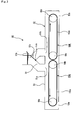
- FIG. 3 is a cross-sectional view that schematically shows still another example of the transporting apparatus of the present invention.
- a transporting apparatus 50 shown in Fig. 3 is a transporting apparatus provided with a transporting unit and a storage unit; however, this transporting apparatus 50 is different from the transporting apparatus 30 shown in Fig. 1 in that the storage unit is placed on the upper stream side from the transporting unit in the transporting path of the wet mixture.
- the transporting apparatus 50 comprises a storage unit 51 used for temporarily storing the wet mixture, and a transporting unit 52 for transporting the wet mixture, which is constituted by a casing 53 and belt conveyors 55A and 55B, and a charging port formed on the upper face of the casing 53 is used for charging the wet mixture into the casing 53, is allowed to communicate with discharging ports 51a and 51b formed on the lower face of the storage unit 51.
- the storage unit 51 is provided with a closing plate 57b capable of sliding laterally, and when this closing plate 57b is closed (state shown in Fig. 3), the inner space of the storage unit 51 can be divided into the upper and the lower parts.
- the lower section separated by the closing plate 57b of the storage unit 51 is provided with two discharging ports 51a and 51b on its bottom face, and a distribution mechanism, which allows only either one of the discharging ports to discharge the wet mixture, is installed therein.
- a shaft member 57c is rotatably attached to a branch portion between the discharging port 51a side and the discharging port 51b side, and one side of a plate-shaped switching plate 57a is secured to the shaft member 57c so that the switching plate 57a can be shifted to a predetermined angle in association with the rotation of the shaft member 57c.
- a belt conveyor 55A including a conveyor belt 155a and rollers 56a and 56b, and a belt conveyor 55B including a conveyor belt 155b and rollers 56c and 56d, are placed inside the casing 53, and the respective belt conveyors are designed to transport the wet mixture toward the end sides of the casing 53.
- the wet mixture prepared in the wet mixing machine (not shown), is charged into the storage unit 51, and the wet mixture is stored on the closing plate 57b, if necessary, and then charged into the casing 53 through the opened discharging port to be accumulated on the belt conveyor.
- the discharging port 51a of the storage unit 51 is open, the wet mixture is accumulated on the conveyor belt 155a, while, in the case where the discharging port 51b is open, the wet mixture is accumulated on the conveyor belt 155b.
- the mechanism used for storing the wet mixture in the storage unit 51 and the mechanism used for discharging either of the wet mixtures through the discharging port are the same as those mechanisms provided in the storage unit 41 shown in Fig. 2. Therefore, the transporting apparatus 50 can temporarily store the wet mixture on the upstream side of the transporting unit. Moreover, in the transporting apparatus 50, the storage unit 51 is provided with a distribution mechanism.
- the transporting apparatus of the present invention may have a storage unit on the upper stream side of the transporting unit.
- Each of the transporting apparatuses that have been explained by reference to Figs. 1 to 3 is a transporting apparatus equipped with a storage unit on either the upstream side or the downstream side of the transporting unit; however, it is only necessary for the transporting apparatus of the present invention to include at least one transporting unit and one storage unit, and for example, storage units may be installed on both of the upstream side and the downstream side of the transporting unit.
- either the storage unit or the transporting unit is provided with a distribution mechanism; however, in the transporting apparatus of the present invention, both of the units may have distribution mechanisms.
- the distribution ends are not limited to two places, and may be prepared as two or more places.
- a belt conveyor using a flat belt is installed as the conveyor belt; however, the conveyor to be used in the transporting apparatus of the present invention is not limited thereto, and may be, for example, conveyors as shown in Figs. 4-1 and 4-2.
- Each of Figs. 4-1(a) and 4-2(a) is a plan view that schematically shows another example of a conveyor constituting the transporting apparatus of the present invention, and each of Figs. 4-1(b) and 4-2(b) is a cross-sectional view of each of Figs. 4-1(a) and 4-2 (a) .
- 4-1 (a) and 4-1 (b) is equipped with a conveyor belt 65a with a bridge and rollers 66a and 66b, and the conveyor belt 65a with a bridge has a plate-shaped protruding member 65b that is placed virtually perpendicularly to the advancing direction of the belt.
- the transporting unit constituted by the conveyor 65 may be of course equipped with a casing.
- a conveyor 75 shown in Figs. 4-2 (a) and 4-2 (b), is a chain conveyor with buckets, which is equipped with a chain with buckets 75a and rollers 76a and 76b, and a bucket 75b used for holding the wet mixture is secured on the surface of the chain with buckets 75a with predetermined intervals.
- the transporting unit constituted by the conveyor 75, may of course have a casing.
- the conveyors, shown in Figs. 4-1 and 4-2 may also be desirably used as the transporting unit constituting the transporting apparatus of the present invention.
- the transporting apparatus of the present invention may use, for example, a chain conveyor, a pallet conveyor, a trolley conveyor, a flow conveyor, a flight conveyor, a disc conveyor, a power screw, a screw conveyor and the like as a conveyor constituting the transporting unit.
- the method for manufacturing a honeycomb structured body of the present invention comprises: carrying out a transporting process in which a wet mixture containing inorganic powders that have been wet-mixed is transported to an apparatus used in an extrusion-molding process, followed by manufacturing a pillar-shaped honeycomb molded body having a number of cells longitudinally placed in parallel with one another with a cell wall therebetween through extrusion molding, and firing the honeycomb molded body to manufacture a honeycomb structured body comprising a honeycomb fired body.
- a transporting apparatus which comprises a storage unit for temporarily storing the wet mixture and a transporting unit equipped with a conveyor for transporting the wet mixture, is utilized in the transporting process so that the wet mixture is transported to an extrusion-molding machine.
- the following description will discuss the method for manufacturing the honeycomb structured body of the present invention in the order of processes.
- the following description will discuss a method for manufacturing a honeycomb structured body by using silicon carbide powders as inorganic powders, with reference to an example of a method for manufacturing a honeycomb structured body which is mainly composed of silicon carbide as constituent material.
- the main component of the constituent materials for the honeycomb structured body is not limited to silicon carbide, and other examples thereof include: nitride ceramic materials, such as aluminum nitride, silicon nitride, boron nitride and titanium nitride, carbide ceramic materials, such as zirconium carbide, titanium carbide, tantalum carbide and tungsten carbide, and oxide ceramic materials, such as alumina, zirconia, cordierite, mullite, and aluminum titanate.
- non-oxide ceramic materials are desirably used, and in particular, silicon carbide is more desirably used. Silicon carbide is desirable because of its superior heat resistant characteristics, mechanical strength, thermal conductivity and the like.
- materials such as a silicon-containing ceramic material manufactured by blending metal silicon in the above-mentioned ceramic material and a ceramic material that is combined by silicon or a silicate compound, may also be used as the constituent materials, and among these, a material manufactured by blending silicon carbide with metal silicon (silicon-containing silicon carbide) is desirably used.
- inorganic powders such as silicon carbide powders having different average particle sizes, and an organic binder are dry-mixed to prepare a mixed powder, and a liquid-state plasticizer, a lubricant and water are mixed to prepare a mixed liquid, and the mixed powder and the mixed liquid are mixed by using a wet-mixing device so that a wet mixture for use in manufacturing a molded body is prepared.
- the particle size of the silicon carbide powder although not particularly limited, those which are less susceptible to shrinkage in the succeeding firing process are desirably used, and for example, a mixed powder, prepared by combining 100 parts by weight of powder having an average particle size of 0.3 to 50 ⁇ m with 5 to 65 parts by weight of powder having an average particle size of 0.1 to 1.0 ⁇ m, is desirably used.
- a mixed powder prepared by combining 100 parts by weight of powder having an average particle size of 0.3 to 50 ⁇ m with 5 to 65 parts by weight of powder having an average particle size of 0.1 to 1.0 ⁇ m.
- the firing temperature it is necessary to adjust the firing temperature, and the pore diameter can be adjusted by adjusting the particle size of the inorganic powder.
- the binder although not particularly limited, examples thereof include: methylcellulose, carboxy methylcellulose, hydroxy ethylcellulose, polyethylene glycol and the like. Among these, methylcellulose is more desirably used.
- the compounding amount of the above-mentioned binder is desirably set to 1 to 10 parts by weight with respect to 100 parts by weight of the silicon carbide powder.
- plasticizer although not particularly limited, for example, glycerin and the like may be used.
- lubricant although not particularly limited, for example, polyoxy alkylene-based compounds, such as polyoxyethylene alkyl ether and polyoxy propylene alkyl ether, may be used. Specific examples of the lubricant include: polyoxyethylene monobutyl ether and polyoxypropylene monobutyl ether.
- the plasticizer and the lubricant are not necessarily contained in the mixed material powder depending on cases.
- a dispersant solution may be used, and with respect to the dispersant solution, examples thereof include: water, an organic solvent such as benzene, and an alcohol such as methanol.
- a molding auxiliary may be added to the wet mixture.
- examples thereof include: ethylene glycol, dextrin, fatty acid, fatty acid soap, polyalcohol and the like.
- balloons that are fine hollow spheres comprising oxide-based ceramics and a pore forming agent such as spherical acrylic particles or graphite may be added to the above-mentioned material paste, if necessary.
- alumina balloons glass micro-balloons, shirasu balloons, fly ash balloons (FA balloons), mullite balloons and the like may be used.
- alumina balloons are more desirably used.
- the temperature thereof is desirably set to 28°C or less.
- the organic binder tends to be gelatinized.
- the rate of organic components in the wet mixture is desirably set to 10% by weight or less, and the content of moisture is desirably set from 8.0 to 20.0% by weight.
- the wet mixture, which has been prepared, is then transported, and charged into a molding machine.
- the transporting process of the wet mixture is carried out by a transporting apparatus that is equipped with a storage unit used for temporarily storing the wet mixture and a transporting unit for transporting the wet mixture. More specifically, the transporting apparatus of the present invention that has been explained earlier can be used.
- the prepared wet mixture is properly transported to an extrusion-molding machine in the succeeding process, and even when any trouble occurs in the next process and thereafter, which will be described later, causing the stoppage of the manufacturing line, the wet mixture can be temporality stored in the storage unit so that the preceding process of preparing the wet mixture can be operated without stopping.
- the storage unit is desirably designed to be able to store the wet mixture in the amount of 1.5 to 3 times (weight conversion) higher than the molding capability of the extrusion-molding machine.
- the method for manufacturing the present invention upon transporting the prepared wet mixture, it is desirable to store the wet mixture in the storage unit for a fixed period of time. This is desirable, because the moldability of the wet mixture is improved in the succeeding extrusion-molding process. Although the reason for this has not been clarified, it is presumed that, since the wet mixture is refrigerated and aged, the organic binder is allowed to swell during these refrigerating and aging time so that the lubrication characteristics of the inorganic particles (silicon carbide particles) is improved.
- the storing time is not particularly limited, the lower limit of the storing time is desirably set to one hour, more desirably 4 hours, and the upper limit is desirably set to 10 hours, more desirably 8 hours.
- the storing time of less than one hour the moldability of the wet mixture is hardly improved; in contrast, in the case of the storing time exceeding 10 hours, the wet mixture tends to be partially dried to sometimes cause degradation in the moldability.
- the molding pressure can be reduced at the time of extrusion molding, and by reducing the molding pressure, the rate of occurrence of defective molded products can be reduced, and in addition, the life of wear parts (metal die and the like) constituting the extrusion-molding machine can be prolonged.
- the wet mixture transported by the transporting apparatus After the wet mixture transported by the transporting apparatus has been charged into the extrusion-molding machine, it is extrusion-molded into a pillar-shaped honeycomb molded body having a number of cells longitudinally placed in parallel with one another with a cell wall therebetween.
- the shape indicated by the word "pillar” refers to any desired shape of a pillar including a round pillar, an oval pillar, a polygonal pillar and the like.
- the resulting honeycomb molded body is dried by using a dryer, such as a microwave dryer, a hot-air dryer, a dielectric dryer, a reduced-pressure dryer, a vacuum dryer and a freeze dryer.
- ends on the outlet side of a group of cells on the inlet side and ends on the inlet side of a group of cells on the outlet side are filled with a predetermined amount of plug material paste that is to form plugs so as to seal those cells.
- plug material paste although not particularly limited, those plug material pastes that allow the plugs formed through post processes to have a porosity in a range from 30 to 75% are desirably used, and, for example, the same material as that of the wet mixture may be used.
- a degreasing process for example, at a temperature from 200 to 500°C
- a firing process for example, at a temperature from 1400 to 2300°C
- honeycomb fired body in which a plurality of cells are longitudinally placed in parallel with one another with a cell wall therebetween, and either one of ends of the cells is sealed.
- the conditions for degreasing and firing the honeycomb molded body conventional conditions that have been used upon manufacturing a filter comprising a porous ceramic material may be adopted.
- a sealing material paste to form a sealing material layer is applied onto a side face of the honeycomb fired body with an even thickness to form a sealing material paste layer, and a process of laminating another honeycomb fired body on the sealing material paste layer is successively repeated so that an aggregate body of honeycomb fired bodies having a predetermined size is manufactured.
- sealing material paste for example, those comprising inorganic fibers and/or inorganic particles in addition to an inorganic binder and an organic binder may be used.
- inorganic binder for example, silica sol, alumina sol and the like may be used. Each of these may be used alone or two or more kinds of these may be used in combination.
- silica sol is more desirably used.
- organic binder examples thereof include polyvinyl alcohol, methyl cellulose, ethyl cellulose, carboxymethyl cellulose, and the like. Each of these may be used alone or two or more kinds of these may be used in combination. Among the organic binders, carboxymethyl cellulose is more desirably used.
- examples thereof include ceramic fibers, such as silica-alumina, mullite, alumina and silica, and the like. Each of these may be used alone or two or more kinds of these may be used in combination.
- alumina fibers are more desirably used.
- examples thereof include carbides and nitrides, and specific examples include inorganic powder comprising silicon carbide, silicon nitride and boron nitride, and the like. Each of these may be used alone, or two or more kinds of these may be used in combination.
- silicon carbide having superior thermal conductivity is desirably used.
- balloons that are fine hollow spheres comprising oxide-based ceramics and a pore forming agent such as spherical acrylic particles or graphite may be added to the above-mentioned sealing material paste, if necessary.
- examples thereof include alumina balloons, glass micro-balloons, shirasu balloons, fly ash balloons (FA balloons) and mullite balloons may be used.
- alumina balloons are more desirably used.
- This aggregate body of honeycomb fired bodies is heated so that the sealing material paste layers are dried and solidified to form sealing material layers (adhesive layers).
- a cutting process by using a diamond cutter or the like is carried out on the aggregate body of honeycomb fired bodies in which a plurality of honeycomb fired bodies are bonded to one another by interposing a sealing material layer (adhesive layers) so that a cylindrical-shaped ceramic block is manufactured.
- a sealing material layer is formed on the outer circumference of the ceramic block by using the above-mentioned sealing material paste so that a honeycomb structured body, in which a plurality of honeycomb fired bodies are bound to one another by interposing a sealing material layer (adhesive layers), with a sealing material layer (coat layer) being formed on the outer circumference of a cylindrical-shaped ceramic, can be manufactured.
- a catalyst is supported on the honeycomb structured body on demand.
- the supporting process of the catalyst may be carried out on the honeycomb structural bodies prior to being manufactured into an aggregate body.
- an alumina film having a high specific surface area is formed on the surface of the honeycomb structured body, and a co-catalyst and a catalyst such as platinum are applied to the surface of this alumina film.
- Examples of the method for forming the alumina film on the surface of the honeycomb structured body include a method in which the honeycomb structured body is impregnated with a solution of a metal compound containing aluminum such as Al (NO 3 ) 3 and then heated, and a method in which the honeycomb structured body is impregnated with a solution containing alumina powder and then heated, and the like.
- a method for applying a co-catalyst to the alumina film for example, a method in which the honeycomb structured body is impregnated with a solution of a metal compound containing a rare-earth element, such as Ce (NO 3 ) 3 , and then heated is proposed.
- Examples of the method for applying a catalyst to the alumina film include: a method in which the ceramic fired body is impregnated with a nitric acid solution of diamine dinitro platinum ([Pt(NH 3 ) 2 (NO 2 ) 2 ]HNO 3 : 4.53% by weight in platinum concentration) or the like and then heated, and the like.
- the catalyst may be applied in such a manner that a catalyst is preliminarily applied to alumina particles and the honeycomb structured body is impregnated with a solution containing the alumina powder to which the catalyst has been applied, and then heated.
- honeycomb structured body (hereinafter, referred to as aggregated honeycomb structured body) having a structure in which a plurality of honeycomb fired bodies are bonded to one another by interposing a sealing material layer (adhesive layer); however, the honeycomb structured body to be manufactured by the method for manufacturing the present invention may be a honeycomb structured body in which a cylindrical-shaped ceramic block is constituted by a single honeycomb fired body (hereinafter, referred to as integral honeycomb structured body).
- a honeycomb molded body is manufactured by using the same method as that used for manufacturing the aggregated honeycomb structured body, except that the size of the honeycomb molded body to be formed through extrusion-molding is larger in comparison with that of the aggregated honeycomb structured body.
- the method for transporting, storing and the like of the wet mixture prior to the molding process are the same as those methods used for the aggregated honeycomb structured body; therefore, the description thereof will be omitted.
- the honeycomb molded body is dried by using a dryer, such as a microwave dryer, a hot-air dryer, a dielectric dryer, a reduced-pressure dryer, a vacuum dryer and a freeze dryer to form a ceramic dried body.
- a dryer such as a microwave dryer, a hot-air dryer, a dielectric dryer, a reduced-pressure dryer, a vacuum dryer and a freeze dryer to form a ceramic dried body.
- the degreasing and firing processes are carried out to manufacture a ceramic block, and by forming a sealing material layer (coat layer), if necessary, an integral honeycomb structured body can be manufactured.
- a catalyst may be supported on the integral honeycomb structured body by using the same method.
- a sequence of manufacturing processes may be carried out through a single production line; however, for example, the processes up to the process of charging the wet mixture by using a transporting apparatus equipped with a distribution mechanism may be carried out through a single production line, and the process of manufacturing a molded body by using an extrusion-molding machine and processes thereafter may be carried out through two or more production lines.
- the distribution mechanism placed in the transporting apparatus, is allowed to distribute and supply the wet mixture timely to the respective production lines.
- a method for manufacturing a honeycomb structured body in which either one of the ends of each cell is sealed so that it can be used as a honeycomb filter and a transporting apparatus usable in this manufacturing method.
- the transporting apparatus and the method for manufacturing a honeycomb structured body can be preferably used for the manufacture of a honeycomb structured body which can be used as a catalyst supporting carrier, i.e., a honeycomb structured body in which ends of cells are not sealed.
- the method for manufacturing a honeycomb structured body using the transporting apparatus of the present invention in the case where a wet mixture had been stored in the transporting apparatus for a fixed period of time, and then a molded body of a predetermined shape was manufactured by using an extrusion-molding machine, the relationship between the storing period of time in the transporting apparatus (storage unit) and the molding pressure (MPa) was evaluated.
- the molding rate was set to 4000 mm/min, and the molding pressure was adjusted so that the honeycomb molded body could be formed at this molding rate.
- Powder of ⁇ -type silicon carbide having an average particle size of 10 ⁇ m (250 kg), powder of ⁇ -type silicon carbide having an average particle size of 0.5 ⁇ m (100 kg) and an organic binder (methylcellulose) (20 kg) were mixed to prepare a mixed powder.
- a lubricant (UNILUB, made by NOF Corp.) (12 kg), a plasticizer (glycerin) (5 kg) and water (65 kg) were mixed to prepare a liquid mixture, and this liquid mixture and the mixed powder were mixed by using a wet mixer to prepare a wet mixture.
- the moisture content of the wet mixture thus prepared was 14% by weight.
- this wet mixture was transported to an extrusion-molding machine by using the transporting apparatus of the present invention shown in Fig. 1.
- the transporting apparatus shown in Fig. 1 was equipped with a distribution mechanism, the distribution mechanism was not used in this example, and the wet mixture, charged through a charging port 34, was transported to a storage unit 31A via a belt conveyor. Thereafter, the wet mixture was stored in the storage unit 31A for one hour, and this was then charged into a material charging port of the extrusion-molding machine placed right under the storage unit 31A.
- the moisture content of the wet mixture immediately before the charging into the extrusion-molding machine was 13.5% by weight.
- the wet mixture was then extrusion-molded into a molded body having a shape shown in Fig. 6.
- the molding pressure in this example was 9.0 MPa.
- a honeycomb fired body comprising a silicon carbide sintered body with a porosity of 42%, an average pore diameter of 12.5 ⁇ m, a size of 34.3 mm 34.3 mm ⁇ 150 mm, the number of cells (cell density) of 46.5/cm 2 and a thickness of each cell wall of 0.20 mm.
- a heat resistant sealing material paste containing 30% by weight of alumina fibers having an average fiber length of 20 ⁇ m, 21% by weight of silicon carbide particles having an average particle size of 0.6 ⁇ m, 15% by weight of silica sol, 5.6% by weight of carboxymethyl cellulose and 28.4% by weight of water, a large number of the honeycomb fired bodies were bonded to one another, and then dried at 120°C and cut by using a diamond cutter to manufacture a cylindrical-shaped ceramic block with a sealing material layer (adhesive layer) having a thickness of 1 mm.
- a sealing material layer adheresive layer
- silica-alumina fibers (average fiber length: 100 ⁇ m, average fiber diameter: 10 ⁇ m) (23.3% by weight) serving as inorganic fibers, silicon carbide powder having an average particle size of 0.3 ⁇ m (30.2% by weight) serving as inorganic particles, silica sol (content of SiO 2 in sol: 30% by weight) (7% by weight) serving as an inorganic binder, carboxymethyl cellulose (0.5% by weight) serving as an organic binder and water (39% by weight) were mixed, and kneaded to prepare a sealing material paste.
- a sealing material paste layer having a thickness of 0.2 mm was formed on the outer circumference of the ceramic block.
- This sealing material paste layer was then dried at 120°C so that a honeycomb structured body 10 having a cylindrical shape (143.8 mm in diameter ⁇ 150 mm in length) with a sealing material layer (coat layer) formed on the outer circumference was manufactured.
- Example 2 By using the same method as Example 1 except that the storing time in the transporting apparatus (storage unit) was set to the period of time shown in Table 1, a honeycomb structured body was manufactured. In each of the examples, each of molding pressures (MPa) also shown in Table 1 was required upon extrusion molding.
- MPa molding pressures
- Example 2 By using the same method as Example 1 except that the storing time in the transporting apparatus (storage unit) was set to the period of time shown in Table 1, a honeycomb structured body was manufactured. In each of the Reference Examples, each of molding pressures (MPa) also shown in Table 1 was required upon extrusion molding.
- MPa molding pressures
- Example 1 Storing time (hr) Molding pressure (MPa) Example 1 1 9.0 Example 2 4 6.0 Example 3 8 7.0 Example 4 10 8.5 Reference Example 1 0 10.0 Reference Example 2 12 11.0
- Fig. 1 is a cross-sectional view that schematically shows one example of a transporting apparatus in accordance with the present invention.
- Fig. 2(a) is a cross-sectional view that schematically shows another example of the transporting apparatus in accordance with the present invention; and
- Fig. 2 (b) is a bottom face view of a storage unit constituting the transporting apparatus shown in Fig. 2(a).
- Fig. 3 is a cross-sectional view that schematically shows another example of the transporting apparatus of the present invention.
- Fig. 4-1 (a) is a plan view that schematically shows one example of a conveyor which forms one component of the transporting apparatus of the present invention, and
- Fig. 4-1 (b) is a cross-sectional view of Fig. 4-1(a).
- Fig. 4-2 (a) is a plan view that schematically shows another example of the conveyor constituting the transporting apparatus of the present invention
- Fig. 4-2 (b) is a cross-sectional view of Fig. 4-2 (a)
- Fig. 5 is a perspective view that schematically shows one example of a ceramic filter
- Fig. 6 (a) is a perspective view that schematically shows a honeycomb fired body constituting the ceramic filter shown in Fig. 5
- Fig. 6(b) is a cross-sectional view taken along line A-A of Fig. 6(a).
Landscapes
- Engineering & Computer Science (AREA)
- Mechanical Engineering (AREA)
- Manufacturing & Machinery (AREA)
- Chemical & Material Sciences (AREA)
- Ceramic Engineering (AREA)
- Devices For Post-Treatments, Processing, Supply, Discharge, And Other Processes (AREA)
Abstract
Description
- The present invention relates to a transporting apparatus and a method for manufacturing a honeycomb structured body.
- In recent years, particulates such as soot contained in exhaust gases that are discharged from internal combustion engines of vehicles, such as buses and trucks, and construction machines, have raised serious problems as contaminants harmful to the environment and the human body.
For this reason, various honeycomb filters using honeycomb structural bodies comprising porous ceramics, which serve as filters that capture particulates in exhaust gases to purify the exhaust gases, have been proposed. - Fig. 5 is a perspective view that schematically shows one example of a ceramic filter of this kind, Fig. 6 (a) is a perspective view that schematically shows a honeycomb fired body constituting the ceramic filter, and Fig. 6 (b) is a cross-sectional view taken along line A-A of Fig. 6(a).
- In a
ceramic filter 130, a plurality of honeycomb firedbodies 140 shown in Fig. 6 are bonded to one another by interposing a sealing material layer (adhesive layers) 131 to form aceramic block 133, and a sealing material layer (coat layer) 132 is further formed on the outer circumference of thisceramic block 133.
Moreover, as shown in Fig. 6, a honeycomb firedbody 140 has a number ofcells 141 longitudinally placed in parallel with one another, so that eachcell wall 143 that separates thecells 141 is allowed to function as a filter. - In other words, as shown in Fig. 6(b), each of the
cells 141, formed in the honeycomb firedbody 140, is sealed with aplug material layer 142 at either one of ends on its exhaust-gas inlet side and outlet side so that exhaust gases that have entered onecell 141 are discharged from anothercell 141 after having surely passed through eachcell wall 143 that separates thecells 141; thus, when exhaust gases pass through thecell wall 143, particulates are captured by thecell wall 143 so that the exhaust gases are purified. - Conventionally, upon manufacturing such a
ceramic filter 130, first, a ceramic powder, a binder, a dispersant solution and the like are mixed to prepare a wet mixture. Then, the wet mixture is continuously extrusion-molded through a die, and the extruded molded body is cut into a predetermined length so that a rectangular pillar-shaped honeycomb molded body is manufactured. - Next, the resulting honeycomb molded body is dried by utilizing a microwave dryer or a hot-air dryer, and after predetermined cells have been sealed so that either one of ends of each cell is sealed by the plug material layer, a degreasing process and a firing process are carried out on the resulting honeycomb molded body to manufacture a honeycomb fired body.
- Thereafter, a sealing material paste is applied to the side faces of the honeycomb fired body, and the honeycomb fired bodies are mutually bonded so that an aggregate body of the honeycomb fired bodies, in which a number of the honeycomb fired bodies are bound to one another by interposing the sealing material layer (adhesive layers), is manufactured. Next, the resulting aggregate body of the honeycomb fired bodies is cut and machined into a predetermined shape, such as a cylindrical shape and a cylindroid shape, by using a cutting tool or the like so that a ceramic block is formed, and lastly, a sealing material paste is applied onto the periphery of the ceramic block to form a sealing material layer (coat layer); thus, the manufacturing process for the ceramic filter is completed.
- In the manufacturing method of this kind, after a wet mixture has been prepared, it is necessary to transport the wet mixture to an extrusion-molding machine at the next process through a transporting apparatus.
Examples of the transporting apparatus used for transporting the wet mixture include, for example, those disclosed in Patent Documents 1 and 2. -
- Patent Document 1:
JP-A 2002-255353 - Patent Document 2:
JP-A 5-131432 - However, the main purpose of the conventional transporting apparatus is only to continuously supply a material mixture; therefore, in the case where the succeeding process after transporting the material mixture by the transporting apparatus is stopped due to any trouble, since the supply of the material needs to be stopped, the transporting apparatus also needs to be stopped, and in addition, the preceding processes before the transporting apparatus, that is, the process of preparing the material mixture and the like, also need to be stopped; consequently, following the stoppage of one process, all the processes need to be stopped, resulting in degradation in the operation efficiency.
Moreover, in the case where the supply of the wet mixture to the transporting apparatus is once stopped, immediately after resuming the operation of the extrusion-molding machine again, the molding machine sometimes has an insufficient supply of the wet mixture and, in such a case, the extruded molded body may become a defective product. - In order to solve the above-mentionedproblems, the present inventors have intensively studied, and have devised a transporting apparatus in which, even in the event of any trouble in the succeeding processes after the transporting process of a wet mixture, it is not necessary to stop the operation in the preceding process before the transportation of the wet mixture so that the shortage of the wet mixture in the molding machine can be prevented, and a method for manufacturing a honeycomb structured body using such a transporting apparatus.
- In other words, the transporting apparatus of the present invention comprises a storage unit for temporarily storing a wet mixture and a transporting unit equipped with a conveyor for transporting the wet mixture.
- Desirably, the transporting apparatus further comprises a distribution mechanism for distributing the wet mixture to different transporting ends, and the distribution mechanism is desirably installed in the storage unit and/or the transporting unit.
Moreover, the transporting unit is desirably constituted by a casing and a belt conveyor installed in the casing. - A method for manufacturing a honeycomb structured body in accordance with the present invention comprises: carrying out a transporting process in which a wet mixture containing inorganic powders that have been wet-mixed is transported to an apparatus used in an extrusion-molding process, followed by manufacturing a pillar-shaped honeycomb molded body having a number of cells longitudinally placed in parallel with one another with a cell wall therebetween through extrusion molding, and firing the honeycomb molded body to manufacture a honeycomb structured body comprising a honeycomb fired body. In this method, a transporting apparatus, which comprises a storage unit for temporarily storing the wet mixture and a transporting unit equipped with a conveyor for transporting the wet mixture, is utilized in the transporting process so that the wet mixture is transported to an extrusion-molding machine.
- In the above-mentioned method for manufacturing a honeycomb structured body, the transporting apparatus desirably comprises a distribution mechanism for distributing the wet mixture to apparatuses used in different extrusion-molding processes, and the distribution mechanism is desirably installed in the storage unit and/or the transporting unit.
- In the above-mentioned method for manufacturing a honeycomb structured body, the transporting unit is desirably constituted by a casing and a belt conveyor installed in the casing.
- In the transporting apparatus of the present invention, even in the case where the operation is stopped due to any trouble or the like in a process after the transporting apparatus to cause a failure in continuously supplying the wet mixture, since a storage unit capable of temporarily storing the wet mixture is provided there, it is not necessary to stop processes before the transporting apparatus (process for preparing the wet mixture, and the like), and the processes are continuously operated so that it is possible to prevent degradation of the operation efficiency.
Moreover, since the transporting apparatus of the present invention is equipped with the storage unit, a required amount of the wet mixture can be always transported to an apparatus used in the succeeding process, and therefore, when the molding machine is stopped temporarily and then re-operated, a molded body having a desired shape can be immediately supplied to the succeeding process. - In the method for manufacturing a honeycomb structured body of the present invention, even in the case where the operation is stopped due to any trouble or the like in a process after the process of transporting the wet mixture, since a transporting apparatus equipped with a storage unit capable of temporarily storing the wet mixture is utilized as the transporting apparatus, it is not necessary to stop processes before the transporting apparatus (process for preparing the wet mixture, and the like) , and the processes can be continuously operated and therefore it is possible to prevent degradation of the operation efficiency.
Moreover, since the transporting apparatus is equipped with the storage unit, a required amount of the wet mixture can be always transported to an extrusion-molding machine in the succeeding process; therefore, when the extrusion-molding machine is stopped temporarily and then re-operated, a molded body having a desired shape can be immediately supplied. - First, the following description will discuss a transporting apparatus in accordance with the present invention.
The transporting apparatus of the present invention comprises a storage unit used for temporarily storing a wet mixture and a transporting unit equipped with a conveyor for transporting the wet mixture.
Fig. 1 is a cross-sectional view that schematically shows one example of the transporting apparatus of the present invention.
This transportingapparatus 30 is constituted bystorage units casing 33 having a supplyingport 34 through which the wet mixture is charged, and atransporting unit 32 that is constituted by abelt conveyor 35 and is used for transporting the wet mixture.
In the transportingapparatus 30, when a wet mixture, prepared in a wet mixing machine (not shown), is charged into the transportingunit 32 through the supplyingport 34, the supplied wet mixture is accumulated on thebelt conveyor 35 that constitutes thetransporting unit 32. - The
belt conveyor 35, which is constituted by aconveyor belt 35a androllers belt conveyor 35, toward thestorage unit 31A continuously or intermittently, and charges the mixture into thestorage unit 31A.
Thestorage unit 31A has a discharging port that can be opened and closed at its bottom face, and thestorage unit 31A can temporarily store a fixed amount of the wet mixture, and can also charge the wet mixture, while controlling the amount thereof to a fixed amount per unit time, through the discharging port into the next process, for example, a process for manufacturing a molded body by using an extrusion-molding machine. - Moreover, in the transporting
apparatus 30, by reversing the rotational direction of therollers belt conveyor 35 can be transported to thestorage unit 31B continuously or intermittently so that the wet mixture can be charged into thestorage unit 31B.
In the same manner as thestorage unit 31A, thestorage unit 31B, which also has a discharging port that can be opened and closed at its bottom face, temporarily stores a fixed amount of the wet mixture, and also charges the wet mixture into the next process, while controlling the amount of the wet mixture to a fixed amount per unit time.
Accordingly, in the transportingapparatus 30, the transporting unit is provided with a distributing mechanism.
Here, in the case where the transportingapparatus 30 supplies the wet mixture into two separate extrusion-molding machines, the amount to be respectively delivered can be selected by adjusting the speed of the belt conveyor or the respective driving time period or the like of the forward and reverse rotations. Here, as to what amount of the wet mixture is transported to which storage unit, the selection can be made on demand. - In this manner, in the transporting
apparatus 30, since thestorage units apparatus 30 is allowed to carry out the mixing, and the wet mixture is continuously charged into the transportingapparatus 30; thus, even in the case where the operation of any process in the next process and thereafter is stopped, the state as it is can be maintained if only for a short period of time.
In contrast, in the case where no wet mixture is charged into the transportingapparatus 30 due to a stoppage of the mixing operation in the wet mixing machine, so that the wet mixture needs to be supplied to the next process, also, the wet mixture can be continuously supplied to the extrusion-molding machine.
Moreover, in the transportingapparatus 30, the wet mixture can be temporarily stored in thestorage units - The transporting
apparatus 30 is provided with acasing 33 having a lid, which covers the entire periphery of thebelt conveyor 35 so as to produce a tightly sealed state in which thestorage units
Here, in the transporting apparatus of the present invention, the transporting unit is not necessarily required to have a casing; however, from the viewpoint of quality maintenance of the wet mixture, the transporting unit is desirably provided with a casing, and in particular, from the viewpoint of achieving the above-mentioned effects, it is more desirably provided with a casing having a lid.
Therefore, as shown in Fig. 1, the transporting unit desirably comprises a casing and a belt conveyor placed inside the casing.
Here, in the transporting apparatus of the present invention, the casing having a lid of course includes a casing constituted by a box-shaped member having a lid, as well as a casing that has been preliminarily formed into a tube shape. - Moreover, in the transporting
apparatus 30, the moisture content of the wet mixture is desirably controlled so that the moisture content variation of the wet mixture is set to 1% by weight or less, and by using the casing with a lid, the moisture content can be controlled in this manner. This arrangement is desirable, because the rate of occurrence of defective products in the post process becomes smaller as the moisture content variation of the wet mixture is reduced. - The
transporting apparatus 30 shown in Fig. 1 is a transporting apparatus provided with a distribution mechanism, and the distribution mechanism is installed in the transporting unit.
However, the structure of the transporting apparatus of the present invention is not intended to be limited by this structure, and may have, for example, the following structure.
Fig. 2(a) is a cross-sectional view that schematically shows another example of the transporting apparatus of the present invention, and Fig. 2 (b) is a bottom face view of a storage unit that constitutes the transporting apparatus shown in Fig. 2 (a). - A
transporting apparatus 40 shown in Fig. 2 is a transporting apparatus provided with a distribution mechanism, and in this transportingapparatus 40, the distributionmechanism is installed in astorage unit 41, as is different from the transportingapparatus 30 shown in Fig. 1. In other words, the transportingapparatus 40 comprises thestorage unit 41 used for temporarily storing the wet mixture, and atransporting unit 42 which transports the wet mixture, including acasing 43 having a supplyingport 44 through which the wet mixture is charged and abelt conveyor 45.
Here, when the wet mixture prepared in the wet mixing machine (not shown) is charged into the transportingunit 42 through the supplyingport 44, the wet mixture is accumulated on thebelt conveyor 45 that constitutes thetransporting unit 42. Thebelt conveyor 45, which is constituted by aconveyor belt 45a androllers belt conveyor 45 toward thestorage unit 41 continuously or intermittently, and charges the wet mixture into thestorage unit 41. Thestorage unit 41 can temporarily store a fixed amount of the wet mixture, and can also charge the wet mixture into the next process, while controlling the amount thereof to a fixed amount per unit time. - The
storage unit 41 is provided with aclosing plate 47b capable of sliding laterally, and when thisclosing plate 47b is closed (state shown in Fig. 2), the inner space of thestorage unit 41 can be divided into the upper and the lower parts.
Here, the lower part separated by theclosing plate 47b of thestorage unit 41 is provided with two dischargingports
In other words, ashaft member 47c is rotatably attached to a branch portion between the dischargingport 41a side and the dischargingport 41b side, and one side of a plate-shapedswitching plate 47a is secured to theshaft member 47c so that the switchingplate 47a can be shifted at a predetermined angle in association with the rotation of theshaft member 47c. - In the
storage unit 41 of this kind, when theclosing plate 47b is closed, the wet mixture, transported from the transportingunit 42, can be stored in thestorage unit 41.
Moreover, in the case where theclosing plate 47b is pulled out to be in an open state, the wet mixture can be transported to an apparatus used in the next process through the discharging port. Here, by placing theswitching plate 47a at such a position (see Fig. 2) as to plug the dischargingport 41a side, the wet mixture stored on theclosing plate 47b can be transported to an apparatus used in the next process through the dischargingport 41b. Moreover, in the case where the position of theswitching plate 47a is shifted to such a position as to plug the dischargingport 41b side, the stored wet mixture can be transported to an apparatus used in the next process through the dischargingport 41a.
Therefore, in thestorage unit 41, by closing the closing plate, the wet mixture can be temporarily stored, and by selecting which discharging port to be opened (closed) using the switching plate, the wet mixture can be distributed and transported to an apparatus used in the next process.
Here, in thestorage unit 41, the switchingplate 47a may be placed at a position that covers neither of the discharging ports so that the wet mixture may be simultaneously transported to an apparatus used in the next process through both of the dischargingports
Moreover, for example, a charging port of an extrusion-molding machine to be used in the next process is placed right below the dischargingport - Fig. 3 is a cross-sectional view that schematically shows still another example of the transporting apparatus of the present invention.
A transportingapparatus 50 shown in Fig. 3 is a transporting apparatus provided with a transporting unit and a storage unit; however, this transportingapparatus 50 is different from the transportingapparatus 30 shown in Fig. 1 in that the storage unit is placed on the upper stream side from the transporting unit in the transporting path of the wet mixture.
In other words, the transportingapparatus 50 comprises astorage unit 51 used for temporarily storing the wet mixture, and a transportingunit 52 for transporting the wet mixture, which is constituted by acasing 53 andbelt conveyors casing 53 is used for charging the wet mixture into thecasing 53, is allowed to communicate with dischargingports storage unit 51. - The
storage unit 51 is provided with aclosing plate 57b capable of sliding laterally, and when thisclosing plate 57b is closed (state shown in Fig. 3), the inner space of thestorage unit 51 can be divided into the upper and the lower parts.
Here, the lower section separated by theclosing plate 57b of thestorage unit 51 is provided with two dischargingports
In other words, ashaft member 57c is rotatably attached to a branch portion between the dischargingport 51a side and the dischargingport 51b side, and one side of a plate-shapedswitching plate 57a is secured to theshaft member 57c so that the switchingplate 57a can be shifted to a predetermined angle in association with the rotation of theshaft member 57c. - ' Moreover, a
belt conveyor 55A, including aconveyor belt 155a androllers belt conveyor 55B including aconveyor belt 155b androllers casing 53, and the respective belt conveyors are designed to transport the wet mixture toward the end sides of thecasing 53. - Here, in the transporting
apparatus 50, the wet mixture, prepared in the wet mixing machine (not shown), is charged into thestorage unit 51, and the wet mixture is stored on theclosing plate 57b, if necessary, and then charged into thecasing 53 through the opened discharging port to be accumulated on the belt conveyor. In other words, in the case where the dischargingport 51a of thestorage unit 51 is open, the wet mixture is accumulated on theconveyor belt 155a, while, in the case where the dischargingport 51b is open, the wet mixture is accumulated on theconveyor belt 155b.
Here, the mechanism used for storing the wet mixture in thestorage unit 51 and the mechanism used for discharging either of the wet mixtures through the discharging port, that is, the storing mechanism and the distribution mechanism possessed by thestorage unit 51, are the same as those mechanisms provided in thestorage unit 41 shown in Fig. 2.
Therefore, the transportingapparatus 50 can temporarily store the wet mixture on the upstream side of the transporting unit.
Moreover, in the transportingapparatus 50, thestorage unit 51 is provided with a distribution mechanism. - The wet mixtures, accumulated on the
respective conveyor belts ports casing 53.
In this manner, the transporting apparatus of the present invention may have a storage unit on the upper stream side of the transporting unit. - Each of the transporting apparatuses that have been explained by reference to Figs. 1 to 3 is a transporting apparatus equipped with a storage unit on either the upstream side or the downstream side of the transporting unit; however, it is only necessary for the transporting apparatus of the present invention to include at least one transporting unit and one storage unit, and for example, storage units may be installed on both of the upstream side and the downstream side of the transporting unit.
Moreover, in the transporting apparatuses that have been explained by reference to Figs. 1 to 3, either the storage unit or the transporting unit is provided with a distribution mechanism; however, in the transporting apparatus of the present invention, both of the units may have distribution mechanisms.
Moreover, in the case where the transporting apparatus of the present invention has a distribution mechanism, the distribution ends are not limited to two places, and may be prepared as two or more places. - Furthermore, in the transporting apparatuses that have been explained by reference to Figs. 1 to 3, a belt conveyor using a flat belt is installed as the conveyor belt; however, the conveyor to be used in the transporting apparatus of the present invention is not limited thereto, and may be, for example, conveyors as shown in Figs. 4-1 and 4-2.
Each of Figs. 4-1(a) and 4-2(a) is a plan view that schematically shows another example of a conveyor constituting the transporting apparatus of the present invention, and each of Figs. 4-1(b) and 4-2(b) is a cross-sectional view of each of Figs. 4-1(a) and 4-2 (a) .
Aconveyor 65, shown in Figs. 4-1 (a) and 4-1 (b) is equipped with aconveyor belt 65a with a bridge androllers conveyor belt 65a with a bridge has a plate-shaped protrudingmember 65b that is placed virtually perpendicularly to the advancing direction of the belt. Here, although not shown in the Figures, the transporting unit constituted by theconveyor 65 may be of course equipped with a casing. - Moreover, a
conveyor 75, shown in Figs. 4-2 (a) and 4-2 (b), is a chain conveyor with buckets, which is equipped with a chain withbuckets 75a androllers bucket 75b used for holding the wet mixture is secured on the surface of the chain withbuckets 75a with predetermined intervals. Although not shown in the figures, the transporting unit, constituted by theconveyor 75, may of course have a casing.
The conveyors, shown in Figs. 4-1 and 4-2, may also be desirably used as the transporting unit constituting the transporting apparatus of the present invention. - With respect to the material for the conveyor belt, although not particularly limited, examples thereof include: rubber, urethane, vinyl chloride and resins such as fluororesin and silicone resin.
Moreover, in addition to the belt conveyor, the transporting apparatus of the present invention may use, for example, a chain conveyor, a pallet conveyor, a trolley conveyor, a flow conveyor, a flight conveyor, a disc conveyor, a power screw, a screw conveyor and the like as a conveyor constituting the transporting unit. - The following description will discuss a method for manufacturing a honeycomb structured body in accordance with the present invention.
The method for manufacturing a honeycomb structured body of the present invention comprises: carrying out a transporting process in which a wet mixture containing inorganic powders that have been wet-mixed is transported to an apparatus used in an extrusion-molding process, followed by manufacturing a pillar-shaped honeycomb molded body having a number of cells longitudinally placed in parallel with one another with a cell wall therebetween through extrusion molding, and firing the honeycomb molded body to manufacture a honeycomb structured body comprising a honeycomb fired body. In this method, a transporting apparatus, which comprises a storage unit for temporarily storing the wet mixture and a transporting unit equipped with a conveyor for transporting the wet mixture, is utilized in the transporting process so that the wet mixture is transported to an extrusion-molding machine. - The following description will discuss the method for manufacturing the honeycomb structured body of the present invention in the order of processes.
Here, the following description will discuss a method for manufacturing a honeycomb structured body by using silicon carbide powders as inorganic powders, with reference to an example of a method for manufacturing a honeycomb structured body which is mainly composed of silicon carbide as constituent material.
Of course, the main component of the constituent materials for the honeycomb structured body is not limited to silicon carbide, and other examples thereof include: nitride ceramic materials, such as aluminum nitride, silicon nitride, boron nitride and titanium nitride, carbide ceramic materials, such as zirconium carbide, titanium carbide, tantalum carbide and tungsten carbide, and oxide ceramic materials, such as alumina, zirconia, cordierite, mullite, and aluminum titanate.
Among these, non-oxide ceramic materials are desirably used, and in particular, silicon carbide is more desirably used. Silicon carbide is desirable because of its superior heat resistant characteristics, mechanical strength, thermal conductivity and the like. Here, materials, such as a silicon-containing ceramic material manufactured by blending metal silicon in the above-mentioned ceramic material and a ceramic material that is combined by silicon or a silicate compound, may also be used as the constituent materials, and among these, a material manufactured by blending silicon carbide with metal silicon (silicon-containing silicon carbide) is desirably used. - First, inorganic powders, such as silicon carbide powders having different average particle sizes, and an organic binder are dry-mixed to prepare a mixed powder, and a liquid-state plasticizer, a lubricant and water are mixed to prepare a mixed liquid, and the mixed powder and the mixed liquid are mixed by using a wet-mixing device so that a wet mixture for use in manufacturing a molded body is prepared.
- With respect to the particle size of the silicon carbide powder, although not particularly limited, those which are less susceptible to shrinkage in the succeeding firing process are desirably used, and for example, a mixed powder, prepared by combining 100 parts by weight of powder having an average particle size of 0.3 to 50 µm with 5 to 65 parts by weight of powder having an average particle size of 0.1 to 1.0 µm, is desirably used.
In order to adjust the pore diameter and the like of the honeycomb fired body, it is necessary to adjust the firing temperature, and the pore diameter can be adjusted by adjusting the particle size of the inorganic powder. - With respect to the above-mentioned binder, although not particularly limited, examples thereof include: methylcellulose, carboxy methylcellulose, hydroxy ethylcellulose, polyethylene glycol and the like. Among these, methylcellulose is more desirably used.
In general, the compounding amount of the above-mentioned binder is desirably set to 1 to 10 parts by weight with respect to 100 parts by weight of the silicon carbide powder. - With respect to the above-mentioned plasticizer, although not particularly limited, for example, glycerin and the like may be used.
Moreover, with respect to the lubricant, although not particularly limited, for example, polyoxy alkylene-based compounds, such as polyoxyethylene alkyl ether and polyoxy propylene alkyl ether, may be used.
Specific examples of the lubricant include: polyoxyethylene monobutyl ether and polyoxypropylene monobutyl ether.
Here, the plasticizer and the lubricant are not necessarily contained in the mixed material powder depending on cases. - Upon preparing the wet mixture, a dispersant solution may be used, and with respect to the dispersant solution, examples thereof include: water, an organic solvent such as benzene, and an alcohol such as methanol.
Moreover, a molding auxiliary may be added to the wet mixture.
With respect to the molding auxiliary, although not particularly limited, examples thereof include: ethylene glycol, dextrin, fatty acid, fatty acid soap, polyalcohol and the like. - Furthermore, balloons that are fine hollow spheres comprising oxide-based ceramics and a pore forming agent such as spherical acrylic particles or graphite may be added to the above-mentioned material paste, if necessary.
With respect to the above-mentioned balloons, although not particularly limited, examples thereof include alumina balloons, glass micro-balloons, shirasu balloons, fly ash balloons (FA balloons), mullite balloons and the like may be used. Among these, alumina balloons are more desirably used. - Here, with respect to the wet mixture using silicon carbide powder prepared as described above, the temperature thereof is desirably set to 28°C or less. When the temperature is too high, the organic binder tends to be gelatinized.
Moreover, the rate of organic components in the wet mixture is desirably set to 10% by weight or less, and the content of moisture is desirably set from 8.0 to 20.0% by weight. - The wet mixture, which has been prepared, is then transported, and charged into a molding machine.
In the method for manufacturing a honeycomb structured body of the present invention, the transporting process of the wet mixture is carried out by a transporting apparatus that is equipped with a storage unit used for temporarily storing the wet mixture and a transporting unit for transporting the wet mixture.
More specifically, the transporting apparatus of the present invention that has been explained earlier can be used. - In the method for manufacturing a honeycomb structured body of the present invention, since the above-mentioned transporting apparatus is utilized, the prepared wet mixture is properly transported to an extrusion-molding machine in the succeeding process, and even when any trouble occurs in the next process and thereafter, which will be described later, causing the stoppage of the manufacturing line, the wet mixture can be temporality stored in the storage unit so that the preceding process of preparing the wet mixture can be operated without stopping.
In the transporting apparatus of the present invention to be used here, the storage unit is desirably designed to be able to store the wet mixture in the amount of 1.5 to 3 times (weight conversion) higher than the molding capability of the extrusion-molding machine. - Moreover, in the method for manufacturing the present invention, upon transporting the prepared wet mixture, it is desirable to store the wet mixture in the storage unit for a fixed period of time. This is desirable, because the moldability of the wet mixture is improved in the succeeding extrusion-molding process.
Although the reason for this has not been clarified, it is presumed that, since the wet mixture is refrigerated and aged, the organic binder is allowed to swell during these refrigerating and aging time so that the lubrication characteristics of the inorganic particles (silicon carbide particles) is improved.
In the case where the wet mixture is stored for a fixed period of time, although the storing time is not particularly limited, the lower limit of the storing time is desirably set to one hour, more desirably 4 hours, and the upper limit is desirably set to 10 hours, more desirably 8 hours.
In the case of the storing time of less than one hour, the moldability of the wet mixture is hardly improved; in contrast, in the case of the storing time exceeding 10 hours, the wet mixture tends to be partially dried to sometimes cause degradation in the moldability.
When the moldability of the wet mixture is improved, the molding pressure can be reduced at the time of extrusion molding, and by reducing the molding pressure, the rate of occurrence of defective molded products can be reduced, and in addition, the life of wear parts (metal die and the like) constituting the extrusion-molding machine can be prolonged. - After the wet mixture transported by the transporting apparatus has been charged into the extrusion-molding machine, it is extrusion-molded into a pillar-shaped honeycomb molded body having a number of cells longitudinally placed in parallel with one another with a cell wall therebetween.
In the present specification, the shape indicated by the word "pillar" refers to any desired shape of a pillar including a round pillar, an oval pillar, a polygonal pillar and the like.
Next, the resulting honeycomb molded body is dried by using a dryer, such as a microwave dryer, a hot-air dryer, a dielectric dryer, a reduced-pressure dryer, a vacuum dryer and a freeze dryer.
Next, depending on the needs, ends on the outlet side of a group of cells on the inlet side and ends on the inlet side of a group of cells on the outlet side are filled with a predetermined amount of plug material paste that is to form plugs so as to seal those cells. - With respect to the plug material paste, although not particularly limited, those plug material pastes that allow the plugs formed through post processes to have a porosity in a range from 30 to 75% are desirably used, and, for example, the same material as that of the wet mixture may be used.
Next, by carrying out a degreasing process (for example, at a temperature from 200 to 500°C) and a firing process (for example, at a temperature from 1400 to 2300°C) on the honeycomb molded body, which has the plug material paste filled therein and has been dried, under predetermined conditions, it is possible to manufacture a honeycomb fired body in which a plurality of cells are longitudinally placed in parallel with one another with a cell wall therebetween, and either one of ends of the cells is sealed.
With respect to the conditions for degreasing and firing the honeycomb molded body, conventional conditions that have been used upon manufacturing a filter comprising a porous ceramic material may be adopted. - Next, a sealing material paste to form a sealing material layer is applied onto a side face of the honeycomb fired body with an even thickness to form a sealing material paste layer, and a process of laminating another honeycomb fired body on the sealing material paste layer is successively repeated so that an aggregate body of honeycomb fired bodies having a predetermined size is manufactured.
- With respect to the sealing material paste, for example, those comprising inorganic fibers and/or inorganic particles in addition to an inorganic binder and an organic binder may be used.
With respect to the inorganic binder, for example, silica sol, alumina sol and the like may be used. Each of these may be used alone or two or more kinds of these may be used in combination. Among the inorganic binders, silica sol is more desirably used. - With respect to the organic binder, examples thereof include polyvinyl alcohol, methyl cellulose, ethyl cellulose, carboxymethyl cellulose, and the like. Each of these may be used alone or two or more kinds of these may be used in combination. Among the organic binders, carboxymethyl cellulose is more desirably used.
- With respect to the inorganic fibers, examples thereof include ceramic fibers, such as silica-alumina, mullite, alumina and silica, and the like. Each of these may be used alone or two or more kinds of these may be used in combination. Among the inorganic fibers, alumina fibers are more desirably used.
- With respect to the inorganic particles, examples thereof include carbides and nitrides, and specific examples include inorganic powder comprising silicon carbide, silicon nitride and boron nitride, and the like. Each of these may be used alone, or two or more kinds of these may be used in combination. Among the inorganic particles, silicon carbide having superior thermal conductivity is desirably used.
- Moreover, balloons that are fine hollow spheres comprising oxide-based ceramics and a pore forming agent such as spherical acrylic particles or graphite may be added to the above-mentioned sealing material paste, if necessary.
With respect to the above-mentioned balloons, although not particularly limited, examples thereof include alumina balloons, glass micro-balloons, shirasu balloons, fly ash balloons (FA balloons) and mullite balloons may be used. Among these, alumina balloons are more desirably used. - This aggregate body of honeycomb fired bodies is heated so that the sealing material paste layers are dried and solidified to form sealing material layers (adhesive layers).
Next, a cutting process by using a diamond cutter or the like is carried out on the aggregate body of honeycomb fired bodies in which a plurality of honeycomb fired bodies are bonded to one another by interposing a sealing material layer (adhesive layers) so that a cylindrical-shaped ceramic block is manufactured. - Then, a sealing material layer is formed on the outer circumference of the ceramic block by using the above-mentioned sealing material paste so that a honeycomb structured body, in which a plurality of honeycomb fired bodies are bound to one another by interposing a sealing material layer (adhesive layers), with a sealing material layer (coat layer) being formed on the outer circumference of a cylindrical-shaped ceramic, can be manufactured.
- Thereafter, a catalyst is supported on the honeycomb structured body on demand. The supporting process of the catalyst may be carried out on the honeycomb structural bodies prior to being manufactured into an aggregate body.
In the case where a catalyst is supported thereon, desirably, an alumina film having a high specific surface area is formed on the surface of the honeycomb structured body, and a co-catalyst and a catalyst such as platinum are applied to the surface of this alumina film. - Examples of the method for forming the alumina film on the surface of the honeycomb structured body include a method in which the honeycomb structured body is impregnated with a solution of a metal compound containing aluminum such as Al (NO3)3 and then heated, and a method in which the honeycomb structured body is impregnated with a solution containing alumina powder and then heated, and the like.
With respect to the method for applying a co-catalyst to the alumina film, for example, a method in which the honeycomb structured body is impregnated with a solution of a metal compound containing a rare-earth element, such as Ce (NO3)3, and then heated is proposed.
Examples of the method for applying a catalyst to the alumina film include: a method in which the ceramic fired body is impregnated with a nitric acid solution of diamine dinitro platinum ([Pt(NH3)2(NO2)2]HNO3: 4.53% by weight in platinum concentration) or the like and then heated, and the like.
Moreover, the catalyst may be applied in such a manner that a catalyst is preliminarily applied to alumina particles and the honeycomb structured body is impregnated with a solution containing the alumina powder to which the catalyst has been applied, and then heated. - The method for manufacturing the honeycomb structured body described above relates to a honeycomb structured body (hereinafter, referred to as aggregated honeycomb structured body) having a structure in which a plurality of honeycomb fired bodies are bonded to one another by interposing a sealing material layer (adhesive layer); however, the honeycomb structured body to be manufactured by the method for manufacturing the present invention may be a honeycomb structured body in which a cylindrical-shaped ceramic block is constituted by a single honeycomb fired body (hereinafter, referred to as integral honeycomb structured body).
- For manufacturing the integral honeycomb structured body of this kind, first, a honeycomb molded body is manufactured by using the same method as that used for manufacturing the aggregated honeycomb structured body, except that the size of the honeycomb molded body to be formed through extrusion-molding is larger in comparison with that of the aggregated honeycomb structured body.
Here, the method for transporting, storing and the like of the wet mixture prior to the molding process are the same as those methods used for the aggregated honeycomb structured body; therefore, the description thereof will be omitted. - In the same manner as the method for manufacturing the aggregated honeycomb structured body, the honeycomb molded body is dried by using a dryer, such as a microwave dryer, a hot-air dryer, a dielectric dryer, a reduced-pressure dryer, a vacuum dryer and a freeze dryer to form a ceramic dried body.
Next, depending on the needs, ends on the outlet side of a group of cells on the inlet side and ends on the inlet side of a group of cells on the outlet side are filled with a predetermined amount of plug material paste that is to form plugs so as to seal those cells.
Thereafter, in the same manner as the manufacturing processes of the aggregated honeycomb structured body, the degreasing and firing processes are carried out to manufacture a ceramic block, and by forming a sealing material layer (coat layer), if necessary, an integral honeycomb structured body can be manufactured. Moreover, a catalyst may be supported on the integral honeycomb structured body by using the same method. - In accordance with the method for manufacturing a honeycomb structured body of the present invention as explained above, it is possible to manufacture a honeycomb structured body with a high operating efficiency.
Moreover, upon manufacturing a honeycomb structured body through the above-mentioned method, a sequence of manufacturing processes may be carried out through a single production line; however, for example, the processes up to the process of charging the wet mixture by using a transporting apparatus equipped with a distribution mechanism may be carried out through a single production line, and the process of manufacturing a molded body by using an extrusion-molding machine and processes thereafter may be carried out through two or more production lines.
In this case, the distribution mechanism, placed in the transporting apparatus, is allowed to distribute and supply the wet mixture timely to the respective production lines.
In this specification, description has so far been made mainly with respect to a method for manufacturing a honeycomb structured body in which either one of the ends of each cell is sealed so that it can be used as a honeycomb filter, and a transporting apparatus usable in this manufacturing method. In addition, the transporting apparatus and the method for manufacturing a honeycomb structured body can be preferably used for the manufacture of a honeycomb structured body which can be used as a catalyst supporting carrier, i.e., a honeycomb structured body in which ends of cells are not sealed. - With respect to the method for manufacturing a honeycomb structured body using the transporting apparatus of the present invention, in the case where a wet mixture had been stored in the transporting apparatus for a fixed period of time, and then a molded body of a predetermined shape was manufactured by using an extrusion-molding machine, the relationship between the storing period of time in the transporting apparatus (storage unit) and the molding pressure (MPa) was evaluated.
Here, in the respective examples, the molding rate was set to 4000 mm/min, and the molding pressure was adjusted so that the honeycomb molded body could be formed at this molding rate. - Powder of α-type silicon carbide having an average particle size of 10 µm (250 kg), powder of α-type silicon carbide having an average particle size of 0.5 µm (100 kg) and an organic binder (methylcellulose) (20 kg) were mixed to prepare a mixed powder.
Next, separately, a lubricant (UNILUB, made by NOF Corp.) (12 kg), a plasticizer (glycerin) (5 kg) and water (65 kg) were mixed to prepare a liquid mixture, and this liquid mixture and the mixed powder were mixed by using a wet mixer to prepare a wet mixture.
The moisture content of the wet mixture thus prepared was 14% by weight. - Next, this wet mixture was transported to an extrusion-molding machine by using the transporting apparatus of the present invention shown in Fig. 1. Although the transporting apparatus shown in Fig. 1 was equipped with a distribution mechanism, the distribution mechanism was not used in this example, and the wet mixture, charged through a charging
port 34, was transported to astorage unit 31A via a belt conveyor.
Thereafter, the wet mixture was stored in thestorage unit 31A for one hour, and this was then charged into a material charging port of the extrusion-molding machine placed right under thestorage unit 31A.
Here, the moisture content of the wet mixture immediately before the charging into the extrusion-molding machine was 13.5% by weight.
The wet mixture was then extrusion-molded into a molded body having a shape shown in Fig. 6. The molding pressure in this example was 9.0 MPa. - Next, after the raw molded body had been dried by using a microwave dryer or the like, predetermined cells were filled with a plug material paste having the same composition as the wet mixture.
After having been again dried by using a dryer, the resulting product was degreased at 400°C, and fired at 2200°C in a normal-pressure argon atmosphere for 3 hours to manufacture a honeycomb fired body comprising a silicon carbide sintered body with a porosity of 42%, an average pore diameter of 12.5 µm, a size of 34.3 mm 34.3 mm × 150 mm, the number of cells (cell density) of 46.5/cm2 and a thickness of each cell wall of 0.20 mm. - By using a heat resistant sealing material paste containing 30% by weight of alumina fibers having an average fiber length of 20 µm, 21% by weight of silicon carbide particles having an average particle size of 0.6 µm, 15% by weight of silica sol, 5.6% by weight of carboxymethyl cellulose and 28.4% by weight of water, a large number of the honeycomb fired bodies were bonded to one another, and then dried at 120°C and cut by using a diamond cutter to manufacture a cylindrical-shaped ceramic block with a sealing material layer (adhesive layer) having a thickness of 1 mm.
- Next, silica-alumina fibers (average fiber length: 100 µm, average fiber diameter: 10 µm) (23.3% by weight) serving as inorganic fibers, silicon carbide powder having an average particle size of 0.3 µm (30.2% by weight) serving as inorganic particles, silica sol (content of SiO2 in sol: 30% by weight) (7% by weight) serving as an inorganic binder, carboxymethyl cellulose (0.5% by weight) serving as an organic binder and water (39% by weight) were mixed, and kneaded to prepare a sealing material paste.
- Thereafter, by using the above-mentioned sealing material paste, a sealing material paste layer having a thickness of 0.2 mm was formed on the outer circumference of the ceramic block. This sealing material paste layer was then dried at 120°C so that a honeycomb structured body 10 having a cylindrical shape (143.8 mm in diameter × 150 mm in length) with a sealing material layer (coat layer) formed on the outer circumference was manufactured.
- By using the same method as Example 1 except that the storing time in the transporting apparatus (storage unit) was set to the period of time shown in Table 1, a honeycomb structured body was manufactured.
In each of the examples, each of molding pressures (MPa) also shown in Table 1 was required upon extrusion molding. - By using the same method as Example 1 except that the storing time in the transporting apparatus (storage unit) was set to the period of time shown in Table 1, a honeycomb structured body was manufactured.
In each of the Reference Examples, each of molding pressures (MPa) also shown in Table 1 was required upon extrusion molding. -
Table 1 Storing time (hr) Molding pressure (MPa) Example 1 1 9.0 Example 2 4 6.0 Example 3 8 7.0 Example 4 10 8.5 Reference Example 1 0 10.0 Reference Example 2 12 11.0 - As clearly indicated by the results shown in Table 1, by storing the wet mixture in the transporting apparatus (storage unit) for 1 to 10 hours prior to conducting the extrusion molding, it becomes possible to reduce the molding pressure.
Moreover, in particular, by setting the storing time to 4 to 8 hours, the molding pressure can be further reduced to 7 MPa or less.
In this manner, by reducing the molding pressure upon extrusion molding, it becomes possible to reduce the rate of occurrence of defective molded products, and it also becomes possible to make the extrusion-molding metal mold hardly wear, and consequently to prolong the life of the metal die. - In contrast, in the case where the wet mixture was not stored in the transporting apparatus (storage unit) temporarily as indicated by Reference Example 1, as well as in the case where the wet mixture was stored for a long period of time, such as 10 hours or more, as indicated by Reference Example 2, it was necessary to use a greater molding pressure (10 MPa or more) upon extrusion molding.
Moreover, it was revealed from those results that the desirable period of time for temporarily storing the wet mixture in the transporting apparatus was set in a range from 1 to 10 hours. - The reason that those results were obtained from the above-mentioned Examples and Reference Examples is presumably because, when the wet mixture was stored in the transporting apparatus (storage unit) for a fixed period of time as shown in the Examples, the wet mixture was refrigerated and aged so that these refrigerating and aging processes allowed methylcellulose to swell, thereby improving the lubrication characteristics among silicon carbide particles.
However, when the storing time is too long as in the case of Reference Example 2, it is presumed that the wet mixture is partially dried to cause a reduction in the moldability, and as a result, the molding pressure is increased. - Fig. 1 is a cross-sectional view that schematically shows one example of a transporting apparatus in accordance with the present invention.
Fig. 2(a) is a cross-sectional view that schematically shows another example of the transporting apparatus in accordance with the present invention; and Fig. 2 (b) is a bottom face view of a storage unit constituting the transporting apparatus shown in Fig. 2(a).
Fig. 3 is a cross-sectional view that schematically shows another example of the transporting apparatus of the present invention.
Fig. 4-1 (a) is a plan view that schematically shows one example of a conveyor which forms one component of the transporting apparatus of the present invention, and Fig. 4-1 (b) is a cross-sectional view of Fig. 4-1(a).
Fig. 4-2 (a) is a plan view that schematically shows another example of the conveyor constituting the transporting apparatus of the present invention, and Fig. 4-2 (b) is a cross-sectional view of Fig. 4-2 (a) .
Fig. 5 is a perspective view that schematically shows one example of a ceramic filter.
Fig. 6 (a) is a perspective view that schematically shows a honeycomb fired body constituting the ceramic filter shown in Fig. 5, and Fig. 6(b) is a cross-sectional view taken along line A-A of Fig. 6(a). -
- 30, 40, 50 Transporting apparatus
- 31A, 31B, 41, 51 Storage unit
- 32, 42, 52 Transporting unit
- 33, 43, 53 Casing
- 34, 44 Supplying port
- 35, 45, 55a, 55b Belt conveyor
- 47a, 57a Switching plate
- 47b, 57b Closing plate
Claims (8)
- A transporting apparatus comprising:a storage unit for temporarily storing a wet mixture; anda transporting unit equipped with a conveyor for transporting said wet mixture.
- The transporting apparatus according to claim 1, further comprising:a distribution mechanism for distributing said wet mixture to different transporting ends.
- The transporting apparatus according to claim 2, wherein
said distribution mechanism is installed in said storage unit and/or said transporting unit. - The transporting apparatus according to any of claims 1 to 3, wherein
said transporting unit is constituted by a casing and a belt conveyor installed in said casing. - A method for manufacturing a honeycomb structured body, comprising:carrying out a transporting process in which a wet mixture containing inorganic powders that have been wet-mixed is transported to an apparatus used in an extrusion-molding process; followed bymanufacturing a pillar-shaped honeycomb molded body having a number of cells longitudinally placed in parallel with one another with a cell wall therebetween through extrusion molding; andfiring said honeycomb molded body to manufacture a honeycomb structured body comprising a honeycomb fired body,whereina transporting apparatus, which comprises a storage unit for temporarily storing the wet mixture and a transporting unit equipped with a conveyor for transporting said wet mixture, is utilized in said transporting process so that said wet mixture is transported to an extrusion-molding machine.
- The method for manufacturing a honeycomb structured body according to claim 5,
wherein
said transporting apparatus comprises a distribution mechanism for distributing said wet mixture to apparatuses used in different extrusion-molding processes. - The method for manufacturing a honeycomb structured body according to claim 6,
wherein
said distribution mechanism is installed in said storage unit and/or said transporting unit. - The method for manufacturing a honeycomb structured body according to any of claims 5 to 7,
wherein
said transporting unit is constituted by a casing and a belt conveyor installed in said casing.
Applications Claiming Priority (1)
| Application Number | Priority Date | Filing Date | Title |
|---|---|---|---|
| PCT/JP2005/023955 WO2007074523A1 (en) | 2005-12-27 | 2005-12-27 | Delivery unit and process for producing honeycomb structure |
Publications (1)
| Publication Number | Publication Date |
|---|---|
| EP1803666A1 true EP1803666A1 (en) | 2007-07-04 |
Family
ID=37662339
Family Applications (1)
| Application Number | Title | Priority Date | Filing Date |
|---|---|---|---|
| EP06022941A Withdrawn EP1803666A1 (en) | 2005-12-27 | 2006-11-03 | Transporting apparatus and method for manufacturing honeycomb structured body |
Country Status (4)
| Country | Link |
|---|---|
| US (1) | US20070152382A1 (en) |
| EP (1) | EP1803666A1 (en) |
| CN (1) | CN101312895A (en) |
| WO (1) | WO2007074523A1 (en) |
Cited By (1)
| Publication number | Priority date | Publication date | Assignee | Title |
|---|---|---|---|---|
| EP1847366A2 (en) | 2006-04-20 | 2007-10-24 | Ibiden Co., Ltd. | Conveyer apparatus and method for manufacturing a honeycomb structure |
Families Citing this family (61)
| Publication number | Priority date | Publication date | Assignee | Title |
|---|---|---|---|---|
| DE20023986U1 (en) * | 1999-09-29 | 2008-09-18 | IBIDEN CO., LTD., Ogaki-shi | Ceramic filter arrangement |
| CN100427730C (en) * | 2002-02-05 | 2008-10-22 | 揖斐电株式会社 | Honeycomb filter for exhaust gas purification, adhesive, coating material, and method for producing honeycomb filter for exhaust gas purification |
| DE60317174T3 (en) | 2002-03-22 | 2013-01-17 | Ibiden Co., Ltd. | METHOD OF PREPARING A WAVE FILTER FOR CLEANING EXHAUST GAS |
| WO2003093657A1 (en) | 2002-04-10 | 2003-11-13 | Ibiden Co., Ltd. | Honeycomb filter for clarifying exhaust gas |
| WO2003093658A1 (en) * | 2002-04-11 | 2003-11-13 | Ibiden Co., Ltd. | Honeycomb filter for clarifying exhaust gas |
| JP4932256B2 (en) * | 2003-09-12 | 2012-05-16 | イビデン株式会社 | Ceramic sintered body and ceramic filter |
| US7981475B2 (en) * | 2003-11-05 | 2011-07-19 | Ibiden Co., Ltd. | Manufacturing method of honeycomb structural body, and sealing material |
| KR100804933B1 (en) * | 2004-05-06 | 2008-02-20 | 이비덴 가부시키가이샤 | Honeycomb structure and method of manufacturing the same |
| WO2005110578A1 (en) * | 2004-05-18 | 2005-11-24 | Ibiden Co., Ltd. | Honeycomb structure and exhaust gas clarifying device |
| JPWO2006013651A1 (en) * | 2004-08-04 | 2008-05-01 | イビデン株式会社 | Firing furnace and method for producing porous ceramic member using the same |
| WO2006013652A1 (en) | 2004-08-04 | 2006-02-09 | Ibiden Co., Ltd. | Continuous firing kiln and process for producing porous ceramic member therewith |
| EP1795262B1 (en) * | 2004-09-30 | 2010-01-27 | Ibiden Co., Ltd. | Honeycomb structure |
| EP1808217B1 (en) * | 2004-10-12 | 2009-07-22 | Ibiden Co., Ltd. | Ceramic honeycomb structure |
| JP4870657B2 (en) * | 2005-02-04 | 2012-02-08 | イビデン株式会社 | Ceramic honeycomb structure and manufacturing method thereof |
| JP2006223983A (en) * | 2005-02-17 | 2006-08-31 | Ibiden Co Ltd | Honeycomb structure |
| CN100453511C (en) | 2005-03-28 | 2009-01-21 | 揖斐电株式会社 | Honeycomb structure and sealing material |
| DE602006014780D1 (en) * | 2005-04-28 | 2010-07-22 | Ibiden Co Ltd | hONEYCOMB STRUCTURE |
| JP4854664B2 (en) * | 2005-06-06 | 2012-01-18 | イビデン株式会社 | Transport method of honeycomb structure |
| WO2007010643A1 (en) * | 2005-07-21 | 2007-01-25 | Ibiden Co., Ltd. | Honeycomb structure and exhaust gas clean-up apparatus |
| WO2007015550A1 (en) * | 2005-08-03 | 2007-02-08 | Ibiden Co., Ltd. | Jig for silicon carbide firing and method for producing porous silicon carbide body |
| JPWO2007039991A1 (en) * | 2005-10-05 | 2009-04-16 | イビデン株式会社 | Extrusion mold and method for producing porous ceramic member |
| KR100855167B1 (en) * | 2005-11-18 | 2008-08-29 | 이비덴 가부시키가이샤 | Honeycomb structure |
| WO2007058007A1 (en) | 2005-11-18 | 2007-05-24 | Ibiden Co., Ltd. | Honeycomb structure |
| CN101312809A (en) * | 2005-12-26 | 2008-11-26 | 揖斐电株式会社 | Manufacturing method of cellular construction body |
| WO2007094075A1 (en) * | 2006-02-17 | 2007-08-23 | Ibiden Co., Ltd. | Drying jig assembling unit, drying jig disassembling unit, drying jig circulating apparatus, method of drying ceramic molding, and process for producing honeycomb structure |
| WO2007096986A1 (en) | 2006-02-24 | 2007-08-30 | Ibiden Co., Ltd. | End face heating apparatus, method of drying end face of honeycomb assembly, and process for producing honeycomb structure |
| WO2007097004A1 (en) * | 2006-02-24 | 2007-08-30 | Ibiden Co., Ltd. | Wet mixing apparatus, wet mixing process, and process for production of honeycomb structures |
| PL1826517T3 (en) * | 2006-02-28 | 2009-01-30 | Ibiden Co Ltd | Drying jig, drying method of honeycomb molded body, and manufacturing method of honeycomb structured body |
| ATE551167T1 (en) * | 2006-02-28 | 2012-04-15 | Ibiden Co Ltd | METHOD FOR PRODUCING A HONEYCOMB STRUCTURAL BODY |
| WO2007102217A1 (en) * | 2006-03-08 | 2007-09-13 | Ibiden Co., Ltd. | Fired body cooler, firing furnace, method of cooling ceramic fired body, and process for producing honeycomb structure |
| WO2007102216A1 (en) * | 2006-03-08 | 2007-09-13 | Ibiden Co., Ltd. | Apparatus for introduction into degreasing oven and process for producing honeycomb structure |
| WO2007108076A1 (en) * | 2006-03-17 | 2007-09-27 | Ibiden Co., Ltd. | Drying device, method of drying ceramic molding, and method of producing honeycomb structure body |
| WO2007122680A1 (en) * | 2006-04-13 | 2007-11-01 | Ibiden Co., Ltd. | Extrusion molding machine, method of extrusion molding and process for producing honeycomb structure |
| WO2007122715A1 (en) * | 2006-04-20 | 2007-11-01 | Ibiden Co., Ltd. | Method of inspecting honeycomb fired body and process for producing honeycomb structure |
| WO2007129391A1 (en) * | 2006-05-01 | 2007-11-15 | Ibiden Co., Ltd. | Firing jig assembling unit, firing jig disassembling unit, circulating apparatus, method of firing ceramic molding, and process for producing honeycomb structure |
| WO2007132530A1 (en) * | 2006-05-17 | 2007-11-22 | Ibiden Co., Ltd. | End face dressing apparatus for honeycomb molding, method of sealing honeycomb molding and process for producing honeycomb structure |
| WO2007138701A1 (en) * | 2006-05-31 | 2007-12-06 | Ibiden Co., Ltd. | Holding device and method of producing honeycomb structure |
| EP1880818A1 (en) * | 2006-06-05 | 2008-01-23 | Ibiden Co., Ltd. | Method for cutting honeycomb structure |
| EP1875997B1 (en) * | 2006-07-07 | 2009-03-18 | Ibiden Co., Ltd. | End face processing apparatus, end face processing method for honeycomb molded body, and manufacturing method for honeycomb structure |
| TW200806029A (en) * | 2006-07-14 | 2008-01-16 | Asustek Comp Inc | Display system and control method thereof |
| WO2008032391A1 (en) * | 2006-09-14 | 2008-03-20 | Ibiden Co., Ltd. | Process for producing honeycomb structure and raw-material composition for burnt honeycomb |
| WO2008032390A1 (en) * | 2006-09-14 | 2008-03-20 | Ibiden Co., Ltd. | Process for producing honeycomb structure |
| PL1900709T3 (en) * | 2006-09-14 | 2010-11-30 | Ibiden Co Ltd | Method for manufacturing honeycomb structured body and material composition for honeycomb fired body |
| WO2008047404A1 (en) * | 2006-10-16 | 2008-04-24 | Ibiden Co., Ltd. | Mounting stand for honeycomb structure, and inspection device of honeycomb structure |
| JP5084517B2 (en) * | 2007-01-26 | 2012-11-28 | イビデン株式会社 | Perimeter layer forming device |
| WO2008114335A1 (en) * | 2007-02-21 | 2008-09-25 | Ibiden Co., Ltd. | Heating furnace and process for producing honeycomb structure |
| WO2008126320A1 (en) * | 2007-03-30 | 2008-10-23 | Ibiden Co., Ltd. | Process for producing honeycomb structure |
| WO2008126319A1 (en) * | 2007-03-30 | 2008-10-23 | Ibiden Co., Ltd. | Process for production of porous silicon carbide sintered compacts |
| WO2008139581A1 (en) * | 2007-05-09 | 2008-11-20 | Ibiden Co., Ltd. | Process for producing raw material for silicon carbide firing and process for producing honeycomb structure |
| WO2008149435A1 (en) * | 2007-06-06 | 2008-12-11 | Ibiden Co., Ltd. | Jig for firing and process for producing honeycomb structure |
| WO2008155856A1 (en) * | 2007-06-21 | 2008-12-24 | Ibiden Co., Ltd. | Honeycomb structure and process for producing the same |
| DE102007050592A1 (en) * | 2007-10-23 | 2009-04-30 | Rieter Automatik Gmbh | Continuous casting apparatus for producing granules of plastic material and method for their operation |
| JP5180835B2 (en) * | 2007-10-31 | 2013-04-10 | イビデン株式会社 | Package for honeycomb structure, and method for transporting honeycomb structure |
| WO2009066388A1 (en) * | 2007-11-21 | 2009-05-28 | Ibiden Co., Ltd. | Honeycomb structure and process for producing the same |
| WO2009101682A1 (en) * | 2008-02-13 | 2009-08-20 | Ibiden Co., Ltd. | Honeycomb structure, exhaust gas purification apparatus and process for producing honeycomb structure |
| WO2009101683A1 (en) | 2008-02-13 | 2009-08-20 | Ibiden Co., Ltd. | Process for producing honeycomb structure |
| JPWO2009107230A1 (en) * | 2008-02-29 | 2011-06-30 | イビデン株式会社 | Seal material for honeycomb structure, honeycomb structure, and method for manufacturing honeycomb structure |
| WO2009118814A1 (en) * | 2008-03-24 | 2009-10-01 | イビデン株式会社 | Honeycomb filter |
| WO2009118813A1 (en) * | 2008-03-24 | 2009-10-01 | イビデン株式会社 | Honeycomb structure and process for producing the same |
| WO2009118862A1 (en) * | 2008-03-27 | 2009-10-01 | イビデン株式会社 | Process for producing honeycomb structure |
| CN107804718B (en) * | 2017-10-11 | 2020-09-18 | 青岛德全食品有限公司 | Peanut storage bin |
Citations (9)
| Publication number | Priority date | Publication date | Assignee | Title |
|---|---|---|---|---|
| BE522119A (en) * | ||||
| DE1271625B (en) * | 1967-04-27 | 1968-06-27 | Continental Gummi Werke Ag | Loading device for pourable goods |
| DE2552157A1 (en) * | 1975-11-20 | 1977-05-26 | Baehre & Greten | Machine for prodn. of building elements - from ligno-cellulosic particulate material and hydraulic binder, pref. cement |
| DE3226971A1 (en) * | 1982-07-19 | 1984-01-19 | IEM Fördertechnik Förder & Lagertechnik GmbH, 8581 Kastl | Distribution device for viscous or semi-liquid products |
| DE3501369A1 (en) * | 1985-01-17 | 1986-07-17 | Wolfgang 6392 Neu Anspach Panholzer | Mechanical device for the controlled (metered) emptying of solid and pasty products from transport containers |
| WO1991018842A1 (en) * | 1990-05-28 | 1991-12-12 | Helmut Hoedt | Shaped bodies, process and device for producing shaped bodies |
| JPH05131432A (en) * | 1991-11-11 | 1993-05-28 | Ngk Insulators Ltd | Apparatus for supplying powder for refractory |
| WO2001070487A1 (en) * | 2000-03-17 | 2001-09-27 | Corning Incorporated | Extrusion method and apparatus for ceramic honeycomb articles |
| US20020162853A1 (en) * | 2001-03-01 | 2002-11-07 | Ngk Insulators, Ltd. | Apparatus for supplying raw materials at constant amounts |
Family Cites Families (20)
| Publication number | Priority date | Publication date | Assignee | Title |
|---|---|---|---|---|
| JP3590233B2 (en) * | 1997-04-01 | 2004-11-17 | トヨタ自動車株式会社 | Powder feeder |
| US20020016853A1 (en) * | 2000-01-27 | 2002-02-07 | Bryan Ressler | Method and apparatus for transferring data between computing systems |
| KR20060018828A (en) * | 2003-05-06 | 2006-03-02 | 이비덴 가부시키가이샤 | Honeycomb structure |
| EP1647790B1 (en) * | 2004-07-01 | 2008-08-20 | Ibiden Co., Ltd. | Method of manufacturing porous ceramic body |
| WO2006013652A1 (en) * | 2004-08-04 | 2006-02-09 | Ibiden Co., Ltd. | Continuous firing kiln and process for producing porous ceramic member therewith |
| JPWO2006013651A1 (en) * | 2004-08-04 | 2008-05-01 | イビデン株式会社 | Firing furnace and method for producing porous ceramic member using the same |
| WO2006013931A1 (en) * | 2004-08-04 | 2006-02-09 | Ibiden Co., Ltd. | Firing furnace and method for producing porous ceramic fired article using the firing furnace |
| EP1666826A4 (en) * | 2004-08-06 | 2008-04-09 | Ibiden Co Ltd | Sintering furnace and method for producing sintered body of porous ceramic using that furnace |
| JPWO2006022131A1 (en) * | 2004-08-25 | 2008-05-08 | イビデン株式会社 | Firing furnace and method for producing a porous ceramic fired body using the firing furnace |
| WO2006126278A1 (en) * | 2005-05-27 | 2006-11-30 | Ibiden Co., Ltd. | Honeycomb structure body |
| WO2007086143A1 (en) * | 2006-01-30 | 2007-08-02 | Ibiden Co., Ltd. | Inspection method for honeycomb structure body and production method for honeycomb structure body |
| WO2007094075A1 (en) * | 2006-02-17 | 2007-08-23 | Ibiden Co., Ltd. | Drying jig assembling unit, drying jig disassembling unit, drying jig circulating apparatus, method of drying ceramic molding, and process for producing honeycomb structure |
| WO2007097004A1 (en) * | 2006-02-24 | 2007-08-30 | Ibiden Co., Ltd. | Wet mixing apparatus, wet mixing process, and process for production of honeycomb structures |
| WO2007097000A1 (en) * | 2006-02-24 | 2007-08-30 | Ibiden Co., Ltd. | End-sealing device for honeycomb formed body, method of placing sealing-material paste, and method of producing honeycomb structure body |
| WO2007096986A1 (en) * | 2006-02-24 | 2007-08-30 | Ibiden Co., Ltd. | End face heating apparatus, method of drying end face of honeycomb assembly, and process for producing honeycomb structure |
| ATE551167T1 (en) * | 2006-02-28 | 2012-04-15 | Ibiden Co Ltd | METHOD FOR PRODUCING A HONEYCOMB STRUCTURAL BODY |
| WO2007116529A1 (en) * | 2006-04-11 | 2007-10-18 | Ibiden Co., Ltd. | Molded item cutting apparatus, method of cutting ceramic molded item, and process for producing honeycomb structure |
| WO2007138701A1 (en) * | 2006-05-31 | 2007-12-06 | Ibiden Co., Ltd. | Holding device and method of producing honeycomb structure |
| PL1900709T3 (en) * | 2006-09-14 | 2010-11-30 | Ibiden Co Ltd | Method for manufacturing honeycomb structured body and material composition for honeycomb fired body |
| WO2008032391A1 (en) * | 2006-09-14 | 2008-03-20 | Ibiden Co., Ltd. | Process for producing honeycomb structure and raw-material composition for burnt honeycomb |
-
2005
- 2005-12-27 WO PCT/JP2005/023955 patent/WO2007074523A1/en not_active Ceased
- 2005-12-27 CN CNA2005800521351A patent/CN101312895A/en active Pending
-
2006
- 2006-11-03 EP EP06022941A patent/EP1803666A1/en not_active Withdrawn
- 2006-12-14 US US11/638,433 patent/US20070152382A1/en not_active Abandoned
Patent Citations (9)
| Publication number | Priority date | Publication date | Assignee | Title |
|---|---|---|---|---|
| BE522119A (en) * | ||||
| DE1271625B (en) * | 1967-04-27 | 1968-06-27 | Continental Gummi Werke Ag | Loading device for pourable goods |
| DE2552157A1 (en) * | 1975-11-20 | 1977-05-26 | Baehre & Greten | Machine for prodn. of building elements - from ligno-cellulosic particulate material and hydraulic binder, pref. cement |
| DE3226971A1 (en) * | 1982-07-19 | 1984-01-19 | IEM Fördertechnik Förder & Lagertechnik GmbH, 8581 Kastl | Distribution device for viscous or semi-liquid products |
| DE3501369A1 (en) * | 1985-01-17 | 1986-07-17 | Wolfgang 6392 Neu Anspach Panholzer | Mechanical device for the controlled (metered) emptying of solid and pasty products from transport containers |
| WO1991018842A1 (en) * | 1990-05-28 | 1991-12-12 | Helmut Hoedt | Shaped bodies, process and device for producing shaped bodies |
| JPH05131432A (en) * | 1991-11-11 | 1993-05-28 | Ngk Insulators Ltd | Apparatus for supplying powder for refractory |
| WO2001070487A1 (en) * | 2000-03-17 | 2001-09-27 | Corning Incorporated | Extrusion method and apparatus for ceramic honeycomb articles |
| US20020162853A1 (en) * | 2001-03-01 | 2002-11-07 | Ngk Insulators, Ltd. | Apparatus for supplying raw materials at constant amounts |
Cited By (2)
| Publication number | Priority date | Publication date | Assignee | Title |
|---|---|---|---|---|
| EP1847366A2 (en) | 2006-04-20 | 2007-10-24 | Ibiden Co., Ltd. | Conveyer apparatus and method for manufacturing a honeycomb structure |
| EP1847366A3 (en) * | 2006-04-20 | 2007-11-21 | Ibiden Co., Ltd. | Conveyer apparatus and method for manufacturing a honeycomb structure |
Also Published As
| Publication number | Publication date |
|---|---|
| WO2007074523A1 (en) | 2007-07-05 |
| CN101312895A (en) | 2008-11-26 |
| US20070152382A1 (en) | 2007-07-05 |
Similar Documents
| Publication | Publication Date | Title |
|---|---|---|
| US20070152382A1 (en) | Transporting apparatus and method for manufacturing honeycomb structured body | |
| US7687013B2 (en) | Method for firing ceramic molded body and method for manufacturing honeycomb structure | |
| EP1847366B1 (en) | Method for manufacturing a honeycomb structure | |
| US7708933B2 (en) | Drying method of ceramic molded body | |
| US7632452B2 (en) | Method for manufacturing honeycomb structure | |
| US20080111274A1 (en) | Degreasing jig assembling apparatus, degreasing jig disassembling apparatus, degreasing jig circulating apparatus, method for degreasing ceramic molded body, and method for manufacturing honeycomb structured body | |
| EP1854607B1 (en) | Method for manufacturing a honeycomb structured body | |
| US20070262498A1 (en) | Manufacturing method of honeycomb structured body | |
| US8124002B2 (en) | Extrusion-molding machine, extrusion-molding method, and method for manufacturing honeycomb structured body | |
| US7951324B2 (en) | Method for manufacturing honeycomb structure | |
| US7603793B2 (en) | End-face heating apparatus, end-face drying method for honeycomb aggregated body, and method for manufacturing honeycomb structured body | |
| US7731774B2 (en) | Honeycomb structured body | |
| EP1965047B1 (en) | Honeycomb structured body | |
| EP1975138A1 (en) | Method for manufacturing porous silicon carbide sintered body | |
| EP2008712B1 (en) | Catalyst supporting honeycomb | |
| US20070199643A1 (en) | Opening-sealing apparatus for honeycomb molded body, opening-sealing apparatus for honeycomb fired body, method of filling plug material paste, and method of manufacturing honeycomb structured body | |
| EP1978006A1 (en) | Honeycomb filter | |
| US20070085233A1 (en) | Die for extrusion-molding and method for manufacturing porous ceramic member | |
| WO2007116529A1 (en) | Molded item cutting apparatus, method of cutting ceramic molded item, and process for producing honeycomb structure | |
| US20080236724A1 (en) | Method for manufacturing honeycomb structure | |
| JP2008168609A (en) | Molding cutting device, cutting method of ceramic molding, and manufacturing process of honeycomb structure | |
| JP2007248041A (en) | Drying jig assembling apparatus, drying jig disassembling apparatus, drying jig circulating apparatus, ceramic molded body drying method, and honeycomb structure manufacturing method | |
| JP2007237730A (en) | Carrying device, and manufacturing method for honeycomb structure | |
| JP2008133133A (en) | Conveying device, and manufacturing method of honeycomb structure | |
| JP2008132754A (en) | Manufacturing method of honeycomb structure, honeycomb molded object receiver and honeycomb molded object takeout machine |
Legal Events
| Date | Code | Title | Description |
|---|---|---|---|
| PUAI | Public reference made under article 153(3) epc to a published international application that has entered the european phase |
Free format text: ORIGINAL CODE: 0009012 |
|
| 17P | Request for examination filed |
Effective date: 20061103 |
|
| AK | Designated contracting states |
Kind code of ref document: A1 Designated state(s): AT BE BG CH CY CZ DE DK EE ES FI FR GB GR HU IE IS IT LI LT LU LV MC NL PL PT RO SE SI SK TR |
|
| AX | Request for extension of the european patent |
Extension state: AL BA HR MK YU |
|
| 17Q | First examination report despatched |
Effective date: 20071024 |
|
| AKX | Designation fees paid |
Designated state(s): AT BE BG CH CY CZ DE DK EE ES FI FR GB GR HU IE IS IT LI LT LU LV MC NL PL PT RO SE SI SK TR |
|
| STAA | Information on the status of an ep patent application or granted ep patent |
Free format text: STATUS: THE APPLICATION IS DEEMED TO BE WITHDRAWN |
|
| 18D | Application deemed to be withdrawn |
Effective date: 20090430 |