EP1803655A1 - Plastic bag and stack of bags containing such a bag - Google Patents
Plastic bag and stack of bags containing such a bag Download PDFInfo
- Publication number
- EP1803655A1 EP1803655A1 EP05027424A EP05027424A EP1803655A1 EP 1803655 A1 EP1803655 A1 EP 1803655A1 EP 05027424 A EP05027424 A EP 05027424A EP 05027424 A EP05027424 A EP 05027424A EP 1803655 A1 EP1803655 A1 EP 1803655A1
- Authority
- EP
- European Patent Office
- Prior art keywords
- strip
- bag
- holding device
- stack
- Prior art date
- Legal status (The legal status is an assumption and is not a legal conclusion. Google has not performed a legal analysis and makes no representation as to the accuracy of the status listed.)
- Granted
Links
Images

Classifications
-
- B—PERFORMING OPERATIONS; TRANSPORTING
- B65—CONVEYING; PACKING; STORING; HANDLING THIN OR FILAMENTARY MATERIAL
- B65D—CONTAINERS FOR STORAGE OR TRANSPORT OF ARTICLES OR MATERIALS, e.g. BAGS, BARRELS, BOTTLES, BOXES, CANS, CARTONS, CRATES, DRUMS, JARS, TANKS, HOPPERS, FORWARDING CONTAINERS; ACCESSORIES, CLOSURES, OR FITTINGS THEREFOR; PACKAGING ELEMENTS; PACKAGES
- B65D33/00—Details of, or accessories for, sacks or bags
- B65D33/14—Suspension means
-
- B—PERFORMING OPERATIONS; TRANSPORTING
- B65—CONVEYING; PACKING; STORING; HANDLING THIN OR FILAMENTARY MATERIAL
- B65D—CONTAINERS FOR STORAGE OR TRANSPORT OF ARTICLES OR MATERIALS, e.g. BAGS, BARRELS, BOTTLES, BOXES, CANS, CARTONS, CRATES, DRUMS, JARS, TANKS, HOPPERS, FORWARDING CONTAINERS; ACCESSORIES, CLOSURES, OR FITTINGS THEREFOR; PACKAGING ELEMENTS; PACKAGES
- B65D33/00—Details of, or accessories for, sacks or bags
- B65D33/001—Blocks, stacks or like assemblies of bags
-
- B—PERFORMING OPERATIONS; TRANSPORTING
- B65—CONVEYING; PACKING; STORING; HANDLING THIN OR FILAMENTARY MATERIAL
- B65D—CONTAINERS FOR STORAGE OR TRANSPORT OF ARTICLES OR MATERIALS, e.g. BAGS, BARRELS, BOTTLES, BOXES, CANS, CARTONS, CRATES, DRUMS, JARS, TANKS, HOPPERS, FORWARDING CONTAINERS; ACCESSORIES, CLOSURES, OR FITTINGS THEREFOR; PACKAGING ELEMENTS; PACKAGES
- B65D33/00—Details of, or accessories for, sacks or bags
- B65D33/007—Details of, or accessories for, sacks or bags for facilitating the separation of the two walls, e.g. walls of inequal height, tabs; for maintaining the mouth of the sack or bag open
Definitions
- the present invention relates to a plastic carrier bag and a bag stack comprising a plurality of plastic carrier bags according to the invention.
- Plastic carrier bags are widely used in retail and wholesale. They have to be stored space-saving and must always be available to the user in the same reliability in large numbers. For this purpose, pocket stacks have established themselves, as they are regularly found, for example, vegetable counters of supermarkets. Such bag stacks can be hung, for example, in suitable stand devices in order to be available to the user. Generic bag stacks can be found in the two British Patents GB 2 391 538 B and GB 2 395 938 B described.
- the bag stacks disclosed in these documents comprise a plurality of plastic carrier bags which include a front and a back wall, the front and rear panels defining a bag body having a closed bottom end and closed sides and an opening end and two spaced gripping pieces.
- the front and rear walls each comprise an approximately center median strip, the rear strip of the front pocket always being separably connected to the front strip of the pocket behind.
- the carrier bags are separably connected to a holding or fastening device arranged between two grips. This fastening device accordingly has separable weakened areas both with both handles and with the upper end of the front and rear center strips the shopping bags.
- connection points of the holding or fastening device with the grips still pose relatively large problems, which possibly indicates the requirement of a very fine tuning of the force acting on the respective connection or weakening areas and attachment points forces. Problems also arise in particular when only very few pockets are present in the pocket stack. Externally, a controlled tearing of a single bag in these cases can not do more, so that the entire bag stack is to be disposed of.
- the present invention therefore an object of the invention to provide bag stacks available that ensure reliable handling and a flexible tearing of each bag pocket, especially for the last or lowermost pockets of a bag stack, the mass production to be unproblematic and completely automated can be.
- a further object of the present invention is to provide a plastic carrier bag which is designed in such a way that it can be used in a pocket stack which satisfies the requirements mentioned above.
- a plastic carrier bag was found, hereinafter also referred to as the first embodiment comprising a front wall and a rear wall, wherein the front and rear walls define a bag body having a substantially closed bottom end and at least partially closed sides and an at least partially open, opposite the bottom end opening end, two spaced apart grips, and at least one holding device for the carrier bag, wherein the front wall has a, in particular integrally connected, front strip which extends between the two grips away from the opening end, and wherein the front and rear strip and the rear wall has an, in particular integrally connected, rear strip which extends between the two gripping pieces away from the opening end, and wherein the front wall and / or the rear wall in each case via the located between the two grips opening end of front or rear wall are separably connected to the holding device via at least one weakening or Porforations Symposium Silver.
- the front and / or the rear strip are each connected via the opening located between the two gripping pieces opening end of the front or rear wall with the holding device via at least one weakening or perforation.
- An embodiment of the invention may accordingly be designed in such a way that the front and the rear strip and the holding device are present separately or separably connected next to each other, the holding device being e.g. can have a suitable opening or a passage to hang the bag or the stack of bags on a stand device.
- the holding device e.g. can have a suitable opening or a passage to hang the bag or the stack of bags on a stand device.
- the holding device has at least two lateral connecting sections to the bag body and a connecting these connecting portions bracket portion, wherein the front and / or the rear strip between two lateral connecting portions and are separably connected to the bracket portion.
- passage openings for gripping arms of a suitable dispensing device are left between the front and rear strips and the left and right lateral connecting sections of the holding device.
- the lateral connection sections can basically begin in any orientation on the bracket section connecting these connection sections, as long as it is ensured that a separable connection with the bag body or the front and / or rear wall can be received.
- these lateral connecting sections can be arranged, for example, perpendicular to the strap section, which preferably runs transversely to the longitudinal axis of the pocket. While in this case the lateral connecting portions have weakening areas in the region of the opening edge, the front or rear strip, in particular at the end opposite the opening end, has a separable connection or weakening area with the bow section connecting the lateral connecting sections.
- the weakening or perforation areas between the holding device, in particular the lateral connecting arms and the pocket body or the front or rear of the carrying bag can hereby lie in the region or at the level of the opening edge, above the opening edge or even below the opening edge, i. taken in the bag body.
- the perforation areas are arranged slightly above the opening edge.
- Kunststoffiragetasche hereinafter also referred to as the second embodiment, comprising a front wall and a rear wall, wherein the front and rear walls define a bag body having a substantially closed bottom end and at least partially closed sides and an at least partially open mouth end opposite the bottom end, two gripping pieces spaced apart from each other, and at least one holding device for the carrying case, the front wall comprising a front strip extending between the two handles away from the opening end, the rear wall comprising a rear strip which extends extending from between the two gripping pieces away from the opening end, and wherein the holding device at least at one connecting portion via weakening or perforation regions separably connected to the front and / or rear strip is present.
- the holding device is present connected to at least three spaced connecting portions via weakening or perforation separable with the front and / or rear strip.
- This can be accomplished, for example, in that the portion of the front or rear strip opposite the opening end is detachably connected to the holding device at a first portion is and that the holding device has extending toward the opening end portions which form a separable connection closer to the opening end with the front and rear strips.
- the front or rear strip is present only at a single point or on a single connecting portion, in particular at the opposite end of the opening end of the front and rear strips separably connected to these.
- Such a holding device may, for example, have a hole or an opening for inserting a punch-through arm of a stand device.
- the plastic carrier bags according to the invention are accordingly distinguished by the fact that they no longer have separable connection points or sections with the grips. While in the first embodiment of the plastic carrying bag according to the invention, the holding device has separable connection areas with the opening end of the bag body and in particular also with the front and / or rear strip, the second embodiment of the plastic carrier bag according to the invention has a holding device, the exclusively separable connection areas with the front and / or. or rear strip.
- the separable connection between the front strip and the holding device and / or the rear strip and the holding device and / or the opening end of the front and / or rear wall is accomplished with the holding device via at least one weakening or perforation.
- the holding device is preferably located between the spaced handles above the opening end.
- This area is generally the topmost portion of the front and / or back strip, for example, when the carrier bag is suspended from a dispenser.
- the attachment of the plastic carrier bag via suitable gripping arms of the dispensing device is achieved by means of the holding device, which provides suitable engagement openings.
- the first embodiment of the carrying bag according to the invention is characterized in that the holding device forms at least two holding openings together with the front and / or rear strip and the opening end.
- the holding device forms at least two holding openings together with the front and / or rear strip.
- the carrier bags according to the invention are characterized in a particularly preferred embodiment in that at least a portion of front and / or rear strip is dimensioned transversely to the longitudinal axis of the carrier bag narrower than a directly or indirectly extending in the direction away from the opening end portion of front or rear strips.
- the narrow portion of the front and / or rear strip is adjacent to the opening end.
- a narrower portion or a recess or indentation By having the front and / or rear strip, but in particular the front strip of a carrying bag, a narrower portion or a recess or indentation, a tearing of the pocket wall can be completely prevented.
- the above-described measure is particularly noticeable in such carrying bags according to the invention, in which the front and rear strips are each made in one piece with or made of the same material as the front or rear wall. It has proven to be particularly effective to provide the indentation or narrow section directly in the region of the front and rear strips adjoining the opening end.
- Inventive carrier bags are also characterized in particular by the weakening or perforation of the holding device with the front and / or Rear wall in the region of the opening end present.
- the weakened area or the weakening line is present essentially at the upper edge of the pocket body and particularly preferably in the course of the upper edge of the opening end of the pocket body.
- the weakening or perforation regions of the holding device with the front and / or rear wall are spaced from the opening end in the holding device.
- the weakened areas or lines of weakness are spaced from the upper edge or the upper edge of the opening end of the bag body and thus above it.
- the weakening or perforation area may also be below the opening end, e.g. let into the bag body, present.
- the upper region of the front and / or rear strip is preferably connected via one or more lines of weakness with the holding device, in particular a transverse strap portion of the holding device, separably connected.
- the separable line of weakness may, for example, extend directly along the edge of the holding device or bracket section of this device facing the opening end, but may likewise be embedded in the latter or displaced towards the opening end in the upper region of the front or rear strip. In general, it is already sufficient to leave in the upper region of the front or rear strip only minimal connection points, which are easy to separate, and to have already completely severed the remaining area of the weakening line.
- the front and rear strips are blocked, in particular cold blocked before.
- the front and / or the rear strip and / or the holding device are formed substantially mirror-symmetrical.
- the forces acting on a pocket stack during the removal of the carrier bag are best distributed evenly, which further reduces material impairments and handling difficulties.
- the grips are usually directly on the support body, in particular its opening end, on, are also in particular integrally connected to the bag body, and generally extend away from the opening end.
- a pocket stack comprising a plurality of arranged in the stack according to the invention carrier bags according to the first embodiment or according to the second embodiment, wherein the rear strip of a bag is separably connected in the stack with the front Strip the subsequent pocket in the stack.
- a plurality of carrier bags according to the invention comprises, for example, stacks of ten or more, in particular 100 or more stacked carrier bags.
- a stack may also include 1000 or more pockets. In the bag stacks according to the invention can thus be opened by pulling the front strip of a front pocket, the underlying pocket on the separable connection of the rear strip of the front pocket with the front strip of the underlying pocket.
- connection of the front pocket with the holding device is released by pulling on the front strip of the front pocket.
- the separable connection between the rear strip of the front pocket and the front strip of the subsequent pocket is released by further pulling.
- the holding devices of the plastic carrying bag together form the holding device for this stack.
- the holding devices are made of the same sheet material as the bag bodies and the handles, and thus usually have the same thickness and texture. Conveniently, the holding devices are locked in the stack.
- the rear strip of a pocket in the stack is detachably connected to the front strip of the subsequent pocket in the stack at a strip-to-strip connection area, in particular connection point.
- the bag stacks according to the invention are preferably characterized in that the holding device and the weakening and perforating are designed in such a way that the weakening or Perforalions Bire this pocket by pulling the front strip to remove the frontmost pocket of the stack give rather than the separable connection of the back strip of this bag with the front strip of the subsequent bag.
- front and rear strips are formed of the same material as the respective front and rear walls.
- the front and / or rear wall of a carrier bag according to the invention are designed at least partially multi-layered and can be used for example as a freezer or cooler bag.
- at least one such carrying bag is present in a pocket stack according to the invention.
- all the carrier bags of such a bag stack are equipped with such carrier bags. In general, it is sufficient to equip the front and / or rear wall in two layers.
- the holding device of the stack can accordingly be formed from a plurality of layers of film material of the front and / or rear wall.
- connection of the rear strip of a carrying bag with the front strip of the subsequent carrying bag of the bag stack is preferably accessed on a suitable adhesive.
- a suitable adhesive for the connection of the rear strip of a carrying bag with the front strip of the subsequent carrying bag of the bag stack.
- the rear side of the rear strip and the front side of the front strip of the subsequent pocket to undergo a corona treatment at least in some areas, in order to then compress them in particular.
- the material of the rear strip is pressed into a present in the front strip of the subsequent carrying bag indentation.
- the front and rear strips of the plastic carrier bags present in this stack can be locked together, in particular cold-blocked.
- the inventive plastic carrier bags present in the pocket stack according to the invention are preferably made of polyolefins such as polypropylene and polyethylene and copolymers of polyethylene and polypropylene, polystyrene, styrene (co) polymers, in particular ABS, ASA, SAN, MABS and MBS, poly (meth) acrylates, polyesters , in particular polybutylene terephthalate and polyethylene terephthalate, polyurethanes, polyphenylene ethers, polyketones, polyamides, polyimides, polyvinyl chlorides, ethylene / vinyl acetate copolymers, polyacrylonitrile, polycarbonates, polyoxymethylenes, polysulfones, polyphenylene sulfones and any blends of the preceding plastics.
- polyolefins such as polypropylene and polyethylene and copolymers of polyethylene and polypropylene, polystyrene, styrene (co)
- the present invention was based on the surprising finding that simplify the handling and production of bag stacks of plastic carrier bags again and make it more reliable when the holding or fastening device is no longer connected to the carrying handles or grips.
- the bag stack can be used up to the last bag in the same reliable manner, which can be minimized Fernausschuß again.
- the problem of tearing the carrier bags when removing or opening can be further reduced with the bag stack or bags according to the invention. This aspect is all the more important because, for reasons of material and cost savings, the plastic materials used for plastic carrier bags are still getting thinner and thinner.
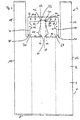
- FIG. 1 shows a plan view of a carrying bag 1 resting on a stack of bags.
- This type of carrying bag is also called a shirt carrying bag because of its attachment of the handles 16 and 18 to the bag body 2.
- the bag body 2 comprises a front wall 4 and a rear wall 6 with a closed bottom end 8 and closed sides 12 and 14 which are substantially parallel. Opposite the bottom end 8 is the open mouth end 10 of the bag body 2.
- the opening end 10 is formed by the upper edges of the front wall 4 and rear wall 6.
- the grips 16 and 18 extend away from the bag body 2 and are arranged on the opposite side edges. In the middle between the handles 16 and 18 extends from the opening end 10 of a front strip 20 which is integrally connected to the front wall 4.
- a corresponding rear strip also extends from the rear wall 6 away from the opening end 10 and is preferably the same size and shape as the front strip 20.
- the front strip 20 and the rear strip are immediately adjacent to the opening end 10 an indentation or a narrower section 24 in the direction of the upper end 34 of the front strip 20 widens towards this strip Both sides again first to then uniformly to thin in the direction of the upper end 34. It is advantageous if the width of the upper end 34 of the front strip 20 is selected such that it is greater than the transverse extent of the narrow portion 24.
- the lateral extension points 40 and 42 of the upper portion 34 of the front strip 20 are so far apart that the imaginary lines 44 and 46 emanating from these points parallel to the side walls cut the front strip 20 above the indentation 24, but do not pass through this narrow section 24, but laterally outside of the closest points 48 and 50 of this indentation 24 run. In this way, a tearing of the front wall 4 when removing the front strip 20 can be prevented.
- To the carrying bag 1 further includes a holding device 22.
- This holding device is composed of an upper portion or bracket 32 and at right angles in the direction of the bag body extending portions or connecting arms 28 and 30 together. These lateral sections or side arms are fastened to the front wall 4 and the rear wall 6 (not shown) at a distance from the gripping pieces 16 and 18.
- the weakening line can lie directly in the region of the upper edge course of the opening end 10 (not shown).
- the weakened area or the weakening line between the pocket body and holding device is preferably located at a distance in the direction of the upper web 32 in the side arms 28 and 30 it already out when, as shown, the lines of weakness 36 and 38 are arranged only slightly above the opening end 10.
- these weakening lines start at a height at which the narrow portion 24 merges into the widening portion 26.
- the upper portion 34 of the front strip 20 is separably connected to the bracket portion 32 of the holding device 22.
- this separable connection extends across a parting line 54 substantially transverse to the longitudinal axis of the carrier bag and over lateral lines of weakness 80 and 82 extending from the parting line 54 towards the opening end.
- the dividing line 54 can be present both as a separable weakening or perforation line and as an already completely severed line. Especially in the latter case, the upper portions 34 of front and back strips in a stack are mostly cold-blocked for better handling.
- the upper portion 34 of the front strip 20 is in this case slightly inserted into the bracket portion 32 of the holding device 22.
- the weakened areas thus extend over the sections 80, 82 and optionally 54, in a preferred embodiment, the holding device 22 in the region of the lateral sections or sidearms 28 and 30 extending about in the direction of the front strip bulges 40 and 42. These bulge areas are advantageously suitable for blocking the holding device of the bag stack. Further blocking pressure points may then be arranged on the upper web 32 of the holding device 22 (represented by the blocking points 56, 58, 60 and 62), as shown.
- two openings 68 and 70 are provided through which two gripping arms of a suitable stand device can be passed to hold the bag stack.
- the preceding statements concerning the holding device 22 and the front strip 20 apply equally to the rear strip and the holding device.
- FIG. 1 A second embodiment of the carrying bag according to the invention or of the pocket stack according to the invention is shown in FIG.
- This second embodiment 1 differers from the first embodiment 1, as shown in Figure 1, reproduced, solely in that the lateral portions 28' and 30 'of the holding device 22' no longer open into the upper opening end 10 of the bag body 2, but each are separably connected to the front strip 20, in such a way that still two through openings 68 'and 70' remain, can be guided by the gripping arms of a stand device.
- These lateral portions or side arms 28 'and 30' preferably open in opposite areas of the front strip 20, which adjoin the narrow portion 24.
- the narrow region 24 is preferably arranged directly adjacent to the opening end 10.
- the preceding statements regarding the front strip 20 of the second embodiment 1 'and its interaction with the holding device apply equally to the rear strip (not shown) and the holding device.
- the pocket stack according to the invention shown by way of example on the first embodiment 1 of a carrying bag according to the invention shown in FIG. 1, can be operated in such a way that first of the above-lying carrying bag 1, the front strip 20 in the upper section 34 is removed via the separable portions 80 and 82 and optionally also 54 of the holding device 22.
- the front strip is first to be separated from the rear strip.
- the lines of weakness 36 and 38 next, so that the front wall 4 of the holding device 22 dissolves.
- the corresponding weakening lines between the rear wall 6 and the holding device to solve.
- both the first embodiment and the second embodiment of the carrying bag according to the invention or the bag stack according to the invention are characterized in that there is no connection between the holding or fastening device 22 and the carrying loops or gripping pieces 16 and 18 via a weakened region whose components ,
Abstract
Description
Die vorliegende Erfindung betrifft eine Kunststofftragetasche sowie einen Taschenstapel, umfassend eine Vielzahl an erfindungsgemäßen Kunststofftragetaschen.The present invention relates to a plastic carrier bag and a bag stack comprising a plurality of plastic carrier bags according to the invention.
Künststofftragetaschen werden vielfältigst im Einzel- und Großhandel eingesetzt. Sie haben platzsparend deponiert werden zu können und müssen dem Nutzer stets in gleicher Zuverlässigkeit in großer Zahl zur Verfügung stehen. Zu dem Zweck haben sich Taschenstapel etabliert, wie man sie z.B. regelmäßig an Gemüsetheken von Supermärkten findet. Solche Taschenstapel können z.B. in geeigneten Ständervorrichtungen eingehängt werden, um dem Nutzer zur Verfügung zu stehen. Gattungsgemäße Taschenstapel finden sich in den beiden
Es wäre daher wünschenswert, auf Taschenstapel zurückgreifen zu können, die nicht mit den Nachteilen der vorangehend beschriebenen gattungsgemäßen Taschenstapel behaftet sind. Der vorliegenden Erfindung lag daher die Aufgabe zugrunde, Taschenstapel zur Verfügung zu stellen, die eine zuverlässige Handhabung und ein flexibles Abreißen eines jeden einzelnen Taschenbeutels gewährleisten, insbesondere auch für die letzten bzw. untersten Taschen eines Taschenstapels, wobei die Massenfertigung unproblematisch sein und vollständig automatisiert vorgenommen werden kann. Der Erfindung lag ferner die Aufgabe zugrunde, eine Kunststofftragetasche zur Verfügung zu stellen, die in der Weise konzipiert ist, daß sie in einem Taschenstapel verwendet werden kann, der den vorangehend genannten Anforderungen genügt.It would therefore be desirable to be able to resort to pocket stack, which are not afflicted with the disadvantages of the generic pocket stack described above. The present invention therefore an object of the invention to provide bag stacks available that ensure reliable handling and a flexible tearing of each bag pocket, especially for the last or lowermost pockets of a bag stack, the mass production to be unproblematic and completely automated can be. A further object of the present invention is to provide a plastic carrier bag which is designed in such a way that it can be used in a pocket stack which satisfies the requirements mentioned above.
Demgemäß wurde eine Kunststofftragetasche gefunden, nachfolgend auch erste Ausgestaltung genannt, umfassend eine Vorderwand und eine Rückwand, wobei die Vorder- und Rückwand einen Taschenkörper definieren mit einem im wesentlichen geschlossen Bodenende und zumindest bereichsweise geschlossenen Seiten und einem zumindest bereichsweise offenen, dem Bodenende gegenüberliegenden Öffnungsende, zwei voneinander beabstandete Griffstücke, und mindestens eine Haltevorrichtung für die Tragetasche, wobei die Vorderwand einen, insbesondere einstückig verbundenen, vorderen Streifen aufweist, der sich zwischen den zwei Griffstücken weg von dem Öffnungsende erstreckt, und wobei der vordere und/oder hintere Streifen sowie die Rückwand einen, insbesondere einstückig verbundenen, hinteren Streifen aufweist, der sich zwischen den zwei Griffstücken weg von dem Öffnungsende erstreckt, und wobei die Vorderwand und/oder die Rückwand jeweils über das zwischen den zwei Griffstücken befindliche Öffnungsende von Vorder- oder Rückwand mit der Haltevorrichtung über mindestens einen Schwächungs- oder Porforationsbereich trennbar verbunden sind.Accordingly, a plastic carrier bag was found, hereinafter also referred to as the first embodiment comprising a front wall and a rear wall, wherein the front and rear walls define a bag body having a substantially closed bottom end and at least partially closed sides and an at least partially open, opposite the bottom end opening end, two spaced apart grips, and at least one holding device for the carrier bag, wherein the front wall has a, in particular integrally connected, front strip which extends between the two grips away from the opening end, and wherein the front and rear strip and the rear wall has an, in particular integrally connected, rear strip which extends between the two gripping pieces away from the opening end, and wherein the front wall and / or the rear wall in each case via the located between the two grips opening end of front or rear wall are separably connected to the holding device via at least one weakening or Porforationsbereich.
Dabei kann insbesondere vorgesehen sein, daß der vordere und/oder der hintere Streifen jeweils über das zwischen den zwei Griffstücken befindliche Öffnungsende von Vorder- oder Rückwand mit der Haltevorrichtung über mindestens einen Schwächungs- oder Perforationsbereich trennbar verbunden sind.It can be provided in particular that the front and / or the rear strip are each connected via the opening located between the two gripping pieces opening end of the front or rear wall with the holding device via at least one weakening or perforation.
Eine erfindungsgemäße Ausführungsform kann demgemäß in der Weise gestaltet sein, daß der vordere bzw. der hintere Streifen und die Haltevorrichtung separat oder trennbar verbunden nebeneinander vorliegen, wobei die Haltevorrichtung z.B. über eine geeignete Öffnung oder einen Durchgriff verfügen kann, um die Tasche bzw. den Taschenstapel an einer Ständervorrichtung aufzuhängen. Beim Abziehen der Tragetasche verbleibt nun der vordere bzw. hintere Streifen an der Tasche, während sich die Haltevorrichtung von dem Taschenkörper trennt. Anstatt separat nebeneinander vorzuliegen, können, wie geschildert, Haltevorrichtung und vorderer bzw. hinterer Streifen selber wiederum über trennbare Schwächungsbereiche miteinander verbunden sein.An embodiment of the invention may accordingly be designed in such a way that the front and the rear strip and the holding device are present separately or separably connected next to each other, the holding device being e.g. can have a suitable opening or a passage to hang the bag or the stack of bags on a stand device. When removing the carrier bag now remains the front or rear strip on the bag, while the holding device separates from the bag body. Instead of being present separately next to each other, as described, holding device and front or rear strip itself can in turn be connected to one another via separable weakened areas.
Hierbei sind solche Ausführungsformen besonders bevorzugt, bei denen die Haltevorrichtung mindestens zwei seitliche Verbindungsabschnitte zum Taschenkörper und einen diese Verbindungsabschnitte verbindenden Bügelabschnitt aufweist, wobei der vordere und/oder der hintere Streifen zwischen zwei seitlichen Verbindungsabschnitten vorliegen und mit dem Bügelabschnitt trennbar verbunden sind. Insbesondere werden zwischen dem vorderen bzw. hinteren Streifen und den links und rechts hiervon befindlichen seitlichen Verbindungsabschnitten der Haltevorrichtung Durchgriffsöffnungen für Greifarme einer geeigneten Spendervorrichtung gelassen.In this case, those embodiments are particularly preferred in which the holding device has at least two lateral connecting sections to the bag body and a connecting these connecting portions bracket portion, wherein the front and / or the rear strip between two lateral connecting portions and are separably connected to the bracket portion. In particular, passage openings for gripping arms of a suitable dispensing device are left between the front and rear strips and the left and right lateral connecting sections of the holding device.
Die seitlichen Verbindungsabschnitte können grundsätzlich in beliebige Orientierung an dem diese Verbindungsabschnitte verbindenden Bügelabschnitt ansetzen, solange gewährleistet ist, daß eine trennbare Verbindung mit dem Taschenkörper bzw. Vorder- und/oder Rückwand eingegangen werden kann. In einer Ausführungsform können diese seitlichen Verbindungsabschnitte beispielsweise senkrecht zu dem Bügelabschnitt, der bevorzugt quer zur Längsachse der Tasche verläuft, angeordnet sein. Während hierbei die seitlichen Verbindungsabschnitte im Bereich des Öffnungsrandes Schwächungsbereiche aufweisen, verfügt der vorderer bzw. hinterer Streifen, insbesondere an dem dem Öffnungsende gegenüberliegenden Ende über einen trennbaren Verbindungs- bzw. Schwächungsbereich mit dem Bügelabschnitt, der die seitlichen Verbindungsabschnitte verbindet.The lateral connection sections can basically begin in any orientation on the bracket section connecting these connection sections, as long as it is ensured that a separable connection with the bag body or the front and / or rear wall can be received. In one embodiment, these lateral connecting sections can be arranged, for example, perpendicular to the strap section, which preferably runs transversely to the longitudinal axis of the pocket. While in this case the lateral connecting portions have weakening areas in the region of the opening edge, the front or rear strip, in particular at the end opposite the opening end, has a separable connection or weakening area with the bow section connecting the lateral connecting sections.
Die Schwächungs- bzw. Perforationsbereiche zwischen der Haltevorrichtung, insbesondere den seitlichen Verbindungsarmen und dem Taschenkörper bzw. der Vorder- bzw. Rückseite der Tragetasche können hierbei im Bereich bzw. auf der Höhe des Öffnungsrandes liegen, oberhalb des Öffnungsrandes oder auch unterhalb des Öffnungsrandes, d.h. eingelassen in den Taschenkörper. Bevorzugt sind die Perforationsbereiche geringfügig oberhalb des Öffnungsrandes angeordnet.The weakening or perforation areas between the holding device, in particular the lateral connecting arms and the pocket body or the front or rear of the carrying bag can hereby lie in the region or at the level of the opening edge, above the opening edge or even below the opening edge, i. taken in the bag body. Preferably, the perforation areas are arranged slightly above the opening edge.
Die der Erfindung zugrunde liegende Aufgabe wird ferner gelöst durch eine Kunststoffiragetasche, nachfolgend auch zweite Ausgestaltung genannt, umfassend eine Vorderwand und eine Rückwand, wobei die Vorder- und Rückwand einen Taschenkörper definieren mit einem im wesentlichen geschlossen Bodenende und zumindest bereichsweise geschlossenen Seiten und einem zumindest bereichsweise offenen, dem Bodenende gegenüberliegenden Öffnungsende, zwei voneinander beanstandete Griffstücke, und mindestens eine Haltevorrichtung für die Tragetasche, wobei die Vorderwand einen vorderen Streifen umfaßt, der sich zwischen den zwei Griffstücken weg von dem Öffnungsende erstreckt, wobei die Rückwand einen hinteren Streifen umfaßt, der sich von zwischen den zwei Griffstücken weg dem Öffnungsende erstreckt, und wobei die Haltevorrichtung an mindestens einem Verbindungsabschnitt über Schwächungs- oder Perforationsbereiche trennbar mit dem vorderen und/oder hinteren Streifen verbunden vorliegt.The object underlying the invention is further achieved by a Kunststoffiragetasche, hereinafter also referred to as the second embodiment, comprising a front wall and a rear wall, wherein the front and rear walls define a bag body having a substantially closed bottom end and at least partially closed sides and an at least partially open mouth end opposite the bottom end, two gripping pieces spaced apart from each other, and at least one holding device for the carrying case, the front wall comprising a front strip extending between the two handles away from the opening end, the rear wall comprising a rear strip which extends extending from between the two gripping pieces away from the opening end, and wherein the holding device at least at one connecting portion via weakening or perforation regions separably connected to the front and / or rear strip is present.
Dabei ist insbesondere vorgesehen, daß die Haltevorrichtung an mindestens drei beabstandeten Verbindungsabschnitten über Schwächungs- oder Perforationsbereiche trennbar mit dem vorderen und/oder hinteren Streifen verbunden vorliegt. Dieses kann beispielsweise dadurch bewerkstelligt werden, daß der dem Öffnungsende gegenüberliegende Abschnitt des vorderen bzw. hinteren Streifens mit der Haltevorrichtung an einem ersten Abschnitt trennbar verbunden ist und daß die Haltevorrichtung über sich in Richtung des Öffnungsendes erstreckende Abschnitte verfügt, die näher zum Öffnungsende hin mit dem vorderen bzw. hinteren Streifen eine trennbare Verbindung eingehen. Selbstverständlich ist es ebenfalls möglich, daß z.B. der vordere bzw. hintere Streifen nur an einer einzigen Stelle bzw. an einem einzigen Verbindungsabschnitt, insbesondere an dem dem Öffnungsende gegenüberliegenden Ende von vorderem bzw. hinterem Streifen trennbar verbunden mit diesen vorliegt. Eine derartige Haltevorrichtung kann z.B. ein Loch bzw. eine Öffnung zum Einfügen eines Durchgreifarms einer Ständervorrichtung aufweisen.It is provided in particular that the holding device is present connected to at least three spaced connecting portions via weakening or perforation separable with the front and / or rear strip. This can be accomplished, for example, in that the portion of the front or rear strip opposite the opening end is detachably connected to the holding device at a first portion is and that the holding device has extending toward the opening end portions which form a separable connection closer to the opening end with the front and rear strips. Of course, it is also possible that, for example, the front or rear strip is present only at a single point or on a single connecting portion, in particular at the opposite end of the opening end of the front and rear strips separably connected to these. Such a holding device may, for example, have a hole or an opening for inserting a punch-through arm of a stand device.
Die erfindungsgemäßen Kunststofftragetaschen zeichnen sich demgemäß dadurch aus, daß sie keine trennbare Verbindungspunkte oder -abschnitte mehr mit den Griffstücken aufzuweisen haben. Während bei der ersten Ausgestaltung der erfindungsgemäßen Kunststofftragetasche die Haltevorrichtung trennbare Verbindungsbereiche mit dem Öffnungsende des Taschenkörpers sowie insbesondere auch mit dem vorderen und/oder hinteren Streifen aufweist, verfügt die zweite Ausgestaltung der erfindungsgemäßen Kunststofftragetasche über eine Haltevorrichtung, die ausschließlich trennbare Verbindungsbereiche mit dem vorderen und/oder hinteren Streifen aufweist.The plastic carrier bags according to the invention are accordingly distinguished by the fact that they no longer have separable connection points or sections with the grips. While in the first embodiment of the plastic carrying bag according to the invention, the holding device has separable connection areas with the opening end of the bag body and in particular also with the front and / or rear strip, the second embodiment of the plastic carrier bag according to the invention has a holding device, the exclusively separable connection areas with the front and / or. or rear strip.
Dabei kann vorgesehen sein, daß die trennbare Verbindung zwischen dem vorderen Streifen und der Haltevorrichtung und/oder dem hinteren Streifen und der Haltevorrichtung und/oder dem Öffnungsende von Vorder- und/oder Rückwand mit der Haltevorrichtung über mindestens eine Schwächungs- oder Perforationslinie bewerkstelligt wird.It can be provided that the separable connection between the front strip and the holding device and / or the rear strip and the holding device and / or the opening end of the front and / or rear wall is accomplished with the holding device via at least one weakening or perforation.
Die Haltevorrichtung liegt bevorzugt zwischen den beabstandeten Griffstücken oberhalb des Öffnungsendes vor.The holding device is preferably located between the spaced handles above the opening end.
In einer besonders bevorzugten Ausführungsform ist vorgesehen, daß der vordere und/oder der hintere Streifen an dem dem Öffnungsende gegenüberliegenden Bereich mit der Haltevorrichtung trennbar verbunden ist bzw. sind.In a particularly preferred embodiment, provision is made for the front and / or the rear strip to be separably connected to the holding device at the region opposite the opening end.
Bei diesem Bereich handelt es sich im allgemeinen um den obersten Abschnitt von vorderem und/oder hinterem Streifen, z.B. wenn die Tragetasche auf einer Spendervorrichtung hängend zur Verfügung gestellt wird. Das Einhängen der Kunststofftragetasche über geeignete Greifarme der Spendervorrichtung gelingt mit Hilfe der Haltevorrichtung, die geeignete Eingrifföffnungen zur Verfügung stellt.This area is generally the topmost portion of the front and / or back strip, for example, when the carrier bag is suspended from a dispenser. The attachment of the plastic carrier bag via suitable gripping arms of the dispensing device is achieved by means of the holding device, which provides suitable engagement openings.
Hierbei zeichnet sich die erste Ausgestaltung der erfindungsgemäßen Tragetasche dadurch aus, daß die Haltevorrichtung zusammen mit dem vorderen und/oder hinteren Streifen und dem Öffnungsende mindestens zwei Halteöffnungen bildet. Für die zweite Ausgestaltung der erfindungsgemäßen Tragetasche ist diesbezüglich vorzugsweise vorgesehen, daß die Haltevorrichtung zusammen mit dem vorderen und/oder hinteren Streifen mindestens zwei Halteöffnungen ausbildet.Here, the first embodiment of the carrying bag according to the invention is characterized in that the holding device forms at least two holding openings together with the front and / or rear strip and the opening end. For the second embodiment of the carrying bag according to the invention in this regard is preferably provided that the holding device forms at least two holding openings together with the front and / or rear strip.
Trennbar verbunden im Sinne der Erfindung soll bedeuten, daß ein zerstörungsfreies Trennen der Tragetaschen gelingt.Separately connected within the meaning of the invention is intended to mean that a nondestructive separation of the carrier bags succeeds.
Die erfindungsgemäßen Tragetaschen sind in einer besonders bevorzugten Ausführungsform dadurch gekennzeichnet, daß zumindest ein Abschnitt von vorderem und/oder hinterem Streifen quer zur Längsachse der Tragetasche schmaler dimensioniert ist, als ein sich mittelbar oder unmittelbar in Richtung weg von dem Öffnungsende erstreckender Abschnitt von vorderem oder hinterem Streifen.The carrier bags according to the invention are characterized in a particularly preferred embodiment in that at least a portion of front and / or rear strip is dimensioned transversely to the longitudinal axis of the carrier bag narrower than a directly or indirectly extending in the direction away from the opening end portion of front or rear strips.
Dabei kann insbesondere vorgesehen sein, daß der schmale Abschnitt des vorderen und/oder hinteren Streifens benachbart ist zum Öffnungsende. Indem der vordere und/oder hintere Streifen, insbesondere jedoch der vordere Streifen einer Tragetasche, einen schmaleren Abschnitt bzw. eine Einbuchtung bzw. Einbauchung aufweist, kann ein Einreißen der Taschenwand vollständig unterbunden werden. Die vorangehend geschilderte Maßnahme macht sich insbesondere auch bei solchen erfindungsgemäßen Tragetaschen bemerkbar, bei denen der vordere und hintere Streifen jeweils einstückig mit der oder aus dem selben Material wie die Vorder- bzw. Rückwand gefertigt sind. Als besonders effektiv hatte sich erwiesen, wenn man die Einbuchtung bzw. den schmalen Abschnitt unmittelbar in dem sich an dem Öffnungsende anschließenden Bereich von vorderem bzw. hinterem Streifen vorsieht.It can be provided in particular that the narrow portion of the front and / or rear strip is adjacent to the opening end. By having the front and / or rear strip, but in particular the front strip of a carrying bag, a narrower portion or a recess or indentation, a tearing of the pocket wall can be completely prevented. The above-described measure is particularly noticeable in such carrying bags according to the invention, in which the front and rear strips are each made in one piece with or made of the same material as the front or rear wall. It has proven to be particularly effective to provide the indentation or narrow section directly in the region of the front and rear strips adjoining the opening end.
Für die zweite Ausgestaltung der erfindunsgemäßen Tragetasche hatte es sich im Hinblick auf die vorangehend geschilderte Ausführungsform als sehr vorteilhaft erwiesen, wenn zwei Verbindungsabschnitte der Haltevorrichtung mit dem vorderen- und/oder hinteren Streifen sich oberhalb des schmalen Abschnitts befinden, wobei der dritte Verbindungsabschnitt an dem dem Öffnungsende gegenüberliegenden Bereich von vorderem und/oder hinterem Streifen vorliegt.For the second embodiment of the carrying bag according to the invention, it was found to be very advantageous in view of the above-described embodiment, when two connecting portions of the holding device with the front and / or rear strip are above the narrow portion, wherein the third connecting portion at the Opening opposite region of front and / or rear strip is present.
Erfindungsgemäße Tragetaschen zeichnen sich ferner insbesondere dadurch aus, daß die Schwächungs- oder Perforationsbereiche der Haltevorrichtung mit der Vorder- und/oder Rückwand im Bereich des Öffnungsendes vorliegen. Bei dieser Variante liegt der Schwächungsbereich bzw. die Schwächungslinie im wesentlichen am oberen Rand des Taschenkörpers vor und besonders bevorzugt im Verlauf der Oberkante des Öffnungsendes des Taschenkörpers.Inventive carrier bags are also characterized in particular by the weakening or perforation of the holding device with the front and / or Rear wall in the region of the opening end present. In this variant, the weakened area or the weakening line is present essentially at the upper edge of the pocket body and particularly preferably in the course of the upper edge of the opening end of the pocket body.
In einer besonders bevorzugten alternativen Ausführungsform kann vorgesehen sein, daß die Schwächungs- oder Perforationsbereiche der Haltevorrichtung mit der Vorder- und/oder Rückwand beabstandet von dem Öffnungsende in der Haltevorrichtung vorliegen. Bei dieser Variante liegen die Schwächungsbereiche bzw. Schwächungslinien beabstandet von dem oberen Rand bzw. der Oberkante des Öffnungsendes des Taschenkörpers und damit oberhalb desselben vor. Bei dieser Variante wird beobachtet, daß die Gefahr des Einreißens des Taschenkörpers im Bereich der Schwächungs- oder Perforationsbereiche beim Abziehen der Tasche nochmals verringert ist. Selbstverständlich kann der Schwächungs- bzw. Perforationsbereich auch unterhalb des Öffnungsende, z.B. eingelassen in den Taschenkörper, vorliegen.In a particularly preferred alternative embodiment it can be provided that the weakening or perforation regions of the holding device with the front and / or rear wall are spaced from the opening end in the holding device. In this variant, the weakened areas or lines of weakness are spaced from the upper edge or the upper edge of the opening end of the bag body and thus above it. In this variant, it is observed that the risk of tearing of the bag body in the region of weakening or perforation areas when removing the bag is further reduced. Of course, the weakening or perforation area may also be below the opening end, e.g. let into the bag body, present.
Bei der in Rede stehenden Ausführungsform ist der obere Bereich des vorderen und/oder hinteren Streifens bevorzugt über eine oder mehrere Schwächungslinien mit der Haltevorrichtung, insbesondere einem querverlaufenden Bügelabschnitt der Haltevorrichtung, trennbar verbunden. Die trennbare Schwächungslinie kann beispielsweise unmittelbar entlang der dem Öffnungsende zugewandten Kante der Haltevorrichtung bzw. Bügelabschnitts dieser Vorrichtung verlaufen, kann jedoch ebenfalls in diese eingelassen sein oder in Richtung auf das Öffnungsende verschoben in dem oberen Bereich des vorderen bzw. hinteren Streifens vorliegen. In der Regel reicht es bereits aus, in dem oberen Bereich von vorderem bzw. hinterem Streifen nur minimale Verbindungspunkte zu belassen, die leicht zu trennen sind, und den übrigen Bereich der Schwächungslinie bereits vollständig durchtrennt zu haben.In the embodiment in question, the upper region of the front and / or rear strip is preferably connected via one or more lines of weakness with the holding device, in particular a transverse strap portion of the holding device, separably connected. The separable line of weakness may, for example, extend directly along the edge of the holding device or bracket section of this device facing the opening end, but may likewise be embedded in the latter or displaced towards the opening end in the upper region of the front or rear strip. In general, it is already sufficient to leave in the upper region of the front or rear strip only minimal connection points, which are easy to separate, and to have already completely severed the remaining area of the weakening line.
In einer bevorzugten Ausgestaltung liegen die vorderen und hinteren Streifen verblockt, insbesondere kaltverblockt, vor.In a preferred embodiment, the front and rear strips are blocked, in particular cold blocked before.
Bevorzugt sind der vordere und/oder der hintere Streifen und/oder die Haltevorrichtung im wesentlichen spiegelsymetrisch ausgebildet. Bei einer derartigen Gestaltung lassen sich die beim Abziehen der Tragetasche von einem Taschenstapel wirkenden Kräfte am ehesten gleichmäßig verteilen, wodurch Materialbeeinträchtigungen und Handhabungsschwierigkeiten nochmals verringert werden.Preferably, the front and / or the rear strip and / or the holding device are formed substantially mirror-symmetrical. With such a design, the forces acting on a pocket stack during the removal of the carrier bag are best distributed evenly, which further reduces material impairments and handling difficulties.
Die Griffstücke setzen in der Regel direkt am Tragekörper, insbesondere dessen Öffnungsende, an, sind ferner insbesondere mit dem Taschenkörper einstückig verbunden, und erstrecken sich im allgemeinen von dem Öffnungsende weg.The grips are usually directly on the support body, in particular its opening end, on, are also in particular integrally connected to the bag body, and generally extend away from the opening end.
Die der Erfindung zugrunde liegende Aufgabe wird des weiteren gelöst durch einen Taschenstapel, umfassend eine Vielzahl an von in dem Stapel angeordneten erfindungsgemäßen Tragetaschen gemäß der ersten Ausgestaltung oder gemäß der zweiten Ausgestaltung, wobei der hintere Streifen einer Tasche in dem Stapel trennbar verbunden ist mit dem vorderen Streifen der nachfolgenden Tasche in dem Stapel. Eine Vielzahl an Tragetaschen im Sinne der Erfindung umfaßt beispielsweise Stapel mit Zehn oder mehr, insbesondere 100 oder mehr gestapelten Tragetaschen. Selbstverständlich kann ein Stapel auch 1000 und mehr Taschen umfassen. Bei den erfindungsgemäßen Taschenstapeln läßt sich somit durch das Ziehen des vorderen Streifens einer vorderen Tasche die dahinter liegende Tasche über die trennbare Verbindung von hinterem Streifen der vorderen Tasche mit dem vorderen Streifen der dahinter liegenden Tasche öffnen. Außerdem wird durch das Ziehen an dem vorderen Streifen der vorderen Tasche die Verbindung der vorderen Tasche mit der Haltevorrichtung gelöst. Gleichzeitig oder insbesondere im Anschluß an das Trennen der vorderen Tragetasche von der Haltevorrichtung wird durch weiteres Ziehen die trennbare Verbindung zwischen dem hinteren Streifen der vorderen Tasche und dem vorderen Streifen der nachfolgenden Tasche gelöst. Bei dem erfindungsgemäßen Taschenstapel bilden die Haltevorrichtungen der Kunststofftragetasche zusammen die Haltevorrichtung für diesen Stapel. Im allgemeinen sind die Haltevorrichtungen aus dem gleichen Folienmaterial gefertigt wie die Taschenkörper und die Griffstücke und verfügen demgemäß in der Regel über dieselbe Dicke und Beschaffenheit. Zweckmäßigerweise sind die Haltevorrichtungen in dem Stapel verblockt.The object underlying the invention is further solved by a pocket stack comprising a plurality of arranged in the stack according to the invention carrier bags according to the first embodiment or according to the second embodiment, wherein the rear strip of a bag is separably connected in the stack with the front Strip the subsequent pocket in the stack. A plurality of carrier bags according to the invention comprises, for example, stacks of ten or more, in particular 100 or more stacked carrier bags. Of course, a stack may also include 1000 or more pockets. In the bag stacks according to the invention can thus be opened by pulling the front strip of a front pocket, the underlying pocket on the separable connection of the rear strip of the front pocket with the front strip of the underlying pocket. In addition, the connection of the front pocket with the holding device is released by pulling on the front strip of the front pocket. At the same time or in particular following the separation of the front carrying bag from the holding device, the separable connection between the rear strip of the front pocket and the front strip of the subsequent pocket is released by further pulling. In the pocket stack according to the invention, the holding devices of the plastic carrying bag together form the holding device for this stack. In general, the holding devices are made of the same sheet material as the bag bodies and the handles, and thus usually have the same thickness and texture. Conveniently, the holding devices are locked in the stack.
Erfindungsgemäß ist somit vorgesehen, daß der hintere Streifen einer Tasche in dem Stapel trennbar verbunden ist mit dem vorderen Streifen der nachfolgenden Tasche in dem Stapel an einem Streifen-zu-Streifen-Verbindungsbereich, insbesondere -Verbindungspunkt.According to the invention, it is thus provided that the rear strip of a pocket in the stack is detachably connected to the front strip of the subsequent pocket in the stack at a strip-to-strip connection area, in particular connection point.
Hierbei zeichnen sich die erfindungsgemäßen Taschenstapel vorzugsweise dadurch aus, daß die Haltevorrichtung und die Schwächungs- und Perforationsbereiche in der Weise ausgelegt sind, daß durch das Ziehen des vorderen Streifens, um die vorderste Tasche von dem Stapel zu entfernen, die Schwächungs- oder Perforalionsbereiche dieser Tasche eher nachgeben als die trennbare Verbindung von hinterem Streifen dieser Tasche mit dem vorderen Streifen der nachfolgenden Tasche.In this case, the bag stacks according to the invention are preferably characterized in that the holding device and the weakening and perforating are designed in such a way that the weakening or Perforalionsbereiche this pocket by pulling the front strip to remove the frontmost pocket of the stack give rather than the separable connection of the back strip of this bag with the front strip of the subsequent bag.
Dabei ist insbesondere vorgesehen, daß die vorderen und hinteren Streifen aus dem gleichen Material gebildet sind wie die jeweiligen Vorder- und Rückwände.It is particularly provided that the front and rear strips are formed of the same material as the respective front and rear walls.
Gemäß einer besonders bevorzugten Ausführungsform sind die Vorder- und/oder Rückwand einer erfindungsgemäßen Tragetasche zumindest bereichsweise mehrlagig ausgestaltet und können beispielsweise als Gefrier- bzw. Kühltasche verwendet werden. Vorteilhafterweise liegt in einem erfindungsgemäßen Taschenstapel mindestens eine derartige Tragetasche vor. Vorteilhafterweise sind sämtliche Tragetaschen eines solchen Taschenstapels mit derartigen Tragetaschen ausgestattet. In der Regel reicht es aus, die Vorder- und/oder Rückwand zweilagig auszustatten.According to a particularly preferred embodiment, the front and / or rear wall of a carrier bag according to the invention are designed at least partially multi-layered and can be used for example as a freezer or cooler bag. Advantageously, at least one such carrying bag is present in a pocket stack according to the invention. Advantageously, all the carrier bags of such a bag stack are equipped with such carrier bags. In general, it is sufficient to equip the front and / or rear wall in two layers.
Die Haltevorrichtung des Stapels kann demgemäß aus einer Vielzahl an Lagen an Folienmaterial der Vorder- und/oder Rückwand gebildet werden.The holding device of the stack can accordingly be formed from a plurality of layers of film material of the front and / or rear wall.
Für die Anbindung des hinteren Streifens einer Tragetasche mit dem vorderen Streifen der nachfolgenden Tragetasche des Taschenstapels greift man vorzugsweise auf ein geeignetes Haftmittel zurück. Zur Erhöhung der Haftung ist es unter anderem auch möglich, die Rückseite des hinteren Streifens und die Vorderseite des vorderen Streifens der nachfolgenden Tasche zumindest bereichsweise einer Coronar-Behandlung zu unterziehen, um sie insbesondere anschließend zusammenzupressen. Hierbei kann beispielsweise vorgesehen sein, daß das Material des hinteren Streifens in eine in dem vorderen Streifen der nachfolgenden Tragetasche vorliegenden Einbuchtung eingedrückt ist.For the connection of the rear strip of a carrying bag with the front strip of the subsequent carrying bag of the bag stack is preferably accessed on a suitable adhesive. Among other things, to increase the adhesion, it is also possible for the rear side of the rear strip and the front side of the front strip of the subsequent pocket to undergo a corona treatment at least in some areas, in order to then compress them in particular. In this case, for example, be provided that the material of the rear strip is pressed into a present in the front strip of the subsequent carrying bag indentation.
Gemäß einer weiteren Ausführungsform des erfindungsgemäßen Taschenstapels können die vorderen und hinteren Streifen der in diesem Stapel vorliegenden Kunststofftragetaschen, insbesondere im oberen Bereich, miteinander verblockt, insbesondere kaltverblockt, sein.According to a further embodiment of the pocket stack according to the invention, the front and rear strips of the plastic carrier bags present in this stack, in particular in the upper region, can be locked together, in particular cold-blocked.
Die in dem erfindungsgemäßen Taschenstapel vorliegenden erfindungsgemäßen Kunststofftragetaschen sind vorzugsweise gefertigt aus Polyolefinen wie Polypropylen und Polyethylen sowie Copolymeren des Polyethylens und Polypropylens, Polystyrol, Styrol(co)poylmeren, insbesondere ABS, ASA, SAN, MABS und MBS, Poly(meth)acrylaten, Polyestern, insbesondere Polybutylenterephthalat und Polyethylenterephthalat, Polyurethanen, Polyphenylenethern, Polyketonen, Polyamiden, Polyimiden, Polyvinylchloriden, Ethylen/Vinylacetat-Copolymeren, Polyacrylnitril, Polycarbonaten, Polyoxymethylenen, Polysulfonen, Polyphenylensulfonen sowie beliebigen Blends der vorangehenden Kunststoffe.The inventive plastic carrier bags present in the pocket stack according to the invention are preferably made of polyolefins such as polypropylene and polyethylene and copolymers of polyethylene and polypropylene, polystyrene, styrene (co) polymers, in particular ABS, ASA, SAN, MABS and MBS, poly (meth) acrylates, polyesters , in particular polybutylene terephthalate and polyethylene terephthalate, polyurethanes, polyphenylene ethers, polyketones, polyamides, polyimides, polyvinyl chlorides, ethylene / vinyl acetate copolymers, polyacrylonitrile, polycarbonates, polyoxymethylenes, polysulfones, polyphenylene sulfones and any blends of the preceding plastics.
Der vorliegenden Erfindung lag die überraschende Erkenntnis zugrunde, daß sich die Handhabung und Herstellung von Taschenstapeln von Kunststofftragetaschen nochmals vereinfachen und zuverlässiger gestalten läßt, wenn die Halte- bzw. Befestigungsvorrichtung nicht mehr mit den Tragegriffen bzw. Griffstücken verbunden ist. Insbesondere kann der Taschenstapel bis zur letzten Tasche in gleich zuverlässiger Weise aufgebraucht werden, wodurch sich Produktausschuß nochmals minimieren läßt. Außerdem kann mit dem erfindungsgemäßen Taschenstapel bzw. Tragetaschen das Problem des Einreißens der Tragetaschen beim Abziehen bzw. Öffnen nochmals vermindert werden. Dieser Aspekt ist um so bedeutsamer, als aus Gründen der Material- und Kostenersparnis die für Kunststofftragetaschen zum Einsatz kommenden Folienmaterialien noch stets immer dünner werden.The present invention was based on the surprising finding that simplify the handling and production of bag stacks of plastic carrier bags again and make it more reliable when the holding or fastening device is no longer connected to the carrying handles or grips. In particular, the bag stack can be used up to the last bag in the same reliable manner, which can be minimized Produktausschuß again. In addition, the problem of tearing the carrier bags when removing or opening can be further reduced with the bag stack or bags according to the invention. This aspect is all the more important because, for reasons of material and cost savings, the plastic materials used for plastic carrier bags are still getting thinner and thinner.
Weitere Details und Vorteile der vorliegenden Erfindung werden anhand der nachfolgend genannten Abbildungen näher beschrieben. Darin zeigen
Figur 1- eine Draufsicht auf eine erfindungsgemäße Kunststofftragetasche gemäß der ersten Ausgestaltung, und
- Figur 2
- Draufsicht auf eine erfindungsgemäße Kunststofltragetasche gemäß der zweiten Ausgestaltung.
- FIG. 1
- a plan view of a plastic carrier bag according to the invention according to the first embodiment, and
- FIG. 2
- Top view of a plastic carrying bag according to the invention according to the second embodiment.
Figur 1 zeigt eine Draufsicht auf eine auf einem Taschenstapel zuvorderst aufliegende Tragetasche 1. Dieser Tragetaschentyp wird aufgrund seiner Anbringung der Griffstücke 16 und 18 an dem Taschenkörper 2 auch Hemdchen-Tragetasche genannt. Der Taschenkörper 2 umfaßt eine Vorderwand 4 und eine Rückwand 6 mit einem geschlossenen Bodenende 8 und geschlossenen Seiten 12 und 14, die im wesentlichen parallel verlaufen. Dem Bodenende 8 gegenüberliegend befindet sich das offene Öffnungsende 10 des Taschenkörpers 2. Das Öffnungsende 10 wird gebildet durch die oberen Ränder bzw. Oberkanten von Vorderwand 4 und Rückwand 6. Die Griffstücke bzw. -laschen 16 und 18 erstrecken sich weg von dem Taschenkörper 2 und sind an den sich gegenüberliegenden Seitenrändern angeordnet. In der Mitte zwischen den Griffstücken 16 und 18 erstreckt sich von dem Öffnungsende 10 aus ein vorderer Streifen 20, der mit der Vorderwand 4 einstückig verbunden ist. Ein entsprechender hinterer Streifen (nicht abgebildet) erstreckt sich ebenfalls von der Rückwand 6 weg von dem Öffnungsende 10 und verfügt vorzugsweise über die gleiche Größe und Form wie der vordere Streifen 20. Der vordere Streifen 20 sowie der hintere Streifen verfügen unmittelbar benachbart zum Öffnungsende 10 über eine Einbuchtung bzw. einen schmaleren Abschnitt 24 in Richtung des oberen Endes 34 des vorderen Streifens 20 verbreitert sich dieser Streifens zu beiden Seiten zunächst wieder, um anschließend sich gleichförmig in Richtung des oberen Endes 34 zu verdünnen. Hierbei ist von Vorteil, wenn die Breite des oberen Endes 34 des vorderen Streifens 20 derart gewählt wird, daß diese größer ist als die Querausdehnung des schmalen Abschnitts 24. Besonders bevorzugt liegen die seitlichen Ausdehnungspunkte 40 und 42 des oberen Bereichs 34 des vorderen Streifens 20 so weit auseinander, daß die von diesen Punkten parallel zu den Seitenwänden ausgehenden imaginären Linien 44 und 46 den vorderen Streifen 20 oberhalb der Einbuchtung 24 schneiden, diesen schmalen Abschnitt 24 hingegen nicht durchlaufen, vielmehr seitlich außerhalb der am nächsten beieinanderliegenden Punkte 48 und 50 dieser Einbuchtung 24 verlaufen. Auf diese Weise kann ein Einreißen der Vorderwand 4 beim Abziehen des vorderen Streifens 20 verhindert werden.FIG. 1 shows a plan view of a carrying
Zu der Tragetasche 1 gehört ferner eine Haltevorrichtung 22. Diese Haltevorrichtung setzt sich aus einem oberen Abschnitt bzw. Bügel 32 sowie rechtwinklig in Richtung des Taschenkörpers verlaufenden Abschnitten bzw. Verbindungsarmen 28 und 30 zusammen. Diese seitlichen Abschnitte bzw. Seitenarme sind mit der Vorderwand 4 sowie der Rückwand 6 (nicht abgebildet) beabstandet von den Griffstücken 16 und 18 trennbar befestigt. Die Schwächungslinie kann hierbei in einer Ausführungsform direkt im Bereich des Oberkantenverlaufs des Öffnungsendes 10 liegen (nicht abgebildet), bevorzugt befindet sich der Schwächungsbereich bzw. die Schwächungslinie zwischen Taschenkörper und Haltevorrichtung beabstandet in Richtung des oberen Stegs 32 in den Seitenarmen 28 und 30. Hierbei reicht es bereits aus, wenn, wie abgebildet, die Schwächungslinien 36 und 38 nur geringfügig oberhalb des Öffnungsendes 10 angeordnet sind. In einer bevorzugten Ausgestaltung setzen diese Schwächungslinien auf einer Höhe an, auf der der schmale Abschnitt 24 in den sich verbreiternden Abschnitt 26 übergeht. Der obere Abschnitt 34 des vorderen Streifens 20 ist mit dem Bügelabschnitt 32 der Haltevorrichtung 22 trennbar verbunden. In einer bevorzugten Ausgestaltung erstreckt sich diese trennbare Verbindung über eine Trennlinie 54 im wesentlichen quer zur Längsachse der Tragetasche sowie über seitliche Schwächungslinien 80 und 82, die sich von der Trennlinie 54 in Richtung auf das Öffnungsende erstrecken. Die Trennlinie 54 kann sowohl als trennbare Schwächungs- bzw. Perforationslinie als auch als bereits vollständig durchtrennte Linie vorliegen. Insbesondere in letzterem Fall sind die oberen Abschnitte 34 von vorderen und hinteren Streifen in einem Stapel zwecks besserer Handhabung zumeist kaltverblockt. Der obere Abschnitt 34 des vorderen Streifens 20 ist hierbei geringfügig eingelassen in den Bügelabschnitt 32 der Haltevorrichtung 22. Die Schwächungsbereiche erstrekken sich somit über die Abschnitte 80, 82 und gegebenenfalls 54, In einer bevorzugten Ausführungsform verfügt die Haltevorrichtung 22 im Bereich der seitlichen Abschnitte bzw. Seitenarme 28 und 30 über sich in Richtung des vorderen Streifens erstreckende Ausbuchtungen 40 und 42. Diese Ausbuchtungsbereiche eignen sich vorteilhafterweise dazu, die Haltevorrichtung des Taschenstapels zu verblocken. Weitere Verblockungsdruckpunkte können dann, wie abgebildet, auf dem oberen Stegs 32 der Haltevorrichtung 22 angeordnet sein (dargestellt durch die Verblockungspunkte 56, 58, 60 und 62). Durch die Art der Anbringung der Haltevorrichtung 22 an dem Taschenkörper 2 bzw. dem vorderen Streifen 20 werden zwei Öffnungen 68 und 70 geschaffen, durch die zwei Greiffarme einer geeigneten Ständervorrichtung hindurchgeführt werden können, um den Taschenstapel zu halten. Die vorangehenden Ausführungen betreffend die Haltevorrichtung 22 und den vorderen Streifen 20 gelten in gleicher Weise für den hinteren Streifen und die Haltevorrichtung.To the carrying
Eine zweite Ausgestaltung der erfindungsgemäßen Tragetasche bzw. des erfindungsgemäßen Taschenstapels findet sich in Figur 2 abgebildet.A second embodiment of the carrying bag according to the invention or of the pocket stack according to the invention is shown in FIG.
Diese zweite Ausgestaltung 1' unterscheidet sich von der ersten Ausgestaltung 1, wie in Figur 1, wiedergegeben, allein dadurch, daß die seitlichen Abschnitte 28' und 30' der Haltevorrichtung 22' nicht mehr in das obere Öffnungsende 10 des Taschenkörpers 2 münden, sondern jeweils trennbar mit dem vorderen Streifen 20 verbunden sind, und zwar in der Weise, daß noch stets zwei Durchgriffsöffnungen 68' und 70' verbleiben, durch die Greiffarme einer Ständervorrichtung geführt werden können. Diese seitlichen Abschnitte bzw. Seitenarme 28' und 30' münden bevorzugt in sich gegenüber liegenden Bereichen des vorderen Streifens 20, die sich an den schmalen Abschnitt 24 anschließen. Auch bei dieser zweiten Ausgestaltung ist der schmale Bereich 24 bevorzugt unmittelbar benachbart zum Öffnungsende 10 angeordnet. Die Schwächungsbereiche bzw. -linien 72 und 74 zwischen den seitlichen Abschnitten bzw. Seitenarmen 28' und 30' der Haltevorrichtung 22' befinden sich bevorzugt im Bereich des Randverlaufs des vorderen Streifens 20. In einer weiteren bevorzugten Ausführungsform sind die Seitenarme 28' und 30' bzw. die Schwächungsbereiche bzw. -linien 72 und 74 in einem Abschnitt des vorderen Streifens 20 angebracht, der außerhalb der bereits zu Figur 1 erläuternden imaginären Linien 44 und 46 liegt. Die vorangehenden Ausführungen betreffend den vorderen Streifen 20 der zweiten Ausgestaltung 1' und dessen Zusammenspiel mit der Haltevorrichtung gelten in gleicher Weise für den hinteren Streifen (nicht abgebildet) und die Haltevorrichtung.This second embodiment 1 'differs from the
Der erfindungsgemäße Taschenstapel, exemplarisch an der ersten Ausgestaltung 1 einer erfindungsgemäßen Tragetasche gemäß Fig. 1 dargestellt, kann in der Weise bedient werden, daß zunächst von der oben aufliegenden Tragetasche 1 der vordere Streifen 20 im oberen Abschnitt 34 über die trennbaren Abschnitte 80 und 82 sowie gegebenenfalls auch 54 von der Haltevorrichtung 22 entfernt wird. Gegebenenfalls ist bei beispielsweise Kaltverblockung der oberen Bereiche von vorderen und hinteren Streifen eines Stapels zunächst der vordere Streifen von dem hinteren Streifen zu trennen. Durch weiteres Abziehen des vorderen Streifens 20 geben als nächstes die Schwächungslinien 36 und 38 nach, so daß sich die Vorderwand 4 von der Haltevorrichtung 22 löst. Durch noch weiteres Abziehen des vorderen Streifens 20 lösen sich auch die entsprechenden Schwächungslinien zwischen der Rückwand 6 und der Haltevorrichtung. Noch weiteres Abziehen des vorderen Streifens 20 setzt die trennbare Verbindung zwischen den hinteren Streifen der vorderen Tasche 1 und dem vorderen Streifen der nachfolgenden Tasche des Taschenstapels zunächst unter Spannung und führt sodann zur Trennung. Hierfür ist jedoch eine gewisse Kraft aufzubringen, die zunächst dazu führt, daß die nachfolgende Tasche sich öffnet, Auf diese Weise entfällt automatisch ein Entzwirbeln aneinander haftender dünner Folienwände. Dadurch daß die Haltevorrichtung der Tragetaschen verblockt ist, verbleiben nach dem Abreißen individueller Tragetaschen auf der Spendervomchtung für den Taschenstapel.The pocket stack according to the invention, shown by way of example on the
Ersichtlich zeichnen sich sowohl die erste Ausgestaltung als auch die zweite Ausgestaltung der erfindungsgemäßen Tragetasche bzw. der erfindungsgemäßen Taschenstapel dadurch aus, daß zwischen der Halte- bzw. Befestigungsvorrichtung 22 und den Trageschlaufen bzw. Griffstücken 16 und 18 keine über einen Schwächungsbereich deren Bestandteile trennbare Verbindung besteht.Obviously, both the first embodiment and the second embodiment of the carrying bag according to the invention or the bag stack according to the invention are characterized in that there is no connection between the holding or
Die in der vorstehenden Beschreibung, in den Ansprüchen sowie in den Zeichnungen offenbarten Merkmale der Erfindung können sowohl einzeln als auch in jeder beliebigen Kombination für die Verwirklichung der Erfindung in ihren verschiedenen Ausführungsformen wesentlich sein.The features of the invention disclosed in the foregoing description, in the claims and in the drawings may be essential both individually and in any combination for the realization of the invention in its various embodiments.
- 11
- erste Ausgestaltung einer Tragetaschefirst embodiment of a carrying bag
- 1'1'
- zweite Ausgestaltung einer Tragetaschesecond embodiment of a carrying bag
- 22
- Taschenkörperbag body
- 44
- Vorderwandfront wall
- 66
- Rückwandrear wall
- 1010
- offenes Öffnungsendeopen opening end
- 1616
- Griffstückgrip
- 1818
- Griffstückgrip
- 2020
- vorderer Streifenfront strip
- 2222
- Haltevorrichtungholder
- 2424
- schmaler Abschnittnarrow section
- 2626
- verbreiterter Abschnittwidened section
- 2828
- seitlicher Verbindungsannlateral connection
- 28'28 '
- seitlicher Verbindungsarmlateral connecting arm
- 3030
- seitlicher Verbindungsarmlateral connecting arm
- 30`30`
- seitlicher Verbindungsarmlateral connecting arm
- 3232
- Bügelhanger
- 3434
- oberes Ende des vorderen Streifensupper end of the front strip
- 3636
- Schwächungslinieweakening line
- 3838
- Schwächungslinieweakening line
- 4040
- Ausbuchtungbulge
- 4242
- Ausbuchtungbulge
- 4444
- imaginäre Linieimaginary line
- 4646
- imaginäre Linieimaginary line
- 4848
- Eckpunktvertex
- 5050
- Eckpunktvertex
- 5454
- Trennlinieparting line
- 5656
- VerblockungspunktVerblockungspunkt
- 5858
- VerblockungspunktVerblockungspunkt
- 6060
- VerblockungspunktVerblockungspunkt
- 6262
- VerblockungspunktVerblockungspunkt
- 68, 6868, 68
- DurchgriffsöffnungThrough opening
- 70, 70'70, 70 '
- DurchgriffsöffnungThrough opening
- 7272
- Schwächungslinieweakening line
- 7474
- Schwächungslinieweakening line
- 8080
- seitliche Trennlinie des oberen Abschnitts des vorderen Streifenslateral dividing line of the upper portion of the front strip
- 8282
- seitliche Trennline des oberen Abschnitts des vorderen Streifenslateral dividing line of the upper section of the front strip
Claims (27)
die Haltevorrichtung mindestens zwei seitliche Verbindungsabschnitte zum Taschenkörper und einen diese Verbindungsabschnitte verbindenden Bügelabschnitt aufweist, wobei der vordere und/oder der hintere Streifen zwischen zwei seitlichen Verbindungsabschnitten vorliegen und mit dem Bügelabschnitt trennbar verbunden sind.Plastic carrying bag according to claim 2, characterized in that
the holding device has at least two lateral connecting sections to the pocket body and a strap section connecting these connecting sections, wherein the front and / or the rear strip are present between two lateral connecting sections and are detachably connected to the strap section.
die Haltevorrichtung an mindestens drei beabstandeten Verbindungsabschnitten über Schwächungs- oder Perforationsbereiche trennbar mit dem vorderen und/oder hinteren Streifen verbunden vorliegt.Plastic carrier bag according to claim 4, characterized in that
the holding device is separably connected to the front and / or rear strip via at least three spaced connecting sections via weakening or perforating regions.
die trennbare Verbindung zwischen dem vorderen Streifen und der Haltevorrichtung und/oder dem hinteren Streifen und der Haltevorrichtung und/oder dem Öffnungsende von Vorder- und/oder Rückwand mit der Haltevorrichtung über mindestens eine Schwächungs- oder Perforationslinie bewerkstelligt wird.Carrying case according to one of the preceding claims, characterized in that
the separable connection between the front strip and the holding device and / or the rear strip and the holding device and / or the opening end of the front and / or rear wall is accomplished with the holding device via at least one weakening or perforation line.
der vordere und/oder der hintere Streifen an dem dem Öffnungsende gegenüberliegenden Bereich mit der Haltevorrichtung trennbar verbunden ist bzw. sind.Carrying case according to one of the preceding claims, characterized in that
the front and / or the rear strip is separably connected to the holding device at the region opposite the opening end.
die Haltevorrichtung zusammen mit dem vorderen und/oder hinteren Streifen und dem Öffnungsende mindestens zwei, insbesondere symmetrische, Halteöffnungen bildet.Holding device according to one of claims 1 to 3, characterized in that
the holding device together with the front and / or rear strip and the opening end forms at least two, in particular symmetrical, holding openings.
die Haltevorrichtung zusammen mit dem vorderen und/oder hinteren Streifen mindestens zwei, insbesondere symmetrische, Halteöffnungen ausbildet.Carrying case according to one of the preceding claims 4 to 7, characterized in that
the holding device forms at least two, in particular symmetrical, holding openings together with the front and / or rear strip.
der schmale Abschnitt des vorderen und/oder hinteren Streifens benachbart ist zum Öffnungsende.Carrying case according to claim 10, characterized in that
the narrow portion of the front and / or rear strip is adjacent to the opening end.
die Schwächungs- oder Perforationsbereiche der Haltevorrichtung mit der Vorder- und/oder Rückwand im Bereich des Öffnungsendes vorliegen.Carrying case according to one of the preceding claims, characterized in that
the weakening or perforation regions of the holding device are present with the front and / or rear wall in the region of the opening end.
die Schwächungs- oder Perforationsbereiche der Haltevorrichtung mit der Vorder- und/oder Rückwand beabstandet von dem Öffnungsende, insbesondere in der Haltevorrichtung, vorliegen.Carrying case according to one of claims 1 to 12, characterized in that
the weakening or perforation areas of the holding device with the front and / or rear wall spaced from the opening end, in particular in the holding device, are present.
der vordere und/oder der hintere Streifen und/oder die Haltevorrichtung im wesentlichen spiegelsymmetrisch ausgebildet sind.Carrying case according to one of the preceding claims, characterized in that
the front and / or the rear strip and / or the holding device are formed substantially mirror-symmetrical.
die Griffstücke sich von dem Öffnungsende weg erstrecken.Carrying case according to one of the preceding claims, characterized in that
the grips extend away from the opening end.
der hintere Streifen einer Tasche in dem Stapel trennbar verbunden ist mit dem vorderen Streifen der nachfolgenden Tasche in dem Stapel an einem Streifen-zu-Streifen-Verbindungsbereich, insbesondere -Verbindungspunkt.Pocket stack according to claim 17, characterized in that
the rear strip of a bag in the stack is detachably connected to the front Strip the subsequent pocket in the stack at a strip-to-strip connection area, especially connection point.
die Haltevorrichtung und die Schwächungs- und Perforationsbereiche in der Weise ausgelegt sind, daß durch das Ziehen des vorderen Streifens, um die vorderste Tasche von dem Stapel zu entfernen, die Schwächungs- oder Perforationsbereiche dieser Tasche eher nachgeben als die trennbare Verbindung von hinterem Streifen dieser Tasche mit dem vorderen Streifen der nachfolgenden Tasche.Pocket stack according to claim 17 or 18, characterized in that
the retainer and the weakening and perforating portions are designed so that by pulling the front strap to remove the foremost pocket from the stack, the weakening or perforating portions of that pocket yield rather than the separable connection of the rear strap of that pocket with the front strip of the following bag.
die vorderen und hinteren Streifen aus dem gleichen Material gebildet sind wie die jeweiligen Vorder- und Rückwände.Pocket stack according to one of claims 17 to 19, characterized in that
the front and rear strips are made of the same material as the respective front and rear walls.
die Vorder- und/oder Rückwand mindestens einer Tragetasche zumindest bereichsweise mehrlagig ausgestaltet ist bzw. sind.Pocket stack according to one of claims 17 to 20, characterized in that
the front and / or rear wall of at least one carrier bag is at least partially multi-layered configured or are.
die Haltevorrichtung des Stapels eine Vielzahl an Lagen an Folienmaterial der Haltevorrichtungen von Vorder- und/oder Rückwand umfaßt.Pocket stack according to one of claims 17 to 21, characterized in that
the holding device of the stack comprises a plurality of layers of film material of the holding devices of the front and / or rear wall.
die Haltevorrichtungen von Vorder- und/oder Rückwand, insbesondere mehrfach, verblockt sind.Pocket stack according to one of claims 17 to 22, characterized in that
the holding devices of the front and / or rear wall, in particular multiple, are blocked.
der hintere Streifen einer Tragetasche mit dem vorderen Streifen der nachfolgenden Tragetasche des Taschenstapels mit einem Haftmittel verbunden ist.Pocket stack according to one of claims 17 to 23, characterized in that
the rear strip of a carrier bag is connected to the front strip of the subsequent carrier bag of the bag stack with an adhesive.
die Rückseite des hinteren Streifens und die Vorderseite des vorderen Streifens der nachfolgenden Tasche zumindest bereichsweise einer Coronar-Bchandlung unterzogen worden sind.Pocket stack according to one of claims 17 to 24, characterized in that
the rear side of the rear strip and the front side of the front strip of the subsequent pocket have at least partially undergone a corona treatment.
das Material des hinteren Streifens in eine in dem vorderen Streifen der nachfolgenden Tragetasche vorliegenden Einbuchtung eingedrückt ist.Pocket stack according to one of claims 17 to 25, characterized in that
the material of the rear strip is pressed into a present in the front strip of the subsequent carrying bag indentation.
die Tragetaschen gefertigt sind aus Polyolefinen wie Polypropylen und Polyethylen sowie Copolymeren des Polyethylens und Polypropylens, Polystyrol, Styrol(co)poylmeren, insbesondere ABS, ASA, SAN, MABS und MBS, Poly(meth)acrylaten, Polyestern, insbesondere Polybutylenterephthalat und Polyethylenterephthalat, Polyurethanen, Polyphenylenethern, Polyketonen, Polyamiden, Polyimiden, Polyvinylchloriden, Ethylen/Vinylacetat-Copolymeren, Polyacrylnitril, Polycarbonaten, Polyoxymethylenen, Polysulfonen, Polyphenylensulfonen sowie beliebigen Blends der vorangehenden Kunststoffe.Pocket stack according to one of claims 17 to 26, characterized in that
the carrier bags are made of polyolefins such as polypropylene and polyethylene and copolymers of polyethylene and polypropylene, polystyrene, styrene (co) polymers, in particular ABS, ASA, SAN, MABS and MBS, poly (meth) acrylates, polyesters, in particular polybutylene terephthalate and polyethylene terephthalate, polyurethanes , Polyphenylene ethers, polyketones, polyamides, polyimides, polyvinyl chlorides, ethylene / vinyl acetate copolymers, polyacrylonitrile, polycarbonates, polyoxymethylenes, polysulfones, polyphenylene sulfones and any blends of the preceding plastics.
Priority Applications (4)
| Application Number | Priority Date | Filing Date | Title |
|---|---|---|---|
| DE502005003388T DE502005003388D1 (en) | 2005-12-12 | 2005-12-12 | Plastic carrying bag and bag stack containing this plastic carrier bag |
| AT05027424T ATE389593T1 (en) | 2005-12-12 | 2005-12-12 | PLASTIC CARRY BAG AND BAG STACK CONTAINING SUCH PLASTIC CARRY BAG |
| EP05027424A EP1803655B1 (en) | 2005-12-12 | 2005-12-12 | Plastic bag and stack of bags containing such a bag |
| PL05027424T PL1803655T3 (en) | 2005-12-12 | 2005-12-12 | Plastic bag and stack of bags containing such a bag |
Applications Claiming Priority (1)
| Application Number | Priority Date | Filing Date | Title |
|---|---|---|---|
| EP05027424A EP1803655B1 (en) | 2005-12-12 | 2005-12-12 | Plastic bag and stack of bags containing such a bag |
Publications (2)
| Publication Number | Publication Date |
|---|---|
| EP1803655A1 true EP1803655A1 (en) | 2007-07-04 |
| EP1803655B1 EP1803655B1 (en) | 2008-03-19 |
Family
ID=36204388
Family Applications (1)
| Application Number | Title | Priority Date | Filing Date |
|---|---|---|---|
| EP05027424A Not-in-force EP1803655B1 (en) | 2005-12-12 | 2005-12-12 | Plastic bag and stack of bags containing such a bag |
Country Status (4)
| Country | Link |
|---|---|
| EP (1) | EP1803655B1 (en) |
| AT (1) | ATE389593T1 (en) |
| DE (1) | DE502005003388D1 (en) |
| PL (1) | PL1803655T3 (en) |
Families Citing this family (1)
| Publication number | Priority date | Publication date | Assignee | Title |
|---|---|---|---|---|
| US9580595B2 (en) | 2012-05-16 | 2017-02-28 | Sabic Global Technologies B.V. | Compositions and articles of manufacture containing branched polycarbonate |
Citations (8)
| Publication number | Priority date | Publication date | Assignee | Title |
|---|---|---|---|---|
| US4796759A (en) * | 1987-12-29 | 1989-01-10 | C.E.E. Compagnie Europeene Des Emballages | Bundle of supple bags, made of fine material such as plastics material or paper |
| US5333730A (en) * | 1993-03-31 | 1994-08-02 | Mobil Oil Corporation | Bag pack and system for suspending and dispensing bags |
| US5421803A (en) * | 1993-08-23 | 1995-06-06 | Kemanjian; Gary | Method of fabricating packs of self opening plastic bags |
| GB2329171A (en) | 1996-01-18 | 1999-03-17 | Cascade Dispensers Ltd | A stack of bags for use with a dispenser |
| DE20113073U1 (en) | 2001-06-12 | 2001-10-18 | Chum Tung Hang | Easy-to-open film pouch and dispensing arrangement for it |
| GB2395938A (en) * | 2002-02-12 | 2004-06-09 | Eps | A stack of bags with interconnecting tabs |
| GB2391538B (en) | 2002-02-12 | 2004-07-21 | Eps | A stack of bags |
| GB2407481A (en) * | 2003-11-01 | 2005-05-04 | 3 S S Ltd | Stack, dispenser and method of forming of easy opening bags |
-
2005
- 2005-12-12 AT AT05027424T patent/ATE389593T1/en not_active IP Right Cessation
- 2005-12-12 EP EP05027424A patent/EP1803655B1/en not_active Not-in-force
- 2005-12-12 PL PL05027424T patent/PL1803655T3/en unknown
- 2005-12-12 DE DE502005003388T patent/DE502005003388D1/en not_active Expired - Fee Related
Patent Citations (9)
| Publication number | Priority date | Publication date | Assignee | Title |
|---|---|---|---|---|
| US4796759A (en) * | 1987-12-29 | 1989-01-10 | C.E.E. Compagnie Europeene Des Emballages | Bundle of supple bags, made of fine material such as plastics material or paper |
| US5333730A (en) * | 1993-03-31 | 1994-08-02 | Mobil Oil Corporation | Bag pack and system for suspending and dispensing bags |
| US5421803A (en) * | 1993-08-23 | 1995-06-06 | Kemanjian; Gary | Method of fabricating packs of self opening plastic bags |
| GB2329171A (en) | 1996-01-18 | 1999-03-17 | Cascade Dispensers Ltd | A stack of bags for use with a dispenser |
| DE20113073U1 (en) | 2001-06-12 | 2001-10-18 | Chum Tung Hang | Easy-to-open film pouch and dispensing arrangement for it |
| GB2395938A (en) * | 2002-02-12 | 2004-06-09 | Eps | A stack of bags with interconnecting tabs |
| GB2391538B (en) | 2002-02-12 | 2004-07-21 | Eps | A stack of bags |
| GB2395938B (en) | 2002-02-12 | 2004-07-28 | Eps | A stack of bags with interconnecting tabs |
| GB2407481A (en) * | 2003-11-01 | 2005-05-04 | 3 S S Ltd | Stack, dispenser and method of forming of easy opening bags |
Also Published As
| Publication number | Publication date |
|---|---|
| PL1803655T3 (en) | 2008-08-29 |
| ATE389593T1 (en) | 2008-04-15 |
| EP1803655B1 (en) | 2008-03-19 |
| DE502005003388D1 (en) | 2008-04-30 |
Similar Documents
| Publication | Publication Date | Title |
|---|---|---|
| DE2647830C2 (en) | Detachable, self-adhesive fastening tape | |
| DE4109605A1 (en) | TUBE PACKAGING | |
| WO2003053794A1 (en) | Packaging, especially a collapsible box consisting of cardboard or laminated cardboard | |
| DE7934619U1 (en) | Soft packaging made from a plastic film, in particular for paper handkerchiefs | |
| DE202009012194U1 (en) | Security label for securing medicines held in a single package | |
| DE2909834A1 (en) | PACKING ELEMENT FOR LEAF | |
| DE2230876C3 (en) | Label web | |
| DE60211851T2 (en) | PACKAGING FOR A TUBULAR STACK OF ROUND CUTS | |
| EP1803655B1 (en) | Plastic bag and stack of bags containing such a bag | |
| DE102011050308A1 (en) | Disposable transport container i.e. safe bag, for storing e.g. banknotes in cash box of cash/check deposit module in automated teller machine, has frame element including attaching units for fastening at holding element of cash box | |
| EP0737157B1 (en) | Package for elongated parts | |
| EP0974532A2 (en) | Dispenser for block of baglets made of thermoplastic material film | |
| DE2755921C2 (en) | Container for at least one film web wound into a roll | |
| DE10340099A1 (en) | Plastic bag has perforated section in one wall which can be removed to allow spout to be pulled out from inside it | |
| EP3932819B1 (en) | Transparent package for energy storage elements | |
| DE4344679C2 (en) | Packaging for rod-shaped parts | |
| DE2614899A1 (en) | Permeable plastic pack without weakened areas - having fine perforations only at areas unstressed by welds or holes | |
| DE3943064C2 (en) | ||
| DE19605503B4 (en) | Adhesive strips for connecting multiple products | |
| DE4307035C1 (en) | Process for producing a skin packaging unit | |
| EP2515823A1 (en) | Dispenser for wafer pockets containing wafers and wafer pocket assembly | |
| EP1894498A2 (en) | Bag dispenser device and method for charging the bag dispenser device with a pile of bags | |
| EP1812302B1 (en) | Bag with tamper-proof closure | |
| EP0385064A2 (en) | Foil for the receipt of information carriers for merchandise, packages or the like | |
| EP1731462B1 (en) | Foil dispenser |
Legal Events
| Date | Code | Title | Description |
|---|---|---|---|
| PUAI | Public reference made under article 153(3) epc to a published international application that has entered the european phase |
Free format text: ORIGINAL CODE: 0009012 |
|
| 17P | Request for examination filed |
Effective date: 20061204 |
|
| AK | Designated contracting states |
Kind code of ref document: A1 Designated state(s): AT BE BG CH CY CZ DE DK EE ES FI FR GB GR HU IE IS IT LI LT LU LV MC NL PL PT RO SE SI SK TR |
|
| AX | Request for extension of the european patent |
Extension state: AL BA HR MK YU |
|
| GRAP | Despatch of communication of intention to grant a patent |
Free format text: ORIGINAL CODE: EPIDOSNIGR1 |
|
| GRAS | Grant fee paid |
Free format text: ORIGINAL CODE: EPIDOSNIGR3 |
|
| GRAA | (expected) grant |
Free format text: ORIGINAL CODE: 0009210 |
|
| AKX | Designation fees paid |
Designated state(s): AT BE BG CH CY CZ DE DK EE ES FI FR GB GR HU IE IS IT LI LT LU LV MC NL PL PT RO SE SI SK TR |
|
| AK | Designated contracting states |
Kind code of ref document: B1 Designated state(s): AT BE BG CH CY CZ DE DK EE ES FI FR GB GR HU IE IS IT LI LT LU LV MC NL PL PT RO SE SI SK TR |
|
| REG | Reference to a national code |
Ref country code: GB Ref legal event code: FG4D Free format text: NOT ENGLISH |
|
| REG | Reference to a national code |
Ref country code: CH Ref legal event code: EP |
|
| REF | Corresponds to: |
Ref document number: 502005003388 Country of ref document: DE Date of ref document: 20080430 Kind code of ref document: P |
|
| REG | Reference to a national code |
Ref country code: IE Ref legal event code: FG4D Free format text: LANGUAGE OF EP DOCUMENT: GERMAN |
|
| PG25 | Lapsed in a contracting state [announced via postgrant information from national office to epo] |
Ref country code: LT Free format text: LAPSE BECAUSE OF FAILURE TO SUBMIT A TRANSLATION OF THE DESCRIPTION OR TO PAY THE FEE WITHIN THE PRESCRIBED TIME-LIMIT Effective date: 20080319 Ref country code: FI Free format text: LAPSE BECAUSE OF FAILURE TO SUBMIT A TRANSLATION OF THE DESCRIPTION OR TO PAY THE FEE WITHIN THE PRESCRIBED TIME-LIMIT Effective date: 20080319 |
|
| REG | Reference to a national code |
Ref country code: PL Ref legal event code: T3 |
|
| NLV1 | Nl: lapsed or annulled due to failure to fulfill the requirements of art. 29p and 29m of the patents act | ||
| PG25 | Lapsed in a contracting state [announced via postgrant information from national office to epo] |
Ref country code: SI Free format text: LAPSE BECAUSE OF FAILURE TO SUBMIT A TRANSLATION OF THE DESCRIPTION OR TO PAY THE FEE WITHIN THE PRESCRIBED TIME-LIMIT Effective date: 20080319 Ref country code: LV Free format text: LAPSE BECAUSE OF FAILURE TO SUBMIT A TRANSLATION OF THE DESCRIPTION OR TO PAY THE FEE WITHIN THE PRESCRIBED TIME-LIMIT Effective date: 20080319 |
|
| REG | Reference to a national code |
Ref country code: IE Ref legal event code: FD4D |
|
| PG25 | Lapsed in a contracting state [announced via postgrant information from national office to epo] |
Ref country code: SK Free format text: LAPSE BECAUSE OF FAILURE TO SUBMIT A TRANSLATION OF THE DESCRIPTION OR TO PAY THE FEE WITHIN THE PRESCRIBED TIME-LIMIT Effective date: 20080319 Ref country code: SE Free format text: LAPSE BECAUSE OF FAILURE TO SUBMIT A TRANSLATION OF THE DESCRIPTION OR TO PAY THE FEE WITHIN THE PRESCRIBED TIME-LIMIT Effective date: 20080619 Ref country code: PT Free format text: LAPSE BECAUSE OF FAILURE TO SUBMIT A TRANSLATION OF THE DESCRIPTION OR TO PAY THE FEE WITHIN THE PRESCRIBED TIME-LIMIT Effective date: 20080827 Ref country code: ES Free format text: LAPSE BECAUSE OF FAILURE TO SUBMIT A TRANSLATION OF THE DESCRIPTION OR TO PAY THE FEE WITHIN THE PRESCRIBED TIME-LIMIT Effective date: 20080630 |
|
| PG25 | Lapsed in a contracting state [announced via postgrant information from national office to epo] |
Ref country code: NL Free format text: LAPSE BECAUSE OF FAILURE TO SUBMIT A TRANSLATION OF THE DESCRIPTION OR TO PAY THE FEE WITHIN THE PRESCRIBED TIME-LIMIT Effective date: 20080319 Ref country code: RO Free format text: LAPSE BECAUSE OF FAILURE TO SUBMIT A TRANSLATION OF THE DESCRIPTION OR TO PAY THE FEE WITHIN THE PRESCRIBED TIME-LIMIT Effective date: 20080319 |
|
| PG25 | Lapsed in a contracting state [announced via postgrant information from national office to epo] |
Ref country code: IS Free format text: LAPSE BECAUSE OF FAILURE TO SUBMIT A TRANSLATION OF THE DESCRIPTION OR TO PAY THE FEE WITHIN THE PRESCRIBED TIME-LIMIT Effective date: 20080719 |
|
| EN | Fr: translation not filed | ||
| PLBE | No opposition filed within time limit |
Free format text: ORIGINAL CODE: 0009261 |
|
| STAA | Information on the status of an ep patent application or granted ep patent |
Free format text: STATUS: NO OPPOSITION FILED WITHIN TIME LIMIT |
|
| PG25 | Lapsed in a contracting state [announced via postgrant information from national office to epo] |
Ref country code: IE Free format text: LAPSE BECAUSE OF FAILURE TO SUBMIT A TRANSLATION OF THE DESCRIPTION OR TO PAY THE FEE WITHIN THE PRESCRIBED TIME-LIMIT Effective date: 20080319 Ref country code: DK Free format text: LAPSE BECAUSE OF FAILURE TO SUBMIT A TRANSLATION OF THE DESCRIPTION OR TO PAY THE FEE WITHIN THE PRESCRIBED TIME-LIMIT Effective date: 20080319 |
|
| PGFP | Annual fee paid to national office [announced via postgrant information from national office to epo] |
Ref country code: CZ Payment date: 20081201 Year of fee payment: 4 |
|
| 26N | No opposition filed |
Effective date: 20081222 |
|
| PGFP | Annual fee paid to national office [announced via postgrant information from national office to epo] |
Ref country code: PL Payment date: 20081202 Year of fee payment: 4 |
|
| PG25 | Lapsed in a contracting state [announced via postgrant information from national office to epo] |
Ref country code: FR Free format text: LAPSE BECAUSE OF FAILURE TO SUBMIT A TRANSLATION OF THE DESCRIPTION OR TO PAY THE FEE WITHIN THE PRESCRIBED TIME-LIMIT Effective date: 20090109 Ref country code: EE Free format text: LAPSE BECAUSE OF FAILURE TO SUBMIT A TRANSLATION OF THE DESCRIPTION OR TO PAY THE FEE WITHIN THE PRESCRIBED TIME-LIMIT Effective date: 20080319 Ref country code: BG Free format text: LAPSE BECAUSE OF FAILURE TO SUBMIT A TRANSLATION OF THE DESCRIPTION OR TO PAY THE FEE WITHIN THE PRESCRIBED TIME-LIMIT Effective date: 20080619 |
|
| PGFP | Annual fee paid to national office [announced via postgrant information from national office to epo] |
Ref country code: DE Payment date: 20081222 Year of fee payment: 4 |
|
| BERE | Be: lapsed |
Owner name: PAPIER-METTLER - INH. MICHAEL METTLER Effective date: 20081231 |
|
| PG25 | Lapsed in a contracting state [announced via postgrant information from national office to epo] |
Ref country code: MC Free format text: LAPSE BECAUSE OF NON-PAYMENT OF DUE FEES Effective date: 20081231 |
|
| PG25 | Lapsed in a contracting state [announced via postgrant information from national office to epo] |
Ref country code: IT Free format text: LAPSE BECAUSE OF FAILURE TO SUBMIT A TRANSLATION OF THE DESCRIPTION OR TO PAY THE FEE WITHIN THE PRESCRIBED TIME-LIMIT Effective date: 20080319 |
|
| PG25 | Lapsed in a contracting state [announced via postgrant information from national office to epo] |
Ref country code: CY Free format text: LAPSE BECAUSE OF FAILURE TO SUBMIT A TRANSLATION OF THE DESCRIPTION OR TO PAY THE FEE WITHIN THE PRESCRIBED TIME-LIMIT Effective date: 20080319 Ref country code: BE Free format text: LAPSE BECAUSE OF NON-PAYMENT OF DUE FEES Effective date: 20081231 |
|
| PG25 | Lapsed in a contracting state [announced via postgrant information from national office to epo] |
Ref country code: AT Free format text: LAPSE BECAUSE OF NON-PAYMENT OF DUE FEES Effective date: 20081212 |
|
| PG25 | Lapsed in a contracting state [announced via postgrant information from national office to epo] |
Ref country code: HU Free format text: LAPSE BECAUSE OF FAILURE TO SUBMIT A TRANSLATION OF THE DESCRIPTION OR TO PAY THE FEE WITHIN THE PRESCRIBED TIME-LIMIT Effective date: 20080920 Ref country code: LU Free format text: LAPSE BECAUSE OF NON-PAYMENT OF DUE FEES Effective date: 20081212 |
|
| REG | Reference to a national code |
Ref country code: CH Ref legal event code: PL |
|
| GBPC | Gb: european patent ceased through non-payment of renewal fee |
Effective date: 20091212 |
|
| PG25 | Lapsed in a contracting state [announced via postgrant information from national office to epo] |
Ref country code: CZ Free format text: LAPSE BECAUSE OF NON-PAYMENT OF DUE FEES Effective date: 20091212 Ref country code: TR Free format text: LAPSE BECAUSE OF FAILURE TO SUBMIT A TRANSLATION OF THE DESCRIPTION OR TO PAY THE FEE WITHIN THE PRESCRIBED TIME-LIMIT Effective date: 20080319 |
|
| PG25 | Lapsed in a contracting state [announced via postgrant information from national office to epo] |
Ref country code: GR Free format text: LAPSE BECAUSE OF FAILURE TO SUBMIT A TRANSLATION OF THE DESCRIPTION OR TO PAY THE FEE WITHIN THE PRESCRIBED TIME-LIMIT Effective date: 20080620 Ref country code: LI Free format text: LAPSE BECAUSE OF NON-PAYMENT OF DUE FEES Effective date: 20091231 Ref country code: CH Free format text: LAPSE BECAUSE OF NON-PAYMENT OF DUE FEES Effective date: 20091231 |
|
| PG25 | Lapsed in a contracting state [announced via postgrant information from national office to epo] |
Ref country code: DE Free format text: LAPSE BECAUSE OF NON-PAYMENT OF DUE FEES Effective date: 20100701 |
|
| PG25 | Lapsed in a contracting state [announced via postgrant information from national office to epo] |
Ref country code: GB Free format text: LAPSE BECAUSE OF NON-PAYMENT OF DUE FEES Effective date: 20091212 |
|
| PG25 | Lapsed in a contracting state [announced via postgrant information from national office to epo] |
Ref country code: PL Free format text: LAPSE BECAUSE OF NON-PAYMENT OF DUE FEES Effective date: 20091212 |
|
| REG | Reference to a national code |
Ref country code: PL Ref legal event code: LAPE |
|
| P01 | Opt-out of the competence of the unified patent court (upc) registered |
Effective date: 20230331 |