EP1803585A1 - Inserter having a motor and a controlled coupling - Google Patents
Inserter having a motor and a controlled coupling Download PDFInfo
- Publication number
- EP1803585A1 EP1803585A1 EP05078063A EP05078063A EP1803585A1 EP 1803585 A1 EP1803585 A1 EP 1803585A1 EP 05078063 A EP05078063 A EP 05078063A EP 05078063 A EP05078063 A EP 05078063A EP 1803585 A1 EP1803585 A1 EP 1803585A1
- Authority
- EP
- European Patent Office
- Prior art keywords
- coupling
- envelope
- motor
- rotation
- sense
- Prior art date
- Legal status (The legal status is an assumption and is not a legal conclusion. Google has not performed a legal analysis and makes no representation as to the accuracy of the status listed.)
- Granted
Links
- 230000008878 coupling Effects 0.000 title claims abstract description 58
- 238000010168 coupling process Methods 0.000 title claims abstract description 58
- 238000005859 coupling reaction Methods 0.000 title claims abstract description 58
- 230000007246 mechanism Effects 0.000 claims abstract description 15
- 230000005540 biological transmission Effects 0.000 claims abstract description 13
- 230000004044 response Effects 0.000 claims description 12
- 238000000034 method Methods 0.000 claims description 5
- 238000003825 pressing Methods 0.000 description 10
- 230000008901 benefit Effects 0.000 description 2
- 238000003780 insertion Methods 0.000 description 2
- 230000037431 insertion Effects 0.000 description 2
- 238000009825 accumulation Methods 0.000 description 1
- 230000009471 action Effects 0.000 description 1
- 238000004140 cleaning Methods 0.000 description 1
- 230000001419 dependent effect Effects 0.000 description 1
- 238000001514 detection method Methods 0.000 description 1
- 230000000694 effects Effects 0.000 description 1
- 238000012423 maintenance Methods 0.000 description 1
- 230000007704 transition Effects 0.000 description 1
Images


Classifications
-
- B—PERFORMING OPERATIONS; TRANSPORTING
- B43—WRITING OR DRAWING IMPLEMENTS; BUREAU ACCESSORIES
- B43M—BUREAU ACCESSORIES NOT OTHERWISE PROVIDED FOR
- B43M3/00—Devices for inserting documents into envelopes
- B43M3/04—Devices for inserting documents into envelopes automatic
- B43M3/045—Devices for inserting documents into envelopes automatic for envelopes with only one flap
-
- B—PERFORMING OPERATIONS; TRANSPORTING
- B43—WRITING OR DRAWING IMPLEMENTS; BUREAU ACCESSORIES
- B43M—BUREAU ACCESSORIES NOT OTHERWISE PROVIDED FOR
- B43M5/00—Devices for closing envelopes
- B43M5/04—Devices for closing envelopes automatic
- B43M5/042—Devices for closing envelopes automatic for envelopes with only one flap
Definitions
- the invention relates to an inserter and to a method for inserting postal items into envelopes.
- Such apparatuses are known from practice and are typically used in mailrooms where large numbers of documents or sets of documents are each to be inserted in an envelope in order to send these documents to addressees.
- this object is achieved by providing an inserter according to claim 1.
- the invention also provides a method according to claim 11.
- the coupling for driving the transport paths via the coupling and the coupling control mechanism for operating the coupling control mechanism can be driven by the same motor, a particularly low cost design of the drive structure of the inserter can be achieved.
- the inserter has a housing 1 in which an envelope feeder 2, an envelope stuffing mechanism, a document feeder 4, a folder 5 and a tray 6 for receiving completed mail pieces can be distinguished.
- an envelope holder 7 In an envelope holder 7 a stack 8 of envelopes is held. A separating lip 9 and envelope feeder roller 10 at the top end of the holder 2 define an envelope start position 11.
- a set of envelope transport rollers 12, guide rollers 13, 14 and a guide plate 15 extending along the envelope transport roller define an envelope transport path for transporting envelopes one by one from the envelope start position 11 to an inserting position in which, in Fig. 1, an envelope 16 is shown.
- the inserting position is determined by the positions of the transport roller 12 and the most downstream guide roller 14 between which, in operation, the flap 17 of an envelope 16 in the inserting position is held, and by upper guides 18 and lower guides 19 between which the body 20 of the envelope 16 to be filled is guided.
- a sensor 21 for sensing the passage of an envelope and a flap opener 17 are situated along the envelope transport path (Fig. 1).
- a stack 23 of sheets is held.
- the holder and a feeding roller 24 at the top end of the holder define a postal item start position 25 from where transport of a document (or other postal item to be inserted in the envelope) starts when the inserter is in operation.
- a set of transport rollers 26, a set of separating rollers 27, a buckle folding chute 28, a set of folding rollers 29 and a pivotable guide plate 30 define a postal item transport path for transporting postal items one by one from the postal item start position 25 to the inserting position until the postal item is inserted in the envelope 16.
- the transport rollers a26 are not visible, however an axle 32 via which the transport rollers 26 are drivable and are suspended is visible in Fig. 3.
- Fig. 1 one document 31 is shown in the postal item transport path in a position just before a fold is made in a folding nip between the transport rollers 26 (which also form folding rollers) and the folding rollers 29.
- the inserting position also extends between upper and lower envelope closing rollers 34, 35. Together with an exit opening 36 in the housing 1, the envelope closing rollers 34, 35 define an exit path for transporting the envelope 16 with the at least one inserted postal item therein from the inserting position to the exit 36 from where the filled and completed envelope, now forming a completed mail piece, can drop into the tray 6.
- the inserter For driving the rollers, the inserter according to the present example has a single motor 37. To allow sequentially driving various functions of the inserter with the same motor 37, a coupling is provided. For the sake of clarity, this coupling is first described with respect to the function of switching between driving envelope transport and postal item transport only.
- the motor 37 has a drive pulley 38 which is coupled to a pulley 39 on a main drive shaft 40 via a toothed drive belt 41.
- An postal item drive gear wheel 42 and an envelope drive gear wheel 43 are fixedly mounted to the main drive shaft 40.
- the postal item drive gear wheel 42 permanently engages intermediate gear wheel 44, which, in turn, permanently engages intermediate gear wheel 45.
- the intermediate gear wheels are rotatably suspended from an postal item drive rocker 46, which, in turn, is rotatably mounted on the main drive shaft 40 and carries an operating pawl 47 engaged by a postal item drive coupling control cam 48.
- a spring (not shown) keeps the operating pawl 47 of the postal item drive rocker 46 in engagement with the postal item drive coupling control cam 46.
- the rocker 46 By rotating the postal item drive coupling control cam 48, the rocker 46 can be rotated between a coupled position in which the intermediate gear wheel 45 is in engagement with a gear wheel 49 on a postal item drive shaft 50 and an uncoupled position, in which the intermediate gear wheel 45, and thereby the main drive shaft 40, is uncoupled from the gear wheel 49 on the postal item drive shaft 50.
- a pulley 51 fixedly mounted to the postal item drive shaft 50 is coupled to a pulley 52 fixedly mounted to the transport roller axle 33 via a toothed drive belt 53 for driving the transport of postal items.
- the postal item drive rocker 46 and the postal item drive gear wheels 42, 44, 45, 49 form a coupling in the postal item drive line for coupling the motor 37 for driving the postal item transport path for transporting the postal items from the postal item start position 25 to the inserting position 16 and for uncoupling the motor 37 when the postal item has been inserted in the envelope 16.
- the uncoupling of the postal item drive gear wheel 45 from the gear wheel 49 on the postal item drive shaft 50 may for instance be carried out in response to detection of the trailing end of the postal item near the inserting position 16.
- the separating unit is not further described and may for instance be of a design as described in US patent 5,362,037 .
- the envelope drive gear wheel 42 permanently engages an intermediate gear wheel 54 an a reverse gear wheel 55, which in turn, permanently engages an intermediate gear wheel 56.
- the intermediate gear wheels 54, 56 and the reverse gear wheel 55 are rotatably mounted to an envelope drive rocker 57, which, in turn, is rotatably mounted to the main drive shaft 40 and carries an operating pawl 58 engaged by an envelope drive coupling control cam 59.
- a spring (not shown) keeps the operating pawl 58 of the rocker 57 in engagement with the envelope drive coupling control cam 59.
- the envelope drive rocker 57 By rotating the envelope drive coupling control cam 59, the envelope drive rocker 57 can be rotated between an envelope transport position and a flap moistening and closing position and a position in which none of the intermediate gear wheels 54 56 engages the gear wheel 60 on the envelope drive shaft 61.
- the intermediate wheel 54 In the envelope transport position, the intermediate wheel 54 is in engagement with a gear wheel 60 fixedly mounted to an envelope drive shaft 61 and in which the envelope drive shaft 61 is driven to rotate in a sense of rotation indicated by arrow A by rotation of the main drive shaft 40 in a sense of rotation indicated by arrow B.
- the envelope drive coupling control cam 59 is shown in a position keeping the envelope drive rocker 57 in its flap moistening and closing position.
- a drive pulley 62 fixedly mounted to the envelope drive shaft 61 is coupled to a an envelope feed axle 63 carrying the envelope feed rollers 10 via a toothed envelope drive belt 64 over the drive pulley 62 and driven pulley 65.
- the driven pulley 65 is mounted to an envelope transport axle 66 carrying the envelope transport rollers 12.
- a drive pulley 67 is mounted to the same envelope transport axle 66 for rotation together with the driven pulley 65 and coupled to driven pulleys 68, 70 via a toothed distribution belt 71.
- the driven pulley 68 is fixedly mounted to an envelope closing axle 69 carrying an upper one of the envelope closing rollers 34 and the driven pulley 70 is fixedly coupled a gear wheel 72 that is in driving engagement with a gear wheel 73 fixedly mounted to the envelope feed axle 63.
- the envelope drive rocker 57 and the envelope drive gear wheels 43, 54, 55, 56, 60 form both a forward/reverse coupling and a coupling for coupling and uncoupling, in the envelope drive line for selectively driving the envelope transport and exit paths for transport in opposite directions.
- the envelope feed rollers 10 should stop rotating after the feeding of an envelope is completed. This can for instance be achieved using a coupling controlled in response to signals from the sensor 21. It is also possible to provide a separate cam and coupling controlled thereby for coupling and uncoupling the envelope feed rollers to the motor 37.
- the pulley 39 that is driven by the motor 37 via the toothed belt 41 is fixedly coupled to a gear wheel 74 of which the teeth engage teeth of a gear wheel 75 that is mounted on a cam shaft 76 to which the cams 48, 56 are fixedly mounted.
- the gear wheel 75 is coupled to the cam shaft 76 via a one-way clutch 77 that causes the gear wheel 75 to entrain the cam shaft 76 if the gear wheel 75 is rotated in a sense of rotation indicated by an arrow D and that freewheels if the gear wheel 75 is driven by the gear wheel 74 to rotate in the opposite sense of rotation.
- the pulley 39 and the gear wheel 74 are coupled to the main drive shaft 40 by a one-way clutch 78 that causes the gear wheel 74 to entrain the main drive shaft 40 if the pulley 39 and the gear wheel 74 are rotated in the sense of rotation B and that freewheels if the pulley 39 and the gear wheel 75 are rotated in the opposite sense of rotation.
- the pulley 39 and the gear wheel 74 are rotated in the sense of rotation B so that the main drive shaft 40 is entrained while the gear wheel 75 is rotated in a sense of rotation opposite to the sense of rotation D. This causes the one-way clutch between the gear wheel 75 and the cam shaft 76 to freewheel, so that the cam shaft 76 is left stationary.
- the motor 37 is rotated in the opposite sense of rotation indicated by an arrow F
- the pulley 39 and the gear wheel 74 are rotated in a sense opposite to the sense of rotation B so that the one-way clutch 78 between main drive shaft 40 and the gear wheel 74 freewheels, causing the main drive shaft to be left stationary.
- the gear wheel 75 is then rotated in the sense of rotation D, which causes the one-way clutch 77 to engage and entrain the cam shaft 76.
- the coupling control mechanism formed by the cams 48, 59, is driven via the two-way selector transmission formed by the gear wheels 74, 75 and the one way clutches 77, 78 for driving the envelope and/or postal item drive lines if the selector transmission is in a first operating condition and for driving the coupling control mechanism for operating the couplings if the selector transmission is in a second operating condition.
- the selector transmission is arranged for driving the drive line in response to being driven in a first sense of rotation and for driving the coupling control mechanism in response to being driven in a second sense of rotation opposite to said first sense of rotation.
- the selector transmission includes a first one-way clutch 78 via which the drive line is coupled to the motor 37 and a second one-way clutch 77 via which the coupling control mechanism 48, 59 is coupled to the motor 37.
- a first one-way clutch 78 via which the drive line is coupled to the motor 37
- a second one-way clutch 77 via which the coupling control mechanism 48, 59 is coupled to the motor 37.
- the coupling control mechanism includes cams 48, 59 each having a cam surface arranged for engaging a control member 46, 47 of the coupling controlled thereby is advantageous for obtaining a simple design for transition of rotation of the motor into control operations and freedom of design with respect to the timing of operations is provided in a simple manner.
- cams 48, 59 are curve disks further contributes to the simplicity of design.
- cams allow to perform several control operations driven by the same motor.
- the inserter according to the present example is equipped with a plurality of cams.
- the inserter Apart from the cam 48 for controlling the coupling and uncoupling of the postal item drive line and the cam 59 for controlling the sense of rotation of the envelope drive line, the inserter according to the present example also includes flap closing cams 79 and flap pressing cams 80.
- the flap closing cams 79 engage a roller 81 of envelope flap closing members in the form of a rockers 82 carrying an axle 83 on which a set of flap closing rollers 84 is mounted.
- the flap closing rollers 84 are shown in a position free from the envelope transport path.
- the flap closing rollers 84 can be displaced from the shown position to a position on the opposite side of the envelope transport path and of the insert position, thereby pressing guide 19 away. If this is carried out while an envelope is positioned with a fold between the envelope flap and the envelope body is closely to the exit side of the trajectory along which the flap closing rollers 84 are displaced, the flap is pivoted towards a moistener 85 (Fig. 1).
- the flap can then be moistened and closed by transporting the envelope in a direction opposite to the direction in which it has arrived from the starting position 11. Finally the flap can be pressed against the envelope body for firm closing of the envelope by transporting the envelope towards the exit 36 and passing the envelope through a nip between the rollers 34, 35. Envelope moistening and closing according to the same principle described in more detail in Dutch patent application 1 027 889 .
- the pressing cams 79 are provided, which are positioned on the camshaft 76 for engaging rollers 86 of rockers 87 that carry an axle 88 to which the lower ones 35 of the envelope pressing rollers 34, 35 are mounted.
- the rockers 88 By pivoting the rockers 88 under control of the pressing cams 79, the lower ones 35 of the envelope pressing rollers can be selectively moved between a transport position for transporting an envelope, in which a nip is formed between the pressing rollers 34, 35 and the shown retracted position free from the envelope 16 in the operating area of the roller 35.
- an index wheel 89 is fixedly mounted to the camshaft 76 and a positioning finger 90 carrying an index pawl 91 is mounted to the main drive shaft via a slip clutch 92.
- the positioning finger 90 is dragged along in the sense of rotation B of the main drive shaft 40 until it is lodged in an index recess on the circumference of the index wheel 89.
- the cam shaft 76 which is then not controlled by the motor 37, is thereby reliable maintained in position.
- the motor 7 is alternatingly rotated in the senses of rotation E and F over predetermined distances.
- the motor 37 is preverably a stepper motor.
- Table 1 Stage Action Motor Envelope Drive Coupling Postal item drive Coupling Flap Closing Roller Pressing Roller I Operating inserter: see ⁇ Sense F 60° Forward (sense A) Retracted II Separating envelope and transporting envelope to insert position. Sense E to insert position II Operating inserter: see ⁇ Sense F 60° Off Engaged IV Separating, folding and transporting and inserting postal item. Sense E to insert position V Operating inserter: see ⁇ Sense F 60° Forward (sense A) Disengaged Pressing position VI Transporting filled envelope to flap pivoting position.
- Sense E to flap pivot position VII Operating inserter: see ⁇ Sense F 60° Reverse (sense C) Flap closing position VIII Transporting envelope so that flap closes.
- Sense E to flap closed position IX Operating inserter: see ⁇ Sense F 60° Forward (sense A) X Transporting envelope through pressing rollers to exit.
- Sense E to exit XI Operating inserter: see ⁇ Sense F 60° Off Released position
Landscapes
- Packaging Of Special Articles (AREA)
Abstract
Description
- The invention relates to an inserter and to a method for inserting postal items into envelopes. Such apparatuses are known from practice and are typically used in mailrooms where large numbers of documents or sets of documents are each to be inserted in an envelope in order to send these documents to addressees.
- However, also in small organizations that send relatively small numbers of documents, and where the documents to be sent are for a considerable part processed by hand, also when being prepared prior to insertion, mechanized insertion could lead to considerable saving of labor. To be considered here are, for instance, medical practices, workshops and club administrations, as well as service companies taking care of sending smaller mailings for third parties. Accordingly, there is a need for inserters that are simple enough to be attractive in cost price and complexity of operation for applications on a smaller scale than existing inserters.
- It is an object of the present invention to provide a simple solution for driving various functions of an inserter.
- According to the invention, this object is achieved by providing an inserter according to
claim 1. For achieving this object, the invention also provides a method according to claim 11. - Because the coupling for driving the transport paths via the coupling and the coupling control mechanism for operating the coupling control mechanism can be driven by the same motor, a particularly low cost design of the drive structure of the inserter can be achieved.
- Particular elaborations and embodiments of the invention are set forth in the dependent claims.
- Further features, effects and details of the invention appear from the detailed description and the drawings.
-
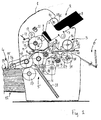
- Fig. 1 is a schematic, partially cut-away, side view of an example of an inserter according to the invention;
- Fig. 2 is a perspective, partially cut-away view of the drive structure of the inserter according to Fig. 1; and
- Fig. 3 is a perspective, partially cut-away view, seen at another angle, of the drive structure of the inserter according to Fig. 1.
- The inserter according to the example shown in the drawings has a
housing 1 in which anenvelope feeder 2, an envelope stuffing mechanism, a document feeder 4, a folder 5 and atray 6 for receiving completed mail pieces can be distinguished. - In an envelope holder 7 a
stack 8 of envelopes is held. A separating lip 9 andenvelope feeder roller 10 at the top end of theholder 2 define an envelope start position 11. - A set of
envelope transport rollers 12, guide rollers 13, 14 and aguide plate 15 extending along the envelope transport roller define an envelope transport path for transporting envelopes one by one from the envelope start position 11 to an inserting position in which, in Fig. 1, an envelope 16 is shown. The inserting position is determined by the positions of thetransport roller 12 and the most downstream guide roller 14 between which, in operation, theflap 17 of an envelope 16 in the inserting position is held, and byupper guides 18 andlower guides 19 between which thebody 20 of the envelope 16 to be filled is guided. Asensor 21 for sensing the passage of an envelope and aflap opener 17 are situated along the envelope transport path (Fig. 1). - In a document holder 22 (partially shown) a stack 23 of sheets is held. The holder and a
feeding roller 24 at the top end of the holder define a postalitem start position 25 from where transport of a document (or other postal item to be inserted in the envelope) starts when the inserter is in operation. A set oftransport rollers 26, a set of separatingrollers 27, abuckle folding chute 28, a set offolding rollers 29 and a pivotable guide plate 30 define a postal item transport path for transporting postal items one by one from the postalitem start position 25 to the inserting position until the postal item is inserted in the envelope 16. In Fig. 3, the transport rollers a26 are not visible, however an axle 32 via which thetransport rollers 26 are drivable and are suspended is visible in Fig. 3. - In Fig. 1, one
document 31 is shown in the postal item transport path in a position just before a fold is made in a folding nip between the transport rollers 26 (which also form folding rollers) and thefolding rollers 29. - The inserting position also extends between upper and lower
envelope closing rollers housing 1, theenvelope closing rollers tray 6. - For driving the rollers, the inserter according to the present example has a
single motor 37. To allow sequentially driving various functions of the inserter with thesame motor 37, a coupling is provided. For the sake of clarity, this coupling is first described with respect to the function of switching between driving envelope transport and postal item transport only. - The
motor 37 has adrive pulley 38 which is coupled to a pulley 39 on a main drive shaft 40 via atoothed drive belt 41. An postal itemdrive gear wheel 42 and an envelopedrive gear wheel 43 are fixedly mounted to the main drive shaft 40. - The postal item
drive gear wheel 42 permanently engages intermediate gear wheel 44, which, in turn, permanently engagesintermediate gear wheel 45. The intermediate gear wheels are rotatably suspended from an postal item drive rocker 46, which, in turn, is rotatably mounted on the main drive shaft 40 and carries an operating pawl 47 engaged by a postal item drive coupling control cam 48. A spring (not shown) keeps the operating pawl 47 of the postal item drive rocker 46 in engagement with the postal item drive coupling control cam 46. By rotating the postal item drive coupling control cam 48, the rocker 46 can be rotated between a coupled position in which theintermediate gear wheel 45 is in engagement with agear wheel 49 on a postalitem drive shaft 50 and an uncoupled position, in which theintermediate gear wheel 45, and thereby the main drive shaft 40, is uncoupled from thegear wheel 49 on the postalitem drive shaft 50. - A
pulley 51 fixedly mounted to the postalitem drive shaft 50 is coupled to apulley 52 fixedly mounted to thetransport roller axle 33 via atoothed drive belt 53 for driving the transport of postal items. - Thus, the postal item drive rocker 46 and the postal item
drive gear wheels motor 37 for driving the postal item transport path for transporting the postal items from the postalitem start position 25 to the inserting position 16 and for uncoupling themotor 37 when the postal item has been inserted in the envelope 16. The uncoupling of the postal itemdrive gear wheel 45 from thegear wheel 49 on the postalitem drive shaft 50 may for instance be carried out in response to detection of the trailing end of the postal item near the inserting position 16. The separating unit is not further described and may for instance be of a design as described inUS patent 5,362,037 . - The envelope
drive gear wheel 42 permanently engages anintermediate gear wheel 54 an areverse gear wheel 55, which in turn, permanently engages an intermediate gear wheel 56. Theintermediate gear wheels 54, 56 and thereverse gear wheel 55 are rotatably mounted to anenvelope drive rocker 57, which, in turn, is rotatably mounted to the main drive shaft 40 and carries an operating pawl 58 engaged by an envelope drivecoupling control cam 59. A spring (not shown) keeps the operating pawl 58 of therocker 57 in engagement with the envelope drivecoupling control cam 59. - By rotating the envelope drive
coupling control cam 59, theenvelope drive rocker 57 can be rotated between an envelope transport position and a flap moistening and closing position and a position in which none of theintermediate gear wheels 54 56 engages the gear wheel 60 on the envelope drive shaft 61. In the envelope transport position, theintermediate wheel 54 is in engagement with a gear wheel 60 fixedly mounted to an envelope drive shaft 61 and in which the envelope drive shaft 61 is driven to rotate in a sense of rotation indicated by arrow A by rotation of the main drive shaft 40 in a sense of rotation indicated by arrow B. In Figs. 2 and 3, the envelope drivecoupling control cam 59 is shown in a position keeping theenvelope drive rocker 57 in its flap moistening and closing position. In that position, the intermediate gear wheel 56 that is in driving engagement with thereverse gear wheel 55 is in engagement with the gear wheel 60 on the envelope drive shaft 61. In this operating condition, the rotation of the main drive shaft 40 in the sense of rotation B causes the envelope drive shaft 60 to rotate in sense of rotation indicated by an arrow C, which is opposite to the sense of rotation A for transporting envelopes. - A
drive pulley 62 fixedly mounted to the envelope drive shaft 61 is coupled to a anenvelope feed axle 63 carrying theenvelope feed rollers 10 via a toothed envelope drive belt 64 over thedrive pulley 62 and drivenpulley 65. The drivenpulley 65 is mounted to an envelope transport axle 66 carrying theenvelope transport rollers 12. A drive pulley 67 is mounted to the same envelope transport axle 66 for rotation together with the drivenpulley 65 and coupled to drivenpulleys 68, 70 via atoothed distribution belt 71. The driven pulley 68 is fixedly mounted to anenvelope closing axle 69 carrying an upper one of theenvelope closing rollers 34 and the drivenpulley 70 is fixedly coupled agear wheel 72 that is in driving engagement with agear wheel 73 fixedly mounted to theenvelope feed axle 63. - Thus, the
envelope drive rocker 57 and the envelopedrive gear wheels - It is observed that the
envelope feed rollers 10 should stop rotating after the feeding of an envelope is completed. This can for instance be achieved using a coupling controlled in response to signals from thesensor 21. It is also possible to provide a separate cam and coupling controlled thereby for coupling and uncoupling the envelope feed rollers to themotor 37. - The pulley 39 that is driven by the
motor 37 via thetoothed belt 41 is fixedly coupled to agear wheel 74 of which the teeth engage teeth of agear wheel 75 that is mounted on acam shaft 76 to which the cams 48, 56 are fixedly mounted. Thegear wheel 75 is coupled to thecam shaft 76 via a one-way clutch 77 that causes thegear wheel 75 to entrain thecam shaft 76 if thegear wheel 75 is rotated in a sense of rotation indicated by an arrow D and that freewheels if thegear wheel 75 is driven by thegear wheel 74 to rotate in the opposite sense of rotation. The pulley 39 and thegear wheel 74 are coupled to the main drive shaft 40 by a one-way clutch 78 that causes thegear wheel 74 to entrain the main drive shaft 40 if the pulley 39 and thegear wheel 74 are rotated in the sense of rotation B and that freewheels if the pulley 39 and thegear wheel 75 are rotated in the opposite sense of rotation. - If the
motor 37 is rotated in the sense of rotation indicated by an arrow E, the pulley 39 and thegear wheel 74 are rotated in the sense of rotation B so that the main drive shaft 40 is entrained while thegear wheel 75 is rotated in a sense of rotation opposite to the sense of rotation D. This causes the one-way clutch between thegear wheel 75 and thecam shaft 76 to freewheel, so that thecam shaft 76 is left stationary. Conversely, if themotor 37 is rotated in the opposite sense of rotation indicated by an arrow F, the pulley 39 and thegear wheel 74 are rotated in a sense opposite to the sense of rotation B so that the one-way clutch 78 between main drive shaft 40 and thegear wheel 74 freewheels, causing the main drive shaft to be left stationary. Thegear wheel 75 is then rotated in the sense of rotation D, which causes the one-way clutch 77 to engage and entrain thecam shaft 76. - Thus, the coupling control mechanism, formed by the
cams 48, 59, is driven via the two-way selector transmission formed by thegear wheels - In the present example, the selector transmission is arranged for driving the drive line in response to being driven in a first sense of rotation and for driving the coupling control mechanism in response to being driven in a second sense of rotation opposite to said first sense of rotation. This provides the advantage that simple switch gear is sufficient for switching between the first and the second operating condition. It is however also conceivable to provide other means for switching between the two operating conditions, such as electromagnetically operated couplings, an axially displaceable gear wheel or a differential drive having two output drive shafts with stoppers for selectively preventing rotation of one or, alternatively, the other of the output drive shafts.
- In present example, the selector transmission includes a first one-way clutch 78 via which the drive line is coupled to the
motor 37 and a second one-way clutch 77 via which thecoupling control mechanism 48, 59 is coupled to themotor 37. This allows a simple design with repeated use of standardized parts. It is however observed, that driving different structures in response to driving rotation in opposite directions can also be achieved in other manners, for example using a gear wheel that is suspended for moving between a position engaging a first driven gear wheel and a position engaging between another driven gear wheel in response to the driving torque. - That the coupling control mechanism includes
cams 48, 59 each having a cam surface arranged for engaging a control member 46, 47 of the coupling controlled thereby is advantageous for obtaining a simple design for transition of rotation of the motor into control operations and freedom of design with respect to the timing of operations is provided in a simple manner. - That the
cams 48, 59 are curve disks further contributes to the simplicity of design. - A further advantage of the use of cams is, that they allow to perform several control operations driven by the same motor. To this end, the inserter according to the present example is equipped with a plurality of cams.
- Apart from the cam 48 for controlling the coupling and uncoupling of the postal item drive line and the
cam 59 for controlling the sense of rotation of the envelope drive line, the inserter according to the present example also includesflap closing cams 79 andflap pressing cams 80. - The
flap closing cams 79 engage a roller 81 of envelope flap closing members in the form of arockers 82 carrying anaxle 83 on which a set offlap closing rollers 84 is mounted. In the drawings, theflap closing rollers 84 are shown in a position free from the envelope transport path. By rotating thecamshaft 76, theflap closing rollers 84 can be displaced from the shown position to a position on the opposite side of the envelope transport path and of the insert position, thereby pressingguide 19 away. If this is carried out while an envelope is positioned with a fold between the envelope flap and the envelope body is closely to the exit side of the trajectory along which theflap closing rollers 84 are displaced, the flap is pivoted towards a moistener 85 (Fig. 1). The flap can then be moistened and closed by transporting the envelope in a direction opposite to the direction in which it has arrived from the starting position 11. Finally the flap can be pressed against the envelope body for firm closing of the envelope by transporting the envelope towards the exit 36 and passing the envelope through a nip between therollers Dutch patent application 1 027 889 - Before the envelope flap can be pressed to the envelope body in the nip between the
rollers pressing cams 79 are provided, which are positioned on thecamshaft 76 for engaging rollers 86 ofrockers 87 that carry anaxle 88 to which thelower ones 35 of theenvelope pressing rollers rockers 88 under control of thepressing cams 79, thelower ones 35 of the envelope pressing rollers can be selectively moved between a transport position for transporting an envelope, in which a nip is formed between thepressing rollers roller 35. - To bring the
camshaft 76 accurately in the predefined positions and for avoiding accumulation of tolerance errors when the camshaft is repeatedly driven, an index wheel 89 is fixedly mounted to thecamshaft 76 and apositioning finger 90 carrying an index pawl 91 is mounted to the main drive shaft via a slip clutch 92. When themotor 37 started to rotate in the sense of rotation E, so that the main drive shaft 40 is driven and thegear wheel 75 freewheels on thecam shaft 76, thepositioning finger 90 is dragged along in the sense of rotation B of the main drive shaft 40 until it is lodged in an index recess on the circumference of the index wheel 89. Thecam shaft 76, which is then not controlled by themotor 37, is thereby reliable maintained in position. When themotor 37 is reversed into the sense of rotation F for driving thecamshaft 76, the driving torque is sufficient for pushing the pawl 91 of the positioning finger is pushed out of the indexing recess, but when themotor 37 is stopped, the indexing forces are sufficient for providing fine adjustments. - When the inserter according to the present example is in operation, the motor 7 is alternatingly rotated in the senses of rotation E and F over predetermined distances. To this end, the
motor 37 is preverably a stepper motor. - Operation the inserter according to the present example is further illustrated by table 1 in which the successive stages of operation and the control operations executed by the inserter are set forth.
Table 1 Stage Action Motor Envelope Drive Coupling Postal item drive Coupling Flap Closing Roller Pressing Roller I Operating inserter: see → Sense F 60° Forward (sense A) Retracted II Separating envelope and transporting envelope to insert position. Sense E to insert position II Operating inserter: see → Sense F 60° Off Engaged IV Separating, folding and transporting and inserting postal item. Sense E to insert position V Operating inserter: see → Sense F 60° Forward (sense A) Disengaged Pressing position VI Transporting filled envelope to flap pivoting position. Sense E to flap pivot position VII Operating inserter: see → Sense F 60° Reverse (sense C) Flap closing position VIII Transporting envelope so that flap closes. Sense E to flap closed position IX Operating inserter: see → Sense F 60° Forward (sense A) X Transporting envelope through pressing rollers to exit. Sense E to exit XI Operating inserter: see → Sense F 60° Off Released position - In each of the odd numbered stages, the camshaft is rotated over 60°, so that after one operating cycle during which a mail piece is prepared, the camshaft is rotated over 360°. However, depending on the design of the inserter another total number of stages is also conceivable. In the present inserter, it would in principle be possible to combine stages I and X, but the present sequence of stages is presently preferred, because all transport rollers are uncoupled when the inserter in not in operation, which facilitates cleaning and maintenance.
Claims (13)
- An inserter comprising:an envelope transport path (12-15) for transporting envelopes one by one from an envelope start position (11) to an inserting position (16);a postal item transport path (26-30) for transporting postal items one by one from a postal item start position (25) to the inserting position (16) until at least one of the transported postal item is inserted in the envelope;an exit (36) path (34-36) for transporting the envelope with the at least one inserted postal item therein from the inserting position (16) to an exit (36);a motor (37);at least one drive line between the motor (37) and at least one of the paths for driving transport along that at least one of the paths;at least one coupling (42, 46-47, 49; 43, 54-58, 60) included in the at least one drive line;a coupling control mechanism (48, 59, 76) connected for engaging a control member (47; 58) of the coupling (42, 45-47, 49; 43, 54-58, 60); andan at least two-way selector transmission (74, 75, 77, 78) for driving the at least one drive line if the selector transmission (74, 75, 77, 78) is in a first operating condition and for driving the coupling control mechanism (48, 59, 76) for operating the at least one coupling (42, 45-47, 49; 43, 54-58, 60) if the selector transmission (74, 75, 77, 78) is in a second operating condition.
- An inserter system according to claim 1, wherein the selector transmission (74, 75, 77, 78) is arranged for driving the drive line in response to being driven in a first sense of rotation (E) and for driving the coupling control mechanism (48, 59, 76) in response to being driven in a second sense of rotation (F) opposite to said first sense of rotation.
- An inserter according to claim 2, wherein the selector transmission (74, 75, 77, 78) comprises a first one-way clutch (78) via which the drive line is coupled to the motor (37), the first one-way clutch (78) being mounted for driving in response to rotation of the motor (37) in the first sense of rotation (E) and a second one-way clutch (77) via which the coupling control mechanism (48, 59, 76) is coupled to the motor (37), the second one-way clutch (77) being mounted for driving in response to rotation of the motor (37) in the second sense of rotation (F).
- An inserter according to any one of the preceding claims, wherein the coupling control mechanism (48, 59, 76) includes at least one cam (48; 59) having a cam surface arranged for engaging a control member (47; 58) of the at least one coupling (42, 45-47, 49; 43, 54-58, 60).
- An inserter according to claim 4, wherein the at least one cam is a curve disk (47; 58).
- An inserter according to claim 4 or 5, wherein a plurality of cams (47; 58; 79; 80) are provided.
- An inserter according to claim 6, wherein at least one of the cams (79) engages an envelope flap closing control member (81).
- An inserter according to claim 6 or 7, wherein at least one of the cams (80) engages a carrier control member (86) for selectively moving a transport roller (35) between a transport position for transporting a postal item or an envelope and a retracted position.
- An inserter according to any one of the preceding claims, wherein the coupling (42, 45-47, 49; 43, 54-58, 60) is adapted for selectively coupling (42, 45-47, 49; 43, 54-58, 60) the motor (37) to the drive line or at least one of the drive lines and uncoupling (42, 45-47, 49; 43, 54-58, 60) the motor (37) from the drive line or at least one of the drive lines.
- An inserter according to any one of the preceding claims, wherein the coupling (42, 45-47, 49; 43, 54-58, 60) is a reversing coupling (42, 45-47, 49; 43, 54-58, 60).
- A method for inserting postal items into envelopes using an inserter for inserting postal items into envelopes, comprising, for each envelope:transporting the envelope from an envelope start position (11) to an inserting position (16);transporting at least one of the postal items (31) from a postal item start position (25) to the inserting position (16) until the at least one postal item (31) is inserted in the envelope (16); andtransporting the envelope from the inserting position (16) to an exit (36);wherein the transportation is driven by a motor (37) via at least one coupling (42, 45-47, 49; 43, 54-58, 60);wherein the coupling (42, 45-47, 49; 43, 54-58, 60) or at least one of the couplings (42, 45-47, 49; 43, 54-58, 60) is operated for controlling transportation driven by said motor (37); andwherein the operation of controlling said coupling (42, 45-47, 49; 43, 54-58, 60) is driven by said motor (37).
- A method according to claim 11, wherein the transporting of the envelopes (16) and of the postal items (31) is driven in response to the motor (37) rotating in a first sense of rotation (E) and wherein the operation of controlling said coupling (42, 45-47, 49; 43, 54-58, 60) is driven in response to the motor (37) rotating in a second sense of rotation (F) opposite to said first sense of rotation.
- A method according to claim 11 or 12, wherein the coupling (42, 45-47, 49; 43, 54-58, 60) and uncoupling (42, 45-47, 49; 43, 54-58, 60) is operated by driving movement of a cam (48, 59) engaging a control member (47, 58) of a coupling (42, 45-47, 49; 43, 54-58, 60).
Priority Applications (3)
| Application Number | Priority Date | Filing Date | Title |
|---|---|---|---|
| DE602005019313T DE602005019313D1 (en) | 2005-12-31 | 2005-12-31 | Inserter with motor and controllable clutch |
| EP05078063A EP1803585B1 (en) | 2005-12-31 | 2005-12-31 | Inserter having a motor and a controlled coupling |
| US11/617,950 US20070164497A1 (en) | 2005-12-31 | 2006-12-29 | Inserter and method for inserting postal items into envelopes |
Applications Claiming Priority (1)
| Application Number | Priority Date | Filing Date | Title |
|---|---|---|---|
| EP05078063A EP1803585B1 (en) | 2005-12-31 | 2005-12-31 | Inserter having a motor and a controlled coupling |
Publications (2)
| Publication Number | Publication Date |
|---|---|
| EP1803585A1 true EP1803585A1 (en) | 2007-07-04 |
| EP1803585B1 EP1803585B1 (en) | 2010-02-10 |
Family
ID=36591327
Family Applications (1)
| Application Number | Title | Priority Date | Filing Date |
|---|---|---|---|
| EP05078063A Expired - Lifetime EP1803585B1 (en) | 2005-12-31 | 2005-12-31 | Inserter having a motor and a controlled coupling |
Country Status (3)
| Country | Link |
|---|---|
| US (1) | US20070164497A1 (en) |
| EP (1) | EP1803585B1 (en) |
| DE (1) | DE602005019313D1 (en) |
Cited By (1)
| Publication number | Priority date | Publication date | Assignee | Title |
|---|---|---|---|---|
| EP1935815A3 (en) * | 2006-12-21 | 2010-02-10 | Pitney Bowes Limited | Selective drive mechanism |
Families Citing this family (2)
| Publication number | Priority date | Publication date | Assignee | Title |
|---|---|---|---|---|
| EP2106926B1 (en) * | 2008-04-04 | 2010-11-10 | Neopost Technologies | Apparatus and method for moistening envelope flaps |
| US12129145B2 (en) * | 2021-05-27 | 2024-10-29 | Ricoh Company, Ltd. | Enclosing apparatus and image forming system |
Citations (9)
| Publication number | Priority date | Publication date | Assignee | Title |
|---|---|---|---|---|
| US4924652A (en) * | 1988-07-27 | 1990-05-15 | Societe Anonyme Dite: Alcatel Satmam | Integrated office machine for folding mail and inserting it into envelopes |
| US4995600A (en) * | 1988-01-29 | 1991-02-26 | Societe Anonyme Dite: Alcatel Satman | General-purpose folding machine |
| EP0504114A1 (en) * | 1991-03-12 | 1992-09-16 | Kern Ag | Device for inserting documents in envelope |
| WO1994008882A1 (en) * | 1992-10-19 | 1994-04-28 | Karl Zechner | Buckle folding machine |
| US5362037A (en) | 1990-02-09 | 1994-11-08 | Hadewe B.V. | Method of, and apparatus for, delivering flat articles one by one from a stack of such articles |
| DE10129573C1 (en) * | 2001-06-20 | 2002-06-06 | Pitney Bowes Technologies Gmbh | Mail handling machine has envelope filling station for insertion of individual sheets or sheet sets in open envelopes |
| GB2386360A (en) * | 2002-03-13 | 2003-09-17 | Pitney Bowes Ltd | Envelope sealing apparatus |
| EP1550628A1 (en) * | 2003-12-31 | 2005-07-06 | Neopost S.A. | Method and apparatus for processing sheets of different sizes to a mail item |
| NL1027889C2 (en) | 2004-12-24 | 2006-06-27 | Neopost Sa | Envelope closing device and method for closing an envelope. |
Family Cites Families (4)
| Publication number | Priority date | Publication date | Assignee | Title |
|---|---|---|---|---|
| JPS5971573A (en) * | 1982-10-18 | 1984-04-23 | Toshiba Corp | Automatic transaction system |
| JP3281895B2 (en) * | 1996-02-08 | 2002-05-13 | プリンサーター コーポレイション | Mail handling system and control method thereof |
| US7152386B2 (en) * | 2004-01-08 | 2006-12-26 | Pitney Bowes Deutschland Gmbh. | Envelope-filling machine |
| FR2873106A1 (en) * | 2004-07-13 | 2006-01-20 | Secap Soc Par Actions Simplifi | MECHANICAL DEVICE FOR RECEIVING DOCUMENTS |
-
2005
- 2005-12-31 EP EP05078063A patent/EP1803585B1/en not_active Expired - Lifetime
- 2005-12-31 DE DE602005019313T patent/DE602005019313D1/en not_active Expired - Lifetime
-
2006
- 2006-12-29 US US11/617,950 patent/US20070164497A1/en not_active Abandoned
Patent Citations (9)
| Publication number | Priority date | Publication date | Assignee | Title |
|---|---|---|---|---|
| US4995600A (en) * | 1988-01-29 | 1991-02-26 | Societe Anonyme Dite: Alcatel Satman | General-purpose folding machine |
| US4924652A (en) * | 1988-07-27 | 1990-05-15 | Societe Anonyme Dite: Alcatel Satmam | Integrated office machine for folding mail and inserting it into envelopes |
| US5362037A (en) | 1990-02-09 | 1994-11-08 | Hadewe B.V. | Method of, and apparatus for, delivering flat articles one by one from a stack of such articles |
| EP0504114A1 (en) * | 1991-03-12 | 1992-09-16 | Kern Ag | Device for inserting documents in envelope |
| WO1994008882A1 (en) * | 1992-10-19 | 1994-04-28 | Karl Zechner | Buckle folding machine |
| DE10129573C1 (en) * | 2001-06-20 | 2002-06-06 | Pitney Bowes Technologies Gmbh | Mail handling machine has envelope filling station for insertion of individual sheets or sheet sets in open envelopes |
| GB2386360A (en) * | 2002-03-13 | 2003-09-17 | Pitney Bowes Ltd | Envelope sealing apparatus |
| EP1550628A1 (en) * | 2003-12-31 | 2005-07-06 | Neopost S.A. | Method and apparatus for processing sheets of different sizes to a mail item |
| NL1027889C2 (en) | 2004-12-24 | 2006-06-27 | Neopost Sa | Envelope closing device and method for closing an envelope. |
Cited By (2)
| Publication number | Priority date | Publication date | Assignee | Title |
|---|---|---|---|---|
| EP1935815A3 (en) * | 2006-12-21 | 2010-02-10 | Pitney Bowes Limited | Selective drive mechanism |
| US7819395B2 (en) | 2006-12-21 | 2010-10-26 | Pitney Bowes Ltd. | Selective drive mechanism |
Also Published As
| Publication number | Publication date |
|---|---|
| DE602005019313D1 (en) | 2010-03-25 |
| US20070164497A1 (en) | 2007-07-19 |
| EP1803585B1 (en) | 2010-02-10 |
Similar Documents
| Publication | Publication Date | Title |
|---|---|---|
| US5125214A (en) | Inserter station for envelope inserting | |
| US5029832A (en) | In-line rotary inserter | |
| EP2433811B1 (en) | Envelope transport and insertion machine | |
| US3936993A (en) | Envelope filling machine | |
| US7594652B2 (en) | Separation system | |
| JPH05504106A (en) | Device for inserting contents into envelopes | |
| EP2123474B1 (en) | Method and an apparatus for inserting a postal item into an envelope | |
| US7819395B2 (en) | Selective drive mechanism | |
| US5820275A (en) | Printer multi-function drive train apparatus and method | |
| EP1803585B1 (en) | Inserter having a motor and a controlled coupling | |
| US5211384A (en) | Inserter with diverter for faulty members | |
| US6038835A (en) | Apparatus and method for inserting documents into envelopes | |
| US5901953A (en) | Diverter apparatus and method for sheets or envelopes | |
| US5125642A (en) | Feeder module with thickness detection | |
| US5154404A (en) | Jam detector for inserter | |
| CN112830321A (en) | A signature acceleration device of a high-speed roller type automatic collating machine and its collating machine | |
| US5125215A (en) | Envelope flap opener | |
| US20040035528A1 (en) | Envelope sealing apparatus | |
| KR100989050B1 (en) | Mail sealer | |
| US5476253A (en) | Paper slip transport and stack unit | |
| CN109422124A (en) | Stack device and processing unit | |
| JPH08104457A (en) | Paper sorter and paper aligner | |
| CN204810377U (en) | Scanning unit with paper correction | |
| US20060151941A1 (en) | Speed control for sheet handling apparatus | |
| JPS6322443A (en) | Automatic sheet feeding device |
Legal Events
| Date | Code | Title | Description |
|---|---|---|---|
| PUAI | Public reference made under article 153(3) epc to a published international application that has entered the european phase |
Free format text: ORIGINAL CODE: 0009012 |
|
| AK | Designated contracting states |
Kind code of ref document: A1 Designated state(s): AT BE BG CH CY CZ DE DK EE ES FI FR GB GR HU IE IS IT LI LT LU LV MC NL PL PT RO SE SI SK TR |
|
| AX | Request for extension of the european patent |
Extension state: AL BA HR MK YU |
|
| 17P | Request for examination filed |
Effective date: 20070817 |
|
| 17Q | First examination report despatched |
Effective date: 20070924 |
|
| AKX | Designation fees paid |
Designated state(s): DE FR GB |
|
| GRAP | Despatch of communication of intention to grant a patent |
Free format text: ORIGINAL CODE: EPIDOSNIGR1 |
|
| GRAS | Grant fee paid |
Free format text: ORIGINAL CODE: EPIDOSNIGR3 |
|
| GRAA | (expected) grant |
Free format text: ORIGINAL CODE: 0009210 |
|
| AK | Designated contracting states |
Kind code of ref document: B1 Designated state(s): DE FR GB |
|
| REG | Reference to a national code |
Ref country code: GB Ref legal event code: FG4D |
|
| REF | Corresponds to: |
Ref document number: 602005019313 Country of ref document: DE Date of ref document: 20100325 Kind code of ref document: P |
|
| PLBE | No opposition filed within time limit |
Free format text: ORIGINAL CODE: 0009261 |
|
| STAA | Information on the status of an ep patent application or granted ep patent |
Free format text: STATUS: NO OPPOSITION FILED WITHIN TIME LIMIT |
|
| 26N | No opposition filed |
Effective date: 20101111 |
|
| PGFP | Annual fee paid to national office [announced via postgrant information from national office to epo] |
Ref country code: GB Payment date: 20101221 Year of fee payment: 6 |
|
| PGFP | Annual fee paid to national office [announced via postgrant information from national office to epo] |
Ref country code: FR Payment date: 20120105 Year of fee payment: 7 |
|
| PGFP | Annual fee paid to national office [announced via postgrant information from national office to epo] |
Ref country code: DE Payment date: 20111222 Year of fee payment: 7 |
|
| GBPC | Gb: european patent ceased through non-payment of renewal fee |
Effective date: 20121231 |
|
| REG | Reference to a national code |
Ref country code: FR Ref legal event code: ST Effective date: 20130830 |
|
| REG | Reference to a national code |
Ref country code: DE Ref legal event code: R119 Ref document number: 602005019313 Country of ref document: DE Effective date: 20130702 |
|
| PG25 | Lapsed in a contracting state [announced via postgrant information from national office to epo] |
Ref country code: DE Free format text: LAPSE BECAUSE OF NON-PAYMENT OF DUE FEES Effective date: 20130702 |
|
| PG25 | Lapsed in a contracting state [announced via postgrant information from national office to epo] |
Ref country code: GB Free format text: LAPSE BECAUSE OF NON-PAYMENT OF DUE FEES Effective date: 20121231 Ref country code: FR Free format text: LAPSE BECAUSE OF NON-PAYMENT OF DUE FEES Effective date: 20130102 |