EP1800876B1 - A device for radiation drying - Google Patents
A device for radiation drying Download PDFInfo
- Publication number
- EP1800876B1 EP1800876B1 EP05425907A EP05425907A EP1800876B1 EP 1800876 B1 EP1800876 B1 EP 1800876B1 EP 05425907 A EP05425907 A EP 05425907A EP 05425907 A EP05425907 A EP 05425907A EP 1800876 B1 EP1800876 B1 EP 1800876B1
- Authority
- EP
- European Patent Office
- Prior art keywords
- plate
- lamp
- articles
- radiation
- window
- Prior art date
- Legal status (The legal status is an assumption and is not a legal conclusion. Google has not performed a legal analysis and makes no representation as to the accuracy of the status listed.)
- Expired - Lifetime
Links
Images



Classifications
-
- B—PERFORMING OPERATIONS; TRANSPORTING
- B41—PRINTING; LINING MACHINES; TYPEWRITERS; STAMPS
- B41J—TYPEWRITERS; SELECTIVE PRINTING MECHANISMS, i.e. MECHANISMS PRINTING OTHERWISE THAN FROM A FORME; CORRECTION OF TYPOGRAPHICAL ERRORS
- B41J11/00—Devices or arrangements of selective printing mechanisms, e.g. ink-jet printers or thermal printers, for supporting or handling copy material in sheet or web form
- B41J11/0015—Devices or arrangements of selective printing mechanisms, e.g. ink-jet printers or thermal printers, for supporting or handling copy material in sheet or web form for treating before, during or after printing or for uniform coating or laminating the copy material before or after printing
- B41J11/002—Curing or drying the ink on the copy materials, e.g. by heating or irradiating
-
- B—PERFORMING OPERATIONS; TRANSPORTING
- B41—PRINTING; LINING MACHINES; TYPEWRITERS; STAMPS
- B41J—TYPEWRITERS; SELECTIVE PRINTING MECHANISMS, i.e. MECHANISMS PRINTING OTHERWISE THAN FROM A FORME; CORRECTION OF TYPOGRAPHICAL ERRORS
- B41J11/00—Devices or arrangements of selective printing mechanisms, e.g. ink-jet printers or thermal printers, for supporting or handling copy material in sheet or web form
- B41J11/0015—Devices or arrangements of selective printing mechanisms, e.g. ink-jet printers or thermal printers, for supporting or handling copy material in sheet or web form for treating before, during or after printing or for uniform coating or laminating the copy material before or after printing
- B41J11/002—Curing or drying the ink on the copy materials, e.g. by heating or irradiating
- B41J11/0021—Curing or drying the ink on the copy materials, e.g. by heating or irradiating using irradiation
- B41J11/00214—Curing or drying the ink on the copy materials, e.g. by heating or irradiating using irradiation using UV radiation
-
- B—PERFORMING OPERATIONS; TRANSPORTING
- B41—PRINTING; LINING MACHINES; TYPEWRITERS; STAMPS
- B41J—TYPEWRITERS; SELECTIVE PRINTING MECHANISMS, i.e. MECHANISMS PRINTING OTHERWISE THAN FROM A FORME; CORRECTION OF TYPOGRAPHICAL ERRORS
- B41J11/00—Devices or arrangements of selective printing mechanisms, e.g. ink-jet printers or thermal printers, for supporting or handling copy material in sheet or web form
- B41J11/0015—Devices or arrangements of selective printing mechanisms, e.g. ink-jet printers or thermal printers, for supporting or handling copy material in sheet or web form for treating before, during or after printing or for uniform coating or laminating the copy material before or after printing
- B41J11/002—Curing or drying the ink on the copy materials, e.g. by heating or irradiating
- B41J11/0021—Curing or drying the ink on the copy materials, e.g. by heating or irradiating using irradiation
- B41J11/00218—Constructional details of the irradiation means, e.g. radiation source attached to reciprocating print head assembly or shutter means provided on the radiation source
Definitions
- the present invention relates to an ink-jet printing apparatus.
- the present invention specifically applies to the step of drying printed articles in which specific inks are used.
- the present invention relates to ultraviolet-radiation (UV) drying devices.
- UV ultraviolet-radiation
- the ink-jet printing apparatus presently on the market are provided with print heads whose task is to pick up the ink from a tank and dispose it at a predetermined speed onto the article to be printed in an amount and following modalities depending on the printing operation to be carried out.
- UV-radiation technology is increasingly more often used in all sectors of the graphic industry and in the sectors involving quality printing processes to be made quickly and in successive passages.
- the final article can be immediately used or piled up for storage and/or transport.
- the process for example applies when paperboard and corrugated cardboard are to be printed and includes printing on packages for medical and food articles, labels, plastic materials, sheet metals or safety cards such as banknotes or credit cards.
- Inks drying through exposure to UV radiation consist of liquid components such as polyfunctional epoxy resins containing reactive acrylates, additives, colouring agents and photocatalysts that cross-link to form a dry and hard film under the action of a UV radiation source.
- UV lamps There are different types of UV lamps; the two most used ones are the high-pressure mercury-arc lamps and low pressure lamps.
- UV lamps of the high pressure and mercury-arc type are generally built in the form of a tube and are not very long.
- the lamps are provided with a cooling plant surrounding them and adapted to draw the excess heat generated by the lamps themselves. In this way the lifetime of the lamp can be increased.
- the lamps are closed by an opening screen preventing the UV radiation from being reflected to the outside, which would cause even serious trouble to the operators and would affect the performance of the print heads.
- the emitted UV radiation impinges on the print heads for an excessive period of time, it can dry the nozzles thereby impairing the print quality, and sometimes even damaging the heads themselves in an irreparable manner.
- this solution is weakly efficient since an air flow can hardly reach all points of the overheated surfaces.
- UV-radiation drying devices of the above described type are characterised by an important bulkiness, exactly due to the sizes of the cooling plant.
- use of an air flow involves the presence of fans of an important diameter.
- the air flow interacts with the ink jet emitted from the heads and impairs the print quality and accuracy.
- the fans generate a strong noise resulting in trouble for the operators working in the vicinity of said fans.
- the apparatus includes moving work, conveyor means for the moving work, an assembly including ultraviolet producing source and reflector partially encasing the ultraviolet producing source and adapted to reflect the radiant energy from the ultraviolet producing source toward the moving work, closable shutter means for blocking the radiant energy from the ultraviolet producing source from impinging upon the moving work when the operation of the system is temporarily interrupted.
- the reflector, the shutter means, as well as the conveyor, are provided with a plurality of spaced heat pipes contiguously affixed thereto and adapted to cool these elements.
- a device for radiation drying comprising at least one lamp 2, preferably but not exclusively a UV light lamp, has been generally identified by reference numeral 1.
- two of said devices 1 are mounted on an ink-jet printing apparatus electronically controlled by a processor.
- a plurality of articles 3 is laid on a support or tray 4 driven in relative motion with respect to the drying device 1.
- the support 4 is fixed, whereas the whole drying device 1 is slidably movable along a printing and drying direction "F".
- the support 4 is slidably movable along the printing and drying direction "F" and the drying device 1 is mounted on a fixed supporting structure (not shown).
- the support 4 defines a reciprocating motion along the direction "F” so as to repeatedly bring the articles 3 below the print heads and the lamps 2, to enable printing, i.e. laying of the ink, and full drying of the article 3 in several steps.
- the lamps 2 are disposed with the respective main extension axis at right angles to the direction "F". Said lamps 2 are enclosed into respective lamp-holding boxes 5 inside which, in addition, a cooling liquid flows to remove the excess heat generated by the lamps 2. To this aim, lamps 2 are fully surrounded by, and/or dipped in this liquid.
- the cooling liquid consists of water.
- the drying device 1 further comprises a plate-like structure 6 put under each lamp 2.
- This plate-like structure has a base 6a of essentially elongated rectangular shape and flaps 6b along the major sides which are folded in a "C" configuration.
- the plate-like structure 6 has the function of closing each lamp-holding box 5 at the lower part thereof.
- the lamp-holding boxes 5 are represented spaced apart from the supporting structure 6 for the sake of clarity. Actually, a lower end of each box 5 lies between the two C-folded sides preventing lateral escape of the UV radiation.
- the lamp 2 is therefore very close to the articles 3 to be dried, so that the emitted radiation can reach the articles 3 almost completely and the amount of power lost is minimised.
- a window 7 is formed on the base 6a of each supporting structure 6, at the region along which the support 4 with the articles 3 carried thereon travels, so that the UV light beam is enabled to impinge on the articles 3 themselves.
- the shape of the window 7 essentially depends on the shape of the articles 3. In the embodiment shown, in which articles 3 consist of discs, such as CD's and DVD's, the window 7 is substantially of rectangular shape.
- the window 7 is provided with an opening screen 8.
- This opening screen 8 comprises at least one movable wall.
- the screen 8 comprises two movable walls 9 of elongated rectangular shape. These walls are shiftable close to or away from each other.
- the walls 9 are movable between a first position at which the window 7 is closed and the UV light beam is intercepted, and a second position at which the window 7 is open and the UV light beam can impinge on the underlying articles 3.
- the movable walls 9 slide along a straight bar 10 and on the base 6a of the plate-like supporting structure 6. Movement of said walls is preferably ensured by a respective linear actuator 11, of the pneumatic type for example.
- the drying device 1 advantageously comprises a liquid cooling plant 12 integrated into the movable walls 9 of the screen 8. In fact, at the inside of each wall 9 ducts 13 are formed along which the cooling liquid flows.
- the ducts 13 consist of a first hole 14 and a second hole 15; they are both through holes and are parallel to each other.
- Said holes 14, 15 extend from a first end 9a of each wall to a second end 9b, opposite to the first one 9a.
- a third hole 16 is made perpendicular to the first 14 and second 15 holes.
- the third hole 16 passes through the first hole 14 and opens into the second hole 15.
- the third hole 16 is made close to the second end 9b of each wall 9.
- the outlet of the third hole 16 and the outlets of the first 14 and second 15 holes in the vicinity of the second end 9b of each wall 9 are closed by means of plugs 17. In this manner, a U-shaped pipe coil is obtained.
- the pipe coil could in any case have a different shape, depending each time on the specific requirements.
- pipes 18 Connected to the outlets of the first 14 and second 15 holes are pipes 18 defining the coil delivery side and return side and they are connected to other components of the cooling plant not shown, such as a radiator and a pump for example.
- the cooling plant further comprises a heat exchanger 19 placed under the base 6a of each plate-like structure 6 and disposed in side by side relationship with the window 7.
- the heat exchanger 19 comprises a plate 20 of substantially rectangular shape. A face 20a of each plate 20 is put into contact with the base 6a of the supporting structure 6.
- ducts 21 Formed within the plate 20 are ducts 21 similar to those formed in each movable wall 9.
- said ducts 21 have a first 22 and a second 23 holes, consisting both of mutually parallel through holes, and a third hole 24 perpendicular to the first 22 and second 23 holes.
- the third hole 24 passes through the first hole 22 and opens into the second one 23.
- the outlets of the third hole 24 and those of the first hole 22 and the second hole 23 placed at one end 20b of plate 20 are closed by plugs 17.
- plugs 17 In this manner a U-shaped pipe coil is obtained that is quite similar to that of the movable walls 9.
- the cooling liquid therefore runs in the ducts 13 of the movable walls 9 and in the ducts 21 of the heat exchanger 19, drawing the heat produced by the UV light beam impacting against the metal surfaces of the drying device 1.
- the cooling liquid typically consists of water. However, also other types of liquids can be used. In fact, should a power increase be required in the UV lamps, there would be too much heat to be removed and water would not be sufficient any longer. In this case, liquids characterised by a boiling temperature higher than 100°C are used.
- the water can be maintained to a higher pressure than the atmospheric one so as to increase its boiling temperature.
- the drying device 1 is advantageously mounted on an ink-jet printing apparatus 25 to print articles 3 preferably but not exclusively made of plastic material ( Fig. 3 ) such as CD's or DVD's.
- apparatus 25 comprises two drying devices 1 both mounted on a base 26 of the apparatus 25 itself.
- This printing apparatus 25 comprises at least one print head 27a, 27b for each colour used.
- the printing apparatus 25 involves a four-colour process and therefore on the whole uses five inks of different colours (black, magenta, cyan, yellow and a colour designed to constitute a background such as white). It is therefore possible for an ink to feed more than one head.
- the present printing apparatus 25 comprises six main print heads 27a for a four-colour printing process and two further auxiliary heads 27b for printing of the background.
- the printing apparatus 25 further comprises an ink-containing tank 28 connected to a metering device 30 by means of a regulating valve 29.
- the metering device 30 is connected to the print head or heads 27a, 27b.
- the printing apparatus 25 further comprises a cleaning device 31 for the print heads 27a, 27b.
- This device 31 comprises a plurality of suction openings 32 associated with each head 27a, 27b.
- the suction openings 32 are mounted on supporting plates 33.
- the plates 33 are movable in a substantially vertical direction so that the suction openings 32 can be reached by the heads 27a, 27b.
- the articles 3 to be printed lie on a support 4 movable in a reciprocating motion in the printing direction "F".
- the support 4 is positioned along a central straight guide 34 extending in the longitudinal extension of the printing apparatus 25 and is fastened to the base 26.
- the support 4 is moved by a suitable linear motor (not shown).
- the print heads 27a, 27b are housed on a carriage 35 movable in a direction "G" perpendicular to the printing direction "F” along suitable parallel slides 36.
- all heads 27a, 27b are aligned in parallel to the printing direction "F".
- the main heads 27a intended for a four-colour printing process are out of alignment relative to the auxiliary heads 27b reserved for printing of the background so that, during each passage of articles 3 under the heads 27a, 27b, the background-ink band is translated relative to that of the coloured ink.
- the coloured-ink band does not fully cover the background-ink band, so as to prevent the coloured ink from being directly laid on articles 3 without previous laying of the background.
- the printing apparatus 25 comprises two UV light drying devices 1. Said devices 1 are mounted on the base 26 of the printing apparatus 25 and in particular they are mounted under the carriage 35 housing the heads 27.
- the plate-like structure 6 of each of the devices 2 is integral with the base 26 and placed on the support 4 while the lamp-holding box 5 is integral with the carriage 35 and moves with the latter along the direction "G" perpendicular to the printing direction "F".
- the box 5 therefore slides on the plate-like structure 6 and between the C-folded flaps 6b.
- the lamp 2 follows the heads 27a, 27b so as to keep its central position emitting the maximum radiation amount exactly on the just printed region to be dried.
- the box 5 is fixed and integral with the plate-like structure 6 mounted on the base 26.
- the central portion of lamp 2 is long enough to cover the whole path of the heads 27a, 27b in the direction "G" perpendicular to the printing direction "F".
- the first drying device 1 is mounted between the main heads 27a and the auxiliary heads 27b.
- the function of this device is mainly to dry the background ink layer disposed on articles 3.
- the second device drying 1 is mounted to a position opposite to the first device with respect to the main heads 27a and its task is to dry the coloured ink layer laid on the background.
- Articles 3 are loaded and unloaded from support 4 by suitable handling means 38 that preferably comprises a movable frame 39.
- the movable frame 39 is made up of two parallel bars 40 joined together by a plurality of crosspieces 41. Disposed along said bars 40 is suitable grip means 42 preferably although not exclusively consisting of suction outlets.
- the printing apparatus 25 further comprises a first loading conveyor belt 43 connected to a first loading magazine 44 containing the articles 3 to be printed, i.e. on which ink is to be laid, and a second unloading conveyor belt 45 connected to a second unloading magazine 46 into which the already printed articles 3 are stored.
- Extending between the loading conveyor belt 43 and the unloading conveyor belt 45 is said linear guide 34 so that the support 4 can be brought to an intermediate position between the loading conveyor belt 43 and the unloading conveyor belt 45.
- Said frame 39 is movable in a horizontal direction between a first position, at which one of the bars 40 is in superposed relationship with the loading belt 43 and a second position at which the other bar 40 is in superposed relationship with the unloading belt 45.
- the frame 39 is also movable in a vertical direction between a raised position and a lowered position.
- the frame 39 takes up the first horizontal position, so that one bar 40 is on the articles 3 to be printed and disposed on the loading belt 43 and the other bar 40 is on the printed articles 3 laid on the support 4.
- the movable frame 39 moves downwards and the grip means 42 is actuated to grasp the articles 3 that are raised simultaneously with frame 39.
- the frame 39 is shifted to the second horizontal position at which the bar 40 carrying the articles 3 to be printed is over the support 4, and the bar 40 carrying the printed articles 3 is over the unloading conveyor belt 45.
- Said handling means 38 further comprises a cross structure 47 ensuring connection between the magazines 44, 46 and the conveyor belts 43, 45.
- the cross structure 47 is provided with grip means (not shown in the figures) that generally consists of suction outlets.
- the cross structure 47 is movable in a vertical direction and is driven in rotation about its substantially vertical axis due to a respective motor, not shown.
- the cross structure 47 is provided with four arms 48 and carries out loading and unloading of the articles onto and from the conveyor belts 43, 45. First of all, the cross structure 47 by the grip means, grasps a printed article 3 from the unloading conveyor belt 45 and an article to be printed 3 from the loading magazine 44.
- the cross structure 47 releases the article to be printed 3 onto the loading conveyor belt 43 and the printed article 3 into the unloading magazine 49. Simultaneously, the cross structure 47 grasps a printed article 3 again from the unloading conveyor belt 45 and an article to be printed 3 from the loading magazine 44.
- the loading magazine 44 and unloading magazine 46 each comprise a revolving plate 49 provided with a plurality of seats adapted to carry the articles 3.
- said articles 3. consist of optically readable discs such as CD's or DVD's and the necessary seats to carry them are defined by vertical rods 50.
- the present invention achieves the intended purposes and has important advantages.
- the liquid cooling plant 12 mounted in the drying device 1 is more efficient in removing the heat generated by an interaction of the UV light beam with the metal walls. Therefore, the UV light lamps can be maintained switched on, the screen walls being closed, also during short servicing interventions, without being obliged to actuate them again and wait for heating of same before restarting working. Therefore, the time and amount of the radiation impinging on the print heads can be reduced, which will result in an increase in the lifetime of the heads and an improvement in the print quality.
- the liquid cooling plant 12 enables use of fans of big sizes to be avoided for generating the necessary air flow.
- the cooling plant 12 is therefore more compact and consequently the drying device 1 and printing apparatus 25 on which it is mounted are characterised by a reduced bulkiness. Since there is no air flow impinging on the ink emitted from the heads, the print quality is excellent. Furthermore, due to the absence of fans, the drying device 1 is much more noiseless and the trouble of the operators working in the vicinity of the printing apparatus 25 is practically eliminated.
- the device 1 is very versatile, as it is adapted for different operating conditions.
Landscapes
- Health & Medical Sciences (AREA)
- General Health & Medical Sciences (AREA)
- Toxicology (AREA)
- Drying Of Solid Materials (AREA)
- Screen Printers (AREA)
Abstract
Description
- The present invention relates to an ink-jet printing apparatus.
- In particular, the present invention specifically applies to the step of drying printed articles in which specific inks are used.
- Preferably, the present invention relates to ultraviolet-radiation (UV) drying devices.
- It is known that a great number of the ink-jet printing apparatus use UV-radiation devices for drying articles on which ink has been laid.
- The ink-jet printing apparatus presently on the market are provided with print heads whose task is to pick up the ink from a tank and dispose it at a predetermined speed onto the article to be printed in an amount and following modalities depending on the printing operation to be carried out.
- The UV-radiation technology is increasingly more often used in all sectors of the graphic industry and in the sectors involving quality printing processes to be made quickly and in successive passages. There is a widespread use of UV light lamps as a drying device in a wide range of fields including polymerisation of the printing inks and coatings, applications for wood, plastic, paper and glass finish or for metal decorations, optical fibres, CD or DVD production and electronic devices.
- Due to quick drying and durable brightness of the printed ink, the final article can be immediately used or piled up for storage and/or transport.
- The process for example applies when paperboard and corrugated cardboard are to be printed and includes printing on packages for medical and food articles, labels, plastic materials, sheet metals or safety cards such as banknotes or credit cards.
- Inks drying through exposure to UV radiation consist of liquid components such as polyfunctional epoxy resins containing reactive acrylates, additives, colouring agents and photocatalysts that cross-link to form a dry and hard film under the action of a UV radiation source.
- There are different types of UV lamps; the two most used ones are the high-pressure mercury-arc lamps and low pressure lamps.
- The UV lamps of the high pressure and mercury-arc type are generally built in the form of a tube and are not very long.
- To keep a correct operation, a water flow maintaining the operating temperature constant is required for these lamps. In particular, the lamps are provided with a cooling plant surrounding them and adapted to draw the excess heat generated by the lamps themselves. In this way the lifetime of the lamp can be increased.
- During the step in which the articles are not present under the drying device, the lamps are closed by an opening screen preventing the UV radiation from being reflected to the outside, which would cause even serious trouble to the operators and would affect the performance of the print heads. In fact, if the emitted UV radiation impinges on the print heads for an excessive period of time, it can dry the nozzles thereby impairing the print quality, and sometimes even damaging the heads themselves in an irreparable manner.
- However, since the light emitted from said lamps is highly energetic, the opening screen and the other surfaces coming into contact with said radiation are overheated causing deformations and malfunctions.
- To avoid these drawbacks, provision of a cooling plant for the surfaces that are exposed to said UV radiation for an extended period of time is required.
- It is known that a commonly adopted technique to solve this problem consists in using a cold air flow directly blown on the surfaces to be cooled for removal of the excess heat.
- Disadvantageously, this solution is weakly efficient since an air flow can hardly reach all points of the overheated surfaces.
- In addition, UV-radiation drying devices of the above described type are characterised by an important bulkiness, exactly due to the sizes of the cooling plant. In fact, use of an air flow involves the presence of fans of an important diameter. Furthermore, the air flow interacts with the ink jet emitted from the heads and impairs the print quality and accuracy. Finally, during operation, the fans generate a strong noise resulting in trouble for the operators working in the vicinity of said fans.
- It is also known from document
US-A-3967385 an apparatus for curing solvent-free inks, coatings and the like in which the apparatus includes moving work, conveyor means for the moving work, an assembly including ultraviolet producing source and reflector partially encasing the ultraviolet producing source and adapted to reflect the radiant energy from the ultraviolet producing source toward the moving work, closable shutter means for blocking the radiant energy from the ultraviolet producing source from impinging upon the moving work when the operation of the system is temporarily interrupted. The reflector, the shutter means, as well as the conveyor, are provided with a plurality of spaced heat pipes contiguously affixed thereto and adapted to cool these elements. - The Applicant has found that devices for radiation drying of the above described type can be improved under different points of view, in particular as regards efficiency and bulkiness of same.
- It is an aim of the present invention to obviate the above drawbacks, by providing a radiation-drying device provided with a plant for cooling the (movable or fixed) surfaces that are impinged on by the emitted radiation.
- In addition, it is a further aim of the invention to provide a cooling plant that is greatly more efficient and compact than those present in commonly used techniques.
- In accordance with the present invention, this aim is achieved by an ink-jet printing apparatus having the features recited in
claim 1 and, preferably, in anyone of the following claims depending on saidclaim 1. - The present invention will be now described with reference to the accompanying drawings, depicting a preferred, but not exclusive, embodiment of an ink-jet printing apparatus in which:
-
Fig. 1 diagrammatically shows an overall view of two radiation drying devices, in a perspective view; -
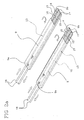
Fig. 2a shows a first detail of the devices seen inFig. 1 ; -
Fig. 2b shows a second detail of the devices seen inFig. 1 ; -
Fig. 3 is a diagrammatic top view of an ink-jet printing apparatus provided with the two devices shown inFig. 1 . - With reference to the drawings, a device for radiation drying comprising at least one
lamp 2, preferably but not exclusively a UV light lamp, has been generally identified byreference numeral 1. - In the example in
Fig. 1 , two of saiddevices 1 are mounted on an ink-jet printing apparatus electronically controlled by a processor. In this apparatus, a plurality ofarticles 3 is laid on a support or tray 4 driven in relative motion with respect to thedrying device 1. - In ink-jet printing apparatus of the traditional type, the
support 4 is fixed, whereas thewhole drying device 1 is slidably movable along a printing and drying direction "F". - Alternatively, as shown in this example, the
support 4 is slidably movable along the printing and drying direction "F" and thedrying device 1 is mounted on a fixed supporting structure (not shown). In more detail, thesupport 4 defines a reciprocating motion along the direction "F" so as to repeatedly bring thearticles 3 below the print heads and thelamps 2, to enable printing, i.e. laying of the ink, and full drying of thearticle 3 in several steps. - The
lamps 2 are disposed with the respective main extension axis at right angles to the direction "F". Saidlamps 2 are enclosed into respective lamp-holding boxes 5 inside which, in addition, a cooling liquid flows to remove the excess heat generated by thelamps 2. To this aim,lamps 2 are fully surrounded by, and/or dipped in this liquid. Preferably, but not exclusively, the cooling liquid consists of water. - The
drying device 1 further comprises a plate-like structure 6 put under eachlamp 2. This plate-like structure has abase 6a of essentially elongated rectangular shape andflaps 6b along the major sides which are folded in a "C" configuration. - The plate-
like structure 6 has the function of closing each lamp-holding box 5 at the lower part thereof. InFig. 1 , the lamp-holding boxes 5 are represented spaced apart from the supportingstructure 6 for the sake of clarity. Actually, a lower end of eachbox 5 lies between the two C-folded sides preventing lateral escape of the UV radiation. Thelamp 2 is therefore very close to thearticles 3 to be dried, so that the emitted radiation can reach thearticles 3 almost completely and the amount of power lost is minimised. - A window 7 is formed on the
base 6a of each supportingstructure 6, at the region along which thesupport 4 with thearticles 3 carried thereon travels, so that the UV light beam is enabled to impinge on thearticles 3 themselves. The shape of the window 7 essentially depends on the shape of thearticles 3. In the embodiment shown, in whicharticles 3 consist of discs, such as CD's and DVD's, the window 7 is substantially of rectangular shape. - Since during the printing and drying process there are work steps during which the articles are not disposed under the
drying devices 1 and therefore said dryingdevices 1 operate to no purpose, it is suitable to prevent said UV light beam from impinging on the print heads during said steps. In fact, an impact of the radiation against the head nozzles for long periods of time and in great amounts surely damages said nozzles. - To this aim, the window 7 is provided with an
opening screen 8. This openingscreen 8 comprises at least one movable wall. In the example under discussion, thescreen 8 comprises twomovable walls 9 of elongated rectangular shape. These walls are shiftable close to or away from each other. - In more detail, the
walls 9 are movable between a first position at which the window 7 is closed and the UV light beam is intercepted, and a second position at which the window 7 is open and the UV light beam can impinge on theunderlying articles 3. - The
movable walls 9 slide along astraight bar 10 and on thebase 6a of the plate-like supportingstructure 6. Movement of said walls is preferably ensured by a respectivelinear actuator 11, of the pneumatic type for example. - The
drying device 1 advantageously comprises aliquid cooling plant 12 integrated into themovable walls 9 of thescreen 8. In fact, at the inside of eachwall 9ducts 13 are formed along which the cooling liquid flows. - In the preferred embodiment herein depicted, the
ducts 13 consist of afirst hole 14 and asecond hole 15; they are both through holes and are parallel to each other. Said holes 14, 15 extend from afirst end 9a of each wall to asecond end 9b, opposite to the first one 9a. In addition, athird hole 16 is made perpendicular to the first 14 and second 15 holes. Thethird hole 16 passes through thefirst hole 14 and opens into thesecond hole 15. Thethird hole 16 is made close to thesecond end 9b of eachwall 9. The outlet of thethird hole 16 and the outlets of the first 14 and second 15 holes in the vicinity of thesecond end 9b of eachwall 9 are closed by means ofplugs 17. In this manner, a U-shaped pipe coil is obtained. The pipe coil could in any case have a different shape, depending each time on the specific requirements. - Connected to the outlets of the first 14 and second 15 holes are
pipes 18 defining the coil delivery side and return side and they are connected to other components of the cooling plant not shown, such as a radiator and a pump for example. - The cooling plant further comprises a
heat exchanger 19 placed under thebase 6a of each plate-like structure 6 and disposed in side by side relationship with the window 7. - The
heat exchanger 19 comprises aplate 20 of substantially rectangular shape. Aface 20a of eachplate 20 is put into contact with thebase 6a of the supportingstructure 6. - Formed within the
plate 20 areducts 21 similar to those formed in eachmovable wall 9. In detail, saidducts 21 have a first 22 and a second 23 holes, consisting both of mutually parallel through holes, and athird hole 24 perpendicular to the first 22 and second 23 holes. - The
third hole 24 passes through thefirst hole 22 and opens into thesecond one 23. The outlets of thethird hole 24 and those of thefirst hole 22 and thesecond hole 23 placed at oneend 20b ofplate 20 are closed byplugs 17. In this manner a U-shaped pipe coil is obtained that is quite similar to that of themovable walls 9. This pipe coil too could in any case have a different shape, depending each time on the specific requirements. -
Further pipes 18 are connected to theplate 20 of theheat exchanger 19 to move away and cool the liquid. - The cooling liquid therefore runs in the
ducts 13 of themovable walls 9 and in theducts 21 of theheat exchanger 19, drawing the heat produced by the UV light beam impacting against the metal surfaces of thedrying device 1. - The cooling liquid typically consists of water. However, also other types of liquids can be used. In fact, should a power increase be required in the UV lamps, there would be too much heat to be removed and water would not be sufficient any longer. In this case, liquids characterised by a boiling temperature higher than 100°C are used.
- Alternatively, the water can be maintained to a higher pressure than the atmospheric one so as to increase its boiling temperature.
- The
drying device 1 is advantageously mounted on an ink-jet printing apparatus 25 to printarticles 3 preferably but not exclusively made of plastic material (Fig. 3 ) such as CD's or DVD's. - In the described embodiment,
apparatus 25 comprises twodrying devices 1 both mounted on abase 26 of theapparatus 25 itself. - This
printing apparatus 25 comprises at least oneprint head printing apparatus 25 involves a four-colour process and therefore on the whole uses five inks of different colours (black, magenta, cyan, yellow and a colour designed to constitute a background such as white). It is therefore possible for an ink to feed more than one head. - In more detail, the
present printing apparatus 25 comprises sixmain print heads 27a for a four-colour printing process and two furtherauxiliary heads 27b for printing of the background. - The
printing apparatus 25 further comprises an ink-containingtank 28 connected to ametering device 30 by means of a regulatingvalve 29. Themetering device 30 is connected to the print head or heads 27a, 27b. - The
printing apparatus 25 further comprises acleaning device 31 for theprint heads device 31 comprises a plurality ofsuction openings 32 associated with eachhead suction openings 32 are mounted on supportingplates 33. Theplates 33 are movable in a substantially vertical direction so that thesuction openings 32 can be reached by theheads - The
articles 3 to be printed lie on asupport 4 movable in a reciprocating motion in the printing direction "F". Thesupport 4 is positioned along a centralstraight guide 34 extending in the longitudinal extension of theprinting apparatus 25 and is fastened to thebase 26. Thesupport 4 is moved by a suitable linear motor (not shown). - The print heads 27a, 27b are housed on a
carriage 35 movable in a direction "G" perpendicular to the printing direction "F" along suitable parallel slides 36. - More specifically, all
heads main heads 27a intended for a four-colour printing process, are out of alignment relative to theauxiliary heads 27b reserved for printing of the background so that, during each passage ofarticles 3 under theheads articles 3 without previous laying of the background. - The
printing apparatus 25 comprises two UVlight drying devices 1. Saiddevices 1 are mounted on thebase 26 of theprinting apparatus 25 and in particular they are mounted under thecarriage 35 housing theheads 27. - In more detail, the plate-
like structure 6 of each of thedevices 2 is integral with thebase 26 and placed on thesupport 4 while the lamp-holdingbox 5 is integral with thecarriage 35 and moves with the latter along the direction "G" perpendicular to the printing direction "F". Thebox 5 therefore slides on the plate-like structure 6 and between the C-foldedflaps 6b. In this way thelamp 2 follows theheads box 5 is centred on the window 7 and irradiates themovable walls 9, most of the produced heat is eliminated by the liquid running inducts 13, whereas when thebox 5 moves towards theheat exchanger 19 and irradiates the overlying plate-like structure 6, elimination of the greatest amount of the produced heat is carried out by the liquid contained inducts 21 of saidheat exchanger 19. - In accordance with an alternative embodiment not shown, the
box 5 is fixed and integral with the plate-like structure 6 mounted on thebase 26. In this embodiment, the central portion oflamp 2 is long enough to cover the whole path of theheads - The
first drying device 1 is mounted between themain heads 27a and theauxiliary heads 27b. The function of this device is mainly to dry the background ink layer disposed onarticles 3. - The second device drying 1 is mounted to a position opposite to the first device with respect to the
main heads 27a and its task is to dry the coloured ink layer laid on the background. -
Articles 3 are loaded and unloaded fromsupport 4 by suitable handling means 38 that preferably comprises amovable frame 39. Themovable frame 39 is made up of twoparallel bars 40 joined together by a plurality ofcrosspieces 41. Disposed along said bars 40 is suitable grip means 42 preferably although not exclusively consisting of suction outlets. - The
printing apparatus 25 further comprises a firstloading conveyor belt 43 connected to afirst loading magazine 44 containing thearticles 3 to be printed, i.e. on which ink is to be laid, and a secondunloading conveyor belt 45 connected to asecond unloading magazine 46 into which the already printedarticles 3 are stored. - Extending between the
loading conveyor belt 43 and the unloadingconveyor belt 45 is saidlinear guide 34 so that thesupport 4 can be brought to an intermediate position between theloading conveyor belt 43 and the unloadingconveyor belt 45. - Said
frame 39 is movable in a horizontal direction between a first position, at which one of thebars 40 is in superposed relationship with theloading belt 43 and a second position at which theother bar 40 is in superposed relationship with the unloadingbelt 45. Theframe 39 is also movable in a vertical direction between a raised position and a lowered position. - In the loading and unloading steps, the
frame 39 takes up the first horizontal position, so that onebar 40 is on thearticles 3 to be printed and disposed on theloading belt 43 and theother bar 40 is on the printedarticles 3 laid on thesupport 4. - The
movable frame 39 moves downwards and the grip means 42 is actuated to grasp thearticles 3 that are raised simultaneously withframe 39. - Subsequently, the
frame 39 is shifted to the second horizontal position at which thebar 40 carrying thearticles 3 to be printed is over thesupport 4, and thebar 40 carrying the printedarticles 3 is over the unloadingconveyor belt 45. - Finally, the
frame 39 moves downwards and deactivation of the grip means 42 occurs. In this way, thearticles 3 to be printed lie on thesupport 4 and the printedarticles 3 lie on the unloadingconveyor belt 45. - Said handling means 38 further comprises a
cross structure 47 ensuring connection between themagazines conveyor belts cross structure 47 is provided with grip means (not shown in the figures) that generally consists of suction outlets. Thecross structure 47 is movable in a vertical direction and is driven in rotation about its substantially vertical axis due to a respective motor, not shown. Thecross structure 47 is provided with fourarms 48 and carries out loading and unloading of the articles onto and from theconveyor belts cross structure 47 by the grip means, grasps a printedarticle 3 from the unloadingconveyor belt 45 and an article to be printed 3 from theloading magazine 44. After a 180° rotation, thecross structure 47 releases the article to be printed 3 onto theloading conveyor belt 43 and the printedarticle 3 into the unloadingmagazine 49. Simultaneously, thecross structure 47 grasps a printedarticle 3 again from the unloadingconveyor belt 45 and an article to be printed 3 from theloading magazine 44. - The
loading magazine 44 and unloadingmagazine 46 each comprise a revolvingplate 49 provided with a plurality of seats adapted to carry thearticles 3. In the specific example, saidarticles 3. consist of optically readable discs such as CD's or DVD's and the necessary seats to carry them are defined byvertical rods 50. - The present invention achieves the intended purposes and has important advantages.
- First of all, the
liquid cooling plant 12 mounted in thedrying device 1 is more efficient in removing the heat generated by an interaction of the UV light beam with the metal walls. Therefore, the UV light lamps can be maintained switched on, the screen walls being closed, also during short servicing interventions, without being obliged to actuate them again and wait for heating of same before restarting working. Therefore, the time and amount of the radiation impinging on the print heads can be reduced, which will result in an increase in the lifetime of the heads and an improvement in the print quality. - In addition, the
liquid cooling plant 12 enables use of fans of big sizes to be avoided for generating the necessary air flow. The coolingplant 12 is therefore more compact and consequently thedrying device 1 andprinting apparatus 25 on which it is mounted are characterised by a reduced bulkiness. Since there is no air flow impinging on the ink emitted from the heads, the print quality is excellent. Furthermore, due to the absence of fans, thedrying device 1 is much more noiseless and the trouble of the operators working in the vicinity of theprinting apparatus 25 is practically eliminated. - Finally, since in the
cooling plant 12 also liquids other than water can be used in order to be able to eliminate bigger heat amounts, thedevice 1 is very versatile, as it is adapted for different operating conditions.
Claims (18)
- An ink-jet printing apparatus comprising a base (26), a support (4) movable in a printing direction (F) and able to carry articles (3) to be printed, a carriage (35) movable in a direction (G) perpendicular to the printing direction (F), at least one print head (27a, 27b) mounted on the carriage (35); a device (1) for radiation drying placed alongside said head (27a, 27b) ; said device (1) for radiation drying, comprising at least one lamp (2) able to emit a radiation beam, and at least one opening screen (8) interposed interposable between said lamp (2) and the printed articles (3) to be dried, to alternately intercept the radiation beam, said opening screen (8) further comprising a liquid cooling plant (12).
- An apparatus as claimed in claim 1, characterised in that said opening screen (8) comprises at least one movable wall (9).
- An apparatus as claimed in claim 2, characterised in that said liquid cooling plant (12) has a duct (13) internal to said movable wall (9) for passage of a cooling liquid.
- An apparatus as claimed in claim 2, characterised in that said opening screen (8) further comprises a plate-like structure (6).
- An apparatus as claimed in claim 4, characterised in that said liquid cooling plant (12) further comprises a heat exchanger (19) put into contact with said plate-like structure (6).
- An apparatus as claimed in claim 5, characterised in that said heat exchanger (19) comprises a plate (20) provided with an internal duct (21) for passage of a cooling liquid.
- An apparatus as claimed in claim 4, characterised in that the apparatus comprises a printed article (3) to be dried and said plate-like structure (6) has a window (7) in register with the printed article (3), so that only the printed article (3) to be dried is exposed to the lamp (2) light.
- An apparatus as claimed in claim 7, characterised in that said movable wall (9) is positioned on said window (7).
- An apparatus as claimed in claim 7, characterised in that said movable wall (9) is slidable on said plate-like structure (6) between a first position at which said movable wall (9) closes said window (7) and intercepts the radiation beam, and a second position at which said movable wall (9) opens said window (7) enabling the radiation beam to pass therethrough and impinge on the article (3) to be dried.
- An apparatus as claimed in anyone of the preceding claims, characterised in that said opening screen (8) comprises two movable walls (9) slidable in the same plane and moving close to or away from each other.
- An apparatus as claimed in anyone of the preceding claims, characterised in that said lamp (2) is provided with a liquid cooling plant.
- An apparatus as claimed in anyone of the preceding claims, characterised in that said lamp (2) is contained in a lamp-holding box (5) with an open side to irradiate the articles (3).
- An apparatus as claimed in the preceding claim when depending on claim 7, characterised in that said box (5) is slidable on the plate-like structure (6) between a position close to the window (7) and a position close to a heat exchanger (19) disposed in side by side relationship with the window (7) and in contact with said plate-like structure (6).
- An apparatus as claimed in anyone of the preceding claims, characterised in that said cooling liquid is water.
- An apparatus as claimed in anyone of the preceding claims, characterised in that said radiation is an ultraviolet radiation.
- An apparatus as claimed in one of the preceding claims, characterised in that it comprises two drying devices (1).
- An apparatus as claimed in claim 16, characterised in that said drying devices (1) are placed on the respective sides of said head (27a).
- An apparatus as claimed in claims 1 to 15 when depending on claim 13, characterised in that the box (5) of said at least one drying device (1) is integral with the carriage (35), and the plate-like structure (6) is integral with the base (26) and superposed on the support (4).
Priority Applications (4)
| Application Number | Priority Date | Filing Date | Title |
|---|---|---|---|
| EP05425907A EP1800876B1 (en) | 2005-12-22 | 2005-12-22 | A device for radiation drying |
| AT05425907T ATE388826T1 (en) | 2005-12-22 | 2005-12-22 | A DEVICE FOR DRYING BY RADIATION |
| DE602005005349T DE602005005349T2 (en) | 2005-12-22 | 2005-12-22 | A device for drying by radiation |
| US11/639,723 US20070151118A1 (en) | 2005-12-22 | 2006-12-15 | Device for radiation drying |
Applications Claiming Priority (1)
| Application Number | Priority Date | Filing Date | Title |
|---|---|---|---|
| EP05425907A EP1800876B1 (en) | 2005-12-22 | 2005-12-22 | A device for radiation drying |
Publications (2)
| Publication Number | Publication Date |
|---|---|
| EP1800876A1 EP1800876A1 (en) | 2007-06-27 |
| EP1800876B1 true EP1800876B1 (en) | 2008-03-12 |
Family
ID=36589128
Family Applications (1)
| Application Number | Title | Priority Date | Filing Date |
|---|---|---|---|
| EP05425907A Expired - Lifetime EP1800876B1 (en) | 2005-12-22 | 2005-12-22 | A device for radiation drying |
Country Status (4)
| Country | Link |
|---|---|
| US (1) | US20070151118A1 (en) |
| EP (1) | EP1800876B1 (en) |
| AT (1) | ATE388826T1 (en) |
| DE (1) | DE602005005349T2 (en) |
Families Citing this family (4)
| Publication number | Priority date | Publication date | Assignee | Title |
|---|---|---|---|---|
| US8011114B2 (en) * | 2009-12-04 | 2011-09-06 | Superior Investments, Inc. | Vehicle dryer with butterfly inlet valve |
| US11890877B2 (en) | 2019-08-30 | 2024-02-06 | Primera Technology, Inc. | Food product platform for food product printer |
| DE102021129275A1 (en) * | 2021-11-10 | 2023-05-11 | Syntegon Technology Gmbh | Device for sealing capsules |
| WO2025175262A1 (en) * | 2024-02-16 | 2025-08-21 | Worcester Polytechnic Institute | Laser driven commercial drying |
Family Cites Families (91)
| Publication number | Priority date | Publication date | Assignee | Title |
|---|---|---|---|---|
| US2735364A (en) * | 1956-02-21 | Moller | ||
| US1666308A (en) * | 1926-03-04 | 1928-04-17 | News Projection Corp | Mechanism for controlling the tension of ticker tape |
| US2074455A (en) * | 1932-02-05 | 1937-03-23 | Nat Electric Heating Company I | Electric heating and drying roll |
| US2268594A (en) * | 1939-08-03 | 1942-01-06 | Huber J M Inc | Process of letterpress printing |
| US2338234A (en) * | 1941-01-02 | 1944-01-04 | Rca Corp | Evaporation of transparent material on glass |
| US2552209A (en) * | 1947-09-17 | 1951-05-08 | Eastman Kodak Co | Fusion photothermography |
| US3078589A (en) * | 1956-12-03 | 1963-02-26 | Xerox Corp | Xerographic fusing apparatus |
| NL295730A (en) * | 1962-07-25 | 1900-01-01 | ||
| CH401689A (en) * | 1962-09-01 | 1965-10-31 | Hell Rudolf Dr Ing Fa | Process for the production of printing forms, in particular gravure printing forms |
| US3302579A (en) * | 1965-08-25 | 1967-02-07 | Monsanto Co | Electrostatic printing with oscillating screen frame and dual printing at a single station |
| US3302580A (en) * | 1965-08-25 | 1967-02-07 | Monsanto Co | Electrostatic printing with rotating screen frame and plural print stations |
| DE1508496A1 (en) * | 1966-04-13 | 1970-03-26 | Metallgesellschaft Ag | Device for preheating solid material |
| US3500734A (en) * | 1967-10-04 | 1970-03-17 | California Computer Products | Photographic recorder and processor |
| US3694245A (en) * | 1967-10-10 | 1972-09-26 | Bror E Anderson | Thermographic stencil sheet,manufacture thereof,and method of making an imaged stencil sheet |
| US3529360A (en) * | 1968-11-04 | 1970-09-22 | Olivetti & Co Spa | Reprographic output feed system |
| US3661578A (en) * | 1969-04-01 | 1972-05-09 | Polaroid Corp | Dryer |
| US3760724A (en) * | 1971-04-23 | 1973-09-25 | Addressograph Multigraph | Fast-set plastisol ink |
| US3745307A (en) * | 1971-05-06 | 1973-07-10 | Sun Chemical Corp | Apparatus for curing solvent-free printing material |
| US3722105A (en) * | 1971-07-06 | 1973-03-27 | Owens Illinois Inc | Apparatus and method for applying radio frequency energy to a moving web of material |
| GB1397077A (en) * | 1971-07-16 | 1975-06-11 | Hanovia Lamps Ltd | Ink drying reflector system |
| US3894343A (en) * | 1972-06-15 | 1975-07-15 | Thermogenics Of New York | Ink curing and drying apparatus |
| US4042401A (en) * | 1972-12-06 | 1977-08-16 | Columbia Ribbon And Carbon Manufacturing Co., Inc. | Hectograph products and process |
| US3826014A (en) * | 1973-03-19 | 1974-07-30 | Sun Chemical Corp | Shutter mechanism for radiation-curing lamp |
| US4010687A (en) * | 1973-04-13 | 1977-03-08 | Xerox Corporation | Planographic printing master |
| US3930318A (en) * | 1973-04-23 | 1976-01-06 | Continental Can Company, Inc. | Ultraviolet curing machine |
| CH576869A5 (en) * | 1973-05-11 | 1976-06-30 | Mohn Reinhard Mohndruck Ohg | |
| US3909256A (en) * | 1973-12-26 | 1975-09-30 | Xerox Corp | Electrostatographic process for preparing screen printing member |
| US3967385A (en) * | 1974-08-26 | 1976-07-06 | National-Standard Company, Wagner-Litho Machinery Division | Utilization of heat pipes for cooling radiation curing systems |
| US4005135A (en) * | 1975-04-07 | 1977-01-25 | Sun Chemical Corporation | Rotatable ultraviolet lamp reflector and heat sink |
| US4152986A (en) * | 1976-12-03 | 1979-05-08 | Dadowski Gilbert F | Method and apparatus for printing raised ink images |
| DE2659486C2 (en) * | 1976-12-30 | 1978-12-07 | Hoechst Ag, 6000 Frankfurt | Developing device for developing sheets of diazo copy material |
| NZ186674A (en) * | 1977-04-18 | 1980-12-19 | Screen Printing Supplies | Drying photo-developing ink infrared filter intercepts some of direct light |
| EP0003414B1 (en) * | 1978-01-27 | 1981-11-04 | Spooner Edmeston Engineering Limited | Float treatment apparatus |
| US4424089A (en) * | 1980-05-08 | 1984-01-03 | Sullivan Donald F | Photoprinting process and apparatus for exposing paste-consistency photopolymers |
| SE8205095D0 (en) * | 1982-09-08 | 1982-09-08 | Infraroedteknik Ab | SETTING TO HEAT PROCESS A CONTINUOUS MATERIAL COAT, IN PARTICULAR DRYING OF A PAPER COAT, AND DEVICE FOR IMPLEMENTATION OF THE SET |
| AU2935384A (en) * | 1983-06-24 | 1985-01-03 | Screen Printing Supplies Pty. Ltd. | Heat curing apparatus |
| US4768437A (en) * | 1986-06-03 | 1988-09-06 | Porelon, Inc. | High contrast printing material |
| FI75008C (en) * | 1986-03-14 | 1992-02-17 | Valmet Oy | Float dryer and method for streamlining its function |
| US4824621A (en) * | 1987-01-27 | 1989-04-25 | Porelon, Inc. | Method for making an ink-impregnated material |
| US4811493A (en) * | 1987-08-05 | 1989-03-14 | Burgio Joseph T Jr | Dryer-cooler apparatus |
| FI78525C (en) * | 1987-11-02 | 1989-08-10 | Valmet Paper Machinery Inc | infra-drying |
| FI79156C (en) * | 1988-03-08 | 1989-11-10 | Valmet Paper Machinery Inc | Procedure in an integrated IR dryer / yankee cover and IR dryer / yankee cover. |
| US5092059A (en) * | 1988-06-07 | 1992-03-03 | W. R. Grace & Co.-Conn. | Infrared air float bar |
| US5199623A (en) * | 1989-01-06 | 1993-04-06 | Valmet Paper Machinery Inc. | Device for supporting, turning and spreading of a web |
| DE3915278A1 (en) * | 1989-05-10 | 1990-11-15 | Hoechst Ag | METHOD AND DEVICE FOR THE CONTINUOUS DRYING OF PLATES COATED ON BOTH SIDES |
| US5160399A (en) * | 1989-09-25 | 1992-11-03 | Canon Kabushiki Kaisha | Laminating apparatus |
| US5048198A (en) * | 1989-11-20 | 1991-09-17 | Burgio Joseph T Jr | Shutter system for shielding a coated substrate during a radiation-curing process |
| US5019868A (en) * | 1989-12-28 | 1991-05-28 | Am International, Inc. | Developer electrode and reverse roller assembly for high speed electrophotographic printing device |
| US5043749A (en) * | 1989-12-29 | 1991-08-27 | Am International Inc. | Printing press and method |
| US5094010A (en) * | 1990-07-05 | 1992-03-10 | Amjo Infra-Red And Ultra-Violet Drying Systems, Inc. | Vented ultraviolet drying system for drying fiberglass resins in boat hulls and decks |
| DE69120645T2 (en) * | 1990-12-26 | 1997-02-13 | Ricoh Kk | Reversible thermosensitive recording composition, recording medium, recording method and display device using the recording medium |
| NL9201065A (en) * | 1992-06-16 | 1994-01-17 | Od & Me Bv | Device for processing disc-shaped record carriers. |
| FR2710971B1 (en) * | 1993-10-06 | 1995-12-29 | Infra Rouge System | Non-contact deflection device for sheet material. |
| US5518542A (en) * | 1993-11-05 | 1996-05-21 | Tokyo Electron Limited | Double-sided substrate cleaning apparatus |
| US5731157A (en) * | 1993-12-30 | 1998-03-24 | The Procter And Gamble Company | Two-site allergen immunoassay |
| GB9400259D0 (en) * | 1994-01-07 | 1994-03-02 | Pilkington Plc | Substrate for a magnetic disc and manufacture thereof |
| US5622652A (en) * | 1995-06-07 | 1997-04-22 | Img Group Limited | Electrically-conductive liquid for directly printing an electrical circuit component onto a substrate, and a method for making such a liquid |
| US5656081A (en) * | 1995-06-07 | 1997-08-12 | Img Group Limited | Press for printing an electrical circuit component directly onto a substrate using an electrically-conductive liquid |
| US5651316A (en) * | 1995-10-02 | 1997-07-29 | Howard W. DeMoore | Retractable printing/coating unit operable on the plate and blanket cylinders simultaneously from the dampener side of the first printing unit or any consecutive printing unit of any rotary offset printing press |
| WO1997014157A1 (en) * | 1995-10-07 | 1997-04-17 | Img Group Limited | An electrical circuit component formed of a conductive liquid printed directly onto a substrate |
| US5634402A (en) * | 1995-10-12 | 1997-06-03 | Research, Incorporated | Coating heater system |
| US5595118A (en) * | 1995-10-16 | 1997-01-21 | F & L Machinery Design, Inc. | Drying apparatus for a dry off-set printing press having an ultra-violet lamp assembly |
| FI98944C (en) * | 1995-10-25 | 1997-09-10 | Valmet Corp | Method and apparatus for drying the coating of a paper web or equivalent |
| US6037085A (en) * | 1996-06-19 | 2000-03-14 | Printing Development Inc. | Photoresists and method for making printing plates |
| US6375742B2 (en) * | 1996-07-25 | 2002-04-23 | Kabushiki Kaisha Toshiba | Apparatus for processing paper sheets to decolor an image formed thereon |
| JP2001508715A (en) * | 1997-01-27 | 2001-07-03 | オーセ プリンティング システムズ ゲゼルシャフト ミット ベシュレンクテル ハフツング | Method and apparatus for forming a printed image on a printed material using a structured ice layer |
| DE29901402U1 (en) * | 1998-01-27 | 1999-05-12 | DeMoore, Howard W., Dallas, Tex. | Intermediate infrared heating |
| US6116595A (en) * | 1998-04-13 | 2000-09-12 | Quad/Graphics, Inc. | Sheet diverter wedge including air discharge ports |
| US6047151A (en) * | 1998-05-06 | 2000-04-04 | Imation Corp. | Drying system and method for an electrophotographic imaging system |
| US6058621A (en) * | 1998-06-05 | 2000-05-09 | Eastman Kodak Company | Apparatus and method for drying photosensitive material using radiant heat and air flow passages |
| US6387588B1 (en) * | 1999-04-09 | 2002-05-14 | Ricoh Company, Ltd. | Plate material for printing method based on wettability change |
| US6314879B1 (en) * | 1999-05-12 | 2001-11-13 | Hurletron Incorporated | Flexographic printing apparatus |
| US6571711B1 (en) * | 1999-10-29 | 2003-06-03 | Air Motion Systems, Inc. | Print cylinder cooling system |
| GB0024533D0 (en) * | 2000-10-06 | 2000-11-22 | Geola Uab | A laser system |
| US6520084B1 (en) * | 2000-11-13 | 2003-02-18 | Creo Inc. | Method for making printing plate using inkjet |
| US20030017310A1 (en) * | 2001-03-16 | 2003-01-23 | Steve Young | Apparatus and method for efficiently producing high quality laminating substrates using liquid laminates and a resulting laminated product thereof |
| JP4268345B2 (en) * | 2001-04-20 | 2009-05-27 | 富士フイルム株式会社 | Support for lithographic printing plate |
| CN1272186C (en) * | 2001-07-06 | 2006-08-30 | 富士胶片株式会社 | Original plate of plane printing plate |
| DE10152593A1 (en) * | 2001-10-24 | 2003-05-08 | Koenig & Bauer Ag | Device for printing material and printing unit cooling by means of cooled blown air on sheet-fed rotary printing machines |
| DE10225198B4 (en) * | 2002-06-06 | 2007-07-12 | Polytype S.A. | Method and apparatus for printing a multicolor image |
| US7027887B2 (en) * | 2002-07-03 | 2006-04-11 | Theries, Llc | Apparatus, systems and methods for use in three-dimensional printing |
| US7465909B2 (en) * | 2003-01-09 | 2008-12-16 | Con-Trol-Cure, Inc. | UV LED control loop and controller for causing emitting UV light at a much greater intensity for UV curing |
| US20040164325A1 (en) * | 2003-01-09 | 2004-08-26 | Con-Trol-Cure, Inc. | UV curing for ink jet printer |
| JP4237556B2 (en) * | 2003-06-26 | 2009-03-11 | 中本パックス株式会社 | Water-based gravure printing method |
| JP4444211B2 (en) * | 2003-07-09 | 2010-03-31 | 旭化成イーマテリアルズ株式会社 | Method for producing relief printing material for seamless printing and production apparatus for relief printing material for seamless printing |
| US7214725B2 (en) * | 2004-04-30 | 2007-05-08 | Ashland Licensing And Intellectual Property Llc | Radiation-curable lithographic inks from multifunctional acrylate oligomers |
| DE102004021600A1 (en) * | 2004-05-03 | 2005-12-08 | Gretag-Macbeth Ag | Device for inline monitoring of print quality in sheetfed offset presses |
| CA2588343C (en) * | 2004-11-24 | 2011-11-08 | Nanotechnologies, Inc. | Electrical, plating and catalytic uses of metal nanomaterial compositions |
| US7469638B2 (en) * | 2004-12-30 | 2008-12-30 | E.I. Du Pont De Nemours And Company | Electronic devices and processes for forming the same |
| US20080087181A1 (en) * | 2006-10-17 | 2008-04-17 | Tal Goichman | Method for producing a flexo plate mold |
| US7966743B2 (en) * | 2007-07-31 | 2011-06-28 | Eastman Kodak Company | Micro-structured drying for inkjet printers |
-
2005
- 2005-12-22 DE DE602005005349T patent/DE602005005349T2/en not_active Expired - Lifetime
- 2005-12-22 EP EP05425907A patent/EP1800876B1/en not_active Expired - Lifetime
- 2005-12-22 AT AT05425907T patent/ATE388826T1/en not_active IP Right Cessation
-
2006
- 2006-12-15 US US11/639,723 patent/US20070151118A1/en not_active Abandoned
Also Published As
| Publication number | Publication date |
|---|---|
| US20070151118A1 (en) | 2007-07-05 |
| ATE388826T1 (en) | 2008-03-15 |
| EP1800876A1 (en) | 2007-06-27 |
| DE602005005349D1 (en) | 2008-04-24 |
| DE602005005349T2 (en) | 2008-06-26 |
Similar Documents
| Publication | Publication Date | Title |
|---|---|---|
| US6647640B2 (en) | Drying station and method for drying printed sheets and printing machine having a drying station | |
| EP2206608B1 (en) | Curing | |
| JP5145246B2 (en) | Equipment for printing objects, especially plastic parts | |
| CN108367576B (en) | Inkjet printing device with removable flat substrate support | |
| EP2546061B1 (en) | Recording apparatus | |
| JPH11504850A (en) | Method and apparatus for curing a layer on a substrate | |
| US20220040986A1 (en) | Liquid Discharge Apparatus, Head Unit and Mist Collector | |
| EP1800876A1 (en) | A device for radiation drying | |
| JP2011037025A (en) | Ultraviolet irradiation device for inkjet recorder | |
| CN103963460A (en) | Inkjet type recording apparatus | |
| US7954938B2 (en) | Apparatus and process for ink-jet printing | |
| JP7086753B2 (en) | Inkjet printing equipment | |
| JP5880076B2 (en) | Recording device | |
| US7921801B2 (en) | Droplet jetting applicator and method for manufacturing coated body | |
| JP7805153B2 (en) | printer | |
| JP2005125753A (en) | Ink jet recorder | |
| JP2021187678A (en) | Heating device, drying device, liquid ejection device, printing device | |
| TW201221366A (en) | Printing method and printer | |
| JP2007090743A (en) | Inkjet recorder | |
| CN111216460B (en) | Media heating device and printing device | |
| JP2019123512A (en) | Label heating device | |
| US12547077B2 (en) | Printing plate exposure method and apparatus with reduced thermal polymerization | |
| CN117341354B (en) | A rapid ink drying device for newspaper printing and its usage method | |
| JPH084143Y2 (en) | Explosion-proof UV irradiation device | |
| KR102099541B1 (en) | Curing apparatus for printer |
Legal Events
| Date | Code | Title | Description |
|---|---|---|---|
| PUAI | Public reference made under article 153(3) epc to a published international application that has entered the european phase |
Free format text: ORIGINAL CODE: 0009012 |
|
| 17P | Request for examination filed |
Effective date: 20060828 |
|
| AK | Designated contracting states |
Kind code of ref document: A1 Designated state(s): AT BE BG CH CY CZ DE DK EE ES FI FR GB GR HU IE IS IT LI LT LU LV MC NL PL PT RO SE SI SK TR |
|
| AX | Request for extension of the european patent |
Extension state: AL BA HR MK YU |
|
| GRAP | Despatch of communication of intention to grant a patent |
Free format text: ORIGINAL CODE: EPIDOSNIGR1 |
|
| GRAS | Grant fee paid |
Free format text: ORIGINAL CODE: EPIDOSNIGR3 |
|
| GRAA | (expected) grant |
Free format text: ORIGINAL CODE: 0009210 |
|
| AKX | Designation fees paid |
Designated state(s): AT BE BG CH CY CZ DE DK EE ES FI FR GB GR HU IE IS IT LI LT LU LV MC NL PL PT RO SE SI SK TR |
|
| AK | Designated contracting states |
Kind code of ref document: B1 Designated state(s): AT BE BG CH CY CZ DE DK EE ES FI FR GB GR HU IE IS IT LI LT LU LV MC NL PL PT RO SE SI SK TR |
|
| REG | Reference to a national code |
Ref country code: GB Ref legal event code: FG4D |
|
| REG | Reference to a national code |
Ref country code: CH Ref legal event code: EP |
|
| REG | Reference to a national code |
Ref country code: IE Ref legal event code: FG4D |
|
| REF | Corresponds to: |
Ref document number: 602005005349 Country of ref document: DE Date of ref document: 20080424 Kind code of ref document: P |
|
| PG25 | Lapsed in a contracting state [announced via postgrant information from national office to epo] |
Ref country code: LT Free format text: LAPSE BECAUSE OF FAILURE TO SUBMIT A TRANSLATION OF THE DESCRIPTION OR TO PAY THE FEE WITHIN THE PRESCRIBED TIME-LIMIT Effective date: 20080312 Ref country code: FI Free format text: LAPSE BECAUSE OF FAILURE TO SUBMIT A TRANSLATION OF THE DESCRIPTION OR TO PAY THE FEE WITHIN THE PRESCRIBED TIME-LIMIT Effective date: 20080312 |
|
| PG25 | Lapsed in a contracting state [announced via postgrant information from national office to epo] |
Ref country code: AT Free format text: LAPSE BECAUSE OF FAILURE TO SUBMIT A TRANSLATION OF THE DESCRIPTION OR TO PAY THE FEE WITHIN THE PRESCRIBED TIME-LIMIT Effective date: 20080312 |
|
| NLV1 | Nl: lapsed or annulled due to failure to fulfill the requirements of art. 29p and 29m of the patents act | ||
| ET | Fr: translation filed | ||
| PG25 | Lapsed in a contracting state [announced via postgrant information from national office to epo] |
Ref country code: SI Free format text: LAPSE BECAUSE OF FAILURE TO SUBMIT A TRANSLATION OF THE DESCRIPTION OR TO PAY THE FEE WITHIN THE PRESCRIBED TIME-LIMIT Effective date: 20080312 Ref country code: LV Free format text: LAPSE BECAUSE OF FAILURE TO SUBMIT A TRANSLATION OF THE DESCRIPTION OR TO PAY THE FEE WITHIN THE PRESCRIBED TIME-LIMIT Effective date: 20080312 Ref country code: BE Free format text: LAPSE BECAUSE OF FAILURE TO SUBMIT A TRANSLATION OF THE DESCRIPTION OR TO PAY THE FEE WITHIN THE PRESCRIBED TIME-LIMIT Effective date: 20080312 Ref country code: PL Free format text: LAPSE BECAUSE OF FAILURE TO SUBMIT A TRANSLATION OF THE DESCRIPTION OR TO PAY THE FEE WITHIN THE PRESCRIBED TIME-LIMIT Effective date: 20080312 |
|
| PG25 | Lapsed in a contracting state [announced via postgrant information from national office to epo] |
Ref country code: SK Free format text: LAPSE BECAUSE OF FAILURE TO SUBMIT A TRANSLATION OF THE DESCRIPTION OR TO PAY THE FEE WITHIN THE PRESCRIBED TIME-LIMIT Effective date: 20080312 Ref country code: SE Free format text: LAPSE BECAUSE OF FAILURE TO SUBMIT A TRANSLATION OF THE DESCRIPTION OR TO PAY THE FEE WITHIN THE PRESCRIBED TIME-LIMIT Effective date: 20080612 Ref country code: CZ Free format text: LAPSE BECAUSE OF FAILURE TO SUBMIT A TRANSLATION OF THE DESCRIPTION OR TO PAY THE FEE WITHIN THE PRESCRIBED TIME-LIMIT Effective date: 20080312 Ref country code: PT Free format text: LAPSE BECAUSE OF FAILURE TO SUBMIT A TRANSLATION OF THE DESCRIPTION OR TO PAY THE FEE WITHIN THE PRESCRIBED TIME-LIMIT Effective date: 20080818 Ref country code: ES Free format text: LAPSE BECAUSE OF FAILURE TO SUBMIT A TRANSLATION OF THE DESCRIPTION OR TO PAY THE FEE WITHIN THE PRESCRIBED TIME-LIMIT Effective date: 20080623 |
|
| PG25 | Lapsed in a contracting state [announced via postgrant information from national office to epo] |
Ref country code: RO Free format text: LAPSE BECAUSE OF FAILURE TO SUBMIT A TRANSLATION OF THE DESCRIPTION OR TO PAY THE FEE WITHIN THE PRESCRIBED TIME-LIMIT Effective date: 20080312 Ref country code: NL Free format text: LAPSE BECAUSE OF FAILURE TO SUBMIT A TRANSLATION OF THE DESCRIPTION OR TO PAY THE FEE WITHIN THE PRESCRIBED TIME-LIMIT Effective date: 20080312 |
|
| PG25 | Lapsed in a contracting state [announced via postgrant information from national office to epo] |
Ref country code: IS Free format text: LAPSE BECAUSE OF FAILURE TO SUBMIT A TRANSLATION OF THE DESCRIPTION OR TO PAY THE FEE WITHIN THE PRESCRIBED TIME-LIMIT Effective date: 20080712 |
|
| PLBE | No opposition filed within time limit |
Free format text: ORIGINAL CODE: 0009261 |
|
| STAA | Information on the status of an ep patent application or granted ep patent |
Free format text: STATUS: NO OPPOSITION FILED WITHIN TIME LIMIT |
|
| PG25 | Lapsed in a contracting state [announced via postgrant information from national office to epo] |
Ref country code: DK Free format text: LAPSE BECAUSE OF FAILURE TO SUBMIT A TRANSLATION OF THE DESCRIPTION OR TO PAY THE FEE WITHIN THE PRESCRIBED TIME-LIMIT Effective date: 20080312 |
|
| 26N | No opposition filed |
Effective date: 20081215 |
|
| PG25 | Lapsed in a contracting state [announced via postgrant information from national office to epo] |
Ref country code: EE Free format text: LAPSE BECAUSE OF FAILURE TO SUBMIT A TRANSLATION OF THE DESCRIPTION OR TO PAY THE FEE WITHIN THE PRESCRIBED TIME-LIMIT Effective date: 20080312 Ref country code: BG Free format text: LAPSE BECAUSE OF FAILURE TO SUBMIT A TRANSLATION OF THE DESCRIPTION OR TO PAY THE FEE WITHIN THE PRESCRIBED TIME-LIMIT Effective date: 20080612 |
|
| PG25 | Lapsed in a contracting state [announced via postgrant information from national office to epo] |
Ref country code: MC Free format text: LAPSE BECAUSE OF NON-PAYMENT OF DUE FEES Effective date: 20081231 |
|
| PG25 | Lapsed in a contracting state [announced via postgrant information from national office to epo] |
Ref country code: CY Free format text: LAPSE BECAUSE OF FAILURE TO SUBMIT A TRANSLATION OF THE DESCRIPTION OR TO PAY THE FEE WITHIN THE PRESCRIBED TIME-LIMIT Effective date: 20080312 |
|
| PG25 | Lapsed in a contracting state [announced via postgrant information from national office to epo] |
Ref country code: IE Free format text: LAPSE BECAUSE OF NON-PAYMENT OF DUE FEES Effective date: 20081222 |
|
| PG25 | Lapsed in a contracting state [announced via postgrant information from national office to epo] |
Ref country code: LU Free format text: LAPSE BECAUSE OF NON-PAYMENT OF DUE FEES Effective date: 20081222 Ref country code: HU Free format text: LAPSE BECAUSE OF FAILURE TO SUBMIT A TRANSLATION OF THE DESCRIPTION OR TO PAY THE FEE WITHIN THE PRESCRIBED TIME-LIMIT Effective date: 20080913 |
|
| REG | Reference to a national code |
Ref country code: CH Ref legal event code: PL |
|
| PG25 | Lapsed in a contracting state [announced via postgrant information from national office to epo] |
Ref country code: TR Free format text: LAPSE BECAUSE OF FAILURE TO SUBMIT A TRANSLATION OF THE DESCRIPTION OR TO PAY THE FEE WITHIN THE PRESCRIBED TIME-LIMIT Effective date: 20080312 |
|
| PG25 | Lapsed in a contracting state [announced via postgrant information from national office to epo] |
Ref country code: LI Free format text: LAPSE BECAUSE OF NON-PAYMENT OF DUE FEES Effective date: 20091231 Ref country code: GR Free format text: LAPSE BECAUSE OF FAILURE TO SUBMIT A TRANSLATION OF THE DESCRIPTION OR TO PAY THE FEE WITHIN THE PRESCRIBED TIME-LIMIT Effective date: 20080613 Ref country code: CH Free format text: LAPSE BECAUSE OF NON-PAYMENT OF DUE FEES Effective date: 20091231 |
|
| REG | Reference to a national code |
Ref country code: FR Ref legal event code: PLFP Year of fee payment: 11 |
|
| REG | Reference to a national code |
Ref country code: FR Ref legal event code: PLFP Year of fee payment: 12 |
|
| REG | Reference to a national code |
Ref country code: FR Ref legal event code: PLFP Year of fee payment: 13 |
|
| PGFP | Annual fee paid to national office [announced via postgrant information from national office to epo] |
Ref country code: GB Payment date: 20221220 Year of fee payment: 18 Ref country code: FR Payment date: 20221222 Year of fee payment: 18 |
|
| PGFP | Annual fee paid to national office [announced via postgrant information from national office to epo] |
Ref country code: IT Payment date: 20221222 Year of fee payment: 18 Ref country code: DE Payment date: 20221227 Year of fee payment: 18 |
|
| REG | Reference to a national code |
Ref country code: DE Ref legal event code: R119 Ref document number: 602005005349 Country of ref document: DE |
|
| GBPC | Gb: european patent ceased through non-payment of renewal fee |
Effective date: 20231222 |
|
| PG25 | Lapsed in a contracting state [announced via postgrant information from national office to epo] |
Ref country code: DE Free format text: LAPSE BECAUSE OF NON-PAYMENT OF DUE FEES Effective date: 20240702 |
|
| PG25 | Lapsed in a contracting state [announced via postgrant information from national office to epo] |
Ref country code: GB Free format text: LAPSE BECAUSE OF NON-PAYMENT OF DUE FEES Effective date: 20231222 |
|
| PG25 | Lapsed in a contracting state [announced via postgrant information from national office to epo] |
Ref country code: FR Free format text: LAPSE BECAUSE OF NON-PAYMENT OF DUE FEES Effective date: 20231231 |
|
| PG25 | Lapsed in a contracting state [announced via postgrant information from national office to epo] |
Ref country code: GB Free format text: LAPSE BECAUSE OF NON-PAYMENT OF DUE FEES Effective date: 20231222 Ref country code: FR Free format text: LAPSE BECAUSE OF NON-PAYMENT OF DUE FEES Effective date: 20231231 Ref country code: DE Free format text: LAPSE BECAUSE OF NON-PAYMENT OF DUE FEES Effective date: 20240702 |
|
| PG25 | Lapsed in a contracting state [announced via postgrant information from national office to epo] |
Ref country code: IT Free format text: LAPSE BECAUSE OF NON-PAYMENT OF DUE FEES Effective date: 20231222 |