EP1800869B1 - Ink-feeding device for ink-jet printing apparatus - Google Patents
Ink-feeding device for ink-jet printing apparatus Download PDFInfo
- Publication number
- EP1800869B1 EP1800869B1 EP05425908A EP05425908A EP1800869B1 EP 1800869 B1 EP1800869 B1 EP 1800869B1 EP 05425908 A EP05425908 A EP 05425908A EP 05425908 A EP05425908 A EP 05425908A EP 1800869 B1 EP1800869 B1 EP 1800869B1
- Authority
- EP
- European Patent Office
- Prior art keywords
- ink
- inner space
- print head
- membranes
- case
- Prior art date
- Legal status (The legal status is an assumption and is not a legal conclusion. Google has not performed a legal analysis and makes no representation as to the accuracy of the status listed.)
- Expired - Lifetime
Links
Images


Classifications
-
- B—PERFORMING OPERATIONS; TRANSPORTING
- B41—PRINTING; LINING MACHINES; TYPEWRITERS; STAMPS
- B41J—TYPEWRITERS; SELECTIVE PRINTING MECHANISMS, i.e. MECHANISMS PRINTING OTHERWISE THAN FROM A FORME; CORRECTION OF TYPOGRAPHICAL ERRORS
- B41J2/00—Typewriters or selective printing mechanisms characterised by the printing or marking process for which they are designed
- B41J2/005—Typewriters or selective printing mechanisms characterised by the printing or marking process for which they are designed characterised by bringing liquid or particles selectively into contact with a printing material
- B41J2/01—Ink jet
- B41J2/17—Ink jet characterised by ink handling
- B41J2/175—Ink supply systems ; Circuit parts therefor
Definitions
- the present invention relates to an ink-feeding device for ink-jet printing apparatus.
- the present invention applies to ink-jet printing apparatus for industrial use such as, by way of example, printing of flat plastic supports like optically readable discs (CD's, DVD's), cards or plastic panels in general.
- ink-jet printing apparatus for industrial use such as, by way of example, printing of flat plastic supports like optically readable discs (CD's, DVD's), cards or plastic panels in general.
- ink-jet printing apparatus which are adapted for printing on a surface of plastic material articles. These printing apparatus are provided with electronically controlled print heads, which have the function of drawing the ink from a tank and lay it on a support at a suitable speed, in an amount and following modalities depending on the print to be carried out.
- the print heads are at least one for each colour used, but it is possible to equip the printing apparatus with two or more heads for each colour.
- the heads are mounted on a carriage slidable in a printing direction so that they can reach the points of the article to be printed which in this configuration is maintained stationary.
- the ink for feeding the print heads comes from a tank put upstream of the printing apparatus.
- the feeding device only consists of a duct connecting a lower portion of each ink tank to the corresponding heads.
- the heads distribute ink onto the article, they recall ink from the tank.
- the ink pressure at said lower portion, in the duct and the head is greatly affected by the ink level in the tank itself.
- the hydrostatic pressure exerted on said ink that is reaching the head is drastically reduced.
- inkjet printer with an inkjet head, for recording to a recording medium by jetting the ink, a replaceable ink cartridge which stores the ink, an ink passage reaching the inkjet head from the ink cartridge, an intermediate ink storing bag, formed by a flexible member set in the ink passage, and an ink pressuring supply means for pressuring and supplying from the ink cartridge to an ink storing part side.
- the Applicant has found that the ink-feeding devices for ink-jet printing apparatus of the above described type can be improved under different points of view, particularly as regards the print quality.
- an aim of the present invention to propose an ink-feeding device for ink-jet printing apparatus enabling the print quality to be optimised and maintained uniform during the whole printing step.
- a device ensuring the print quality also when the ink in the tank is about to run dry is an aim of the present invention.
- An ink-feeding device for ink-jet printing apparatus in accordance with the present invention has been generally identified by reference numeral 1.
- the device 1 comprises a tank 2 containing the ink for printing.
- Tank 2 is connected to a metering device 3 by a connecting duct 4.
- An on/off valve 5 is disposed between the tank 2 and the metering device 3 along said duct 4, to enable or prevent passage of the ink flow along the duct 4.
- At least one pipe 6 starts from the metering device 3 and is connected to at least one print head 7.
- two pipes 6 start from the metering device 3 and are connected to two print heads 7 fed with ink of the same colour.
- the articles 8 are laid on a support or tray 9 driven in relative movement with respect to the heads 7.
- the heads 7 are mounted on a movable carriage (not shown) and are electronically controlled by a processor.
- the support 9 carrying the articles 8 is fixed and the carriage carrying the heads 7 is movable in a predetermined printing direction so that the whole surface of articles 8 can be reached.
- the support 9 is slidably movable in the printing direction "F” and the carriage is movable in a direction "G" perpendicular to the printing direction "F".
- the support 9 defines a reciprocating motion along the direction "F” so as to repeatedly take the articles 8 under the print heads 7 to enable full printing of said articles 8 in several steps.
- each head 7 lays an ink band on articles 8, which is of smaller width than that of said articles. Therefore, each article 8 is to be brought again under the heads 7 and said heads 7 are to be shifted in the direction "G" to enable them to be over a region devoid of ink.
- the metering device 3 is therefore interposed between the tank 2 and heads 7.
- the metering device 3 is provided with an inner space 10 having a mainly planar extension. In other words, the flat sizes of the metering device are much more extended than its vertical size.
- the inner space 10 is of a varying volume.
- said space 10 is defined by walls 11 that are movable between a first configuration at which said walls 11 are to their maximum mutual distance ( Fig. 3a , chain line) and a second position at which the walls 11 are to a minimum distance from each other ( Fig. 3b , chain line). In the first position the volume of space 10 is maximum, while in the second position it is minimum.
- the ratio between the diameter "D" of the space 10 and the thickness "S 1 " existing between the walls 11 in the first position is included between 4 and 6.
- the inner space 10 is marked by a substantially symmetric shape with respect to a horizontal symmetry plane "P".
- the metering device 3 comprises an upper horizontal wall 11a and a lower horizontal wall 1b, these walls 11a, 11b facing each other.
- the movable walls 11 generally consist of two thin and flexible membranes 12 separated from each other by a central frame 13. This frame, in addition to supporting and separating the membranes 12, also defines the inner side surface 10a ( Fig. 2 ) of the space 10.
- the frame 13 externally has a square shape and is internally provided with a circular hole 14.
- the inner side wall of hole 14 constituting the side wall 10a of space 10 is rounded and has a convexity facing the inside of the hole 14 itself.
- an inlet duct 15 Formed in a first side 13a of the central frame 13 is an inlet duct 15 consisting of a threaded hole enabling connection of the metering device 3 with the connecting duct 4 coming from tank 2. Through this inlet duct 15, the ink can flow into the space 10.
- a tailpiece 16 of parallelepiped shape is formed on a second side 13b, that is preferably but not exclusively opposite to the first one, of frame 13.
- Two outlet ducts 17 are formed through the tailpiece 16 and frame 13 and they consist of two first through holes 18 parallel to the extension plane of the frame 13 and two second holes 19 the axes of which are perpendicular to the axes of the first holes 18.
- the second holes 19 are such conceived that they open into the first holes 18.
- Respective plugs are applied to the outer end 18a of the first holes 18 so that the ink outflows from the metering device 3 exclusively through the second holes 19 to which the pipes 6 taking the ink into the print heads 7 are connected.
- the metering device 3 further comprises a box-shaped coating case 20 having an inner chamber 21 ( Figs. 3a and 3b ) inside which the components of the metering device 3 are contained.
- Case 20 consists of the central frame 13 and two closing plates 22. Said plates are superposed on the membranes 12 and the central frame 13. All said components of the metering device 3 are pack-wise tightened by a plurality of screws.
- each inner face 22a of the closing plates 22 is a respective recessed portion 23 the shape of which is adapted to house the membranes 12 when the latter are in the first position of maximum mutual distance ( Fig. 3 , chain line).
- the respective recessed portions 23 and the inner side wall 13b of frame 13 define said chamber 21.
- the membranes 12 that are also fastened to the case 20 by their edges 12a, are housed in this chamber 21.
- At least one of the closing plates 22 has a pair of facing holes 24 in mutual alignment and each having its axis parallel to the symmetry plane "P".
- a sensor 25 is disposed inside said holes 24 to determine deformation of the membranes 12.
- this sensor 25 consists of a photoelectric cell capable of sensing the presence or not of a portion of deformed membrane 12 breaking the optical path of the photoelectric cell itself.
- the optical path has its initial point at a transmitter 25a of sensor 25 and terminates at a receiver 25b of sensor 25.
- Sensor 25 is operatively connected to valve 5.
- valve 5 opens and enables a predetermined amount of ink to come out of tank 2.
- This ink fills the inner space 10 of the metering device 3 and causes an elastic deformation of the membranes 12. In this way, there is an increase in the volume of space 10.
- the deformed membranes break the optical path of sensor 25 which drives closure of valve 5.
- Each print head 7 sucks ink from the metering device 3 and lays it on articles 8. In this way, the metering device 3 is slowly emptied and the membranes 12 tend to go back to their non-deformed position ( Fig. 3 , solid line) until the optical path of sensor 25 is restored.
- Sensor 25 therefore controls opening of valve 5 enabling new filling of the inner space 10 in the metering device 3.
- the ratio between said thickness "S 1 " and the thickness "S” between the non-deformed walls 11 is in the range of 1.5 to 2.
- "S" is substantially equal to 10 mm.
- the thickness variation of few millimetres enables the ink feeding pressure to the print heads 7 to be maintained substantially constant.
- said print heads 7 require cleaning, in particular after many printing cycles. In fact, it may happen that solid residues are formed due to ink drying and contamination of the heads 7 with dust. Thus these residues are to be removed as they inhibit an even ink delivery.
- the carriage supporting the heads 7 can take a service position away from articles 8, which position is reached by a displacement along the direction "G".
- cleaning means 26 which substantially consists of suction openings 27 mounted on a supporting plate 28 slidably movable between a lowered rest position and a raised work position.
- further openings not shown can be provided to deliver compressed air to the head nozzles, to help separation of the dry ink and promote suction of same by the suction openings 27.
- the compressed air, associated or not with the sucked air, enables a more efficient removal of the solid residues accumulated on the heads 7.
- the cleaning means 26 contemplates one suction opening 27 associated with each print head 7.
- each suction opening 27 comes into contact with the heads 7 without touching the nozzles of same.
- each suction opening 27 has an edge 27a resting against the respective head 7 around the nozzles preferably sealingly, so that suction of all the residues is ensured ( Fig. 1 ).
- the cleaning action on the heads 7 can be advantageously improved due to high-pressure ejection of a given amount of ink.
- a threaded hole 29 is formed to which respective ducts 30 are applied that are able to carry pressurised air.
- the delivered air causes a pressure increase in the portion of chamber 21 not taken up by the inner space 10.
- the generated pressure acts on the membranes 12 that in this way are moved close to each other.
- the movable walls 11 take the second position of minimum mutual distance and the volume of space 10 is drastically and quickly reduced so that the ink is urged out at a relatively high pressure and speed ( Fig. 3b , chain line).
- the ink under pressure reaches the heads 7 and cooperates to removal of the solid residues impairing the print quality.
- the pressurised ink coming out of the heads together with the residues is collected by the cleaning means 26 and disposed of.
- the device 1 is advantageously mounted on an ink-jet printing apparatus 31 to carry out printing of articles 8 preferably but not exclusively made of plastic material ( Fig. 4 ).
- This printing apparatus 31 comprises, as already mentioned, at least one print head 7 for each colour used.
- the printing apparatus 31 involves a four-colour process and on the whole uses five inks of different colours (black, magenta, cyan, yellow and a colour designed to constitute the background, such as white). It is however possible for an ink to feed more than one head.
- the present printing apparatus 31 comprises six main print heads 7a for a four-colour printing process and two further auxiliary heads 7b for printing of the white base.
- the articles 8a intended for printing lie on a support or tray 9 movable in a reciprocating motion along the printing direction "F".
- the support 9 is positioned along a central straight guide 32 extending in the longitudinal extension of the printing apparatus 31.
- the support 9 is moved by a suitable linear motor (not shown).
- the straight guide 32 is supported by a base "B" of the printing apparatus 1 itself.
- All the print heads 7 are housed on a carriage 33 movable in the direction "G" perpendicular to the print direction "F” along suitable parallel slides 34.
- all heads 7 are aligned in parallel to the printing direction "F".
- the auxiliary heads 7b are out of alignment relative to the main heads 7a so that, during each passage of articles 8 under the heads 7, the background ink band advances that of the coloured ink.
- the coloured ink band does not fully cover the background ink band, so that repeated passages of the articles 8 under the heads 7 are required.
- the printing apparatus 31 further comprises at least one device 35 for radiation drying mounted on a supporting structure (not shown).
- the drying device 35 is necessary for quick drying of the laid ink.
- the printing apparatus 31 comprises two drying devices 35.
- One of the drying devices 35 is placed between the auxiliary heads 7b and the main heads 7a and mainly performs the function of drying the white background ink band.
- the other drying device 35 is on the contrary disposed past the main heads 7a. It is mainly entrusted with the task of drying the coloured ink band.
- suitable handling means 36 that preferably comprises a movable frame 37.
- the movable frame 37 consists of two parallel bars 38 connected by a plurality of crosspieces 39. Disposed along said bars 40 is suitable grip means 42 preferably although not exclusively consisting of suction outlets.
- the printing apparatus 31 further comprises a first loading conveyor belt 41 connected to a first loading magazine 42 containing the articles 8a to be printed, i.e. on which ink is to be laid, and a second unloading conveyor belt 43 connected to a second unloading magazine 44 in which the already printed articles 8b are stored.
- Extending between the loading conveyor belt 41 and the unloading conveyor belt 43 is said linear guide 32 so that the support 9 can be brought to an intermediate position between the loading conveyor belt 41 and the unloading conveyor belt 43.
- Said frame 37 is movable in a horizontal direction between a first position, at which one of the bars 38 is in superposed relationship with the loading belt 41 and a second position at which the other bar 38 is in superposed relationship with the unloading belt 43.
- the frame 37 is also movable in a vertical direction between a raised position and a lowered position.
- the frame 37 takes up the first horizontal position, so that one bar 38 is on the articles 8a to be printed disposed on the loading belt 41, and the other bar 38 is on the printed articles 8b laid on the support 9.
- the movable frame 37 moves downwards and the grip means 40 is actuated to grasp the articles 8 that are raised simultaneously with the frame 37.
- the frame 37 is shifted to the second horizontal position at which the bar 38 carrying the articles 8a to be printed is over the support 9, and the bar 38 carrying the printed articles 8b is over the unloading conveyor belt 43.
- Said handling means 36 further comprises a cross structure 45 ensuring connection between the magazines 42, 44 and the conveyor belts 41, 43.
- the cross structure 45 is provided with grip means (not shown in the figures) that generally consists of suction outlets.
- the cross structure 45 is movable in a vertical direction and is driven in rotation about its substantially vertical axis due to a respective motor, not shown.
- the cross structure 45 is provided with four arms 46 and carries out loading and unloading of the articles onto and from the conveyor belts 41, 43. First of all, the cross structure 45 grasps a printed article 8b from the unloading conveyor belt 43, by means of the grip means, as well as an article to be printed 8a from the loading magazine 42.
- the cross structure 45 releases the article to be printed 8a onto the loading conveyor belt 41 and the printed article 8b into the unloading magazine 44. Simultaneously, the cross structure 45 grasps a printed article 8b again from the unloading conveyor belt 43 and an article to be printed 8a from the loading magazine 42.
- the loading magazine 42 and unloading magazine 44 each comprise a revolving plate 47 provided with a plurality of seats adapted to support the articles 8.
- said articles 8 consist of optically readable discs such as CD's or DVD's and the necessary seats to carry them are defined by vertical rods 48.
- the present invention achieves the intended purposes and has important advantages.
- an ink-feeding device for ink-jet printing apparatus as the described one ensures a print quality that is constant in time also on decreasing of the level of the ink contained in the tank 2.
- the pressure at which the ink enters the heads 7 can be maintained substantially constant, as this pressure is independent of the height of the ink column in tank 2.
- the ink height is reduced and also reduced is the ink variation in height due to consumption.
- the hydrostatic pressure variation exerted by the ink column in the space 10 is negligible and, also due to the presence of valve 5, the level of the ink content in tank 2 is irrelevant.
- a further advantage is concerned with cleaning of the heads 7 carried out by the suction openings 27.
- introduction of compressed air into the metering device 3 and the consequent exit of ink under pressure greatly facilitates removal of the solid residues that are formed for instance due to ink drying or to the presence of dust.
Landscapes
- Ink Jet (AREA)
Abstract
Description
- The present invention relates to an ink-feeding device for ink-jet printing apparatus.
- In particular, the present invention applies to ink-jet printing apparatus for industrial use such as, by way of example, printing of flat plastic supports like optically readable discs (CD's, DVD's), cards or plastic panels in general.
- It is known that ink-jet printing apparatus are available which are adapted for printing on a surface of plastic material articles. These printing apparatus are provided with electronically controlled print heads, which have the function of drawing the ink from a tank and lay it on a support at a suitable speed, in an amount and following modalities depending on the print to be carried out.
- The print heads are at least one for each colour used, but it is possible to equip the printing apparatus with two or more heads for each colour.
- The heads are mounted on a carriage slidable in a printing direction so that they can reach the points of the article to be printed which in this configuration is maintained stationary.
- The ink for feeding the print heads comes from a tank put upstream of the printing apparatus. Generally, the feeding device only consists of a duct connecting a lower portion of each ink tank to the corresponding heads. At the same time as the heads distribute ink onto the article, they recall ink from the tank.
- Disadvantageously, as the ink amount in the tank decreases, a worsening in the print quality occurs. In fact, since the tank has a vertical extension of several ten centimetres, the ink pressure at said lower portion, in the duct and the head, is greatly affected by the ink level in the tank itself. In particular, when the ink level in the tank is reduced to few centimetres, the hydrostatic pressure exerted on said ink that is reaching the head is drastically reduced.
- This phenomenon gives rise to a bad-quality and uneven print. In fact, the reduced pressure causes undesirable variations in the speed and pressure at which ink is sprayed on the article to be printed. The print will appear irregular and with some regions of the support less coated and therefore lighter.
- It is also known from document
JP2004203055 - The Applicant has found that the ink-feeding devices for ink-jet printing apparatus of the above described type can be improved under different points of view, particularly as regards the print quality.
- Accordingly, it is an aim of the present invention to propose an ink-feeding device for ink-jet printing apparatus enabling the print quality to be optimised and maintained uniform during the whole printing step. In detail, it is an aim of the present invention to propose a device substantially maintaining the ink pressure constant in the print heads upon variation of the ink level contained in the tank. In particular, it is an aim of the present invention to propose a device ensuring the print quality also when the ink in the tank is about to run dry.
- Further features and advantages will become more apparent from the detailed description of a preferred but not exclusive embodiment of an ink-feeding device for ink-jet feeding apparatus in accordance with the present invention.
- This description will be set out hereinafter with reference to the accompanying drawings, given by way of non-limiting example, in which:
-
Fig. 1 is a diagrammatic perspective view of an ink-feeding device for ink-jet printing apparatus; -
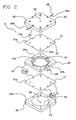
Fig. 2 is an exploded perspective view of a detail of the device seen inFig. 1 ; -
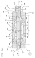
Figs. 3a and3b are section views of the detail seen inFig. 2 in two distinct operating positions; and -
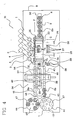
Fig. 4 is a diagrammatic view of an ink-jet printing apparatus comprising the device inFig. 1 . - An ink-feeding device for ink-jet printing apparatus in accordance with the present invention has been generally identified by
reference numeral 1. - The
device 1 comprises a tank 2 containing the ink for printing. Tank 2 is connected to ametering device 3 by a connectingduct 4. An on/offvalve 5 is disposed between the tank 2 and themetering device 3 along saidduct 4, to enable or prevent passage of the ink flow along theduct 4. - At least one
pipe 6 starts from themetering device 3 and is connected to at least one print head 7. In the example herein shown, twopipes 6 start from themetering device 3 and are connected to two print heads 7 fed with ink of the same colour. - The
articles 8 are laid on a support or tray 9 driven in relative movement with respect to the heads 7. - The heads 7 are mounted on a movable carriage (not shown) and are electronically controlled by a processor. In printing apparatus of the traditional type, the
support 9 carrying thearticles 8 is fixed and the carriage carrying the heads 7 is movable in a predetermined printing direction so that the whole surface ofarticles 8 can be reached. - However, in the example shown, the
support 9 is slidably movable in the printing direction "F" and the carriage is movable in a direction "G" perpendicular to the printing direction "F". In more detail, thesupport 9 defines a reciprocating motion along the direction "F" so as to repeatedly take thearticles 8 under the print heads 7 to enable full printing of saidarticles 8 in several steps. - In fact, each head 7 lays an ink band on
articles 8, which is of smaller width than that of said articles. Therefore, eacharticle 8 is to be brought again under the heads 7 and said heads 7 are to be shifted in the direction "G" to enable them to be over a region devoid of ink. - The
metering device 3 is therefore interposed between the tank 2 and heads 7. - The
metering device 3 is provided with aninner space 10 having a mainly planar extension. In other words, the flat sizes of the metering device are much more extended than its vertical size. - This solution enables laying of the ink with a reduced thickness. In this way, the hydrostatic-pressure variation exerted by the ink contained in the
space 10 becomes negligible. - In more detail, the
inner space 10 is of a varying volume. In fact, saidspace 10 is defined bywalls 11 that are movable between a first configuration at which saidwalls 11 are to their maximum mutual distance (Fig. 3a , chain line) and a second position at which thewalls 11 are to a minimum distance from each other (Fig. 3b , chain line). In the first position the volume ofspace 10 is maximum, while in the second position it is minimum. - In terms of sizes, the ratio between the diameter "D" of the
space 10 and the thickness "S1" existing between thewalls 11 in the first position is included between 4 and 6. - In the example shown, "D" is substantially equal to 85 mm, while "S1" substantially corresponds to 16 mm.
- The
inner space 10 is marked by a substantially symmetric shape with respect to a horizontal symmetry plane "P". - In the embodiment herein described, the
metering device 3 comprises an upperhorizontal wall 11a and a lower horizontal wall 1b, thesewalls - The
movable walls 11 generally consist of two thin andflexible membranes 12 separated from each other by acentral frame 13. This frame, in addition to supporting and separating themembranes 12, also defines theinner side surface 10a (Fig. 2 ) of thespace 10. - In this example, the
frame 13 externally has a square shape and is internally provided with acircular hole 14. The inner side wall ofhole 14 constituting theside wall 10a ofspace 10 is rounded and has a convexity facing the inside of thehole 14 itself. - Formed in a
first side 13a of thecentral frame 13 is aninlet duct 15 consisting of a threaded hole enabling connection of themetering device 3 with the connectingduct 4 coming from tank 2. Through thisinlet duct 15, the ink can flow into thespace 10. - A
tailpiece 16 of parallelepiped shape is formed on asecond side 13b, that is preferably but not exclusively opposite to the first one, offrame 13. - Two
outlet ducts 17 are formed through thetailpiece 16 andframe 13 and they consist of two first throughholes 18 parallel to the extension plane of theframe 13 and twosecond holes 19 the axes of which are perpendicular to the axes of thefirst holes 18. Thesecond holes 19 are such conceived that they open into thefirst holes 18. - Respective plugs (not shown in the figures) are applied to the
outer end 18a of thefirst holes 18 so that the ink outflows from themetering device 3 exclusively through thesecond holes 19 to which thepipes 6 taking the ink into the print heads 7 are connected. - The
metering device 3 further comprises a box-shaped coating case 20 having an inner chamber 21 (Figs. 3a and3b ) inside which the components of themetering device 3 are contained. -
Case 20 consists of thecentral frame 13 and two closingplates 22. Said plates are superposed on themembranes 12 and thecentral frame 13. All said components of themetering device 3 are pack-wise tightened by a plurality of screws. - Formed on each
inner face 22a of theclosing plates 22 is a respective recessedportion 23 the shape of which is adapted to house themembranes 12 when the latter are in the first position of maximum mutual distance (Fig. 3 , chain line). - In more detail, the respective recessed
portions 23 and theinner side wall 13b offrame 13 define saidchamber 21. Themembranes 12 that are also fastened to thecase 20 by theiredges 12a, are housed in thischamber 21. - At least one of the
closing plates 22 has a pair of facingholes 24 in mutual alignment and each having its axis parallel to the symmetry plane "P". Asensor 25 is disposed inside saidholes 24 to determine deformation of themembranes 12. - Herein, this
sensor 25 consists of a photoelectric cell capable of sensing the presence or not of a portion ofdeformed membrane 12 breaking the optical path of the photoelectric cell itself. In detail, the optical path has its initial point at atransmitter 25a ofsensor 25 and terminates at areceiver 25b ofsensor 25.Sensor 25 is operatively connected tovalve 5. - During the printing step, the
valve 5 opens and enables a predetermined amount of ink to come out of tank 2. This ink fills theinner space 10 of themetering device 3 and causes an elastic deformation of themembranes 12. In this way, there is an increase in the volume ofspace 10. The deformed membranes break the optical path ofsensor 25 which drives closure ofvalve 5. - Each print head 7 sucks ink from the
metering device 3 and lays it onarticles 8. In this way, themetering device 3 is slowly emptied and themembranes 12 tend to go back to their non-deformed position (Fig. 3 , solid line) until the optical path ofsensor 25 is restored. -
Sensor 25 therefore controls opening ofvalve 5 enabling new filling of theinner space 10 in themetering device 3. - From the point of view of size, the ratio between said thickness "S1" and the thickness "S" between the
non-deformed walls 11 is in the range of 1.5 to 2. In the embodiment herein shown, "S" is substantially equal to 10 mm. - The thickness variation of few millimetres enables the ink feeding pressure to the print heads 7 to be maintained substantially constant.
- Sometimes, said print heads 7 require cleaning, in particular after many printing cycles. In fact, it may happen that solid residues are formed due to ink drying and contamination of the heads 7 with dust. Thus these residues are to be removed as they inhibit an even ink delivery.
- To this aim, the carriage supporting the heads 7 can take a service position away from
articles 8, which position is reached by a displacement along the direction "G". - At this position the heads 7 are put close to cleaning means 26 which substantially consists of
suction openings 27 mounted on a supportingplate 28 slidably movable between a lowered rest position and a raised work position. - Advantageously, further openings not shown can be provided to deliver compressed air to the head nozzles, to help separation of the dry ink and promote suction of same by the
suction openings 27. The compressed air, associated or not with the sucked air, enables a more efficient removal of the solid residues accumulated on the heads 7. - Typically, the cleaning means 26 contemplates one
suction opening 27 associated with each print head 7. - During the cleaning step, the carriage is shifted to the service position and the supporting
plate 28 is shifted to the work position. In this way, thesuction openings 27 comes into contact with the heads 7 without touching the nozzles of same. In particular, eachsuction opening 27 has anedge 27a resting against the respective head 7 around the nozzles preferably sealingly, so that suction of all the residues is ensured (Fig. 1 ). - The cleaning action on the heads 7 can be advantageously improved due to high-pressure ejection of a given amount of ink.
- To this aim, on each of the
closing plates 22 ofcase 20 of themetering device 3, close to the respective centres, a threadedhole 29 is formed to whichrespective ducts 30 are applied that are able to carry pressurised air. In fact, during the cleaning step, the delivered air causes a pressure increase in the portion ofchamber 21 not taken up by theinner space 10. The generated pressure acts on themembranes 12 that in this way are moved close to each other. As a result, themovable walls 11 take the second position of minimum mutual distance and the volume ofspace 10 is drastically and quickly reduced so that the ink is urged out at a relatively high pressure and speed (Fig. 3b , chain line). - The ink under pressure reaches the heads 7 and cooperates to removal of the solid residues impairing the print quality. The pressurised ink coming out of the heads together with the residues is collected by the cleaning means 26 and disposed of.
- The
device 1 is advantageously mounted on an ink-jet printing apparatus 31 to carry out printing ofarticles 8 preferably but not exclusively made of plastic material (Fig. 4 ). - This
printing apparatus 31 comprises, as already mentioned, at least one print head 7 for each colour used. In the example herein shown, theprinting apparatus 31 involves a four-colour process and on the whole uses five inks of different colours (black, magenta, cyan, yellow and a colour designed to constitute the background, such as white). It is however possible for an ink to feed more than one head. - In more detail, the
present printing apparatus 31 comprises sixmain print heads 7a for a four-colour printing process and two furtherauxiliary heads 7b for printing of the white base. - The
articles 8a intended for printing lie on a support ortray 9 movable in a reciprocating motion along the printing direction "F". Thesupport 9 is positioned along a centralstraight guide 32 extending in the longitudinal extension of theprinting apparatus 31. Thesupport 9 is moved by a suitable linear motor (not shown). Thestraight guide 32 is supported by a base "B" of theprinting apparatus 1 itself. - All the print heads 7 are housed on a
carriage 33 movable in the direction "G" perpendicular to the print direction "F" along suitable parallel slides 34. - In more detail, all heads 7 are aligned in parallel to the printing direction "F". The auxiliary heads 7b are out of alignment relative to the
main heads 7a so that, during each passage ofarticles 8 under the heads 7, the background ink band advances that of the coloured ink. In other words, the coloured ink band does not fully cover the background ink band, so that repeated passages of thearticles 8 under the heads 7 are required. - The
printing apparatus 31 further comprises at least onedevice 35 for radiation drying mounted on a supporting structure (not shown). The dryingdevice 35 is necessary for quick drying of the laid ink. In the proposed embodiment, theprinting apparatus 31 comprises twodrying devices 35. - One of the
drying devices 35 is placed between theauxiliary heads 7b and themain heads 7a and mainly performs the function of drying the white background ink band. - The
other drying device 35 is on the contrary disposed past themain heads 7a. It is mainly entrusted with the task of drying the coloured ink band. - The
articles 8 are loaded and unloaded from thesupport 9 by suitable handling means 36 that preferably comprises amovable frame 37. Themovable frame 37 consists of twoparallel bars 38 connected by a plurality ofcrosspieces 39. Disposed along said bars 40 is suitable grip means 42 preferably although not exclusively consisting of suction outlets. - The
printing apparatus 31 further comprises a firstloading conveyor belt 41 connected to afirst loading magazine 42 containing thearticles 8a to be printed, i.e. on which ink is to be laid, and a secondunloading conveyor belt 43 connected to asecond unloading magazine 44 in which the already printedarticles 8b are stored. - Extending between the
loading conveyor belt 41 and the unloadingconveyor belt 43 is saidlinear guide 32 so that thesupport 9 can be brought to an intermediate position between theloading conveyor belt 41 and the unloadingconveyor belt 43. - Said
frame 37 is movable in a horizontal direction between a first position, at which one of thebars 38 is in superposed relationship with theloading belt 41 and a second position at which theother bar 38 is in superposed relationship with the unloadingbelt 43. Theframe 37 is also movable in a vertical direction between a raised position and a lowered position. - In the loading and unloading steps, the
frame 37 takes up the first horizontal position, so that onebar 38 is on thearticles 8a to be printed disposed on theloading belt 41, and theother bar 38 is on the printedarticles 8b laid on thesupport 9. - The
movable frame 37 moves downwards and the grip means 40 is actuated to grasp thearticles 8 that are raised simultaneously with theframe 37. - Subsequently, the
frame 37 is shifted to the second horizontal position at which thebar 38 carrying thearticles 8a to be printed is over thesupport 9, and thebar 38 carrying the printedarticles 8b is over the unloadingconveyor belt 43. - Finally, the
frame 37 moves downwards and deactivation of the grip means 40 occurs. In this way, thearticles 8a to be printed lie on thesupport 9 and the printedarticles 8b lie on the unloadingconveyor belt 45. - Said handling means 36 further comprises a
cross structure 45 ensuring connection between themagazines conveyor belts cross structure 45 is provided with grip means (not shown in the figures) that generally consists of suction outlets. Thecross structure 45 is movable in a vertical direction and is driven in rotation about its substantially vertical axis due to a respective motor, not shown. Thecross structure 45 is provided with fourarms 46 and carries out loading and unloading of the articles onto and from theconveyor belts cross structure 45 grasps a printedarticle 8b from the unloadingconveyor belt 43, by means of the grip means, as well as an article to be printed 8a from theloading magazine 42. After a 180° rotation, thecross structure 45 releases the article to be printed 8a onto theloading conveyor belt 41 and the printedarticle 8b into the unloadingmagazine 44. Simultaneously, thecross structure 45 grasps a printedarticle 8b again from the unloadingconveyor belt 43 and an article to be printed 8a from theloading magazine 42. - The
loading magazine 42 and unloadingmagazine 44 each comprise a revolvingplate 47 provided with a plurality of seats adapted to support thearticles 8. In the specific example, saidarticles 8 consist of optically readable discs such as CD's or DVD's and the necessary seats to carry them are defined byvertical rods 48. - All the apparatus functions are advantageously controlled and driven by a processing unit, not shown.
- The present invention achieves the intended purposes and has important advantages.
- First of all, an ink-feeding device for ink-jet printing apparatus as the described one ensures a print quality that is constant in time also on decreasing of the level of the ink contained in the tank 2.
- In fact, due to the arrangement of the
metering device 3 between the tank 2 and heads 7, the pressure at which the ink enters the heads 7 can be maintained substantially constant, as this pressure is independent of the height of the ink column in tank 2. - By virtue of the prevailingly planar extension of the
inner space 10, the ink height is reduced and also reduced is the ink variation in height due to consumption. In this way, the hydrostatic pressure variation exerted by the ink column in thespace 10 is negligible and, also due to the presence ofvalve 5, the level of the ink content in tank 2 is irrelevant. - Therefore the print quality is not at all affected by the decreasing of the ink amount as printing is progressing.
- A further advantage is concerned with cleaning of the heads 7 carried out by the
suction openings 27. In addition, introduction of compressed air into themetering device 3 and the consequent exit of ink under pressure greatly facilitates removal of the solid residues that are formed for instance due to ink drying or to the presence of dust.
Claims (20)
- An ink-feeding device for ink-jet printing apparatus, comprising:- an ink-containing tank (2);- at least one print head (7) connected to the tank (2),wherein it further comprises a metering device (3) interposed between the tank (2) and the print head (7) and having an inner space (10) with a prevailingly planar extension and with a varying volume, to keep the pressure of the ink feeding the print head (7) substantially constant; said inner space (10) being defined by an upper horizontal wall (11a) and a lower horizontal wall (11b) that are movable between a first position of maximum mutual distance and a second position of minimum mutual distance; said walls (11a, 11b) consisting of flexible membranes (12);
the metering device (3) further comprising a box-shaped case (20), said case (20) being provided with an inner chamber (21) inside which the membranes (12) are housed;
characterised in that the membranes (12) are fastened to the case (20) and supported by the case (20) by their edges (12a). - A device as claimed in claim 1, characterised in that the flexible membranes (12) are elastically deformable.
- A device as claimed in claim 1 or 2, characterised in that the inner space (10) has a substantially symmetric conformation relative to a horizontal plane (P).
- A device as claimed in claim 3, characterised in that it comprises at least one outlet duct (17) placed at a position substantially close to the horizontal plane (P).
- A device as claimed in anyone of the preceding claims, characterised in that it further comprises a valve (5) interposed between the tank (2) and the metering device (3).
- A device as claimed in claim 5, characterised in that the metering device (3) comprises a sensor (25) to detect emptying of the inner space (10), said sensor (25) being operatively connected to the valve (5) and driving opening of same upon emptying of the inner space (10), so that said space is filled again.
- A device as claimed in claim 6, characterised in that the sensor (25) comprises a photoelectric cell.
- A device as claimed in claim 6, characterised in that the sensor (25) is disposed on the case (20) and faces the inside of the chamber (21).
- A device as claimed in anyone of claims 1 to 8, characterised in that it comprises at least one duct (30) under pressure connected to the case (20) and opening into the chamber (21) out of the inner space (10) to enable compression of the membranes (12) and at least partial emptying of the space (10).
- A device as claimed in claim 9, characterised in that it comprises a duct (30) under pressure opening into the chamber (21) out of the inner space (10) and associated with the upper horizontal wall (11a), and a further duct (30) under pressure opening into the chamber (21) out of the inner space (10) and associated with the lower horizontal wall (11b).
- A device as claimed in anyone of claims 1 to 10, characterised in that the case (20) comprises two closing plates (22) in superposed relationship with the membranes (12).
- A device as claimed in claim 11, characterised in that formed on each inner face (22a) of the plates (22) is a respective recessed portion (23) confining the inner chamber (21).
- A device as claimed in claims 1 to 12, characterised in that the case (20) comprises a central frame (13) supporting and separating the membranes (12).
- A device as claimed in anyone of the preceding claims, characterised in that it further comprises means (26) for cleaning the print head (7).
- A device as claimed in claim 14, characterised in that the cleaning means (26) comprises delivery openings associable with each print head (7).
- A device as claimed in claim 15, characterised in that the cleaning means (26) comprise suction openings (27) associable with each print head (7).
- A device as claimed in claim 16, characterised in that each suction opening (27) has an edge (27a) to be placed around nozzles of the head (7) to ensure suction of all residues.
- A device as claimed in claim 16 or 17, characterised in that each suction opening (27) faces each print head (7) during the cleaning step.
- An ink-jet printing apparatus, characterised in that it comprises at least one ink-feeding device as claimed in claims 1 to 18.
- A printing apparatus as claimed in claim 19, characterised in that it further comprises a base (B), a support (9) movable in a printing direction (F) and carrying the articles (8a) to be printed, a carriage (33) movable in a direction (G) perpendicular to the printing direction (F), at least one drying device (35) placed beside the head (7) of the feeding device (1).
Priority Applications (4)
| Application Number | Priority Date | Filing Date | Title |
|---|---|---|---|
| EP05425908A EP1800869B1 (en) | 2005-12-22 | 2005-12-22 | Ink-feeding device for ink-jet printing apparatus |
| DE602005013552T DE602005013552D1 (en) | 2005-12-22 | 2005-12-22 | Ink supply device for inkjet printing apparatus |
| AT05425908T ATE426513T1 (en) | 2005-12-22 | 2005-12-22 | INK FEEDING DEVICE FOR INKJET PRINTING APPARATUS |
| US11/635,844 US7677711B2 (en) | 2005-12-22 | 2006-12-08 | Ink-feeding device for ink-jet printing apparatus |
Applications Claiming Priority (1)
| Application Number | Priority Date | Filing Date | Title |
|---|---|---|---|
| EP05425908A EP1800869B1 (en) | 2005-12-22 | 2005-12-22 | Ink-feeding device for ink-jet printing apparatus |
Publications (2)
| Publication Number | Publication Date |
|---|---|
| EP1800869A1 EP1800869A1 (en) | 2007-06-27 |
| EP1800869B1 true EP1800869B1 (en) | 2009-03-25 |
Family
ID=36325685
Family Applications (1)
| Application Number | Title | Priority Date | Filing Date |
|---|---|---|---|
| EP05425908A Expired - Lifetime EP1800869B1 (en) | 2005-12-22 | 2005-12-22 | Ink-feeding device for ink-jet printing apparatus |
Country Status (4)
| Country | Link |
|---|---|
| US (1) | US7677711B2 (en) |
| EP (1) | EP1800869B1 (en) |
| AT (1) | ATE426513T1 (en) |
| DE (1) | DE602005013552D1 (en) |
Families Citing this family (1)
| Publication number | Priority date | Publication date | Assignee | Title |
|---|---|---|---|---|
| US9956785B2 (en) * | 2016-09-27 | 2018-05-01 | Xerox Corporation | Pressure spike eliminator for print heads |
Family Cites Families (8)
| Publication number | Priority date | Publication date | Assignee | Title |
|---|---|---|---|---|
| US3913719A (en) * | 1974-01-21 | 1975-10-21 | Mead Corp | Alternate memory control for dot matrix late news device |
| US5650811A (en) * | 1993-05-21 | 1997-07-22 | Hewlett-Packard Company | Apparatus for providing ink to a printhead |
| ATE461043T1 (en) * | 1999-11-05 | 2010-04-15 | Seiko Epson Corp | INK JET TYPE RECORDING APPARATUS AND METHOD FOR SUPPLYING INK TO THE SUB-TANK USING THE SAME APPARATUS AND METHOD FOR CONTROLLING THE AMOUNT OF INK SUPPLIED TO THE SUB-TANK USING THE SAME APPARATUS |
| EP1754608B1 (en) * | 2000-01-21 | 2008-07-23 | Seiko Epson Corporation | Ink-jet recording apparatus |
| ATE402017T1 (en) * | 2001-02-09 | 2008-08-15 | Seiko Epson Corp | INKJET RECORDING APPARATUS, CONTROL AND INK REFILLING METHODS PERFORMED IN THE APPARATUS, INK SUPPLY SYSTEM IN THE APPARATUS, AND METHODS OF MANAGEMENT OF THE QUANTITY OF INK SUPPORTED BY THE SYSTEM |
| JP3586222B2 (en) * | 2001-06-18 | 2004-11-10 | キヤノン株式会社 | Ink storage container and ink jet printing apparatus using the container |
| JP2003246078A (en) * | 2002-02-25 | 2003-09-02 | Canon Inc | Ink storage container, inkjet printing apparatus using the container, and ink supply method |
| JP3724584B2 (en) * | 2004-04-12 | 2005-12-07 | コニカミノルタホールディングス株式会社 | Inkjet printer |
-
2005
- 2005-12-22 EP EP05425908A patent/EP1800869B1/en not_active Expired - Lifetime
- 2005-12-22 DE DE602005013552T patent/DE602005013552D1/en not_active Expired - Lifetime
- 2005-12-22 AT AT05425908T patent/ATE426513T1/en not_active IP Right Cessation
-
2006
- 2006-12-08 US US11/635,844 patent/US7677711B2/en active Active
Also Published As
| Publication number | Publication date |
|---|---|
| EP1800869A1 (en) | 2007-06-27 |
| ATE426513T1 (en) | 2009-04-15 |
| DE602005013552D1 (en) | 2009-05-07 |
| US7677711B2 (en) | 2010-03-16 |
| US20070146443A1 (en) | 2007-06-28 |
Similar Documents
| Publication | Publication Date | Title |
|---|---|---|
| US9044946B2 (en) | Droplet discharge head and image forming apparatus including same | |
| JP6400413B2 (en) | Ink supply system, ink jet printer, ink filling method, and method of using ink supply system | |
| JP5434673B2 (en) | Liquid ejector | |
| JP2019025910A (en) | Inkjet printer | |
| JP2017081124A (en) | Ink tank and ink jet recording apparatus | |
| US8459774B2 (en) | Liquid jetting apparatus | |
| US7918531B2 (en) | Ink-jet recording apparatus and method of cleaning recording head of ink-jet recording apparatus | |
| TWM466793U (en) | Liquid ejecting apparatus | |
| JP6606990B2 (en) | Equipment that uses sheet material, equipment that supplies sheet material | |
| US7677711B2 (en) | Ink-feeding device for ink-jet printing apparatus | |
| US10946660B2 (en) | Liquid discharge apparatus and suction apparatus | |
| JP7397678B2 (en) | liquid discharge device | |
| JP7069925B2 (en) | Liquid sprayer | |
| JP2008229932A (en) | Liquid ejection device and head assembly | |
| JP6598926B2 (en) | Inkjet printer | |
| JP2019130809A (en) | Cleaning device of liquid discharge head and liquid discharge device | |
| JP2017100349A (en) | Device for discharging liquid | |
| US20130083138A1 (en) | Liquid ejection apparatus | |
| JP2008126641A (en) | Ink-jet recording apparatus | |
| JP6737096B2 (en) | Liquid filling method and liquid ejecting apparatus | |
| JP4697169B2 (en) | Liquid ejection device and cap member | |
| JP2019166842A (en) | Ink jet recording apparatus | |
| JP5870571B2 (en) | Image forming apparatus | |
| JP7424062B2 (en) | Device that discharges liquid | |
| EP3595902B1 (en) | Liquid discharge apparatus and suction apparatus |
Legal Events
| Date | Code | Title | Description |
|---|---|---|---|
| PUAI | Public reference made under article 153(3) epc to a published international application that has entered the european phase |
Free format text: ORIGINAL CODE: 0009012 |
|
| 17P | Request for examination filed |
Effective date: 20060719 |
|
| AK | Designated contracting states |
Kind code of ref document: A1 Designated state(s): AT BE BG CH CY CZ DE DK EE ES FI FR GB GR HU IE IS IT LI LT LU LV MC NL PL PT RO SE SI SK TR |
|
| AX | Request for extension of the european patent |
Extension state: AL BA HR MK YU |
|
| 17Q | First examination report despatched |
Effective date: 20071127 |
|
| AKX | Designation fees paid |
Designated state(s): AT BE BG CH CY CZ DE DK EE ES FI FR GB GR HU IE IS IT LI LT LU LV MC NL PL PT RO SE SI SK TR |
|
| GRAP | Despatch of communication of intention to grant a patent |
Free format text: ORIGINAL CODE: EPIDOSNIGR1 |
|
| GRAP | Despatch of communication of intention to grant a patent |
Free format text: ORIGINAL CODE: EPIDOSNIGR1 |
|
| GRAS | Grant fee paid |
Free format text: ORIGINAL CODE: EPIDOSNIGR3 |
|
| GRAA | (expected) grant |
Free format text: ORIGINAL CODE: 0009210 |
|
| AK | Designated contracting states |
Kind code of ref document: B1 Designated state(s): AT BE BG CH CY CZ DE DK EE ES FI FR GB GR HU IE IS IT LI LT LU LV MC NL PL PT RO SE SI SK TR |
|
| REG | Reference to a national code |
Ref country code: GB Ref legal event code: FG4D |
|
| REG | Reference to a national code |
Ref country code: CH Ref legal event code: EP |
|
| REG | Reference to a national code |
Ref country code: IE Ref legal event code: FG4D |
|
| REF | Corresponds to: |
Ref document number: 602005013552 Country of ref document: DE Date of ref document: 20090507 Kind code of ref document: P |
|
| PG25 | Lapsed in a contracting state [announced via postgrant information from national office to epo] |
Ref country code: SI Free format text: LAPSE BECAUSE OF FAILURE TO SUBMIT A TRANSLATION OF THE DESCRIPTION OR TO PAY THE FEE WITHIN THE PRESCRIBED TIME-LIMIT Effective date: 20090325 Ref country code: LT Free format text: LAPSE BECAUSE OF FAILURE TO SUBMIT A TRANSLATION OF THE DESCRIPTION OR TO PAY THE FEE WITHIN THE PRESCRIBED TIME-LIMIT Effective date: 20090325 Ref country code: FI Free format text: LAPSE BECAUSE OF FAILURE TO SUBMIT A TRANSLATION OF THE DESCRIPTION OR TO PAY THE FEE WITHIN THE PRESCRIBED TIME-LIMIT Effective date: 20090325 |
|
| PG25 | Lapsed in a contracting state [announced via postgrant information from national office to epo] |
Ref country code: PL Free format text: LAPSE BECAUSE OF FAILURE TO SUBMIT A TRANSLATION OF THE DESCRIPTION OR TO PAY THE FEE WITHIN THE PRESCRIBED TIME-LIMIT Effective date: 20090325 Ref country code: SE Free format text: LAPSE BECAUSE OF FAILURE TO SUBMIT A TRANSLATION OF THE DESCRIPTION OR TO PAY THE FEE WITHIN THE PRESCRIBED TIME-LIMIT Effective date: 20090625 Ref country code: AT Free format text: LAPSE BECAUSE OF FAILURE TO SUBMIT A TRANSLATION OF THE DESCRIPTION OR TO PAY THE FEE WITHIN THE PRESCRIBED TIME-LIMIT Effective date: 20090325 Ref country code: LV Free format text: LAPSE BECAUSE OF FAILURE TO SUBMIT A TRANSLATION OF THE DESCRIPTION OR TO PAY THE FEE WITHIN THE PRESCRIBED TIME-LIMIT Effective date: 20090325 |
|
| NLV1 | Nl: lapsed or annulled due to failure to fulfill the requirements of art. 29p and 29m of the patents act | ||
| PG25 | Lapsed in a contracting state [announced via postgrant information from national office to epo] |
Ref country code: BE Free format text: LAPSE BECAUSE OF FAILURE TO SUBMIT A TRANSLATION OF THE DESCRIPTION OR TO PAY THE FEE WITHIN THE PRESCRIBED TIME-LIMIT Effective date: 20090325 |
|
| PG25 | Lapsed in a contracting state [announced via postgrant information from national office to epo] |
Ref country code: CZ Free format text: LAPSE BECAUSE OF FAILURE TO SUBMIT A TRANSLATION OF THE DESCRIPTION OR TO PAY THE FEE WITHIN THE PRESCRIBED TIME-LIMIT Effective date: 20090325 Ref country code: EE Free format text: LAPSE BECAUSE OF FAILURE TO SUBMIT A TRANSLATION OF THE DESCRIPTION OR TO PAY THE FEE WITHIN THE PRESCRIBED TIME-LIMIT Effective date: 20090325 Ref country code: ES Free format text: LAPSE BECAUSE OF FAILURE TO SUBMIT A TRANSLATION OF THE DESCRIPTION OR TO PAY THE FEE WITHIN THE PRESCRIBED TIME-LIMIT Effective date: 20090706 Ref country code: PT Free format text: LAPSE BECAUSE OF FAILURE TO SUBMIT A TRANSLATION OF THE DESCRIPTION OR TO PAY THE FEE WITHIN THE PRESCRIBED TIME-LIMIT Effective date: 20090831 |
|
| PG25 | Lapsed in a contracting state [announced via postgrant information from national office to epo] |
Ref country code: SK Free format text: LAPSE BECAUSE OF FAILURE TO SUBMIT A TRANSLATION OF THE DESCRIPTION OR TO PAY THE FEE WITHIN THE PRESCRIBED TIME-LIMIT Effective date: 20090325 Ref country code: NL Free format text: LAPSE BECAUSE OF FAILURE TO SUBMIT A TRANSLATION OF THE DESCRIPTION OR TO PAY THE FEE WITHIN THE PRESCRIBED TIME-LIMIT Effective date: 20090325 Ref country code: RO Free format text: LAPSE BECAUSE OF FAILURE TO SUBMIT A TRANSLATION OF THE DESCRIPTION OR TO PAY THE FEE WITHIN THE PRESCRIBED TIME-LIMIT Effective date: 20090325 Ref country code: IS Free format text: LAPSE BECAUSE OF FAILURE TO SUBMIT A TRANSLATION OF THE DESCRIPTION OR TO PAY THE FEE WITHIN THE PRESCRIBED TIME-LIMIT Effective date: 20090725 |
|
| PG25 | Lapsed in a contracting state [announced via postgrant information from national office to epo] |
Ref country code: BG Free format text: LAPSE BECAUSE OF FAILURE TO SUBMIT A TRANSLATION OF THE DESCRIPTION OR TO PAY THE FEE WITHIN THE PRESCRIBED TIME-LIMIT Effective date: 20090625 Ref country code: DK Free format text: LAPSE BECAUSE OF FAILURE TO SUBMIT A TRANSLATION OF THE DESCRIPTION OR TO PAY THE FEE WITHIN THE PRESCRIBED TIME-LIMIT Effective date: 20090325 |
|
| PLBE | No opposition filed within time limit |
Free format text: ORIGINAL CODE: 0009261 |
|
| STAA | Information on the status of an ep patent application or granted ep patent |
Free format text: STATUS: NO OPPOSITION FILED WITHIN TIME LIMIT |
|
| 26N | No opposition filed |
Effective date: 20091229 |
|
| PG25 | Lapsed in a contracting state [announced via postgrant information from national office to epo] |
Ref country code: MC Free format text: LAPSE BECAUSE OF NON-PAYMENT OF DUE FEES Effective date: 20100701 |
|
| REG | Reference to a national code |
Ref country code: CH Ref legal event code: PL |
|
| PG25 | Lapsed in a contracting state [announced via postgrant information from national office to epo] |
Ref country code: GR Free format text: LAPSE BECAUSE OF FAILURE TO SUBMIT A TRANSLATION OF THE DESCRIPTION OR TO PAY THE FEE WITHIN THE PRESCRIBED TIME-LIMIT Effective date: 20090626 Ref country code: IE Free format text: LAPSE BECAUSE OF NON-PAYMENT OF DUE FEES Effective date: 20091222 Ref country code: LI Free format text: LAPSE BECAUSE OF NON-PAYMENT OF DUE FEES Effective date: 20091231 Ref country code: CH Free format text: LAPSE BECAUSE OF NON-PAYMENT OF DUE FEES Effective date: 20091231 |
|
| PG25 | Lapsed in a contracting state [announced via postgrant information from national office to epo] |
Ref country code: LU Free format text: LAPSE BECAUSE OF NON-PAYMENT OF DUE FEES Effective date: 20091222 |
|
| PG25 | Lapsed in a contracting state [announced via postgrant information from national office to epo] |
Ref country code: HU Free format text: LAPSE BECAUSE OF FAILURE TO SUBMIT A TRANSLATION OF THE DESCRIPTION OR TO PAY THE FEE WITHIN THE PRESCRIBED TIME-LIMIT Effective date: 20090926 |
|
| PG25 | Lapsed in a contracting state [announced via postgrant information from national office to epo] |
Ref country code: TR Free format text: LAPSE BECAUSE OF FAILURE TO SUBMIT A TRANSLATION OF THE DESCRIPTION OR TO PAY THE FEE WITHIN THE PRESCRIBED TIME-LIMIT Effective date: 20090325 |
|
| PG25 | Lapsed in a contracting state [announced via postgrant information from national office to epo] |
Ref country code: CY Free format text: LAPSE BECAUSE OF FAILURE TO SUBMIT A TRANSLATION OF THE DESCRIPTION OR TO PAY THE FEE WITHIN THE PRESCRIBED TIME-LIMIT Effective date: 20090325 |
|
| REG | Reference to a national code |
Ref country code: FR Ref legal event code: PLFP Year of fee payment: 11 |
|
| REG | Reference to a national code |
Ref country code: FR Ref legal event code: PLFP Year of fee payment: 12 |
|
| REG | Reference to a national code |
Ref country code: FR Ref legal event code: PLFP Year of fee payment: 13 |
|
| PGFP | Annual fee paid to national office [announced via postgrant information from national office to epo] |
Ref country code: FR Payment date: 20221222 Year of fee payment: 18 |
|
| PGFP | Annual fee paid to national office [announced via postgrant information from national office to epo] |
Ref country code: IT Payment date: 20221222 Year of fee payment: 18 Ref country code: DE Payment date: 20221227 Year of fee payment: 18 |
|
| P01 | Opt-out of the competence of the unified patent court (upc) registered |
Effective date: 20231004 |
|
| PGFP | Annual fee paid to national office [announced via postgrant information from national office to epo] |
Ref country code: GB Payment date: 20231219 Year of fee payment: 19 |
|
| REG | Reference to a national code |
Ref country code: DE Ref legal event code: R119 Ref document number: 602005013552 Country of ref document: DE |
|
| PG25 | Lapsed in a contracting state [announced via postgrant information from national office to epo] |
Ref country code: DE Free format text: LAPSE BECAUSE OF NON-PAYMENT OF DUE FEES Effective date: 20240702 |
|
| PG25 | Lapsed in a contracting state [announced via postgrant information from national office to epo] |
Ref country code: FR Free format text: LAPSE BECAUSE OF NON-PAYMENT OF DUE FEES Effective date: 20231231 |
|
| PG25 | Lapsed in a contracting state [announced via postgrant information from national office to epo] |
Ref country code: FR Free format text: LAPSE BECAUSE OF NON-PAYMENT OF DUE FEES Effective date: 20231231 Ref country code: DE Free format text: LAPSE BECAUSE OF NON-PAYMENT OF DUE FEES Effective date: 20240702 |
|
| GBPC | Gb: european patent ceased through non-payment of renewal fee |
Effective date: 20241222 |
|
| PG25 | Lapsed in a contracting state [announced via postgrant information from national office to epo] |
Ref country code: IT Free format text: LAPSE BECAUSE OF NON-PAYMENT OF DUE FEES Effective date: 20231222 |
|
| PG25 | Lapsed in a contracting state [announced via postgrant information from national office to epo] |
Ref country code: GB Free format text: LAPSE BECAUSE OF NON-PAYMENT OF DUE FEES Effective date: 20241222 |