EP1800840A1 - Raidisseur et procédé pour son fabrication - Google Patents
Raidisseur et procédé pour son fabrication Download PDFInfo
- Publication number
- EP1800840A1 EP1800840A1 EP05112454A EP05112454A EP1800840A1 EP 1800840 A1 EP1800840 A1 EP 1800840A1 EP 05112454 A EP05112454 A EP 05112454A EP 05112454 A EP05112454 A EP 05112454A EP 1800840 A1 EP1800840 A1 EP 1800840A1
- Authority
- EP
- European Patent Office
- Prior art keywords
- blank
- curvature
- curved shell
- stiffening element
- folding
- Prior art date
- Legal status (The legal status is an assumption and is not a legal conclusion. Google has not performed a legal analysis and makes no representation as to the accuracy of the status listed.)
- Granted
Links
Images


Classifications
-
- B—PERFORMING OPERATIONS; TRANSPORTING
- B29—WORKING OF PLASTICS; WORKING OF SUBSTANCES IN A PLASTIC STATE IN GENERAL
- B29C—SHAPING OR JOINING OF PLASTICS; SHAPING OF MATERIAL IN A PLASTIC STATE, NOT OTHERWISE PROVIDED FOR; AFTER-TREATMENT OF THE SHAPED PRODUCTS, e.g. REPAIRING
- B29C70/00—Shaping composites, i.e. plastics material comprising reinforcements, fillers or preformed parts, e.g. inserts
- B29C70/04—Shaping composites, i.e. plastics material comprising reinforcements, fillers or preformed parts, e.g. inserts comprising reinforcements only, e.g. self-reinforcing plastics
- B29C70/28—Shaping operations therefor
- B29C70/40—Shaping or impregnating by compression not applied
- B29C70/42—Shaping or impregnating by compression not applied for producing articles of definite length, i.e. discrete articles
- B29C70/46—Shaping or impregnating by compression not applied for producing articles of definite length, i.e. discrete articles using matched moulds, e.g. for deforming sheet moulding compounds [SMC] or prepregs
-
- B—PERFORMING OPERATIONS; TRANSPORTING
- B29—WORKING OF PLASTICS; WORKING OF SUBSTANCES IN A PLASTIC STATE IN GENERAL
- B29C—SHAPING OR JOINING OF PLASTICS; SHAPING OF MATERIAL IN A PLASTIC STATE, NOT OTHERWISE PROVIDED FOR; AFTER-TREATMENT OF THE SHAPED PRODUCTS, e.g. REPAIRING
- B29C70/00—Shaping composites, i.e. plastics material comprising reinforcements, fillers or preformed parts, e.g. inserts
- B29C70/04—Shaping composites, i.e. plastics material comprising reinforcements, fillers or preformed parts, e.g. inserts comprising reinforcements only, e.g. self-reinforcing plastics
- B29C70/28—Shaping operations therefor
- B29C70/30—Shaping by lay-up, i.e. applying fibres, tape or broadsheet on a mould, former or core; Shaping by spray-up, i.e. spraying of fibres on a mould, former or core
- B29C70/34—Shaping by lay-up, i.e. applying fibres, tape or broadsheet on a mould, former or core; Shaping by spray-up, i.e. spraying of fibres on a mould, former or core and shaping or impregnating by compression, i.e. combined with compressing after the lay-up operation
- B29C70/345—Shaping by lay-up, i.e. applying fibres, tape or broadsheet on a mould, former or core; Shaping by spray-up, i.e. spraying of fibres on a mould, former or core and shaping or impregnating by compression, i.e. combined with compressing after the lay-up operation using matched moulds
-
- B—PERFORMING OPERATIONS; TRANSPORTING
- B29—WORKING OF PLASTICS; WORKING OF SUBSTANCES IN A PLASTIC STATE IN GENERAL
- B29D—PRODUCING PARTICULAR ARTICLES FROM PLASTICS OR FROM SUBSTANCES IN A PLASTIC STATE
- B29D99/00—Subject matter not provided for in other groups of this subclass
- B29D99/0003—Producing profiled members, e.g. beams
-
- B—PERFORMING OPERATIONS; TRANSPORTING
- B29—WORKING OF PLASTICS; WORKING OF SUBSTANCES IN A PLASTIC STATE IN GENERAL
- B29D—PRODUCING PARTICULAR ARTICLES FROM PLASTICS OR FROM SUBSTANCES IN A PLASTIC STATE
- B29D99/00—Subject matter not provided for in other groups of this subclass
- B29D99/001—Producing wall or panel-like structures, e.g. for hulls, fuselages, or buildings
- B29D99/0014—Producing wall or panel-like structures, e.g. for hulls, fuselages, or buildings provided with ridges or ribs, e.g. joined ribs
Definitions
- the present invention relates to a method for manufacturing of a stiffening element of plastic according to the pre-characterising part of claim 1, and to a stiffening element of plastic according to the pre-characterising part of claim 11, and also to a stiffening element structure and to a curved shell panel and a method of manufacturing thereof according to the preamble of claim 14, 15, 17 respectively.
- the present invention relates, but not limited, to aircraft industry.
- preg material layer of fibre material previously impregnated with resin
- the composite material may have a curvature following a curved shell surface of a fuselage. It is today time-consuming to form an aircraft rib comprising a web and flanges of composite material. Manual work for application of prepreg material is required since it is difficult to provide that the fibre material follows the curvature of the rib or frame. Especially Z-shaped and ⁇ -shaped ribs of composite are difficult to manufacture since the fibre material tend to not follow the curvature.
- EP 1 547 756 discloses a method of manufacturing C-shaped spars providing one type of fibre material being held in uncured resin material and a second type of fibre material not fully consolidated with resin material. The method disclosed may enable manufacturing times and costs to be reduced, but involves a complicated procedure and usage of fibre material to achieve the composite material.
- the object of the present invention is to overcome the drawbacks of known techniques and to provide a solution which is not time-consuming regarding the manufacturing of stiffening elements, such as aircraft ribs etc.
- the solution has to imply a cost-effective manufactory of a stiffening element with a small building height relative the radius of the curved shell surface.
- a plain blank of plastic layers having a curved extension in the plane of the blank, can be used cost-effectively for producing composite material with a curvature following the curvature of the curved shell surface.
- the laying of plastic layers onto a flat blank building surface is cost effective.
- the plastic material being curable, such as thermosetting resin.
- Each plastic layer preferably comprises reinforcement elements, for example carbon/glass or aramid fibres. Different layers may have fibres aligned in different directions.
- the outer flange or fixation flange is to be attached to the inner curved shell surface.
- the three-dimensional folding line For definition of the three-dimensional folding line one way is to create desired first and second point on a curved imaginary surface.
- a rotation line is defined between the first and second point.
- a rotation of the imaginary surface with a desired angle around the rotation line generates a rotated imaginary surface.
- a intersection line between the imaginary surface and the rotated imaginary surface is thereby achieved.
- the intersection line equals the three-dimensional folding line for folding the flat lay-up (the flat blank) for creating a fixation flange (first flange) and the web, wherein the fixation flange will have a curvature corresponding with the curvature of the curved shell surface and furthermore the blank (the stiffening clement) will have a curvature seen in a plane essentially faced to the curved shell surface.
- the method comprises the step of providing a substantial flat blank of composite material; applying said blank on a forming surface of a forming tool; folding said blank along a first folding line, the curvature of which is defined by an imaginary three-dimensional intersection line being derived from the radius of curvature of the curved shell surface; curing said folded blank; and removing the stiffening element from the forming tool.
- the method comprises the step of folding the blank along a second folding line essentially parallel with the first folding line forming an inner flange.
- an inner flange which stabilizes the web and carries large bending loads.
- the inner flange can have a curvature parallel with the curvature of the outer flange (the fixation flange) or can have a slightly changed curvature in respect to the curvature of first folding line, thereby achieving that the web will have different angles relatively to the plane of the shell surface. This is advantageously when manufacturing other surfaces than single curved shell surfaces with stiffening elements, such as stiffening moderate double curved shell surfaces with stiffening elements.
- the curvature of above-mentioned curved imaginary surface having the first and second point defining a straight rotation line. To create an upper flange a midpoint is defined on the rotation line and between the first and second point.
- the midpoint is projected on the imaginary surface creating a first projection point normal to the rotation line.
- This first projecting point is thereafter translated normal to the imaginary surface, wherein a desired length of the web creates a second point.
- the imaginary surface is thereby transformed from the first projections point to the second point creating the flange surface.
- the intersection curve between the flange surface and a web surface can be altered slightly to give new characteristics to the flange in respect to a local angle, the flange height and other characteristics, although these characteristics are connected thereto.
- the flange surface may correspond with a surface such as the single curved shell surface or a moderate double curved surface.
- a moderate double curved surface is defined as surfaces with double curvature small enough to make it possible to wrap a flat lay-up on surface without wrinkling.
- the curvature of the curved shell surface is a single curved shell surface.
- the curvature of the curved shell surface is a moderate double curved surface.
- the moderate double curved surface comprises surfaces including surfaces with double curvature small enough such that it is possible to wrap a flat blank (lay-up of plastic) on a tool surface without wrinkling the blank.
- the step of curing the formed blank is performed by sealing the blank in a vacuum bag, evacuating air from the vacuum bag, heating the folded blank by means of heating means, cooling the folded blank and removing the finished stiffening element from the vacuum bag.
- the stiffening element can be finished (without or with eventual means for fastening the stiffening element to the curved shell surface) in a short time and in a labour saving manner, directly in the forming tool.
- the method of curing the formed blank comprises the step of compressing the blank in an autoclave.
- the method of providing the essential flat blank of plastic layers is performed by an automatic tape lying machine (ATML), which comprises a moveable reel arrangement for applying layers, including elongated reinforcement elements, onto a plane surface side-by-side and on top of each other.
- ATML automatic tape lying machine
- stiffening elements of plastic can be cost-effective, since the laying of plastic layers on a plain blank building surface is possibly. There is no need of building a curved stiffening element "on the spot" in a forming tool.
- the manufacture is time-saving and the ATML-machine can be re-programmed for different types of blanks earmarked for a certain stiffening element dedicated for a certain aircraft type.
- prepreg tapes including fibres that extend in the longitudinal direction of the blank may be cut into sections following a 0-line (the main direction of the curvature of the stiffening element).
- the method of providing the blank of plastic layers is performed by hand onto an essential flat surface.
- the method of providing the blank of plastic layers is performed in such way that the mean extension, a so called 0-line, of the blank will have a curvature corresponding essentially with the curved shell surface. This is material-saving.
- stiffening element of composite material being defined in the introduction, the stiffening element being characterised by the features of the characterising part of claim 11.
- the stiffening element will have a low weight and considerable strength considering the small building height of the stiffening element relative the radius of the curvature of the curved shell surface. Since the blank of plastic layers being built up on a plain building surface and the curvature of the blank being predetermined from the radius of the inner shell surface, no excessive plastic material will be used (when building up a curved stiffening element according to prior art it is difficult to optimize the usage of plastic material).
- reinforcement fibres being comprised in the plastic extend continuously unbroken in the direction of curvature for each layer. Longitudinal fibres along the 0-line of the web essentially follow the curvature of the web. Since all positions of the stiffening element can have fibres with optimized directions for strength reasons, the weight of the stiffening element can be minimized.
- a second folding line is provided between a second flange and the web, the second folding line has a radius of curvature essentially parallel with a radius of curvature of the first folding line, the surface of the second flange facing the curved shell surface essentially corresponds with the curvature of the curved shell surface.
- stiffening element structure being defined in the introduction, wherein the stiffening element structure is characterised by the characterising part of claim 14.
- a curved shell panel comprising a curved shell inner surface according to any of the claims 15-16 and by a manufacturing thereof according to the steps of any of the claims 17. At least two stiffening elements according any of claims 11-13 being attached to the curved shell inner surface.
- the curvature of the curved shell panel corresponds with a single curved shell surface.
- the curved shell panel has a moderate double curved surface.
- the direction of the reinforcement fibres in each layer may be the same.
- Each layer may also have fibres oriented in any direction or several directions.
- the manufacturing of the curved shell panel is performed by providing an essential flat blank of composite material; applying the blank on a forming surface of a forming tool; folding the blank along a first folding line in a first and a second plane, the folding in said first plane has a varying folding direction essentially corresponding with the radius of the curvature of the curved shell surface and the folding in the second plane has a varying folding direction corresponding with the folding in the first plane; curing the folded blank; removing the stiffening element from the forming tool; and attaching the at least two stiffening elements to the curved shell surface.
- a stiffening element 1 of composite material or plastic such as thermosetting resin, comprises a web 3 and an outer 5 (first flange or fixation flange) and inner 7 (second flange or free flange) flange according to a first embodiment
- the outer flange 5 is provided for attachment to a single curved shell surface 9.
- An outer surface 11 of the outer flange 5 has a radius R of curvature corresponding with the radius of the curvature of the single curved shell surface 9.
- the inner flange 7 has a curvature parallel with the curvature of the outer flange 5.
- a first folding line 13 is provided between the outer flange 5 and the web 3.
- a second folding line 15 is provided between the inner flange 7 and the web 3.
- the second folding line 15 has a radius of curvature parallel with the radius of curvature of the first folding line 13.
- the extension of the outer flange 5 is parallel with the extension of the inner flange 7.
- the curvature of a surface 17 of the inner flange 7 facing the curved shell surface 9 essentially corresponds with the curvature of the curved shell surface 9 (that is the inner surface of the shell).
- the second folding line 15 has in a first plane p' a varying folding direction corresponding essentially with the radius R of the curved shell surface 9 and has a varying folding direction corresponding with the radius r of the curvature in a second plane p".
- the first folding line 13 has in the first plane p' a varying folding direction correlating with the second folding line 15 in the first plane p'.
- the second folding line 15 has in the first plane p' a varying folding direction correlating with the varying folding direction of the first folding line 13 in the first plane p'. That is, an intersection line can be defined as is described further below in correspondence with the FIGS. 8a-8d, wherein the first folding line is an extension between the curved shell surface 9 and the same surface imaginary rotated with a desired angle, wherein said angle corresponds to a desired angel of the web 3.
- the intersection line equals a three-dimensional folding line (the first folding line 13) for folding a flat blank of plastic into said stiffening element.
- the curved shell surface is in this embodiment a single curved shell surface 9.
- the curvature of the curved shell surface for example is a radius
- the intersection line first folding line
- the curved shell surface may not have just one radius, but can have a curvature with several different radii.
- FIG. 1b illustrates a substantial flat blank 19 comprising plastic layers including carbon fibres (not shown).
- the blank 19 is used for manufacturing (by curving or folding it along the folding lines) of the stiffening element in FIG. 1a.
- the first 13 and second 15 folding lines have the same radius of curvature.
- the radius corresponds essentially to the radius R of curvature of the single curvature shell surface 9.
- the curvature of the outer surface 11 of the first flange 5 corresponds with the radius of the curvature of the inner shell surface 9.
- the stiffening element 1 is manufactured by folding the blank 19 along a the first folding line 13 with a radius of curvature essentially (the wording "curvatures essentially corresponding with each other” cover a feature such that the curvature relationship clearly described below is fulfilled regarding the way of creating geometrical compensated surfaces) corresponding with the radius R of curvature of the single curvature shell surface 9 for forming a fixation flange 5 such that the stiffening element 1 also will have a curvature r in a plane essentially parallel with the shell surface 9 and wherein the web 3 having a radius r of curvature essentially parallel with the radius R.
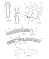
- FIG. 2a The Z-profile of the stiffening element 1 in FIG. 1a is shown in FIG. 2a.
- a ⁇ -shaped profile of a stiffening element 1 is further shown in FIG. 2b.
- FIG. 2c is illustrated a L-profile of a stiffening element 1 according to a second embodiment.
- Both the web 3 and the first flange 5 (fixation flange) have a curvature corresponding essentially with the curvature of the curved shell inner surface, which according to this embodiment corresponds with a moderate double curved surface 9', seen in a direction transverse to the surface.
- FIG. 2d shows schematically a flattened ⁇ -profile of a stiffening element structure 21 (also shown in FIG. 6a).
- the moderate double curved surface 9' comprises surfaces including surfaces with double curvature small enough such that it is possible to wrap a flat blank (lay-up of plastic) on a tool surface without wrinkling the blank.
- Fig. 2e shows a flat blank 19 provided for a stiffening element 1 with the profile shown in FIG. 2c.
- FIG. 3a illustrates an aircraft door 23 (a panel) including the embodiment shown in FIG. 1 forming a stiffening element structure 21.
- To the door shell inner surface 9 are attached eight stiffening elements 1 by means of glue (may also be welded, riveted or screwed).
- An arrangement of in pairs placed stiffening elements 1', 1 stiffens the curved shell surface 9 of the door 23.
- Each pair comprises a first stiffening element 1' arranged adjacent a second stiffening element 1".
- the inner flanges 7 of each pair are faced towards each other.
- Each pair constitutes the stiffening element structure 21.
- FIG. 3b shows the aircraft door 23 in a side view.
- a bracing means 25 (a cross bar) is attached (provided) between the stiffening elements 1', 1" forming the stiffening element structure 21,
- FIG. 4 illustrates a part of a forming tool 27 comprising a forming surface 29.
- the forming tool 27 includes a male forming part 28 and a female forming part 31.
- the stiffening element forming surface 29 of the male forming part 28 and the female forming part 31 respectively comprises a first folding (curving) line 33.
- the blank 19 (see FIG. 1b) is to be applied between the forming surfaces 29 of male and female forming parts of the forming tool 27.
- the first folding edge 33 is formed for providing the first folding line 13 at the blank 19.
- the first folding edge 33 has a folding direction alteration in the first and second plane in a similar way as being described above.
- an intersection line can be defined corresponding to an extension between the curved shell surface 9 and the same surface imaginary rotated with a desired angle, wherein said angle corresponds to a desired angel of the web 3 of the stiffening element for manufacturing.
- the intersection line equals the three-dimensional folding edge 33 (corresponding with the first folding line 13) for folding a flat blank of plastic into said stiffening element.
- the curved shell surface is in this embodiment a single curved shell surface 9.
- the blank 19 is formed and folded along the first folding edge 33 in the first p' and second p" plane.
- the first folding edge 33 has in the first plane p' a varying folding direction essentially corresponding with the curvature of the curved shell surface 9.
- the first folding edge 33 has in the second plane p" a varying folding direction corresponding with the folding curvature in the first plane p'.
- the same relationship is valid for a second folding edge 35. That is, the curvature of the first folding edge 33 is the same as the curvature (that is; parallel with) of the second folding edge 35.
- a web forming surface 37 and an outer 39 and inner 41 flange forming surface of the forming tool 27 hold and guide the blank 19 during the folding procedure and accomplish the forming of the web 3, the outer flange 5 and the inner flange 7 of the stiffening element 1.
- the procedure is as follows: The completely folded blank 19 is sealed in a vacuum bag (not shown). Thereafter air is evacuated from the vacuum bag. Thereafter the completely folded blank 19 is heated by means of heating means (not shown). Thereafter it is cooled and being stripped from the vacuum bag. The stiffening element 1 is ready for attachment, after it has been removed from the forming tool 27, to the single curved shell surface 9.
- the blank 19 may be cured in an autoclave (not shown) for compressing the completely formed blank 19 so that eventual air pockets between the plastic layers can be minimized and limited to a certain predetermined extension.
- FIG. 5 illustrates schematically in a perspective view a stiffening element 2 according to a third embodiment of the present invention.
- the stiffening element 2 of this embodiment is manufactured of a blank 19 of plastic without reinforcement fibres.
- the blank 19 prior folding was square-shaped.
- the stiffening element 2 comprises a first folding line 13 between a web 3 and a flange 5.
- the first folding line 13 has a folding direction alteration in a first p' and a second p" plane.
- the first folding line 13 in the first plane p' has a varying folding direction a' corresponding essentially with the curved shell surface 9.
- the first folding line 13 has in the second plane p" a varying folding direction a" corresponding with the varying folding direction a' in the first plane p'.
- the varying folding direction a corresponds essentially with the mean radius R of the curved shell surface 9 and corresponds essentially with a' and a".
- FIG. 6a illustrates a further stiffening element structure 21.
- Two stiffening elements 1', 1" are provided adjacent with their ends 43 nearest each other.
- the inner flanges of each pair of stiffening elements are faced towards each other and a bracing means 25 (a plate) is attached to the inner flanges 7.
- FIG. 6b illustrates a further stiffening element structure 21.
- Two stiffening elements 1', 1" are provided adjacent with their waists 45 nearest each other.
- a bracing plate 25 connects the two stiffening elements 1', 1".
- the bracing plate in FIG. 6b is lighter (less weight) than that shown in FIG. 6a.
- FIG. 7a and 7b illustrate two working stages of a method of providing the substantial flat blank 19 of plastic layers by means of an automatic tape laying machine 47 (ATLM).
- ATLM automatic tape laying machine 47
- FIG. 7a is schematically shown a prepreg tape reel arrangement 49 being moved in an direction essentially parallel (or along the 0-line) with the extension line 51 of the blank 19.
- a reel arrangement 49 applies a prepreg tape 53 in sections 55 in a first layer.
- Reinforcement elements 57 (glass fibres) are schematically marked with lines F.
- FIG. 7b is schematically shown the prepreg tape reel arrangement 49 in another position for laying prepreg tape 53 onto the first layer with a 90 degrees change. That is, the reinforcement fibres of the now applied plastic layer will have a 90 degrees altered direction relative the previous applied layer.
- the automatic tape laying machine 47 in FIGS 7a and 7b has provided the blank 19 in FIG. 1b including 8 plastic layers (not shown).
- the fibre orientation is 0, 90, +45, -45, -45, +45, 90 and 0 degrees.
- Other blanks may have up to 120 layers.
- FIG. 8a shows schematically a curvature 109 of an imaginary surface 108.
- the imaginary surface 108 is shown in FIG. 8b.
- FIG. 8b is also shown (for definition of curvature relationship) desired first and second point 110, 111 on the imaginary surface 108.
- a rotation line 112 connects the first and second points 110, 111.
- a rotation of the imaginary surface 108 with a desired angle 113 around the rotation line 112 generates a rotated imaginary surface 114.
- the intersection between the imaginary surface 108 and the rotated imaginary surface 114 is marked with a dotted intersection line 115.
- the intersection line 115 equals a three-dimensional folding line for folding the flat lay-up (the flat blank 19) for creating a fixation flange (first flange 5) and the web 3, the fixation flange has a curvature corresponding with the curvature of the curved shell surface 9.
- FIG. 8d is shown the curvature 109 of the imaginary surface 108 with the first and second points 110, 111, between the points is defined the straight rotation line 112.
- a midpoint 116 is defined on the rotation line 112 and between the first and second point 110, 111.
- the midpoint 116 is projected on the imaginary surface 108 creating a first projection point 117 normal to the rotation line 112.
- This first projecting point 117 is thereafter translated normal to the imaginary surface 108, wherein a desired length of the web creates a second point 118.
- the imaginary surface 108 is thereby transformed from the first projections point 117 to the second point 118 creating the flange surface 119.
- the intersection curve between the flange surface 119 and a web surface 120 can be altered slightly to give new characteristics to the flange in respect to a local angle 113', the flange height H and other characteristics, although these characteristics are connected thereto.
- the flange surface 119 may correspond with a surface such as the single curved shell surface 9 in FIG. 1 a or a moderate double curved surface.
- Such a moderate double curved surface is defined as surfaces with double curvature small enough to make it possible to wrap a flat lay-up on surface without wrinkling.
- the present invention is of course not in any way restricted to the preferred embodiments described above, but many possibilities to modifications or combinations of the described embodiments thereof should be apparent to a person with ordinary skill in the art without departing from the basic idea of the invention as defined in the appended claims.
- the plastic can be thermo setting plastic, epoxi resins, thermoplastics, polyester resins, fibreglass reinforced plastics etc.
- the word folding in the present application can be replaced by the words bending, curving etc. Folds along the folding lines of the stiffening element are understood to be provided essentially rounded, also where the figures show sharp folds or sharp folds.
- the second folding line can be modified in different ways in respect to the first folding line.
- the first folding line must not have the same radius of curvature, but can be slightly changed in respect to the first folding line, thereby achieving that the web will have different angles relatively to the plane of the shell surface. This is advantageously when manufacturing other surfaces than single curved shell surfaces with stiffening elements, such as stiffening moderate double curved shell surfaces with stiffening elements.
- the invention is particularly, but not exclusively, applicable to larger aircraft such as passenger carrying aircraft or freight carrying aircraft.
Priority Applications (5)
| Application Number | Priority Date | Filing Date | Title |
|---|---|---|---|
| EP05112454A EP1800840B1 (fr) | 2005-12-20 | 2005-12-20 | Raidisseur et procédé pour sa fabrication |
| DE602005010106T DE602005010106D1 (de) | 2005-12-20 | 2005-12-20 | Versteifungselement und Verfahren zu dessen Herstellung |
| ES05112454T ES2314581T3 (es) | 2005-12-20 | 2005-12-20 | Elemento de rigidizacion y procedimiento de fabricacion de un elemento de rigidizacion. |
| AT05112454T ATE409577T1 (de) | 2005-12-20 | 2005-12-20 | Versteifungselement und verfahren zu dessen herstellung |
| US11/611,901 US20070161483A1 (en) | 2005-12-20 | 2006-12-18 | Stiffening element and a method for manufacturing of a stiffening elememt |
Applications Claiming Priority (1)
| Application Number | Priority Date | Filing Date | Title |
|---|---|---|---|
| EP05112454A EP1800840B1 (fr) | 2005-12-20 | 2005-12-20 | Raidisseur et procédé pour sa fabrication |
Publications (2)
| Publication Number | Publication Date |
|---|---|
| EP1800840A1 true EP1800840A1 (fr) | 2007-06-27 |
| EP1800840B1 EP1800840B1 (fr) | 2008-10-01 |
Family
ID=35962170
Family Applications (1)
| Application Number | Title | Priority Date | Filing Date |
|---|---|---|---|
| EP05112454A Not-in-force EP1800840B1 (fr) | 2005-12-20 | 2005-12-20 | Raidisseur et procédé pour sa fabrication |
Country Status (5)
| Country | Link |
|---|---|
| US (1) | US20070161483A1 (fr) |
| EP (1) | EP1800840B1 (fr) |
| AT (1) | ATE409577T1 (fr) |
| DE (1) | DE602005010106D1 (fr) |
| ES (1) | ES2314581T3 (fr) |
Cited By (9)
| Publication number | Priority date | Publication date | Assignee | Title |
|---|---|---|---|---|
| WO2009037647A2 (fr) * | 2007-09-20 | 2009-03-26 | Alenia Aeronautica S.P.A. | Procédé de fabrication d'un élément de structure incurvé en matériau composite à section ouverte complexe |
| WO2009088699A1 (fr) | 2008-01-09 | 2009-07-16 | The Boeing Company | Pièces composites profilées |
| WO2009129007A2 (fr) | 2008-04-17 | 2009-10-22 | The Boeing Company | Procede de production de structures composites profilees et structures ainsi produites |
| US8349105B2 (en) | 2008-04-17 | 2013-01-08 | The Boeing Company | Curved composite frames and method of making the same |
| US8632653B2 (en) | 2005-05-03 | 2014-01-21 | The Boeing Company | Method of manufacturing curved composite structural elements |
| US8932423B2 (en) | 2008-04-17 | 2015-01-13 | The Boeing Company | Method for producing contoured composite structures and structures produced thereby |
| US9278484B2 (en) | 2008-04-17 | 2016-03-08 | The Boeing Company | Method and apparatus for producing contoured composite structures and structures produced thereby |
| US10054206B2 (en) | 2014-03-20 | 2018-08-21 | Schaeffler Technologies AG & Co. KG | Turbine shell with integrated stiffening elements |
| WO2022245546A1 (fr) * | 2021-05-20 | 2022-11-24 | Schaeffler Technologies AG & Co. KG | Roue à aubes piquées et convertisseur de couple comprenant une roue à aubes piquées |
Families Citing this family (15)
| Publication number | Priority date | Publication date | Assignee | Title |
|---|---|---|---|---|
| US7943076B1 (en) * | 2005-05-03 | 2011-05-17 | The Boeing Company | Method of manufacturing curved composite structural elements |
| BRPI0823282A2 (pt) * | 2008-11-13 | 2015-06-16 | Saab Ab | Método de formação de um artigo compósito |
| DE102010044584A1 (de) * | 2010-09-07 | 2012-03-08 | Kautex Textron Gmbh & Co. Kg | Kraftstoffbehälter aus thermoplastischem Kunststoff |
| US9701067B2 (en) | 2010-11-12 | 2017-07-11 | The Boeing Company | Method of laying up prepreg plies on contoured tools using a deformable carrier film |
| US9387657B2 (en) | 2010-11-12 | 2016-07-12 | The Boeing Company | Method of fabricating a curved composite structure using composite prepreg tape |
| US8551380B2 (en) * | 2010-11-12 | 2013-10-08 | The Boeing Company | Method of laying up prepreg plies on contoured tools using a deformable carrier film |
| US9545757B1 (en) * | 2012-02-08 | 2017-01-17 | Textron Innovations, Inc. | Composite lay up and method of forming |
| IL223443A (en) | 2012-12-04 | 2014-06-30 | Elbit Systems Cyclone Ltd | Buildings from composite materials with integral composite connectors and manufacturing methods |
| FR3009273B1 (fr) * | 2013-07-30 | 2017-07-28 | Eurocopter France | Cadre en materiaux composites stratifies pour fuselage d'aeronef, comportant des zones de renfort courbes a rayon de courbure evolutif |
| GB201508375D0 (en) * | 2015-05-15 | 2015-07-01 | Airbus Operations Ltd | Method of forming composite structures |
| US10005267B1 (en) | 2015-09-22 | 2018-06-26 | Textron Innovations, Inc. | Formation of complex composite structures using laminate templates |
| DE102016109284B3 (de) * | 2016-05-20 | 2017-03-23 | Cotesa Gmbh | Bogenförmige Faserverbundkunststoff-Preform und Verfahren zur Herstellung gekrümmter Profile |
| US11318689B2 (en) | 2018-12-21 | 2022-05-03 | The Boeing Company | Ply transporting and compacting apparatus and method therefor |
| US11305498B2 (en) | 2018-12-21 | 2022-04-19 | The Boeing Company | System and method for fabricating a composite ply layup |
| ES2958761T3 (es) * | 2019-11-13 | 2024-02-14 | Airbus Operations Slu | Dispositivo y método de formación de un laminado compuesto para obtener un perfil en forma de Z |
Citations (2)
| Publication number | Priority date | Publication date | Assignee | Title |
|---|---|---|---|---|
| EP1151850A2 (fr) | 2000-05-01 | 2001-11-07 | Honda Giken Kogyo Kabushiki Kaisha | Procédé pour la fabrication d'un produit semi-durci renforcé par des fibres avec un bord en gradin, et procédé de fabrication d'une structure préformée en utilisant ce produit |
| EP1547756A1 (fr) | 2003-12-24 | 2005-06-29 | Airbus UK Limited | Méthode de fabrication de pièces d'avion |
Family Cites Families (10)
| Publication number | Priority date | Publication date | Assignee | Title |
|---|---|---|---|---|
| US3936277A (en) * | 1970-04-09 | 1976-02-03 | Mcdonnell Douglas Corporation | Aluminum alloy-boron fiber composite |
| US4777005A (en) * | 1986-02-03 | 1988-10-11 | The Board Of Trustees Of The Leland Stanford Junior University | Process for shaping fiber composite materials |
| US5358583A (en) * | 1988-10-19 | 1994-10-25 | E. I. Du Pont De Nemours And Company | Apparatus and method for shaping fiber reinforced resin matrix materials and product thereof |
| US5484277A (en) * | 1989-12-26 | 1996-01-16 | Mcdonnell Douglas Corporation | Mandreless molding system |
| US5648109A (en) * | 1995-05-03 | 1997-07-15 | Massachusetts Institute Of Technology | Apparatus for diaphragm forming |
| FR2766407B1 (fr) * | 1997-07-22 | 1999-10-15 | Aerospatiale | Procede de fabrication de pieces de grandes dimensions en materiau composite a matrice thermoplastique, telles que des troncons de fuselage d'aeronefs |
| US6553734B1 (en) * | 2000-08-24 | 2003-04-29 | Lockheed Martin Corporation | Composite structural panel with undulated body |
| US7204951B2 (en) * | 2002-07-30 | 2007-04-17 | Rocky Mountain Composites, Inc. | Method of assembling a single piece co-cured structure |
| US7249943B2 (en) * | 2003-08-01 | 2007-07-31 | Alliant Techsystems Inc. | Apparatus for forming composite stiffeners and reinforcing structures |
| US8632653B2 (en) * | 2005-05-03 | 2014-01-21 | The Boeing Company | Method of manufacturing curved composite structural elements |
-
2005
- 2005-12-20 AT AT05112454T patent/ATE409577T1/de not_active IP Right Cessation
- 2005-12-20 ES ES05112454T patent/ES2314581T3/es active Active
- 2005-12-20 DE DE602005010106T patent/DE602005010106D1/de active Active
- 2005-12-20 EP EP05112454A patent/EP1800840B1/fr not_active Not-in-force
-
2006
- 2006-12-18 US US11/611,901 patent/US20070161483A1/en not_active Abandoned
Patent Citations (2)
| Publication number | Priority date | Publication date | Assignee | Title |
|---|---|---|---|---|
| EP1151850A2 (fr) | 2000-05-01 | 2001-11-07 | Honda Giken Kogyo Kabushiki Kaisha | Procédé pour la fabrication d'un produit semi-durci renforcé par des fibres avec un bord en gradin, et procédé de fabrication d'une structure préformée en utilisant ce produit |
| EP1547756A1 (fr) | 2003-12-24 | 2005-06-29 | Airbus UK Limited | Méthode de fabrication de pièces d'avion |
Cited By (20)
| Publication number | Priority date | Publication date | Assignee | Title |
|---|---|---|---|---|
| US9630390B2 (en) | 2005-05-03 | 2017-04-25 | The Boeing Company | Method of manufacturing curved composite structural elements |
| US8632653B2 (en) | 2005-05-03 | 2014-01-21 | The Boeing Company | Method of manufacturing curved composite structural elements |
| WO2009037647A3 (fr) * | 2007-09-20 | 2009-09-11 | Alenia Aeronautica S.P.A. | Procédé de fabrication d'un élément de structure incurvé en matériau composite à section ouverte complexe |
| WO2009037647A2 (fr) * | 2007-09-20 | 2009-03-26 | Alenia Aeronautica S.P.A. | Procédé de fabrication d'un élément de structure incurvé en matériau composite à section ouverte complexe |
| US8419875B2 (en) | 2007-09-20 | 2013-04-16 | Alenia Aeronautica S.P.A. | Method of manufacturing a curved structural element made of composite material and having a complex, open cross-section |
| US8535784B2 (en) | 2008-01-09 | 2013-09-17 | The Boeing Company | Contoured composite parts |
| WO2009088699A1 (fr) | 2008-01-09 | 2009-07-16 | The Boeing Company | Pièces composites profilées |
| CN101883674B (zh) * | 2008-01-09 | 2014-11-12 | 波音公司 | 轮廓复合件 |
| US8152948B2 (en) | 2008-01-09 | 2012-04-10 | The Boeing Company | Contoured composite parts |
| JP2011518068A (ja) * | 2008-04-17 | 2011-06-23 | ザ・ボーイング・カンパニー | 輪郭に合致した複合構造物を生産する方法及びその方法によって生産される構造物 |
| US8349105B2 (en) | 2008-04-17 | 2013-01-08 | The Boeing Company | Curved composite frames and method of making the same |
| WO2009129007A3 (fr) * | 2008-04-17 | 2009-12-30 | The Boeing Company | Procede de production de structures composites profilees et structures ainsi produites |
| US8932423B2 (en) | 2008-04-17 | 2015-01-13 | The Boeing Company | Method for producing contoured composite structures and structures produced thereby |
| US9090028B2 (en) | 2008-04-17 | 2015-07-28 | The Boeing Company | Method for producing contoured composite structures and structures produced thereby |
| US9096305B2 (en) | 2008-04-17 | 2015-08-04 | The Boeing Company | Curved composite frames and method of making the same |
| US9278484B2 (en) | 2008-04-17 | 2016-03-08 | The Boeing Company | Method and apparatus for producing contoured composite structures and structures produced thereby |
| WO2009129007A2 (fr) | 2008-04-17 | 2009-10-22 | The Boeing Company | Procede de production de structures composites profilees et structures ainsi produites |
| EP2386483A3 (fr) * | 2010-05-10 | 2017-05-03 | The Boeing Company | Cadres composites incurvés et leur procédé de fabrication |
| US10054206B2 (en) | 2014-03-20 | 2018-08-21 | Schaeffler Technologies AG & Co. KG | Turbine shell with integrated stiffening elements |
| WO2022245546A1 (fr) * | 2021-05-20 | 2022-11-24 | Schaeffler Technologies AG & Co. KG | Roue à aubes piquées et convertisseur de couple comprenant une roue à aubes piquées |
Also Published As
| Publication number | Publication date |
|---|---|
| EP1800840B1 (fr) | 2008-10-01 |
| US20070161483A1 (en) | 2007-07-12 |
| ES2314581T3 (es) | 2009-03-16 |
| ATE409577T1 (de) | 2008-10-15 |
| DE602005010106D1 (de) | 2008-11-13 |
Similar Documents
| Publication | Publication Date | Title |
|---|---|---|
| EP1800840B1 (fr) | Raidisseur et procédé pour sa fabrication | |
| EP2091811B1 (fr) | Barre de cisaillement composite | |
| US8398910B2 (en) | Method for manufacturing a fibre-composite component, fibre-composite component and fibre-composite fuselage component of an aircraft | |
| US5843355A (en) | Method for molding a thermoplastic composite sine wave spar structure | |
| EP2152496B1 (fr) | Procede de fabrication d'un objet a partir d'une structure du type sandwich ayant un coin renforce et objet de ce type | |
| EP1800842B1 (fr) | Procédé pour la fabrication d'un élément structural allongé configuré pour la rigidification d'un panneau et un procédé pour la fabrication d'un panneau rigide avec un élément de rigidification allongé | |
| EP2789534B1 (fr) | Longeron d'aile à plusieurs carters et revêtement | |
| EP2318466B1 (fr) | Methode de fabrication de structure composite et structure composite intermediaire | |
| US20030042364A1 (en) | Method of manufacturing a composite material wing and a composite material wing | |
| JP6778817B2 (ja) | 複合材成形治具及び複合材成形方法 | |
| CA2685478A1 (fr) | Caisson de torsion multi-longerons integre en materiau composite | |
| EP1800841B1 (fr) | Raidisseur et procédé pour sa fabrication | |
| EP3626603B1 (fr) | Longeron d'aile en tissu composite comportant des nappes de sommet à bande entrelacée | |
| US8580170B2 (en) | Process for producing a substantially shell-shaped component | |
| CN111452947A (zh) | 成形复合桁条 | |
| US20080268208A1 (en) | Complex geometries made of composite material and forming process for same | |
| EP3894190A1 (fr) | Améliorations apportées à la fabrication de pales d'éolienne | |
| US20090025865A1 (en) | Method and apparatus for manufacturing of a wing spar profile element | |
| EP2888095B1 (fr) | Structure renforcée et procédé pour la fabrication d'une structure renforcée | |
| EP3787885B1 (fr) | Procédé pour fabrication d'une bride d'âme de cisaillement | |
| CA3075539A1 (fr) | Station pour former des composites |
Legal Events
| Date | Code | Title | Description |
|---|---|---|---|
| PUAI | Public reference made under article 153(3) epc to a published international application that has entered the european phase |
Free format text: ORIGINAL CODE: 0009012 |
|
| AK | Designated contracting states |
Kind code of ref document: A1 Designated state(s): AT BE BG CH CY CZ DE DK EE ES FI FR GB GR HU IE IS IT LI LT LU LV MC NL PL PT RO SE SI SK TR |
|
| AX | Request for extension of the european patent |
Extension state: AL BA HR MK YU |
|
| 17P | Request for examination filed |
Effective date: 20070709 |
|
| 17Q | First examination report despatched |
Effective date: 20070813 |
|
| AKX | Designation fees paid |
Designated state(s): AT BE BG CH CY CZ DE DK EE ES FI FR GB GR HU IE IS IT LI LT LU LV MC NL PL PT RO SE SI SK TR |
|
| GRAP | Despatch of communication of intention to grant a patent |
Free format text: ORIGINAL CODE: EPIDOSNIGR1 |
|
| GRAS | Grant fee paid |
Free format text: ORIGINAL CODE: EPIDOSNIGR3 |
|
| GRAA | (expected) grant |
Free format text: ORIGINAL CODE: 0009210 |
|
| AK | Designated contracting states |
Kind code of ref document: B1 Designated state(s): AT BE BG CH CY CZ DE DK EE ES FI FR GB GR HU IE IS IT LI LT LU LV MC NL PL PT RO SE SI SK TR |
|
| REG | Reference to a national code |
Ref country code: GB Ref legal event code: FG4D |
|
| REG | Reference to a national code |
Ref country code: CH Ref legal event code: EP |
|
| REG | Reference to a national code |
Ref country code: IE Ref legal event code: FG4D |
|
| REF | Corresponds to: |
Ref document number: 602005010106 Country of ref document: DE Date of ref document: 20081113 Kind code of ref document: P |
|
| PG25 | Lapsed in a contracting state [announced via postgrant information from national office to epo] |
Ref country code: SI Free format text: LAPSE BECAUSE OF FAILURE TO SUBMIT A TRANSLATION OF THE DESCRIPTION OR TO PAY THE FEE WITHIN THE PRESCRIBED TIME-LIMIT Effective date: 20081001 |
|
| REG | Reference to a national code |
Ref country code: ES Ref legal event code: FG2A Ref document number: 2314581 Country of ref document: ES Kind code of ref document: T3 |
|
| NLV1 | Nl: lapsed or annulled due to failure to fulfill the requirements of art. 29p and 29m of the patents act | ||
| PG25 | Lapsed in a contracting state [announced via postgrant information from national office to epo] |
Ref country code: BG Free format text: LAPSE BECAUSE OF FAILURE TO SUBMIT A TRANSLATION OF THE DESCRIPTION OR TO PAY THE FEE WITHIN THE PRESCRIBED TIME-LIMIT Effective date: 20090101 Ref country code: LT Free format text: LAPSE BECAUSE OF FAILURE TO SUBMIT A TRANSLATION OF THE DESCRIPTION OR TO PAY THE FEE WITHIN THE PRESCRIBED TIME-LIMIT Effective date: 20081001 Ref country code: AT Free format text: LAPSE BECAUSE OF FAILURE TO SUBMIT A TRANSLATION OF THE DESCRIPTION OR TO PAY THE FEE WITHIN THE PRESCRIBED TIME-LIMIT Effective date: 20081001 |
|
| PG25 | Lapsed in a contracting state [announced via postgrant information from national office to epo] |
Ref country code: PL Free format text: LAPSE BECAUSE OF FAILURE TO SUBMIT A TRANSLATION OF THE DESCRIPTION OR TO PAY THE FEE WITHIN THE PRESCRIBED TIME-LIMIT Effective date: 20081001 Ref country code: PT Free format text: LAPSE BECAUSE OF FAILURE TO SUBMIT A TRANSLATION OF THE DESCRIPTION OR TO PAY THE FEE WITHIN THE PRESCRIBED TIME-LIMIT Effective date: 20090302 Ref country code: NL Free format text: LAPSE BECAUSE OF FAILURE TO SUBMIT A TRANSLATION OF THE DESCRIPTION OR TO PAY THE FEE WITHIN THE PRESCRIBED TIME-LIMIT Effective date: 20081001 Ref country code: FI Free format text: LAPSE BECAUSE OF FAILURE TO SUBMIT A TRANSLATION OF THE DESCRIPTION OR TO PAY THE FEE WITHIN THE PRESCRIBED TIME-LIMIT Effective date: 20081001 Ref country code: LV Free format text: LAPSE BECAUSE OF FAILURE TO SUBMIT A TRANSLATION OF THE DESCRIPTION OR TO PAY THE FEE WITHIN THE PRESCRIBED TIME-LIMIT Effective date: 20081001 Ref country code: IS Free format text: LAPSE BECAUSE OF FAILURE TO SUBMIT A TRANSLATION OF THE DESCRIPTION OR TO PAY THE FEE WITHIN THE PRESCRIBED TIME-LIMIT Effective date: 20090201 |
|
| PG25 | Lapsed in a contracting state [announced via postgrant information from national office to epo] |
Ref country code: MC Free format text: LAPSE BECAUSE OF NON-PAYMENT OF DUE FEES Effective date: 20081231 Ref country code: EE Free format text: LAPSE BECAUSE OF FAILURE TO SUBMIT A TRANSLATION OF THE DESCRIPTION OR TO PAY THE FEE WITHIN THE PRESCRIBED TIME-LIMIT Effective date: 20081001 Ref country code: RO Free format text: LAPSE BECAUSE OF FAILURE TO SUBMIT A TRANSLATION OF THE DESCRIPTION OR TO PAY THE FEE WITHIN THE PRESCRIBED TIME-LIMIT Effective date: 20081001 Ref country code: BE Free format text: LAPSE BECAUSE OF FAILURE TO SUBMIT A TRANSLATION OF THE DESCRIPTION OR TO PAY THE FEE WITHIN THE PRESCRIBED TIME-LIMIT Effective date: 20081001 Ref country code: DK Free format text: LAPSE BECAUSE OF FAILURE TO SUBMIT A TRANSLATION OF THE DESCRIPTION OR TO PAY THE FEE WITHIN THE PRESCRIBED TIME-LIMIT Effective date: 20081001 |
|
| PLBE | No opposition filed within time limit |
Free format text: ORIGINAL CODE: 0009261 |
|
| STAA | Information on the status of an ep patent application or granted ep patent |
Free format text: STATUS: NO OPPOSITION FILED WITHIN TIME LIMIT |
|
| PG25 | Lapsed in a contracting state [announced via postgrant information from national office to epo] |
Ref country code: CZ Free format text: LAPSE BECAUSE OF FAILURE TO SUBMIT A TRANSLATION OF THE DESCRIPTION OR TO PAY THE FEE WITHIN THE PRESCRIBED TIME-LIMIT Effective date: 20081001 Ref country code: SE Free format text: LAPSE BECAUSE OF FAILURE TO SUBMIT A TRANSLATION OF THE DESCRIPTION OR TO PAY THE FEE WITHIN THE PRESCRIBED TIME-LIMIT Effective date: 20090101 |
|
| 26N | No opposition filed |
Effective date: 20090702 |
|
| REG | Reference to a national code |
Ref country code: IE Ref legal event code: MM4A |
|
| PG25 | Lapsed in a contracting state [announced via postgrant information from national office to epo] |
Ref country code: SK Free format text: LAPSE BECAUSE OF FAILURE TO SUBMIT A TRANSLATION OF THE DESCRIPTION OR TO PAY THE FEE WITHIN THE PRESCRIBED TIME-LIMIT Effective date: 20081001 |
|
| PG25 | Lapsed in a contracting state [announced via postgrant information from national office to epo] |
Ref country code: IE Free format text: LAPSE BECAUSE OF NON-PAYMENT OF DUE FEES Effective date: 20081220 |
|
| PG25 | Lapsed in a contracting state [announced via postgrant information from national office to epo] |
Ref country code: LU Free format text: LAPSE BECAUSE OF NON-PAYMENT OF DUE FEES Effective date: 20081220 Ref country code: HU Free format text: LAPSE BECAUSE OF FAILURE TO SUBMIT A TRANSLATION OF THE DESCRIPTION OR TO PAY THE FEE WITHIN THE PRESCRIBED TIME-LIMIT Effective date: 20090402 Ref country code: CY Free format text: LAPSE BECAUSE OF FAILURE TO SUBMIT A TRANSLATION OF THE DESCRIPTION OR TO PAY THE FEE WITHIN THE PRESCRIBED TIME-LIMIT Effective date: 20081001 |
|
| REG | Reference to a national code |
Ref country code: CH Ref legal event code: PL |
|
| PG25 | Lapsed in a contracting state [announced via postgrant information from national office to epo] |
Ref country code: TR Free format text: LAPSE BECAUSE OF FAILURE TO SUBMIT A TRANSLATION OF THE DESCRIPTION OR TO PAY THE FEE WITHIN THE PRESCRIBED TIME-LIMIT Effective date: 20081001 |
|
| PG25 | Lapsed in a contracting state [announced via postgrant information from national office to epo] |
Ref country code: LI Free format text: LAPSE BECAUSE OF NON-PAYMENT OF DUE FEES Effective date: 20091231 Ref country code: GR Free format text: LAPSE BECAUSE OF FAILURE TO SUBMIT A TRANSLATION OF THE DESCRIPTION OR TO PAY THE FEE WITHIN THE PRESCRIBED TIME-LIMIT Effective date: 20090102 Ref country code: CH Free format text: LAPSE BECAUSE OF NON-PAYMENT OF DUE FEES Effective date: 20091231 |
|
| PGFP | Annual fee paid to national office [announced via postgrant information from national office to epo] |
Ref country code: GB Payment date: 20141229 Year of fee payment: 10 |
|
| PGFP | Annual fee paid to national office [announced via postgrant information from national office to epo] |
Ref country code: DE Payment date: 20141222 Year of fee payment: 10 Ref country code: ES Payment date: 20141222 Year of fee payment: 10 |
|
| PGFP | Annual fee paid to national office [announced via postgrant information from national office to epo] |
Ref country code: FR Payment date: 20141231 Year of fee payment: 10 |
|
| PGFP | Annual fee paid to national office [announced via postgrant information from national office to epo] |
Ref country code: IT Payment date: 20141223 Year of fee payment: 10 |
|
| REG | Reference to a national code |
Ref country code: DE Ref legal event code: R119 Ref document number: 602005010106 Country of ref document: DE |
|
| GBPC | Gb: european patent ceased through non-payment of renewal fee |
Effective date: 20151220 |
|
| REG | Reference to a national code |
Ref country code: FR Ref legal event code: ST Effective date: 20160831 |
|
| PG25 | Lapsed in a contracting state [announced via postgrant information from national office to epo] |
Ref country code: GB Free format text: LAPSE BECAUSE OF NON-PAYMENT OF DUE FEES Effective date: 20151220 Ref country code: DE Free format text: LAPSE BECAUSE OF NON-PAYMENT OF DUE FEES Effective date: 20160701 |
|
| PG25 | Lapsed in a contracting state [announced via postgrant information from national office to epo] |
Ref country code: FR Free format text: LAPSE BECAUSE OF NON-PAYMENT OF DUE FEES Effective date: 20151231 |
|
| PG25 | Lapsed in a contracting state [announced via postgrant information from national office to epo] |
Ref country code: IT Free format text: LAPSE BECAUSE OF NON-PAYMENT OF DUE FEES Effective date: 20151220 |
|
| PG25 | Lapsed in a contracting state [announced via postgrant information from national office to epo] |
Ref country code: ES Free format text: LAPSE BECAUSE OF NON-PAYMENT OF DUE FEES Effective date: 20151221 |
|
| REG | Reference to a national code |
Ref country code: ES Ref legal event code: FD2A Effective date: 20180705 |