EP1799296B1 - Implantierbares fixierelement - Google Patents
Implantierbares fixierelement Download PDFInfo
- Publication number
- EP1799296B1 EP1799296B1 EP05787190A EP05787190A EP1799296B1 EP 1799296 B1 EP1799296 B1 EP 1799296B1 EP 05787190 A EP05787190 A EP 05787190A EP 05787190 A EP05787190 A EP 05787190A EP 1799296 B1 EP1799296 B1 EP 1799296B1
- Authority
- EP
- European Patent Office
- Prior art keywords
- fixation element
- pair
- beaks
- fixation
- cut
- Prior art date
- Legal status (The legal status is an assumption and is not a legal conclusion. Google has not performed a legal analysis and makes no representation as to the accuracy of the status listed.)
- Expired - Lifetime
Links
Images






Classifications
-
- A—HUMAN NECESSITIES
- A61—MEDICAL OR VETERINARY SCIENCE; HYGIENE
- A61N—ELECTROTHERAPY; MAGNETOTHERAPY; RADIATION THERAPY; ULTRASOUND THERAPY
- A61N1/00—Electrotherapy; Circuits therefor
- A61N1/02—Details
- A61N1/04—Electrodes
- A61N1/05—Electrodes for implantation or insertion into the body, e.g. heart electrode
Definitions
- the invention relates to an implantable fixation element for anchoring at least one elongate,for instance essentially cylindrical element in human or animal tissue, comprising a pair of first gripper beaks, movable to and from each other so as to enclose this element, and a fixing part, interconnected therewith and destined for engaging the tissue.
- Such a fixation element is known from the published US Patent Application US2003/0,220,678 A1 .
- This known fixation element which is made from spring steel, comprises two beaks of which the respective ends cross each other and merge into the legs of a hairpin spring, so that the beaks are biased with a certain force towards each other.
- This fixation element is used for anchoring flexible elongated and insulated electrical leads to the wall of a stomach; the free ends of the leads come to lie against the wall of the stomach and are connected to a suitable source of electrical stimulating pulses.
- a first fixation element is placed around the pair of leads and in the stomach, lying against the inner wall of the stomach while a second, similar fixation element, also lying against the outer wall of the stomach, is placed around the pair of leads but outside the stomach. In this way the electrodes are anchored there where the enter the stomach.
- fixation element as known from the abovementioned US Patent Application US2003/0,220,678 A1 to anchor the electrical leads as used with a cardial pacemaker to the surrounding tissue but in that case, too, the surgeon must anchor the fixation device by means of stitching wire to the surrounding tissue - with all the drawbacks which this implies -, while, to obtain a correct fixation, the beaks of the fixation device must exercise a quite strong force on the lead which they enclose. As a result of the fact that the fixation device must be made from spring steel to obtain a sufficient pressure there is a very great risk of damage to the insulation of the leads, so that the metal can contact the electrically conducting core thereof, with damaging and, possibly fatal results.
- the invention aims to obviate the above described drawbacks and particularly to provide a fixation element to be made from plastics which in a simple way and with one single operation encloses both the cylindrical element and anchors this to the surrounding tissue.
- This object is achieved according to the invention in that this fixating part comprises at least a pair of second fixation gripper beaks, capable for movement together with the first pair around a common point of rotation for a simultaneous opening and closing thereof and having an open configuration with opposite ends, of which second gripper beaks the ends, during closing, and capable to penetrate the tissue while means are provided to lock the beaks with respect to each other in the closed state.
- both the gripper beaks intended to surround the element to be anchored as well as the fixation grippers which enclose with their sharp ends the tissue it is ensured that in one step the element is enclosed reliably while at the same time this element is reliably anchored to the surrounding tissue.
- An embodiment which can be easily fabricated in an advantageous way is one in which the respective gripper beaks of the first and the second pair respectively are each formed by a first and second respectively hinge arm, hingedly interconnected at one end, each such hinge arm having, starting from the hinge point, a first part-circular cut-out, said first cut-outs defining together the pair of first gripper beaks, with adjoining a second part-circular cut-out, said second cut-outs defining together the second pair of fixation gripper beaks, while, between the first and second cut-outs respectively, interacting catching coupling parts are provided.
- the two hinge arms are made in one piece and each hinge point is made up by a thin strip of flexible material.
- each hinge arm is at its outer side provided with a out-cut to cooperate with a applicator excerting an inwardly directed force thereon.
- a fixation element can be connected detachably to a part of this applicator, such as described in claim 6, resulting into a disposable unit which can be sterilized as such.
- US 4 144 890 discloses a contact device for muscle stimulation,particularly an epicardial electrode,having a pair of spaced-apart prong-like attachment members,and also discloses an applicator tool for positioning same.
- the use of prong-like attachment members on an epicardial electrode is furthermore disclosed in US 2004/0 176 830 A1 ,as well as in US 4 142 530 which describes an epicardial lead with an electrode tip provided with such members.
- the invention is elucidated on the hand of the drawing.
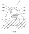
- the fixation element is indicated in its entirety by reference numeral 2; it is made in one piece, for instance by molding, from a suitable plastics and comprises a first arm 4a and a second arm 4b, of which the respective ends 8a, 8b are interconnected hingedly by means of a thin strip of material 6. Both the arms have a first partly circular cut-out 10a, 10b, lying close to the interconnecting point 6, with directly there under a locking mechanism comprising a biased hooking arm 12, protruding from the arm 4b, with the cross-hook 14, cooperating with and a take-up hook 16, protruding from the arm 4a.
- the arms 4a, 4b end in pointed teeth 18a, 18b and there is, between the tooth 18a and the take-up hook 16 as well as between the tooth 18b and the locking hook 12 a second partly circular cut-out, indicated with 20a and 20b, respectively.
- Both the arm 4a and the arm 4b has at the outer circumference a cut-out 22a and 22b, respectively; the purpose thereof will be described later on.
- Fig. 2 shows the fixation element in the closed state, in which the arms 4a, 4b are moved towards each other and the hook end 14 hooks around the take-up hook 16.
- the cut-outs 10a, 10b in combination with the hookarm 12 define between them an essentially cylindrical space in which a schematically indicated element 24,here shown as an elongate circelcylindrical element , can be enclosed while, when the pointed teeth 18a, 18b during the closing of the fixation element had rested with some force on the upper surface of a tissue 26, these teeth have by now penetrated this tissue to a certain depth. In this way the fixation element is anchored to the tissue and the cylindrical element 24, too, is anchored to this tissue.
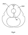
- FIG. 3 shows such a sleeve which comprises two halves 30a, 30b and each halve - see in particular figure 5 - comprises a central hub-shaped part 32a, 32b, bounded by to end flanges 34a1, 34a2 and 34b1, 34b2, respectively.
- the space with a cylindrical cross-section as defined by the hub parts 32a, 32b accommodates the cylindrical element which is to be anchored, thus the flexible insulated lead 36 carrying the electrical pulses.
- fixation element will be attached to the tissue in one operation, namely the movement towards each other of the arms 4a and 4b until the locking elements are intercoupled and the entirety is brought into the closed state, in which the element to be anchored is reliably surrounded and anchored to the tissue in the desired position.
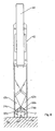
- Exercizing the closing forces is preferably done at the position of the cut-outs 22a, 22b in the arms 4a, 4b and a suitable applicator according to the invention by means of which this can be brought about will be elucidated on the hand of figures 6 to and including 11.
- the housing 42 accommodates slidingly an elongate pressure pin 44 of which during use the upper end 46 must be pressed downwardly and of which the lower end 48 bears on a sliding actuator 50; the lower end 52 thereof is hingedly (at the position 54a, 54b) connected to the upper ends 56a, 56b of two pressure arms 58a, 58b, the narrowing lower ends 60a, 60b thereof merge into two triangular pressure pieces 62a, 62b, each having the shape of an obtuse triangle with long sides and a short basis, 64a, 64b.
- the obtuse points thereof are, at 66, interconnected and beneath this interconnecting point cut-outs 68a, 68b enclose a guide pin 70.
- This guide pin 70 is thus perpendicular to the plane of the drawing and is guided in two narrow, guiding slits 72, which lie in the longitudinal axis of symmetry and are provided in the front and rear wall (perpendicular to the plane of the drawing) of the applicator 40. From each basis 64a, 64b protudes a cam indicated with 74a, 74b, respectively, intended for cooperation with a cut-out 22a, 22b of a fixation element which is to be applicated.
- the front wall 73a and the rear wall 73b of the housing are at the narrowed lower end 77 provided with an entry slit 79, by means of which the applicator is placed around a cylindrical element 76 which is to be put into place while furthermore each of the sidewalls 76a, 76b has an elongated cut-out 78a, 78b, the purpose of which will be described later on.
- the actuator 40, the arms 58a, 58b, interconnected therewith and the two triangular pressure pieces 62a, 62b can be made up in one piece from a suitable plastics, while the hinges 60a, 60b and 68a, 68b consist of parts with a small thickness of the material, so that there a so-called "bending hinge" is obtained.
- Fig. 6 shows the initial position in which the pressure pin 44 protrudes as far as possible from the housing 42, the triangular pressure pieces 62a, 62b have their upper position and the distance between the cams 74a, 74b is at its maximum.
- an - open - fixation element 2 can be supplied into the housing 42, said fixation element 2 being provided with the two sleeve halves 30a, 30b (see figure 3 ).
- the housing 42 is placed with the feeding slit 79 around the cylindrical element 36 which is to be anchored, with the lower end of the housing resting upon the tissue 84 to which the anchoring must take place.
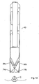
- Fig. 7 shows the respective positions of the various parts in the state in which, by pressing the end of the pressure pin 74, through the actuator 50, the upper ends 56a, 56b of the arms 58a, 58b have just arrowed at the upper ends of the cut-outs 78a, 78b and the hinge pin 70 lies at the lower end of the guide 72.
- the fixation element 2 is not shown.
- Fig. 8 and 9 show how, by pressing the pin 44, the parts have now reached their lowest position, in which the teeth 18a, 18b rest on the tissue 84.
- the fixation element however is not yet closed because the mutual distance of the cams 74a, 74b has not changed.
- the pin 70 has now arrived at the lower end of the guiding slid 72 and as a result the hinge point of the pressure pieces 62a, 62b cannot move further downwardly.
- the shape of the accommodating space can differ from the one which is shown in the drawings, for instance to accommodate an element with a non circular cross-section.
- a fixation element can be interconnected with one of the pressure pieces by means of at least one connection to be ruptured so that it is not necessary to position a loose fixation element in the applicator and as a result one obtains a complete apparatus which is to be used only once.
- two or even more fixation elements can be interconnected and put into place in one operation.
Landscapes
- Health & Medical Sciences (AREA)
- Radiology & Medical Imaging (AREA)
- Animal Behavior & Ethology (AREA)
- Engineering & Computer Science (AREA)
- Biomedical Technology (AREA)
- Nuclear Medicine, Radiotherapy & Molecular Imaging (AREA)
- Cardiology (AREA)
- Life Sciences & Earth Sciences (AREA)
- Heart & Thoracic Surgery (AREA)
- General Health & Medical Sciences (AREA)
- Public Health (AREA)
- Veterinary Medicine (AREA)
- Prostheses (AREA)
- Surgical Instruments (AREA)
- Electrotherapy Devices (AREA)
Claims (6)
- Implantierbares Fixierelement (2) zum Verankern zumindest eines länglichen, beispielsweise im Wesentlichen zylindrischen Elements (24, 36) in menschlichem oder tierischem Gewebe, enthaltend ein Paar erster Greifschnabel (10a, 10b), die zueinander und voneinander weg bewegbar sind, um dieses Element zu umschließen, und enthaltend einen Fixierteil (20a, 20b), der damit verbunden und zum Eingriff in das Gewebe bestimmt ist, dadurch gekennzeichnet, dass dieser Fixierteil zumindest ein Paar zweiter Fixier-Greifschnabel aufweist, die zur gemeinsamen Bewegung mit dem ersten Paar (10a, 10b) um einen gemeinsamen Drehpunkt (6) in der Lage sind, um sich gleichzeitig zu öffnen und zu schließen, und die eine offene Konfiguration mit gegenüberliegenden Enden (18a, 18b) haben, wobei die Enden der zweiten Greifschnabel während des Schließens in der Lage sind, das Gewebe zu durchdringen, während Mittel (14, 16) vorgesehen sind, um die Schnabel im geschlossenen Zustand in Bezug aufeinander zu verriegeln.
- Fixierelement nach Anspruch 1, dadurch gekennzeichnet, dass das erste und das zweite Paar Greifschnabel (10a, 10b) auf der gleichen Seite eines gemeinsamen Drehpunkts liegen.
- Fixierelement nach Anspruch 2, dadurch gekennzeichnet, dass die entsprechenden Greifschnabel (10a, 10b) des ersten bzw. zweiten Paars jeweils durch erste bzw. zweite Gelenkarme (4a, 4b) gebildet sind, die an einem Ende gelenkig miteinander verbunden sind, wobei jeder solcher Gelenkarm ausgehend vom Gelenkpunkt (6) eine erste, teilweise kreisförmige Aussparung (22a, 22b) aufweist, wobei die ersten Aussparungen gemeinsam das Paar erster Greifschnabel definieren, wobei angrenzend eine zweite, teilweise kreisförmige Aussparung vorgesehen ist, wobei die zweiten Aussparungen gemeinsam das zweite Paar Fixier-Greifschnabel definieren, während zusammenwirkende Rast-Verbindungselemente (22a, 22b) zwischen den ersten bzw. zweiten Aussparungen vorgesehen sind.
- Fixierelement nach Anspruch 3, dadurch gekennzeichnet, dass die beiden Gelenkarme (4a, 4b) einstückig hergestellt sind, und jeder Gelenkpunkt (6) aus einem dünnen Streifen aus flexiblem Material besteht.
- Fixierelement nach Anspruch 3 und 4, dadurch gekennzeichnet, dass jeder Gelenkarm (4a, 4b) an seiner Außenseite mit einer Aussparung versehen ist, um mit einem Applikator zusammenzuwirken, der eine nach innen gerichtete Kraft auf diese ausübt.
- System, mit:- einem Fixierelement nach einem der Ansprüche 3 bis 5;- einen in Kombination mit dem Fixierelement zu verwendenden Applikator, der ein längliches Gehäuse mit einem Bedienelement aufweist, das in Längsrichtung des Gehäuses verschiebbar und mit einem Aktuator verbunden ist, der ebenfalls in Längsrichtung des Gehäuses verschiebbar ist, wobei der Aktuator mit einem Mittelteil auf die Verbindungsstelle der ersten Enden von zwei Druckarmen wirkt, wobei die Druckarme einen stumpfen Winkel aufweisen und sich die zweiten Enden davon, die in einer Richtung normal zur Gehäuseachse in einem Abstand zueinander liegen, durch Aussparungen in den Gehäusewänden nach außen bewegen können, und die jeweils einen Druck auf eine Spitze eines im Wesentlichen dreieckigen Druckstücks ausüben, wobei die jeweiligen stumpfen Basispunkte davon miteinander gelenkmäßig verbunden und über eine begrenzte Distanz bewegbar sind, wobei sie im Gehäuse in Längsrichtung davon geführt werden, wobei jedes Druckstück neben dem anderen Basispunkt zum Zusammenwirken mit einem zu applizierenden Fixierelement vorgesehen ist, während das untere Ende des Gehäuses einen Raum zur Aufnahme eines zu applizierenden Fixierelements aufweist,wobei das Fixierelement über eine Rupturverbindung mit zumindest einem der Druckstücke des Applikators verbunden ist.
Applications Claiming Priority (2)
| Application Number | Priority Date | Filing Date | Title |
|---|---|---|---|
| NL1027131A NL1027131C2 (nl) | 2004-09-28 | 2004-09-28 | Implanteerbaar verankeringssysteem. |
| PCT/NL2005/000670 WO2006036058A2 (en) | 2004-09-28 | 2005-09-14 | Implantable fixation element |
Publications (2)
| Publication Number | Publication Date |
|---|---|
| EP1799296A2 EP1799296A2 (de) | 2007-06-27 |
| EP1799296B1 true EP1799296B1 (de) | 2010-03-31 |
Family
ID=34974449
Family Applications (1)
| Application Number | Title | Priority Date | Filing Date |
|---|---|---|---|
| EP05787190A Expired - Lifetime EP1799296B1 (de) | 2004-09-28 | 2005-09-14 | Implantierbares fixierelement |
Country Status (8)
| Country | Link |
|---|---|
| US (1) | US20070219609A1 (de) |
| EP (1) | EP1799296B1 (de) |
| JP (1) | JP2008514268A (de) |
| CN (1) | CN100589853C (de) |
| AT (1) | ATE462470T1 (de) |
| DE (1) | DE602005020327D1 (de) |
| NL (2) | NL1027131C2 (de) |
| WO (1) | WO2006036058A2 (de) |
Families Citing this family (8)
| Publication number | Priority date | Publication date | Assignee | Title |
|---|---|---|---|---|
| WO2008028133A2 (en) * | 2006-09-01 | 2008-03-06 | Creighton University | Surgical fastener and method of use |
| US9186513B2 (en) * | 2013-03-07 | 2015-11-17 | Medtronic, Inc. | Subcutaneous cardiac monitoring devices, systems and methods |
| US10631840B2 (en) | 2015-11-25 | 2020-04-28 | Talon Medical, LLC | Tissue engagement devices, systems, and methods |
| CN106823149B (zh) * | 2017-03-16 | 2023-08-08 | 无锡市人民医院 | 起搏器电极导线固定装置 |
| NL1042410B1 (nl) * | 2017-05-31 | 2018-12-07 | B V Beleggings Handels En Expl Mij Elsvege | Implanteerbaar verankeringsorgaan |
| CN109125925A (zh) * | 2018-07-19 | 2019-01-04 | 复旦大学附属华山医院 | 一种防止起搏器电极导线滑移的方法 |
| US20250135212A1 (en) * | 2021-10-05 | 2025-05-01 | Biotronik Se & Co. Kg | Intra-cardiac device and fixing method therefor |
| CN114796858B (zh) * | 2022-06-29 | 2022-09-27 | 中国科学院自动化研究所 | 柔性电极植入装置 |
Family Cites Families (24)
| Publication number | Priority date | Publication date | Assignee | Title |
|---|---|---|---|---|
| US4144890A (en) * | 1975-01-14 | 1979-03-20 | Cordis Corporation | Contact device for muscle stimulation |
| US3999555A (en) * | 1975-10-28 | 1976-12-28 | Medtronic, Inc. | Atrial pinch on lead and insertion tool |
| US4142530A (en) * | 1978-03-06 | 1979-03-06 | Vitatron Medical B. V. | Epicardial lead |
| US4227730A (en) * | 1979-05-29 | 1980-10-14 | Baxter Travenol Laboratories, Inc. | Gripper member for retention of a plastic tube |
| US4424810A (en) * | 1981-03-16 | 1984-01-10 | Ethicon, Inc. | Plastic ligating clips |
| US4512345A (en) * | 1982-09-30 | 1985-04-23 | United States Surgical Corporation | Surgical clip applying apparatus, and clips and clip train for use therein |
| US4835824A (en) * | 1988-04-13 | 1989-06-06 | Durham Vaughn L | Medical clamp |
| US5366458A (en) * | 1990-12-13 | 1994-11-22 | United States Surgical Corporation | Latchless surgical clip |
| US5236440A (en) | 1992-04-14 | 1993-08-17 | American Cyanamid Company | Surgical fastener |
| US5242457A (en) | 1992-05-08 | 1993-09-07 | Ethicon, Inc. | Surgical instrument and staples for applying purse string sutures |
| US5330442A (en) * | 1992-10-09 | 1994-07-19 | United States Surgical Corporation | Suture retaining clip |
| US5618311A (en) | 1994-09-28 | 1997-04-08 | Gryskiewicz; Joseph M. | Surgical subcuticular fastener system |
| US5868759A (en) | 1997-10-10 | 1999-02-09 | United States Surgical Corporation | Surgical clip applier |
| US6726704B1 (en) * | 1998-05-29 | 2004-04-27 | By-Pass, Inc. | Advanced closure device |
| US6059799A (en) | 1998-06-25 | 2000-05-09 | United States Surgical Corporation | Apparatus for applying surgical clips |
| CN2340384Y (zh) * | 1998-09-11 | 1999-09-29 | 周胜利 | 脐带夹 |
| US6165204A (en) * | 1999-06-11 | 2000-12-26 | Scion International, Inc. | Shaped suture clip, appliance and method therefor |
| USD426767S (en) * | 1999-06-28 | 2000-06-20 | Jonathan Meyers | Resilient clip |
| JP4472217B2 (ja) * | 2000-10-16 | 2010-06-02 | オリンパス株式会社 | 生体組織のクリップ装置 |
| US20020111641A1 (en) | 2001-01-08 | 2002-08-15 | Incisive Surgical, Inc. | Bioabsorbable surgical clip with engageable expansion structure |
| US7727248B2 (en) * | 2001-06-25 | 2010-06-01 | Ethicon Endo-Surgery, Inc. | Surgical clip |
| US6683124B2 (en) | 2001-09-27 | 2004-01-27 | Clariant Finance (Bvi) Limited | Fluorescent pigment compositions |
| US20030220678A1 (en) | 2002-05-21 | 2003-11-27 | Tronnes Carole A. | Adjustable implantable captivation fixation anchor-stop |
| US20040176830A1 (en) * | 2003-03-06 | 2004-09-09 | Fang H. Kenith | Epicardial electrode |
-
2004
- 2004-09-28 NL NL1027131A patent/NL1027131C2/nl not_active IP Right Cessation
-
2005
- 2005-09-14 JP JP2007533412A patent/JP2008514268A/ja active Pending
- 2005-09-14 WO PCT/NL2005/000670 patent/WO2006036058A2/en not_active Ceased
- 2005-09-14 EP EP05787190A patent/EP1799296B1/de not_active Expired - Lifetime
- 2005-09-14 AT AT05787190T patent/ATE462470T1/de not_active IP Right Cessation
- 2005-09-14 DE DE602005020327T patent/DE602005020327D1/de not_active Expired - Lifetime
- 2005-09-14 US US11/576,170 patent/US20070219609A1/en not_active Abandoned
- 2005-09-14 CN CN200580032727A patent/CN100589853C/zh not_active Expired - Fee Related
- 2005-09-15 NL NL1029966A patent/NL1029966C2/nl not_active IP Right Cessation
Also Published As
| Publication number | Publication date |
|---|---|
| US20070219609A1 (en) | 2007-09-20 |
| DE602005020327D1 (de) | 2010-05-12 |
| NL1027131C2 (nl) | 2006-03-29 |
| WO2006036058A2 (en) | 2006-04-06 |
| WO2006036058A3 (en) | 2006-10-12 |
| NL1029966A1 (nl) | 2006-04-03 |
| CN101031332A (zh) | 2007-09-05 |
| JP2008514268A (ja) | 2008-05-08 |
| ATE462470T1 (de) | 2010-04-15 |
| CN100589853C (zh) | 2010-02-17 |
| NL1029966C2 (nl) | 2011-04-05 |
| EP1799296A2 (de) | 2007-06-27 |
Similar Documents
| Publication | Publication Date | Title |
|---|---|---|
| EP1011788B1 (de) | Nähmanschette mit arretierbaren umfangsfaden | |
| EP2121120B1 (de) | Führungsankerkonstruktion | |
| US10238863B2 (en) | Delivery of implantable neurostimulators | |
| CN109414584B (zh) | 用于可植入医疗装置的递送系统及相关的拴系组件和方法 | |
| US7899553B2 (en) | Lead anchor for implantable stimulation devices | |
| US9974944B2 (en) | Subcutaneous leads and methods of implant and explant | |
| EP3407964B1 (de) | Kompakte implantierbare medizinische vorrichtung und abgabevorrichtung | |
| US8478431B2 (en) | Slidable fixation device for securing a medical implant | |
| EP1719540A2 (de) | Vorrichtung zur Einführung von Leitungen | |
| JP6072917B2 (ja) | トルク伝達用複合形状スタイレット | |
| EP1799296B1 (de) | Implantierbares fixierelement | |
| EP3866911B1 (de) | Implantierbare elektrodenleitung mit aktiver fixierung | |
| EP4631564A1 (de) | Biostimulatortransportsystem mit haltemechanismus | |
| JP5797062B2 (ja) | 電極留置システム |
Legal Events
| Date | Code | Title | Description |
|---|---|---|---|
| PUAI | Public reference made under article 153(3) epc to a published international application that has entered the european phase |
Free format text: ORIGINAL CODE: 0009012 |
|
| 17P | Request for examination filed |
Effective date: 20070424 |
|
| AK | Designated contracting states |
Kind code of ref document: A2 Designated state(s): AT BE BG CH CY CZ DE DK EE ES FI FR GB GR HU IE IS IT LI LT LU LV MC NL PL PT RO SE SI SK TR |
|
| DAX | Request for extension of the european patent (deleted) | ||
| GRAP | Despatch of communication of intention to grant a patent |
Free format text: ORIGINAL CODE: EPIDOSNIGR1 |
|
| GRAS | Grant fee paid |
Free format text: ORIGINAL CODE: EPIDOSNIGR3 |
|
| GRAA | (expected) grant |
Free format text: ORIGINAL CODE: 0009210 |
|
| AK | Designated contracting states |
Kind code of ref document: B1 Designated state(s): AT BE BG CH CY CZ DE DK EE ES FI FR GB GR HU IE IS IT LI LT LU LV MC NL PL PT RO SE SI SK TR |
|
| REG | Reference to a national code |
Ref country code: GB Ref legal event code: FG4D Ref country code: CH Ref legal event code: EP |
|
| REG | Reference to a national code |
Ref country code: IE Ref legal event code: FG4D |
|
| REF | Corresponds to: |
Ref document number: 602005020327 Country of ref document: DE Date of ref document: 20100512 Kind code of ref document: P |
|
| REG | Reference to a national code |
Ref country code: NL Ref legal event code: VDEP Effective date: 20100331 |
|
| PG25 | Lapsed in a contracting state [announced via postgrant information from national office to epo] |
Ref country code: LT Free format text: LAPSE BECAUSE OF FAILURE TO SUBMIT A TRANSLATION OF THE DESCRIPTION OR TO PAY THE FEE WITHIN THE PRESCRIBED TIME-LIMIT Effective date: 20100331 |
|
| LTIE | Lt: invalidation of european patent or patent extension |
Effective date: 20100331 |
|
| PG25 | Lapsed in a contracting state [announced via postgrant information from national office to epo] |
Ref country code: AT Free format text: LAPSE BECAUSE OF FAILURE TO SUBMIT A TRANSLATION OF THE DESCRIPTION OR TO PAY THE FEE WITHIN THE PRESCRIBED TIME-LIMIT Effective date: 20100331 Ref country code: SI Free format text: LAPSE BECAUSE OF FAILURE TO SUBMIT A TRANSLATION OF THE DESCRIPTION OR TO PAY THE FEE WITHIN THE PRESCRIBED TIME-LIMIT Effective date: 20100331 Ref country code: PL Free format text: LAPSE BECAUSE OF FAILURE TO SUBMIT A TRANSLATION OF THE DESCRIPTION OR TO PAY THE FEE WITHIN THE PRESCRIBED TIME-LIMIT Effective date: 20100331 Ref country code: LV Free format text: LAPSE BECAUSE OF FAILURE TO SUBMIT A TRANSLATION OF THE DESCRIPTION OR TO PAY THE FEE WITHIN THE PRESCRIBED TIME-LIMIT Effective date: 20100331 Ref country code: FI Free format text: LAPSE BECAUSE OF FAILURE TO SUBMIT A TRANSLATION OF THE DESCRIPTION OR TO PAY THE FEE WITHIN THE PRESCRIBED TIME-LIMIT Effective date: 20100331 |
|
| PG25 | Lapsed in a contracting state [announced via postgrant information from national office to epo] |
Ref country code: SE Free format text: LAPSE BECAUSE OF FAILURE TO SUBMIT A TRANSLATION OF THE DESCRIPTION OR TO PAY THE FEE WITHIN THE PRESCRIBED TIME-LIMIT Effective date: 20100331 Ref country code: RO Free format text: LAPSE BECAUSE OF FAILURE TO SUBMIT A TRANSLATION OF THE DESCRIPTION OR TO PAY THE FEE WITHIN THE PRESCRIBED TIME-LIMIT Effective date: 20100331 Ref country code: NL Free format text: LAPSE BECAUSE OF FAILURE TO SUBMIT A TRANSLATION OF THE DESCRIPTION OR TO PAY THE FEE WITHIN THE PRESCRIBED TIME-LIMIT Effective date: 20100331 Ref country code: ES Free format text: LAPSE BECAUSE OF FAILURE TO SUBMIT A TRANSLATION OF THE DESCRIPTION OR TO PAY THE FEE WITHIN THE PRESCRIBED TIME-LIMIT Effective date: 20100712 Ref country code: EE Free format text: LAPSE BECAUSE OF FAILURE TO SUBMIT A TRANSLATION OF THE DESCRIPTION OR TO PAY THE FEE WITHIN THE PRESCRIBED TIME-LIMIT Effective date: 20100331 Ref country code: CY Free format text: LAPSE BECAUSE OF FAILURE TO SUBMIT A TRANSLATION OF THE DESCRIPTION OR TO PAY THE FEE WITHIN THE PRESCRIBED TIME-LIMIT Effective date: 20100331 Ref country code: BE Free format text: LAPSE BECAUSE OF FAILURE TO SUBMIT A TRANSLATION OF THE DESCRIPTION OR TO PAY THE FEE WITHIN THE PRESCRIBED TIME-LIMIT Effective date: 20100331 |
|
| PG25 | Lapsed in a contracting state [announced via postgrant information from national office to epo] |
Ref country code: SK Free format text: LAPSE BECAUSE OF FAILURE TO SUBMIT A TRANSLATION OF THE DESCRIPTION OR TO PAY THE FEE WITHIN THE PRESCRIBED TIME-LIMIT Effective date: 20100331 Ref country code: IS Free format text: LAPSE BECAUSE OF FAILURE TO SUBMIT A TRANSLATION OF THE DESCRIPTION OR TO PAY THE FEE WITHIN THE PRESCRIBED TIME-LIMIT Effective date: 20100731 Ref country code: CZ Free format text: LAPSE BECAUSE OF FAILURE TO SUBMIT A TRANSLATION OF THE DESCRIPTION OR TO PAY THE FEE WITHIN THE PRESCRIBED TIME-LIMIT Effective date: 20100331 |
|
| PG25 | Lapsed in a contracting state [announced via postgrant information from national office to epo] |
Ref country code: DK Free format text: LAPSE BECAUSE OF FAILURE TO SUBMIT A TRANSLATION OF THE DESCRIPTION OR TO PAY THE FEE WITHIN THE PRESCRIBED TIME-LIMIT Effective date: 20100331 Ref country code: PT Free format text: LAPSE BECAUSE OF FAILURE TO SUBMIT A TRANSLATION OF THE DESCRIPTION OR TO PAY THE FEE WITHIN THE PRESCRIBED TIME-LIMIT Effective date: 20100802 |
|
| PLBE | No opposition filed within time limit |
Free format text: ORIGINAL CODE: 0009261 |
|
| STAA | Information on the status of an ep patent application or granted ep patent |
Free format text: STATUS: NO OPPOSITION FILED WITHIN TIME LIMIT |
|
| PGFP | Annual fee paid to national office [announced via postgrant information from national office to epo] |
Ref country code: DE Payment date: 20101129 Year of fee payment: 6 |
|
| 26N | No opposition filed |
Effective date: 20110104 |
|
| PG25 | Lapsed in a contracting state [announced via postgrant information from national office to epo] |
Ref country code: IT Free format text: LAPSE BECAUSE OF FAILURE TO SUBMIT A TRANSLATION OF THE DESCRIPTION OR TO PAY THE FEE WITHIN THE PRESCRIBED TIME-LIMIT Effective date: 20100331 |
|
| PG25 | Lapsed in a contracting state [announced via postgrant information from national office to epo] |
Ref country code: MC Free format text: LAPSE BECAUSE OF NON-PAYMENT OF DUE FEES Effective date: 20100930 |
|
| REG | Reference to a national code |
Ref country code: CH Ref legal event code: PL |
|
| PG25 | Lapsed in a contracting state [announced via postgrant information from national office to epo] |
Ref country code: LI Free format text: LAPSE BECAUSE OF NON-PAYMENT OF DUE FEES Effective date: 20100930 Ref country code: CH Free format text: LAPSE BECAUSE OF NON-PAYMENT OF DUE FEES Effective date: 20100930 Ref country code: IE Free format text: LAPSE BECAUSE OF NON-PAYMENT OF DUE FEES Effective date: 20100914 |
|
| PGFP | Annual fee paid to national office [announced via postgrant information from national office to epo] |
Ref country code: GB Payment date: 20110930 Year of fee payment: 7 |
|
| PGFP | Annual fee paid to national office [announced via postgrant information from national office to epo] |
Ref country code: FR Payment date: 20111012 Year of fee payment: 7 |
|
| PG25 | Lapsed in a contracting state [announced via postgrant information from national office to epo] |
Ref country code: HU Free format text: LAPSE BECAUSE OF FAILURE TO SUBMIT A TRANSLATION OF THE DESCRIPTION OR TO PAY THE FEE WITHIN THE PRESCRIBED TIME-LIMIT Effective date: 20101001 Ref country code: BG Free format text: LAPSE BECAUSE OF FAILURE TO SUBMIT A TRANSLATION OF THE DESCRIPTION OR TO PAY THE FEE WITHIN THE PRESCRIBED TIME-LIMIT Effective date: 20100331 Ref country code: LU Free format text: LAPSE BECAUSE OF NON-PAYMENT OF DUE FEES Effective date: 20100914 |
|
| PG25 | Lapsed in a contracting state [announced via postgrant information from national office to epo] |
Ref country code: TR Free format text: LAPSE BECAUSE OF FAILURE TO SUBMIT A TRANSLATION OF THE DESCRIPTION OR TO PAY THE FEE WITHIN THE PRESCRIBED TIME-LIMIT Effective date: 20100331 |
|
| GBPC | Gb: european patent ceased through non-payment of renewal fee |
Effective date: 20120914 |
|
| REG | Reference to a national code |
Ref country code: FR Ref legal event code: ST Effective date: 20130531 |
|
| PG25 | Lapsed in a contracting state [announced via postgrant information from national office to epo] |
Ref country code: GB Free format text: LAPSE BECAUSE OF NON-PAYMENT OF DUE FEES Effective date: 20120914 Ref country code: DE Free format text: LAPSE BECAUSE OF NON-PAYMENT OF DUE FEES Effective date: 20130403 |
|
| PG25 | Lapsed in a contracting state [announced via postgrant information from national office to epo] |
Ref country code: FR Free format text: LAPSE BECAUSE OF NON-PAYMENT OF DUE FEES Effective date: 20121001 |
|
| REG | Reference to a national code |
Ref country code: DE Ref legal event code: R119 Ref document number: 602005020327 Country of ref document: DE Effective date: 20130403 |
|
| PG25 | Lapsed in a contracting state [announced via postgrant information from national office to epo] |
Ref country code: BG Free format text: LAPSE BECAUSE OF FAILURE TO SUBMIT A TRANSLATION OF THE DESCRIPTION OR TO PAY THE FEE WITHIN THE PRESCRIBED TIME-LIMIT Effective date: 20100630 |
|
| PG25 | Lapsed in a contracting state [announced via postgrant information from national office to epo] |
Ref country code: GR Free format text: LAPSE BECAUSE OF FAILURE TO SUBMIT A TRANSLATION OF THE DESCRIPTION OR TO PAY THE FEE WITHIN THE PRESCRIBED TIME-LIMIT Effective date: 20100331 |