EP1798882A1 - Method and device for demapping a tributary and recovering the lower order tributary synchronism - Google Patents
Method and device for demapping a tributary and recovering the lower order tributary synchronism Download PDFInfo
- Publication number
- EP1798882A1 EP1798882A1 EP05292695A EP05292695A EP1798882A1 EP 1798882 A1 EP1798882 A1 EP 1798882A1 EP 05292695 A EP05292695 A EP 05292695A EP 05292695 A EP05292695 A EP 05292695A EP 1798882 A1 EP1798882 A1 EP 1798882A1
- Authority
- EP
- European Patent Office
- Prior art keywords
- state
- counter
- rcnt
- frame
- demapper
- Prior art date
- Legal status (The legal status is an assumption and is not a legal conclusion. Google has not performed a legal analysis and makes no representation as to the accuracy of the status listed.)
- Granted
Links
- 238000000034 method Methods 0.000 title claims abstract description 26
- 230000001360 synchronised effect Effects 0.000 claims abstract description 45
- 230000007704 transition Effects 0.000 claims description 26
- 238000012790 confirmation Methods 0.000 description 4
- 238000010586 diagram Methods 0.000 description 3
- 230000006870 function Effects 0.000 description 3
- 230000000737 periodic effect Effects 0.000 description 3
- 230000005540 biological transmission Effects 0.000 description 2
- 238000012937 correction Methods 0.000 description 2
- 238000000605 extraction Methods 0.000 description 2
- 238000011084 recovery Methods 0.000 description 2
- 230000001419 dependent effect Effects 0.000 description 1
- 238000013507 mapping Methods 0.000 description 1
- 238000012545 processing Methods 0.000 description 1
Images




Classifications
-
- H—ELECTRICITY
- H04—ELECTRIC COMMUNICATION TECHNIQUE
- H04J—MULTIPLEX COMMUNICATION
- H04J3/00—Time-division multiplex systems
- H04J3/02—Details
- H04J3/06—Synchronising arrangements
- H04J3/07—Synchronising arrangements using pulse stuffing for systems with different or fluctuating information rates or bit rates
-
- H—ELECTRICITY
- H04—ELECTRIC COMMUNICATION TECHNIQUE
- H04J—MULTIPLEX COMMUNICATION
- H04J3/00—Time-division multiplex systems
- H04J3/16—Time-division multiplex systems in which the time allocation to individual channels within a transmission cycle is variable, e.g. to accommodate varying complexity of signals, to vary number of channels transmitted
- H04J3/1605—Fixed allocated frame structures
- H04J3/1611—Synchronous digital hierarchy [SDH] or SONET
Definitions
- the present invention generally relates to the data transmission field. More particularly, the present invention relates to a method and a device for demapping a tributary from a higher order synchronous frame to a lower order synchronous frame recovering lower order synchronism. Furthermore, the present invention relates to a network node comprising such a device.
- tributary signals or simply “tributaries”
- synchronous frames which are synchronized by a network reference clock.
- Synchronous frames are typically arranged in a synchronous hierarchy.
- a tributary may be transported by frames of different layers of the synchronous hierarchy.
- a special application of a demapper is demapping a tributary from a frame of a certain hierarchy layer into a frame of a lower hierarchy layer, i.e. the tributary is extracted from a frame of a certain hierarchy layer and it is inserted into a frame of a lower hierarchy layer.
- a synchronous frame (either an higher order synchronous frame or a lower order synchronous frame) may comprise, in addition to the tributary, redundancy bits.
- redundancy bits are used to implement error correction techniques, such as the FEC ("Forward Error Correction") technique.
- FEC Forward Error Correction
- Number and positions of the redundancy bits in a frame are generally standardized. Further, number and positions of the redundancy bits are typically different in higher order frames and in lower order frames of a same synchronous hierarchy.
- a synchronous frame typically comprises a frame alignment word.
- Frame alignment words of successive frames are typically placed at a same predefined position of the frames (i.e. frame alignment words of successive frames are spaced by a frame period).
- a higher order frame typically comprises, at a predefined position, a higher order frame alignment word.
- a higher order frame comprise tributary and redundancy bits, wherein the tributary further comprises a lower order frame alignment word.
- Such a lower order frame alignment word is positioned in any position of the higher order frame.
- the demapper When a tributary is demapped from a higher order frame to a lower order frame, the demapper, for properly operating, has to be capable of inserting the tributary in lower order frames so that the lower order frame alignment words of successive lower order frames are placed at a predefined position of the lower order frames. In other words, a demapper has to properly recover the lower order synchronism.
- a demapper receiving a higher order frame writes the tributary words (including the alignment word) in a memory, at a certain writing rate. Then, the tributary words (including the alignment word) are read from the memory at a certain reading rate.
- each tributary word written into the memory through a respective alignment bit.
- such an alignment bit may be 1 for the alignment word, and 0 for the remaining tributary words. Therefore, while reading, the alignment bit allows to recognize the alignment word, so that it can be inserted at a predefined position of the lower order frame.
- the writing address of each tributary word is given by a writing counter, which is incremented each time a tributary word is written into the memory.
- the reading address of each tributary word is given by a reading counter, which is incremented each time a tributary word is read from the memory. Therefore, the writing counter is kept fixed while extracting redundancy bits from the higher order frame, while the reading counter is kept fixed while inserting redundancy bits into the lower order frame.
- Italian patent application MI2005A001286 filed on July 8th 2005 , disclosed a demapper comprising a master writing counter and a master reading counter.
- the master writing counter is increased by a first value at each clock cycle of higher order frame, while the master reading counter is increased by a second value at each clock cycle of lower order frame.
- the phase error for estimating justification is calculated according to the master writing counter and the master reading counter.
- the demapper comprises a slave writing counter and a slave reading counter.
- the slave writing counter is synchronized to the master writing counter at a predetermined writing synchronization clock cycle, and it is increased at each clock cycle of the higher order frame wherein a tributary word is written into the memory.
- the slave reading counter is synchronized to the master reading counter at a predetermined reading synchronization clock cycle, and it is increased at each clock cycle of the lower order frame wherein a tributary word is read from the memory.
- writing and reading operations are managed according to the slave writing counter and to the slave reading counter, respectively.
- an object of the present invention is providing a demapper of the type disclosed by MI2005A001286, which is adapted to demap a tributary from a higher order frame to a lower order frame, which is capable of recovering the lower order synchronism, i.e. which is capable of inserting a tributary in a sequence of lower order frames so that alignment words of successive lower order frames are placed at a same predetermined position of the lower order frames.
- the present invention provides a method of demapping a tributary from a first frame into a second frame, the first frame comprising a plurality of tributary words and a synchronization word for synchronizing the second frame.
- the method comprises: providing a first counter and a second counter; increasing the first counter by a first value at each clock cycle of the second frame; and performing reading operations according to the second counter.
- the present invention provides a demapper for demapping tributary from a first frame into a second frame, the first frame comprising a plurality of tributary words and a synchronization word for synchronizing the second frame, the demapper comprising: a first register for generating a first counter which is adapted to be increased by a first value at each clock cycle of the second frame; and a second register for generating a second counter which is adapted to manage reading operations.
- a state control module for: generating synchronization information according to the synchronization word; and according to the synchronization information, performing a change of state between a first state and a second state, wherein, in the first state, the second counter is synchronized to the first counter at each clock cycle of the second frame, and in the second state, the second counter is synchronized to the first counter at a predetermined instant of the second frame and the second counter is increased by a second value at each clock cycle of the second frame wherein the reading operation is performed.
- the present invention provides a network node of a telecommunication network comprising a demapper as set forth above.
- Figure 1 schematically shows a demapper according to MI2005A001286, which is adapted to demap a tributary from a higher order frame HF to a lower order frame LF.
- the demapper DEMAP comprises an elastic memory M, for instance a RAM, for storing D words, each word comprising W bits, wherein a bit (typically either the first one or the last one) is the above mentioned alignment bit. Therefore, the overall memory size is DxW, D being the number of rows and W being the number of columns.
- a tributary extraction module TE is provided for extracting the tributary from the higher order frame; such a module TE is adapted to remove from the higher order frame HF the redundancy bits. The module TE then writes into the memory M the tributary words.
- an aligner A is further provided, which is cascaded with the module TE.
- the aligner A is adapted to find the alignment word and to write into the memory M an alignment bit for each memory row, i.e. for each stored tributary word. Thanks to the alignment bit, the tributary can be properly inserted into the lower order frame LF, as it will be shown in greater detail herein after.
- the register WCNT_M is adapted to receive from the module TE a writing synchronization signal SYNCW, and to generate a master writing counter wcnt_m of d+dw bits.
- the demapper DEMAP further comprises a register WCNT_S, whose size is d.
- the register WCNT_S is adapted to receive the writing synchronization signal SYNCW and a writing enable signal ENW from the module TE. It is further adapted to receive information from the register WCNT_M, as it will be explained herein after.
- the register WCNT_S is adapted to calculate a slave writing counter wcnt_s of d bits, and to provide the memory M with such a counter as a writing address.
- the module TE, the register WCNT_S and the register WCNT_M are synchronized by the tributary clock tr_cl, which is implicit into the tributary transported by the higher order frame HF.
- a frame generation module FGL is provided for generating the lower order frame, such a module being adapted to read tributary words from the memory M, and to insert them into the lower order frame LF.
- the demapper DEMAP of Figure 1 further comprises a register RCNT_M, whose size is d+dw.
- the register RCNT_M is adapted to receive from the module FGL a reading synchronization signal SYNCR, and to generate a master reading counter rcnt_m of d+dw bits.
- the demapper DEMAP further comprises a register RCNT_S, whose size is d.
- the register RCNT_S is adapted to receive the reading synchronization signal SYNCR and a reading enable signal ENR from the module FGL. Further, it is adapted to receive information from the register RCNT_M, as it will be explained in detail herein after.
- the register RCNT_S is adapted to calculate a slave reading counter rcnt_s of d bits, and to provide the memory M with such a counter as a reading address.
- the register WCNT_M and the register RCNT_M are connected to further modules, which are not described herein after, since they are not relevant to the present description.
- Such further modules are substantially adapted to perform a clock recovery function according to the values of the master writing counter wcnt_m and of the master reading counter rcnt_m, and they are generically indicated in Figure 1 as CR.
- the recovered clock rec_cl is then used to synchronize the module FGL, the register RCNT_M and the register RCNT_S.
- the demapper DEMAP starts receiving a sequence of higher order frames HF. While the module TE and the aligner A extract redundancy bits and write tributary words into the memory M (each tributary word being associated with a respective alignment bit), at each clock cycle tr_cl the master writing counter wcnt_m is increased by a value so that, in a higher order frame period, the master writing counter wcnt_m counts a number equal to the number of tributary bits comprised in a higher order frame HF.
- mw indicates the number of clock cycles comprised in a higher order frame period. Therefore, if a higher order frame HF comprises mw words, of which yw are redundancy words, the counter wcnt_m, in mw clock cycles, counts (mw-yw)*W bits.
- the master reading counter rcnt_m is increased by a value so that, in a lower order frame period, the master reading counter rcnt_m counts a number equal to the number of tributary bits comprised in a lower order frame LF.
- mr indicates the number of clock cycles comprised in a lower order frame period. Therefore, if a lower order frame LF comprises mr words, of which yr are redundancy words, the counter rcnt_m, in mr clock cycles, counts (mr-yr)*W bits.
- the module TE In the demapper DEMAP of Figure 1, the module TE generates the writing synchronization signal SYNCW (as shown in Figure 2a), while the module FGL generates the reading synchronization signal SYNCR (as shown in Figure 2b).
- Such signals are periodic and they are high at a single predetermined clock cycle per frame, i.e. every mw and mr clock cycles respectively, as shown in Figures 2a and 2b.
- Synchronization preferably comprises the two following operations:
- Figure 2a for instance shows that at tA the counter wcnt_m has a value so that wcnt_m* is equal to 8.
- the dw less significant bits of wcnt_m are set to zero (it must be noticed that this does not change the value of wcnt_m*, which is still equal to 8), and the value 8 is forced into the slave writing counter wcnt_s.
- Synchronization preferably comprises the two following operations:
- Figure 2b for instance shows that in tE the counter rcnt_m has a value so that rcnt_m* is equal to 3.
- the dw less significant bits of rcnt_m are set to zero (it must be noticed that this does not change the value of rcnt_m*, which is still equal to 3), and the value 3 is forced into the slave reading counter rcnt_s.
- the module TE is adapted to send to the register WCNT_S a writing enable signal ENW.
- a writing enable signal ENW may be high when tributary words are written into the memory M, while it may be low when redundancy bits are extracted from the higher order frame HF.
- Figure 2a shows an exemplary writing enable signal ENW.
- the module FGL is adapted to send to the register RCNT_S a reading enable signal ENR.
- a reading enable signal ENR may be high when tributary words are read from the memory M, while it may be low when redundancy bits are inserted into the lower order frame LF.
- Figure 2b shows an exemplary reading enable signal ENR.
- both the slave writing counter wcnt_s and the slave reading counter rcnt_s are increased by one at each clock cycle wherein the respective enable signal ENW and ENR is high.
- the slave writing counter wcnt_s is used by the memory M as writing address, while the slave reading counter rcnt_s is used by the memory M as reading address,
- Figure 3 schematically shows a demapper DEMAP' according to an embodiment of the present invention, which is capable of recovering lower order synchronism of a sequence of lower order frames LF.
- the demapper DEMAP' comprises an elastic memory M, for instance a RAM, for storing D words, each word comprising W bits, wherein a bit (typically either the first one or the last one) is the above mentioned alignment bit. Therefore, the overall memory size is DxW, D being the number of rows and W being the number of columns.
- a tributary extraction module TE is provided for extracting the tributary from the lower order frame; such a module TE is adapted to remove from the higher order frame HF the redundancy bits. The module TE then writes into the memory M the tributary words.
- an aligner A is further provided, which is cascaded with the module TE.
- the aligner A is adapted to find the alignment word and to write into the memory M an alignment bit for each memory row, i.e. for each stored tributary word. Thanks to the alignment bit, the tributary can be properly inserted into the lower order frame LF, as it will be shown in greater detail herein after.
- the demapper DEMAP' of Figure 3 further comprises a register WCNT_M, whose size is d+dw.
- the register WCNT_M is adapted to receive from the module TE a writing synchronization signal SYNCW, and to generate a master writing counter wcnt_m of d+dw bits.
- the demapper DEMAP' further comprises a register WCNT_S, whose size is d.
- the register WCNT_S is adapted to receive the writing synchronization signal SYNCW and a writing enable signal ENW from the module TE. It is further adapted to receive information from the register WCNT_M, as it will be explained herein after.
- the register WCNT_S is adapted to calculate a slave writing counter wcnt_s of d bits, and to provide the memory M with such a counter as a writing address.
- the module TE, the register WCNT_S and the register WCNT_M are synchronized by the tributary clock tr_cl, which is implicit into the tributary transported by the higher order frame HF.
- a frame generation module FGL is provided for generating the lower order frame, such a module being adapted to read tributary words from the memory M, and to insert them into the lower order frame LF.
- the demapper DEMAP' of Figure 3 further comprises a register RCNT_M, whose size is d+dw.
- the register RCNT_M is adapted to receive from the module FGL a reading synchronization signal SYNCR, and to generate a master reading counter rcnt_m of d+dw bits.
- the demapper DEMAP further comprises a register RCNT_S, whose size is d.
- the register RCNT_S is adapted to receive the reading synchronization signal SYNCR and a reading enable signal ENR from the module FGL. Further, it is adapted to receive information from the register RCNT_M, as it will be explained in detail herein after.
- the register RCNT_S is adapted to calculate a slave reading counter rcnt_s of d bits, and to provide the memory M with such a counter as a reading address.
- the register WCNT_M and the register RCNT_M are connected to further modules, which are not described herein after, since they do not fall within the scope of the present invention.
- Such further modules are substantially adapted to perform a clock recovery function according to the values of the master writing counter wcnt_m and of the master reading counter rcnt_m, and they are indicated in Figure 1 as CR.
- the recovered clock rec_cl is then used to synchronize the module FGL, the register RCNT_M and the register RCNT_S.
- the demapper DEMAP' further comprises a state control module CTRL_STATE.
- a state control module CTRL_STATE is adapted to read, for each tributary word which is written into the memory, the alignment bit, to process it, and to forward to the register RCNT_S a change state signal ch_state according to the results of said processing, as it will be shown in further details herein after.
- the aligner A writes, for each tributary word written into the memory, a respective alignment bit, which may be equal to 1 for the alignment word, while is equal to 0 for the remaining words.
- a respective alignment bit which may be equal to 1 for the alignment word, while is equal to 0 for the remaining words.
- the sequence of alignment bits read from memory by the modules FGL and CTRL_STATE will be termed "Ab". Under the above assumptions, such a signal alignment bit Ab read from memory is high while reading the alignment word from memory, and it is low while reading any other tributary word from memory.
- writing operations are synchronized, so that the alignment word is always stored at a memory row pointed by the memory address 4. Therefore, each time the reading address equals 4, the alignment word is read from memory, and consequently the alignment bit Ab read from memory is high.
- the slave reading counter rcnt_s is used by the memory M as reading address.
- the master reading counter rcnt_m is increased at each clock cycle by a value so that, in mr clock cycles, the counter rcnt_m counts (mr-yr)*W bits.
- the module CTRL_STATE forces the demapper DEMAP' in a first state, which will be termed "synchronization search state” or briefly “state B". In such a state B, the demapper DEMAP' starts searching the lower order synchronism.
- the module FGL when the module FGL starts reading from the memory M, it starts increasing a time base counter tbc.
- a time base counter tbc is increased by one at each clock cycle rec_cl, and it is adapted to count between 0 and mr-1 (i.e. 13). Therefore, if the time base counter tbc were free-running, it would be periodic with a period equal to mr.
- the time base counter tbc is the counter according to which the module FGL generates the lower order frame LF.
- time base counter values between 0 and mr-yr-1 induce the signal ENR to be high, so that tributary words are read from memory.
- time base counter values between mr-yr (i.e. 10) and mr-1 induce the signal ENR to be low, so that redundancy bits are inserted into the lower order frame LF.
- the module FGL when the module FGL reads a tributary word from memory, it also reads the associated alignment bit Ab, which is high while the alignment word is read from memory.
- the alignment bit Ab read from memory is high.
- the slave reading counter rcnt_s which indicates the reading address, is equal to 4.
- the time base counter tbc is free-running as long as the alignment bit Ab read from memory is low.
- the time base counter tbc is forced to a predefined value, which is preferably equal to mr-1 (i.e. 13).
- the time base counter tbc then restarts counting from 13, thus making the signals ENR and SYNCR evolve accordingly.
- the slave reading counter and the master reading counter evolve independently of the values of SYNCR and ENR, which change at the instants t1, t2 and t5.
- the slave reading counter rcnt_s evolves continuously, without showing discontinuities, as it is synchronized to the master reading counter rcnt_m at each clock cycle, and not only when the signal SYNCR is high.
- discontinuities could appear, as shown in Figure 2b wherein, upon synchronization in tE, the value of the slave reading counter rcnt_s passes from 7 to 3.
- the master reading counter rcnt_m is equal again to a value such that the slave reading counter rcnt_s is equal to 4. Therefore, the module FGL reads again at the memory row pointed by the reading address 4, wherein the alignment word is stored. Therefore, the alignment bit Ab read from memory is high.
- the instant t3 is spaced from t0 by mr (i.e. 14) clock cycles. This is due to the fact that the master reading counter rcnt_m, and therefore the synchronized slave reading counter rcnt_s, in mr clock cycles counts exactly mr-yr, i.e. it goes through the whole memory M and then it points again to the memory row pointed in t0.
- the time base counter tbc is again forced to the predefined value mr-1.
- the state control module CTRL_STATE generates a synchronism check signal SY_FAW_INT.
- a synchronism check signal SY_FAW_INT is low, and becomes high only during the clock cycle wherein the time base counter tbc is equal to mr-2 (i.e. 12).
- This value mr-2 is chosen as it is the value assumed by the time base counter tbc while reading the alignment word from memory.
- the state control module CTRL_STATE checks the value of the signal SY FAW_INT while the alignment word is read from memory, i.e. while the alignment bit Ab read from memory is high. If also the signal SY_FAW_INT is high during such a clock cycle, at t4 the state control module CTRL_STATE forces the demapper DEMAP' to change state, thus passing from the synchronism search state B to a transition state B1.
- the master reading counter rcnt_m and the slave reading counter rcnt_s still evolve in a continuous, synchronized way.
- the signals SYNCR and ENR evolve according to the time base counter tbc. However, as in state B, the evolution of such signals SYNCR and ENR does not affect the slave reading counter rcnt_s, which is synchronized to the master reading counter rcnt_m at each clock cycle.
- the state control module CTRL_STATE checks the value of SY_FAW_INT while the alignment word is read from memory. If the value of the signal SY FAW_INT is high, the module CTRL_STATE forces the demapper DEMAP' to change state, i.e. to pass from the transition state B to a steady state A. Otherwise, the module CTRL_STATE forces the demapper DEMAP' to go back to the synchronization search state B; this latter case will be schematically shown herein after by referring to Figure 7a.
- the state control module CTRL_STATE checks twice the SY_FAW_INT value.
- the first check allows the demapper to pass from the synchronization search state B, which is the initial state of the demapper DEMAP', to the transition state B1, wherein the demapper operation is substantially identical to the demapper operation in state B.
- the second check allows the demapper DEMAP' to pass from the transition state B1 to a steady state A, which will be described herein after by referring to Figure 6.
- the transition state B1 may be avoided, thus passing directly, after the first check at t3, from the synchronization search state B to the steady state A.
- the embodiment shown in Figure 5 with the transition state B1 is preferred, since it advantageously allows to have a double confirmation that lower order synchronism has been recovered.
- the state control module CTRL_STATE does not have to send any change control signal to any module of the demapper DEMAP'. Indeed, changing from state B to state B1 simply requires to store the result of checking the SY-FAW_INT value at t3, so that, at the next check at t7, the state control module CTRL_STATE will be able to determine whether to go back to state B or to pass to state A, as it will be shown in further detail by referring to Figure 7a and 7b.
- Figure 6 shows the operation of the demapper DEMAP' during the steady state A, according to the present invention.
- the state control module CTRL_STATE for forcing the demapper DEMAP' to pass to the steady state A, send a change state command ch_state to the slave reading register RCNT_S.
- the slave reading register RCNT_S starts operating as shown in Figure 2b. Therefore, during the steady state A, the slave reading counter rcnt_s is synchronized to the master reading counter rcnt_m only when the reading synchronization signal SYNCR is high. Moreover, the slave reading counter rcnt_s is increased by one at each clock cycle wherein the reading enable signal ENR is high; otherwise, the slave reading counter rcnt_s is kept fixed to a constant value.
- t7 and t10 i.e. two clock cycles wherein alignment words of two successive low order frames are read from memory
- mr-yr clock cycles in Figure 6, it can be noticed that the time base counter tbc varies from 12 to 9 between t7 and t10).
- the time base counter tbc is free-running. Therefore, it evolves independently of the alignment bit Ab read from memory. Therefore, the time base counter tbc will evolve until, at t11, it is equal to 10, thus forcing the reading enable signal ENR to be low. Consequently, the slave reading counter rcnt_s is kept fixed from t11 to t12. At t12, the time base counter tbc is equal to 0, thus forcing the reading enable signal ENR to be high.
- the reading synchronization signal SYNC is forced to be high, thus forcing the slave reading counter rcnt_s to be synchronized to the master reading counter rcnt_m.
- the operation of the demapper DEMAP' periodically repeats every mr clock cycles.
- Figure 6 only shows t13 and t14. At 13, occurring mr clock cycles after t10, the alignment word is once again read from memory. At t14, occurring mr clock cycles after t11, the time base counter tbc is equal to 10, thus forcing the signal ENR to be low, and thus forcing the slave reading counter to be fixed to a constant value.
- a check is performed for verifying that the demapper is still properly working, i.e. the recovered lower order synchronism has not been lost.
- the state control module CTRL_STATE still generates the signal SY_FAW_INT.
- the state control module CTRL_STATE checks the value of the signal SY_FAW_INT while the alignment word is read from memory, i.e. the alignment bit Ab read from memory is high. If the value of the signal SY_FAW_INT during such a clock cycle is high, the state control module CTRL_STATE determines that the recovered lower order synchronism has not been lost, and the demapper is still properly working.
- the state control module CTRL_STATE repeats such a check for each lower order frame. Until the result of this check is positive, the demapper DEMAP' is kept in the steady state A.
- the state control module CTRL_STATE may for instance force the demapper DEMAP' to go back directly to the synchronism search state B after a single check of the SY_FAW_INT value.
- the state control module CTRL_STATE could perform more than one check on the SY_FAW_INT value before determining that lower order synchronism has been lost and consequently that the demapper DEMAP' must be forced back to the synchronism search state B, as it will be shown herein after by referring to Figures 7a and 7b.
- Figure 7a shows a flow diagram for passing from the synchronism search state B to the steady state A according to an embodiment of the present invention.
- the demapper DEMAP' when the demapper DEMAP' starts receiving a new higher order frame sequence to be demapped, the demapper DEMAP' is in its synchronism search state B.
- the demapper DEMAP' is in its synchronism search state B also when, while receiving a higher order frame sequence, lower order synchronism is lost.
- the demapper DEMAP' passes from state B to the above described transition state B1.
- Figure 7b shows a flow diagram for passing from the steady state A to the synchronism search state B according to an embodiment of the present invention.
- the demapper when the demapper is properly working (i.e. it is properly generating lower order frames, as the recovered synchronism is maintained), the demapper is in its steady state A.
- the demapper DEMAP' passes from state A to a first transition state A1, as shown in Figure 7b.
- the demapper DEMAP' still operates as in steady state A. However, the negative result of the check is stored (i.e. the demapper stores the information that lower order synchronism has been lost for a lower order frame).
- the demapper DEMAP' still operates as in steady state A. However, the negative results of the checks are stored (i.e. the demapper stores the information that lower order synchronism has been lost for two consecutive lower order frames).
- Transition states advantageously allow to reduce unnecessary changes between state A and state B, that would imply unnecessary changes of the demapper operations (and in particular of its slave reading register RCNT_M).
- the present invention advantageously allows to demap a tributary from a higher order frame to a lower order frame by recovering lower order synchronism in a particularly efficient way.
- the slave reading counter which is indicative of the reading address, varies continuously, so that the alignment word is always read at the same lower order frame position.
Landscapes
- Engineering & Computer Science (AREA)
- Computer Networks & Wireless Communication (AREA)
- Signal Processing (AREA)
- Synchronisation In Digital Transmission Systems (AREA)
- Time-Division Multiplex Systems (AREA)
- Studio Devices (AREA)
Abstract
Description
- The present invention generally relates to the data transmission field. More particularly, the present invention relates to a method and a device for demapping a tributary from a higher order synchronous frame to a lower order synchronous frame recovering lower order synchronism. Furthermore, the present invention relates to a network node comprising such a device.
- In a synchronous transmission network, data are transported as tributary signals (or simply "tributaries") by synchronous frames, which are synchronized by a network reference clock.
- Synchronous frames are typically arranged in a synchronous hierarchy. A tributary may be transported by frames of different layers of the synchronous hierarchy.
- An asynchronous or plesiochronous tributary which is transported by a synchronous frame of a certain layer, before reception, is typically demapped (i.e. extracted) from the frame. Such a demapping is typically performed by a device which is termed "demapper" (or "desynchronizer").
- A special application of a demapper is demapping a tributary from a frame of a certain hierarchy layer into a frame of a lower hierarchy layer, i.e. the tributary is extracted from a frame of a certain hierarchy layer and it is inserted into a frame of a lower hierarchy layer.
- In the following description, for simplicity, reference will be made to an exemplary two-layer synchronous hierarchy: frames of the lower layer will be termed "lower order frames", while frames of the higher layer will be termed "higher order frames". Nevertheless, the present invention is applicable to any synchronous hierarchy, comprising any number of layers (e.g. Sonet, SDH, etc.)
- A synchronous frame (either an higher order synchronous frame or a lower order synchronous frame) may comprise, in addition to the tributary, redundancy bits. Typically, such redundancy bits are used to implement error correction techniques, such as the FEC ("Forward Error Correction") technique. Number and positions of the redundancy bits in a frame are generally standardized. Further, number and positions of the redundancy bits are typically different in higher order frames and in lower order frames of a same synchronous hierarchy.
- When a tributary is demapped from a higher order frame into a lower order frame, possible redundancy bits of the higher order frame are removed, and only tributary words are inserted into the lower order frame. After mapping, new redundancy bits are calculated and inserted into the lower order frame.
- A synchronous frame typically comprises a frame alignment word. Frame alignment words of successive frames are typically placed at a same predefined position of the frames (i.e. frame alignment words of successive frames are spaced by a frame period). For instance, a higher order frame typically comprises, at a predefined position, a higher order frame alignment word. Besides, such a higher order frame comprise tributary and redundancy bits, wherein the tributary further comprises a lower order frame alignment word. Such a lower order frame alignment word is positioned in any position of the higher order frame.
- When a tributary is demapped from a higher order frame to a lower order frame, the demapper, for properly operating, has to be capable of inserting the tributary in lower order frames so that the lower order frame alignment words of successive lower order frames are placed at a predefined position of the lower order frames. In other words, a demapper has to properly recover the lower order synchronism.
- In the following description, for simplicity, the lower order frame alignment word will be briefly termed "alignment word".
- Typically, a demapper receiving a higher order frame writes the tributary words (including the alignment word) in a memory, at a certain writing rate. Then, the tributary words (including the alignment word) are read from the memory at a certain reading rate.
- For identifying the alignment word, in a know demapper, it is known to mark each tributary word written into the memory through a respective alignment bit. For instance, such an alignment bit may be 1 for the alignment word, and 0 for the remaining tributary words. Therefore, while reading, the alignment bit allows to recognize the alignment word, so that it can be inserted at a predefined position of the lower order frame.
- In a known demapper, the writing address of each tributary word is given by a writing counter, which is incremented each time a tributary word is written into the memory. Similarly, in such a known demapper, the reading address of each tributary word is given by a reading counter, which is incremented each time a tributary word is read from the memory. Therefore, the writing counter is kept fixed while extracting redundancy bits from the higher order frame, while the reading counter is kept fixed while inserting redundancy bits into the lower order frame.
-
Italian patent application MI2005A001286, filed on July 8th 2005 - In general, an object of the present invention is providing a demapper of the type disclosed by MI2005A001286, which is adapted to demap a tributary from a higher order frame to a lower order frame, which is capable of recovering the lower order synchronism, i.e. which is capable of inserting a tributary in a sequence of lower order frames so that alignment words of successive lower order frames are placed at a same predetermined position of the lower order frames.
- This and other objects are achieved by a method of demapping according to
claim 1, a demapper according toclaim 13, and a network node according to claim 16. Further advantageous features are set forth into the respective dependent claims. - According to a first aspect, the present invention provides a method of demapping a tributary from a first frame into a second frame, the first frame comprising a plurality of tributary words and a synchronization word for synchronizing the second frame. The method comprises: providing a first counter and a second counter; increasing the first counter by a first value at each clock cycle of the second frame; and performing reading operations according to the second counter. It further comprises: generating synchronization information according to the synchronization word; according to the synchronization information, performing a change of state between a first state and a second state, wherein, in the first state, the second counter is synchronized to the first counter at each clock cycle of the second frame, and in the second state, the second counter is synchronized to the first counter at a predetermined instant of the second frame and the second counter is increased by a second value at each clock cycle of the second frame wherein the reading operation is performed.
- According to a second aspect, the present invention provides a demapper for demapping tributary from a first frame into a second frame, the first frame comprising a plurality of tributary words and a synchronization word for synchronizing the second frame, the demapper comprising: a first register for generating a first counter which is adapted to be increased by a first value at each clock cycle of the second frame; and a second register for generating a second counter which is adapted to manage reading operations. It further comprises: a state control module for: generating synchronization information according to the synchronization word; and according to the synchronization information, performing a change of state between a first state and a second state, wherein, in the first state, the second counter is synchronized to the first counter at each clock cycle of the second frame, and in the second state, the second counter is synchronized to the first counter at a predetermined instant of the second frame and the second counter is increased by a second value at each clock cycle of the second frame wherein the reading operation is performed.
- According to a third aspect, the present invention provides a network node of a telecommunication network comprising a demapper as set forth above.
- The present invention will become more clear by reading the following detailed description, given by way of example and not of limitation, to be read with the accompanying drawings, wherein:
- Figure 1 schematically shows a demapper as disclosed in MI2005A001286;
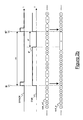
- Figures 2a and 2b schematically show writing and reading operations, respectively, performed by the demapper of Figure 1;
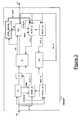
- Figure 3 schematically shows a demapper according to an embodiment of the present invention;
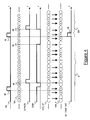
- Figure 4 schematically shows a method of demapping according to an embodiment of the present invention, in a synchronism search state;
- Figure 5 schematically shows the method of demapping according to an embodiment of the present invention, in a transition state;
- Figure 6 schematically shows the method of demapping according to an embodiment of the present invention, in a steady state; and
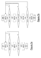
- Figures 7a and 7b schematically shows flow diagrams for passing from a synchronism search state to a steady state and vice versa, respectively, according to embodiments of the present invention.
- Figure 1 schematically shows a demapper according to MI2005A001286, which is adapted to demap a tributary from a higher order frame HF to a lower order frame LF.
- The demapper DEMAP comprises an elastic memory M, for instance a RAM, for storing D words, each word comprising W bits, wherein a bit (typically either the first one or the last one) is the above mentioned alignment bit. Therefore, the overall memory size is DxW, D being the number of rows and W being the number of columns.
- At the input of the memory M, a tributary extraction module TE is provided for extracting the tributary from the higher order frame; such a module TE is adapted to remove from the higher order frame HF the redundancy bits. The module TE then writes into the memory M the tributary words.
- At the input of the memory M an aligner A is further provided, which is cascaded with the module TE. The aligner A is adapted to find the alignment word and to write into the memory M an alignment bit for each memory row, i.e. for each stored tributary word. Thanks to the alignment bit, the tributary can be properly inserted into the lower order frame LF, as it will be shown in greater detail herein after.
- The demapper DEMAP of Figure 1 further comprises a register WCNT_M, whose size is d+dw, wherein d=log2(D) and dw=log2(W). The register WCNT_M is adapted to receive from the module TE a writing synchronization signal SYNCW, and to generate a master writing counter wcnt_m of d+dw bits.
- The demapper DEMAP further comprises a register WCNT_S, whose size is d. The register WCNT_S is adapted to receive the writing synchronization signal SYNCW and a writing enable signal ENW from the module TE. It is further adapted to receive information from the register WCNT_M, as it will be explained herein after. The register WCNT_S is adapted to calculate a slave writing counter wcnt_s of d bits, and to provide the memory M with such a counter as a writing address.
- The module TE, the register WCNT_S and the register WCNT_M are synchronized by the tributary clock tr_cl, which is implicit into the tributary transported by the higher order frame HF.
- At the output of the memory M, a frame generation module FGL is provided for generating the lower order frame, such a module being adapted to read tributary words from the memory M, and to insert them into the lower order frame LF.
- The demapper DEMAP of Figure 1 further comprises a register RCNT_M, whose size is d+dw. The register RCNT_M is adapted to receive from the module FGL a reading synchronization signal SYNCR, and to generate a master reading counter rcnt_m of d+dw bits.
- The demapper DEMAP further comprises a register RCNT_S, whose size is d. The register RCNT_S is adapted to receive the reading synchronization signal SYNCR and a reading enable signal ENR from the module FGL. Further, it is adapted to receive information from the register RCNT_M, as it will be explained in detail herein after. The register RCNT_S is adapted to calculate a slave reading counter rcnt_s of d bits, and to provide the memory M with such a counter as a reading address.
- The register WCNT_M and the register RCNT_M are connected to further modules, which are not described herein after, since they are not relevant to the present description. Such further modules are substantially adapted to perform a clock recovery function according to the values of the master writing counter wcnt_m and of the master reading counter rcnt_m, and they are generically indicated in Figure 1 as CR.
- The recovered clock rec_cl is then used to synchronize the module FGL, the register RCNT_M and the register RCNT_S.
- By referring to Figures 2a and 2b, the operation of the demapper DEMAP of Figure 1 will be now described in detail.
- The demapper DEMAP starts receiving a sequence of higher order frames HF. While the module TE and the aligner A extract redundancy bits and write tributary words into the memory M (each tributary word being associated with a respective alignment bit), at each clock cycle tr_cl the master writing counter wcnt_m is increased by a value so that, in a higher order frame period, the master writing counter wcnt_m counts a number equal to the number of tributary bits comprised in a higher order frame HF. In Figure 2a, mw indicates the number of clock cycles comprised in a higher order frame period. Therefore, if a higher order frame HF comprises mw words, of which yw are redundancy words, the counter wcnt_m, in mw clock cycles, counts (mw-yw)*W bits.
- Similarly, while the module FGL reads tributary words from the memory M and inserts redundancy bits, at each clock cycle rec_cl the master reading counter rcnt_m is increased by a value so that, in a lower order frame period, the master reading counter rcnt_m counts a number equal to the number of tributary bits comprised in a lower order frame LF. In Figure 2b, mr indicates the number of clock cycles comprised in a lower order frame period. Therefore, if a lower order frame LF comprises mr words, of which yr are redundancy words, the counter rcnt_m, in mr clock cycles, counts (mr-yr)*W bits.
- In Figures 2a and 2b, by way of example and not of limitation, it is assumed that mw and mr are both equal to 14, and yw and yr are both equal to 4. Therefore, in 14 clock cycles of the respective clocks tr_cl and rec_cl, both the counter wcnt_m and the counter rcont_m count between 0 and (mw-yw-1)*W=(mr-yr-1)*W=9*W. In Figures 2a and 2b it is further assumed that both mw-yw and mr-yr are equal to D, i.e. to the number of rows in the memory M. Therefore, wcnt_m and rcont_m are periodic with a period equal to mw=mr=14 clock cycles.
- In Figures 2a and 2b, for simplicity, instead of showing the actual values of wcnt_m and rcont_m, the values of the two following counters are shown:
- wcnt_m*=int(wcnt_m/W) and
- rcnt_m*=int(rcnt_m/W),
- Moreover, for simplicity, such values are shown in decimal format, and not in binary format. Therefore, in Figures 2a and 2b, both the counter wcnt_m* and the counter rcnt_m* count between 0 and 9 in 14 clock cycles.
- In the demapper DEMAP of Figure 1, the module TE generates the writing synchronization signal SYNCW (as shown in Figure 2a), while the module FGL generates the reading synchronization signal SYNCR (as shown in Figure 2b). Such signals are periodic and they are high at a single predetermined clock cycle per frame, i.e. every mw and mr clock cycles respectively, as shown in Figures 2a and 2b.
- When the signal SYNCW is high, for instance at a time tA, as shown in Figure 2a, the slave writing counter wcnt_s and the master writing counter wcnt_m are synchronized each other, i.e. their values are set equal. Synchronization preferably comprises the two following operations:
- the dw less significant bits of wcnt_m are set to zero; and
- the d most significant bits of wcnt_m are forced into wcnt_s (as graphically shown in Figure 2a by the vertical arrows).
- Figure 2a for instance shows that at tA the counter wcnt_m has a value so that wcnt_m* is equal to 8. At tA, the dw less significant bits of wcnt_m are set to zero (it must be noticed that this does not change the value of wcnt_m*, which is still equal to 8), and the
value 8 is forced into the slave writing counter wcnt_s. - Similarly, when the signal SYNCR is high, for instance at a time tE, as shown in Figure 2b, the slave reading counter rcnt_s and the master reading counter rcnt_m are synchronized each other, i.e. their values are set equal. Synchronization preferably comprises the two following operations:
- the dw less significant bits of rcnt_m are set to zero; and
- the d most significant bits of rcnt_m are forced into rcnt_s (as graphically shown in Figure 2b by the vertical arrows).
- Figure 2b for instance shows that in tE the counter rcnt_m has a value so that rcnt_m* is equal to 3. In tE, the dw less significant bits of rcnt_m are set to zero (it must be noticed that this does not change the value of rcnt_m*, which is still equal to 3), and the
value 3 is forced into the slave reading counter rcnt_s. - As already mentioned, the module TE is adapted to send to the register WCNT_S a writing enable signal ENW. For instance, such a writing enable signal ENW may be high when tributary words are written into the memory M, while it may be low when redundancy bits are extracted from the higher order frame HF. Figure 2a shows an exemplary writing enable signal ENW. The writing enable signal ENW is high between tA and tB and between tC and tD, while it is low between tB and tC and between tD and tA'. This means that redundancy bits in the higher order frame HF are not consecutive, but they are placed between tB and tC and between tD and tA'. As a whole, they last yw=4 clock cycles.
- Similarly, the module FGL is adapted to send to the register RCNT_S a reading enable signal ENR. For instance, such a reading enable signal ENR may be high when tributary words are read from the memory M, while it may be low when redundancy bits are inserted into the lower order frame LF. Figure 2b shows an exemplary reading enable signal ENR. The reading enable signal ENR is high between tE and tF, while it is low between tF and tE'. This means that redundancy bits in the lower order frame LF are consecutive between tF and tE'. As a whole, they last yr=4 clock cycles.
- According to MI2005A001286, both the slave writing counter wcnt_s and the slave reading counter rcnt_s are increased by one at each clock cycle wherein the respective enable signal ENW and ENR is high.
- Therefore, as shown in Figure 2a, between tA and tB, tributary words are written into memory, so that the signal ENW is high, and therefore the counter wcnt_s is increased by one at each clock cycle. When, at tB, redundancy bits start being extracted from the higher order frame HF, the counter wcnt_s is kept fixed to 2. When, at tC, writing operations restart, the signal ENW is high again, and therefore the counter wcnt_s is increased by one at each clock cycle. When, at tD, redundancy bits start again being extracted from the higher order frame HF, the signal ENW is low again, and the counter wcnt_s is kept fixed to a
value 7. - Similarly, as shown in Figure 2b, between tE and tF, tributary words are read from memory, so that the signal ENR is high, and therefore the counter rcnt_s is increased by one at each clock cycle. When, at tF, redundancy bits start being inserted into the lower order frame LF, the counter rcnt_s is kept fixed to 2.
- Therefore, the two counters wcnt_s and rcnt_s, in mw and mr (i.e. 14) clock cycles respectively, count between 0 and (mw-yw-1)=(mr-yr-1)=9.
- According to MI2005A001286, the slave writing counter wcnt_s is used by the memory M as writing address, while the slave reading counter rcnt_s is used by the memory M as reading address,
- As shown in Figure 2a, after mw (=14) clock cycles, i.e. at tA', the writing synchronization signal SYNCW is high again, so that the master writing counter wcnt_m and the slave writing counter wcnt_s are synchronized each other again, as already seen at tA. Then, the operation of the demapper DEMAP is periodically repeated every mw cycles, as described above between tA and tA'.
- Similarly, as shown in Figure 2b, after mr (=14) clock cycles, i.e. at tE', the reading synchronization signal SYNCR is high again, so that the master reading counter rcnt_m and the slave reading counter rcnt_s are synchronized each other again, as already seen at tE. Then, the operation of the demapper DEMAP is periodically repeated every mr cycles, as described above between tE and tE'.
- Figure 3 schematically shows a demapper DEMAP' according to an embodiment of the present invention, which is capable of recovering lower order synchronism of a sequence of lower order frames LF.
- The demapper DEMAP' according to an embodiment of the present invention comprises an elastic memory M, for instance a RAM, for storing D words, each word comprising W bits, wherein a bit (typically either the first one or the last one) is the above mentioned alignment bit. Therefore, the overall memory size is DxW, D being the number of rows and W being the number of columns.
- At the input of the memory M, a tributary extraction module TE is provided for extracting the tributary from the lower order frame; such a module TE is adapted to remove from the higher order frame HF the redundancy bits. The module TE then writes into the memory M the tributary words.
- At the input of the memory M an aligner A is further provided, which is cascaded with the module TE. The aligner A is adapted to find the alignment word and to write into the memory M an alignment bit for each memory row, i.e. for each stored tributary word. Thanks to the alignment bit, the tributary can be properly inserted into the lower order frame LF, as it will be shown in greater detail herein after.
- The demapper DEMAP' of Figure 3 further comprises a register WCNT_M, whose size is d+dw. The register WCNT_M is adapted to receive from the module TE a writing synchronization signal SYNCW, and to generate a master writing counter wcnt_m of d+dw bits.
- The demapper DEMAP' further comprises a register WCNT_S, whose size is d. The register WCNT_S is adapted to receive the writing synchronization signal SYNCW and a writing enable signal ENW from the module TE. It is further adapted to receive information from the register WCNT_M, as it will be explained herein after. The register WCNT_S is adapted to calculate a slave writing counter wcnt_s of d bits, and to provide the memory M with such a counter as a writing address.
- The module TE, the register WCNT_S and the register WCNT_M are synchronized by the tributary clock tr_cl, which is implicit into the tributary transported by the higher order frame HF.
- At the output of the memory M, a frame generation module FGL is provided for generating the lower order frame, such a module being adapted to read tributary words from the memory M, and to insert them into the lower order frame LF.
- The demapper DEMAP' of Figure 3 further comprises a register RCNT_M, whose size is d+dw. The register RCNT_M is adapted to receive from the module FGL a reading synchronization signal SYNCR, and to generate a master reading counter rcnt_m of d+dw bits.
- The demapper DEMAP further comprises a register RCNT_S, whose size is d. The register RCNT_S is adapted to receive the reading synchronization signal SYNCR and a reading enable signal ENR from the module FGL. Further, it is adapted to receive information from the register RCNT_M, as it will be explained in detail herein after. The register RCNT_S is adapted to calculate a slave reading counter rcnt_s of d bits, and to provide the memory M with such a counter as a reading address.
- The register WCNT_M and the register RCNT_M are connected to further modules, which are not described herein after, since they do not fall within the scope of the present invention. Such further modules are substantially adapted to perform a clock recovery function according to the values of the master writing counter wcnt_m and of the master reading counter rcnt_m, and they are indicated in Figure 1 as CR.
- The recovered clock rec_cl is then used to synchronize the module FGL, the register RCNT_M and the register RCNT_S.
- According to the embodiment of the present invention shown in Figure 3, the demapper DEMAP' further comprises a state control module CTRL_STATE. Such a state control module CTRL_STATE is adapted to read, for each tributary word which is written into the memory, the alignment bit, to process it, and to forward to the register RCNT_S a change state signal ch_state according to the results of said processing, as it will be shown in further details herein after.
- By referring to Figures 4, 5, 6, the operation of the demapper DEMAP' according to an embodiment of the present invention will now be described in detail.
- As the writing operation of the demapper DEMAP' is substantially analogous to the writing operation of the demapper DEMAP of Figure 1, a detailed description will be omitted.
- It is only reminded that, while writing tributary words into the memory M, the aligner A writes, for each tributary word written into the memory, a respective alignment bit, which may be equal to 1 for the alignment word, while is equal to 0 for the remaining words. In the following description and in the Figures, the sequence of alignment bits read from memory by the modules FGL and CTRL_STATE will be termed "Ab". Under the above assumptions, such a signal alignment bit Ab read from memory is high while reading the alignment word from memory, and it is low while reading any other tributary word from memory.
- Moreover, as it is assumed that a lower order frame LF comprises mr=14 words, among which yr=4 words are redundancy words. It is also assumed that the number D of memory rows is equal to the number mr-yr=10 of tributary words in a lower order frame LF; therefore, the alignment word is always stored at a same memory row (unless loss either of higher order synchronism or of lower order synchronism during writing operations). For instance, in Figures 4, 5 and 6, it is assumed that writing operations are synchronized, so that the alignment word is always stored at a memory row pointed by the
memory address 4. Therefore, each time the reading address equals 4, the alignment word is read from memory, and consequently the alignment bit Ab read from memory is high. - Moreover, in the demapper DEMAP', similarly to the demapper DEMAP of Figure 1, the slave reading counter rcnt_s is used by the memory M as reading address.
- Moreover, in the demapper DEMAP', similarly to the demapper DEMAP of Figure 1, the master reading counter rcnt_m is increased at each clock cycle by a value so that, in mr clock cycles, the counter rcnt_m counts (mr-yr)*W bits.
- According to the present invention, when the demapper DEMAP' starts receiving a new sequence of higher order frames HF, the module CTRL_STATE forces the demapper DEMAP' in a first state, which will be termed "synchronization search state" or briefly "state B". In such a state B, the demapper DEMAP' starts searching the lower order synchronism.
- According to the present invention, when the demapper DEMAP' is in the state B, the slave reading counter rcnt_s is synchronized to the master reading counter rcnt_m at each clock cycle, independently of the signal ENR value and of the signal SYNCR value. Therefore, during state B, the slave reading counter rcnt_s (i.e. the reading address), which is shown in Figure 4, evolves according to the following equation: rcnt_s=rcnt_m*=int(rcnt_m/W).
- It can be noticed that, according to the present invention, while searching lower order synchronism (i.e. during state B), both the signal ENR and the signal SYNCR are ignored. Indeed, the slave reading counter rcnt_s is increased at each clock cycle, and it is never kept fixed, as explained above by referring to Figure 2b.
- Moreover, according to the present invention, when the module FGL starts reading from the memory M, it starts increasing a time base counter tbc. Such a time base counter tbc is increased by one at each clock cycle rec_cl, and it is adapted to count between 0 and mr-1 (i.e. 13). Therefore, if the time base counter tbc were free-running, it would be periodic with a period equal to mr.
- The time base counter tbc, according to the present invention, is the counter according to which the module FGL generates the lower order frame LF. For instance, time base counter values between 0 and mr-yr-1 (i.e. 9) induce the signal ENR to be high, so that tributary words are read from memory. On the other hand, time base counter values between mr-yr (i.e. 10) and mr-1 (i.e. 13) induce the signal ENR to be low, so that redundancy bits are inserted into the lower order frame LF.
- Moreover, according to the present invention, the time base counter tbc manages the reading synchronization signal SYNCR. For instance, when the time base counter tbc is equal to zero, the signal SYNCR is high, while for all the other tbc counter values (i.e. between 1 and mr-1=13), the signal SYNCR is low.
- According to the present invention, when the module FGL reads a tributary word from memory, it also reads the associated alignment bit Ab, which is high while the alignment word is read from memory.
- For instance, by referring to Figure 4, at t0 the alignment bit Ab read from memory is high. In t0, the slave reading counter rcnt_s, which indicates the reading address, is equal to 4.
- According to the present invention, the time base counter tbc is free-running as long as the alignment bit Ab read from memory is low. When, during state B, the alignment bit Ab read from memory becomes high for the first time, during the next clock cycle the time base counter tbc is forced to a predefined value, which is preferably equal to mr-1 (i.e. 13). The time base counter tbc then restarts counting from 13, thus making the signals ENR and SYNCR evolve accordingly. As already mentioned, in state B the slave reading counter and the master reading counter evolve independently of the values of SYNCR and ENR, which change at the instants t1, t2 and t5. Therefore, according to the present invention, during the synchronism search state B, the slave reading counter rcnt_s evolves continuously, without showing discontinuities, as it is synchronized to the master reading counter rcnt_m at each clock cycle, and not only when the signal SYNCR is high. On the contrary, if synchronization were performed only when SYNCR is high, discontinuities could appear, as shown in Figure 2b wherein, upon synchronization in tE, the value of the slave reading counter rcnt_s passes from 7 to 3.
- In t3, the master reading counter rcnt_m is equal again to a value such that the slave reading counter rcnt_s is equal to 4. Therefore, the module FGL reads again at the memory row pointed by the
reading address 4, wherein the alignment word is stored. Therefore, the alignment bit Ab read from memory is high. If the demapper DEMAP' is properly working, the instant t3 is spaced from t0 by mr (i.e. 14) clock cycles. This is due to the fact that the master reading counter rcnt_m, and therefore the synchronized slave reading counter rcnt_s, in mr clock cycles counts exactly mr-yr, i.e. it goes through the whole memory M and then it points again to the memory row pointed in t0. - According to the present invention, as mentioned above, during the clock cycle next to t3 the time base counter tbc is again forced to the predefined value mr-1.
- Further, according to the present invention, the state control module CTRL_STATE generates a synchronism check signal SY_FAW_INT. During the synchronism search state B, such a synchronism check signal SY_FAW_INT is low, and becomes high only during the clock cycle wherein the time base counter tbc is equal to mr-2 (i.e. 12). This value mr-2 is chosen as it is the value assumed by the time base counter tbc while reading the alignment word from memory.
- According to the present invention, the state control module CTRL_STATE checks the value of the signal SY FAW_INT while the alignment word is read from memory, i.e. while the alignment bit Ab read from memory is high. If also the signal SY_FAW_INT is high during such a clock cycle, at t4 the state control module CTRL_STATE forces the demapper DEMAP' to change state, thus passing from the synchronism search state B to a transition state B1.
- The operation of the demapper DEMAP' during the transition state B1 in shown in Figure 5.
- During the transition state B1, as during the synchronism search state B, the master reading counter rcnt_m and the slave reading counter rcnt_s still evolve in a continuous, synchronized way. When, at t7, the alignment word is read again from memory, i.e. the synchronization bit read from memory Ab is high again, the time base counter tbc is forced to mr-1=13 again. The signals SYNCR and ENR evolve according to the time base counter tbc. However, as in state B, the evolution of such signals SYNCR and ENR does not affect the slave reading counter rcnt_s, which is synchronized to the master reading counter rcnt_m at each clock cycle.
- Moreover, as at t7 the time base counter tbc is equal to mr-2=12, the signal SY_FAW_INT is forced to be high. As in state B, the state control module CTRL_STATE checks the value of SY_FAW_INT while the alignment word is read from memory. If the value of the signal SY FAW_INT is high, the module CTRL_STATE forces the demapper DEMAP' to change state, i.e. to pass from the transition state B to a steady state A. Otherwise, the module CTRL_STATE forces the demapper DEMAP' to go back to the synchronization search state B; this latter case will be schematically shown herein after by referring to Figure 7a.
- It can be noticed that the state control module CTRL_STATE checks twice the SY_FAW_INT value. The first check, at t3, allows the demapper to pass from the synchronization search state B, which is the initial state of the demapper DEMAP', to the transition state B1, wherein the demapper operation is substantially identical to the demapper operation in state B. The second check, at t7, allows the demapper DEMAP' to pass from the transition state B1 to a steady state A, which will be described herein after by referring to Figure 6.
- According to other embodiments of the present invention, which are not shown in the drawings, the transition state B1 may be avoided, thus passing directly, after the first check at t3, from the synchronization search state B to the steady state A. However, the embodiment shown in Figure 5 with the transition state B1 is preferred, since it advantageously allows to have a double confirmation that lower order synchronism has been recovered. In other words, it advantageously allows to have a double confirmation that reading operation is performed so that the alignment words of successive low order frames are always placed at a predetermined position of the lower order frames, i.e. they are spaced by mr clock cycles. This assures that low order frames are properly generated (proper number of redundancy bits, redundancy bits inserted in proper positions, etc.).
- It also remarked that the operation of the demapper DEMAP' during state B and state B1 is substantially identical. Therefore, for passing from state B to state B1 or vice versa, the state control module CTRL_STATE does not have to send any change control signal to any module of the demapper DEMAP'. Indeed, changing from state B to state B1 simply requires to store the result of checking the SY-FAW_INT value at t3, so that, at the next check at t7, the state control module CTRL_STATE will be able to determine whether to go back to state B or to pass to state A, as it will be shown in further detail by referring to Figure 7a and 7b.
- Figure 6 shows the operation of the demapper DEMAP' during the steady state A, according to the present invention.
- At t8, after the check performed at t7, the state control module CTRL_STATE, for forcing the demapper DEMAP' to pass to the steady state A, send a change state command ch_state to the slave reading register RCNT_S. Upon reception of such a command, the slave reading register RCNT_S starts operating as shown in Figure 2b. Therefore, during the steady state A, the slave reading counter rcnt_s is synchronized to the master reading counter rcnt_m only when the reading synchronization signal SYNCR is high. Moreover, the slave reading counter rcnt_s is increased by one at each clock cycle wherein the reading enable signal ENR is high; otherwise, the slave reading counter rcnt_s is kept fixed to a constant value.
- More particularly, by referring to Figure 6, when at t9 the time base counter tbc is equal to 0, the signal SYNCR is high, and therefore the slave reading counter rcnt_s is synchronized to the master reading counter rcnt_m. In the following cycles, the slave reading counter rcnt_s is increased by one at each clock cycle, until, after mr-yr clock cycles, i.e. at t10, it is still equal to 4, as in t7. Therefore, as the reading address corresponds to the memory row wherein the alignment word is stored, the alignment bit Ab read from memory is high.
- It is remarked that t7 and t10 (i.e. two clock cycles wherein alignment words of two successive low order frames are read from memory) are separated by mr-yr clock cycles (in Figure 6, it can be noticed that the time base counter tbc varies from 12 to 9 between t7 and t10).
- According to the present invention, during the steady state A, the time base counter tbc is free-running. Therefore, it evolves independently of the alignment bit Ab read from memory. Therefore, the time base counter tbc will evolve until, at t11, it is equal to 10, thus forcing the reading enable signal ENR to be low. Consequently, the slave reading counter rcnt_s is kept fixed from t11 to t12. At t12, the time base counter tbc is equal to 0, thus forcing the reading enable signal ENR to be high.
- Further, at t12, as the time base counter is equal to 0, the reading synchronization signal SYNC is forced to be high, thus forcing the slave reading counter rcnt_s to be synchronized to the master reading counter rcnt_m.
- Starting from t10, i.e. starting from the first time the alignment word is read from memory during the steady state A, the operation of the demapper DEMAP' periodically repeats every mr clock cycles. Figure 6 only shows t13 and t14. At 13, occurring mr clock cycles after t10, the alignment word is once again read from memory. At t14, occurring mr clock cycles after t11, the time base counter tbc is equal to 10, thus forcing the signal ENR to be low, and thus forcing the slave reading counter to be fixed to a constant value.
- Preferably, according to the present invention, during the steady state A, for each lower order frame a check is performed for verifying that the demapper is still properly working, i.e. the recovered lower order synchronism has not been lost.
- According to the present invention, as shown in Figure 6, during state A the state control module CTRL_STATE still generates the signal SY_FAW_INT. However, during state A, the signal SY_FAW_INT is forced to be high only when the time base counter tbc is equal to mr-yr-1=9. Then, the state control module CTRL_STATE checks the value of the signal SY_FAW_INT while the alignment word is read from memory, i.e. the alignment bit Ab read from memory is high. If the value of the signal SY_FAW_INT during such a clock cycle is high, the state control module CTRL_STATE determines that the recovered lower order synchronism has not been lost, and the demapper is still properly working.
- The state control module CTRL_STATE repeats such a check for each lower order frame. Until the result of this check is positive, the demapper DEMAP' is kept in the steady state A.
- However, according to the present invention, if the demapper DEMAP' looses the lower order synchronism (for instance, due to a writing error the alignment word is no more stored at the memory row pointed by the reading address 4), the state control module CTRL_STATE determines that the SY_FAW_INT value while reading the alignment word is not high. This is due to the fact that the alignment word is now read during a clock cycle which becomes different from the clock cycle wherein the time base counter tbc is equal to mr-yr-1 =9.
- In such a case, according to the present invention, the state control module CTRL_STATE may for instance force the demapper DEMAP' to go back directly to the synchronism search state B after a single check of the SY_FAW_INT value. Alternatively, the state control module CTRL_STATE could perform more than one check on the SY_FAW_INT value before determining that lower order synchronism has been lost and consequently that the demapper DEMAP' must be forced back to the synchronism search state B, as it will be shown herein after by referring to Figures 7a and 7b.
- Figure 7a shows a flow diagram for passing from the synchronism search state B to the steady state A according to an embodiment of the present invention.
- According to such an embodiment, when the demapper DEMAP' starts receiving a new higher order frame sequence to be demapped, the demapper DEMAP' is in its synchronism search state B. The demapper DEMAP' is in its synchronism search state B also when, while receiving a higher order frame sequence, lower order synchronism is lost. After entering such a state B, for each lower order frame, the value of the signal SY_FAW_INT is checked at each clock cycle wherein an alignment word is read from memory (i.e. the alignment bit Ab read from memory is high). In other words, each time an alignment word is read from memory, it is checked whether Ab=SY_FAW_INT.
- In the negative, it is determined that synchronism has not been recovered yet, and the demapper DEMAP' remains in its synchronism search state B.
- The first time the check Ab=SY_FAW_INT is in the affirmative, the demapper DEMAP', according to such an embodiment, passes from state B to the above described transition state B1.
- While in state B1, for the first lower order frame generated during state B1, it is checked whether Ab=SY_FAW_INT at the clock cycle wherein the alignment word is read from memory. In the negative, the demapper DEMAP' goes back to the synchronization search state B. Otherwise, the demapper DEMAP' passes to the steady state A.
- Therefore, in the embodiment shown in Figure 7a, changing from the synchronism search state B to the steady state B1 requires two steps. In other words, the equation Ab=SY FAW_INT must be true for two consecutive lower order frames. This advantageously allows to have a double confirmation of having recovered lower order synchronism before passing to state A. According to other embodiments of the present invention, not shown in the drawings, the transition state B1 could be avoided. In this case, determining that Ab=SY_FAW_INT for a single lower order frame allows to change from state B to state A. According to other embodiments not shown in the drawings, more than one transition state could be provided between state B and state A.
- Figure 7b shows a flow diagram for passing from the steady state A to the synchronism search state B according to an embodiment of the present invention.
- According to such a embodiment, when the demapper is properly working (i.e. it is properly generating lower order frames, as the recovered synchronism is maintained), the demapper is in its steady state A. During state A, for each lower order frame, the value of the signal SY_FAW_INT is checked at each clock cycle wherein an alignment word is read from memory (i.e. the alignment bit Ab read from memory is high). In other words, each time an alignment word is read from memory, it is checked whether Ab=SY_FAW_INT.
- While in the affirmative, it is determined that the demapper DEMAP' is properly working and the lower order synchronism has not been lost, so that the demapper DEMAP' remains in its steady state A.
- The first time the check Ab=SY_FAW_INT is in the negative, the demapper DEMAP', according to such an embodiment, passes from state A to a first transition state A1, as shown in Figure 7b.
- During the first transition state A1, the demapper DEMAP' still operates as in steady state A. However, the negative result of the check is stored (i.e. the demapper stores the information that lower order synchronism has been lost for a lower order frame). During state A1, it is again checked, for the first lower order frame generated during state A1, whether Ab=SY_FAW_INT at the clock cycle wherein the alignment word is read from memory. In the affirmative, the demapper DEMAP' goes back to the steady state B, as it is determined that synchronism has been lost for a single lower order frame, and therefore it is not necessary to go back to the synchronism search state B. Otherwise (Ab different from SY_FAW_INT while reading the alignment word from memory), the demapper DEMAP' passes to a second transition state A2.
- During the second transition state A2, the demapper DEMAP' still operates as in steady state A. However, the negative results of the checks are stored (i.e. the demapper stores the information that lower order synchronism has been lost for two consecutive lower order frames). During state A2, it is again checked, for the first lower order frame generated during state A2, whether Ab=SY_FAW_INT at the clock cycle wherein the alignment word is read from memory. In the affirmative, the demapper DEMAP' goes back to the steady state A, as it is determined that synchronism has been lost only for a two consecutive lower order frames, and therefore it is not necessary to go back to the synchronism search state B. Otherwise (Ab different from SY_FAW_INT while reading the alignment word from memory), the demapper DEMAP' passes to the synchronism search state B.
- Therefore, in the embodiment shown in Figure 7b, changing from the synchronism search state B to the steady state A requires three steps, i.e. the equation Ab=SY_FAW_INT must be true for three consecutive lower order frames. This advantageously allows to have a triple confirmation of having lost the lower order synchronism before passing to the synchronism search state B. According to other embodiments of the present invention, not shown in the drawings, the transition states A1 and A2 could be avoided. In this case, determining that Ab is different from SY_FAW_INT for a single lower order frame allows to change from state A to state B. Similarly, only a single transition state from A to B could be provided, or any number of transition states higher that two.
- Transition states advantageously allow to reduce unnecessary changes between state A and state B, that would imply unnecessary changes of the demapper operations (and in particular of its slave reading register RCNT_M).
- Therefore, the present invention advantageously allows to demap a tributary from a higher order frame to a lower order frame by recovering lower order synchronism in a particularly efficient way. In fact, according to the present invention, while synchronism is searched in state B, the slave reading counter, which is indicative of the reading address, varies continuously, so that the alignment word is always read at the same lower order frame position.
Claims (16)
- A method of demapping a tributary from a first frame (HF) into a second frame (LF), said first frame (HF) comprising a plurality of tributary words and a synchronization word for synchronizing said second frame (LF), the method comprising:- providing a first counter (rcnt_m) and a second counter (rcnt_s);- increasing said first counter (rcnt_m) by a first value at each clock cycle of said second frame (LF);- performing reading operations according to said second counter (rcnt_s);characterized in that it further comprises:- generating synchronization information (tbc, SY_FAW_INT) according to said synchronization word;- according to said synchronization information (tbc, SY_FAW_INT), performing a change of state between a first state (B) and a second state (A), wherein, in said first state (B), said second counter (rcnt_s) is synchronized to said first counter (rcnt_m) at each clock cycle of said second frame (LF), and in said second state (A), said second counter (rcnt_s) is synchronized to said first counter (rcnt_m) at a predetermined instant (SYNCR) of said second frame (LF) and said second counter (rcnt_s) is increased by a second value at each clock cycle of said second frame (LF) wherein said reading operation is performed.
- The method according to claim 1, characterized in that said step of performing a change of state further comprises, in case of changing from the first state (B) to the second state (A), passing through a first number of transition states (B1), said first number being equal to or higher than 1.
- The method according to claim 2, characterized in that in each of said first number of transition states (B1), said second counter (rcnt_s) is synchronized to said first counter (rcnt_m) at each clock cycle of said second frame (LF).
- The method according to any of claims 1 to 3, characterized in that said step of changing state between the first state (B) and the second state (A) comprises, in case of changing from the second state (A) to the first state (B), passing through a second number of transition states (A1, A2), said second number being equal to or higher than 1.
- The method according to claim 4, characterized in that in each of said second number of transition states (A1, A2), said second counter (rcnt_s) is synchronized to said first counter (rcnt_m) at a predetermined instant (SYNCR) of said second frame (LF) and said second counter (rcnt_s) is increased by a second value at each clock cycle of said second frame (LF) wherein said reading operation is performed.
- The method according to any of claims 1 to 5, characterized in that said generating synchronization information comprises generating a third counter (tbc).
- The method according to claim 6, characterized in that, in said first state (B), said third counter (tbc) is increased by one at each clock cycle of said second frame (LF), and it is forced to a first predefined value (mr-1) at each clock cycle wherein said synchronization word is read.
- The method according to claim 6 or 7, characterized in that, in said second state (A), said third counter (tbc) is increased by one at each clock cycle of said second frame (LF).
- The method according to any of claims 6 to 8, characterized in that said generating synchronization information comprises generating a signal (SY_FAW_INT), which is adapted to switch between two different logic values.
- The method according to claim 9, characterized in that, in said first state (B), the logic value of said signal (SY_FAW_INT) is switched when said third counter (tbc) is equal to a second predefined value (mr-2).
- The method according to claim 9 or 10, characterized in that, in said second state (A), the logic value of said signal (SY_FAW_INT) is switched when said third counter (tbc) is equal to a third predefined value (mr-yr-1).
- The method according to any of claims 9 to 11, characterized in that said generating synchronization information comprises checking the value of said signal (SY_FAW_INT) at each clock cycle wherein said synchronization word is read.
- A demapper (DEMAP') for demapping tributary from a first frame (HF) into a second frame (LF), said first frame (HF) comprising a plurality of tributary words and a synchronization word for synchronizing said second frame (LF), the demapper comprising:- a first register (RCNT_M) for generating a first counter (rcnt_m) which is adapted to be increased by a first value at each clock cycle of said second frame (LF);- a second register (RCNT_S) for generating a second counter (rcnt_s) which is adapted to manage reading operations;characterized in that it further comprises:- a state control module (CTRL_STATE) for:- generating synchronization information (tbc, SY_FAW_INT) according to said synchronization word; and- according to said synchronization information (tbc, SY_FAW_INT), performing a change of state between a first state (B) and a second state (A), wherein, in said first state (B), said second counter (rcnt_s) is synchronized to said first counter (rcnt_m) at each clock cycle of said second frame (LF), and in said second state (A), said second counter (rcnt_s) is synchronized to said first counter (rcnt_m) at a predetermined instant (SYNCR) of said second frame (LF) and said second counter (rcnt_s) is increased by a second value at each clock cycle of said second frame (LF) wherein said reading operation is performed.
- The demapper according to claim 13, characterized in that said state control module (CTRL_STATE), in case of changing from the first state (B) to the second state (A), performs the change of state passing through a first number of transition states (B1), said first number being equal to or higher than 1.
- The demapper according to claim 13 or 14, characterized in that, said state control module (CTRL_STATE), in case of changing from the second state (A) to the first state (B), performs the change of state passing through a second number of transition states (A1, A2), said second number being equal to or higher than 1
- A network node of a telecommunication network, characterized in that it comprises a demapper according to any of claims 13 to 15.
Priority Applications (4)
| Application Number | Priority Date | Filing Date | Title |
|---|---|---|---|
| AT05292695T ATE519286T1 (en) | 2005-12-14 | 2005-12-14 | METHOD AND APPARATUS FOR RE-IMAGING A SUBSYSTEM UNIT AND FOR RECOVERING THE SYNCHRONISM OF THE LOWER SUBSYSTEM UNIT |
| EP05292695A EP1798882B1 (en) | 2005-12-14 | 2005-12-14 | Method and device for demapping a tributary and recovering the lower order tributary synchronism |
| US11/610,515 US8165174B2 (en) | 2005-12-14 | 2006-12-14 | Method and device for demapping a tributary recovering lower order synchronism |
| CN2006100643745A CN101039174B (en) | 2005-12-14 | 2006-12-14 | Method and device for demapping a tributary recovering lower order synchronism |
Applications Claiming Priority (1)
| Application Number | Priority Date | Filing Date | Title |
|---|---|---|---|
| EP05292695A EP1798882B1 (en) | 2005-12-14 | 2005-12-14 | Method and device for demapping a tributary and recovering the lower order tributary synchronism |
Publications (2)
| Publication Number | Publication Date |
|---|---|
| EP1798882A1 true EP1798882A1 (en) | 2007-06-20 |
| EP1798882B1 EP1798882B1 (en) | 2011-08-03 |
Family
ID=36097223
Family Applications (1)
| Application Number | Title | Priority Date | Filing Date |
|---|---|---|---|
| EP05292695A Expired - Lifetime EP1798882B1 (en) | 2005-12-14 | 2005-12-14 | Method and device for demapping a tributary and recovering the lower order tributary synchronism |
Country Status (4)
| Country | Link |
|---|---|
| US (1) | US8165174B2 (en) |
| EP (1) | EP1798882B1 (en) |
| CN (1) | CN101039174B (en) |
| AT (1) | ATE519286T1 (en) |
Citations (1)
| Publication number | Priority date | Publication date | Assignee | Title |
|---|---|---|---|---|
| WO2002098087A1 (en) | 2001-05-25 | 2002-12-05 | Transwitch Corporation | Method and apparatus for desynchronizing a ds-3 signal and/or an e3 signal from the data portion of an sts/stm payload |
Family Cites Families (5)
| Publication number | Priority date | Publication date | Assignee | Title |
|---|---|---|---|---|
| JP2874889B2 (en) * | 1989-04-14 | 1999-03-24 | 株式会社日立製作所 | Frame phase synchronization method by pointer conversion and its circuit |
| DE4108429A1 (en) * | 1991-03-15 | 1992-09-17 | Philips Patentverwaltung | TRANSMISSION SYSTEM FOR THE DIGITAL SYNCHRONOUS HIERARCHY |
| EP0702465A1 (en) * | 1994-09-13 | 1996-03-20 | T.R.T. Telecommunications Radioelectriques Et Telephoniques | Transmission system and device for multiplexing-demultiplexing a binary data stream that might be justified |
| DE60206468T2 (en) * | 2002-02-28 | 2006-05-11 | Alcatel | Plesiochroner demultiplexer |
| US7593430B2 (en) * | 2005-07-28 | 2009-09-22 | Alcatel-Lucent Usa Inc. | Method and apparatus for generating virtual clock signals |
-
2005
- 2005-12-14 AT AT05292695T patent/ATE519286T1/en not_active IP Right Cessation
- 2005-12-14 EP EP05292695A patent/EP1798882B1/en not_active Expired - Lifetime
-
2006
- 2006-12-14 US US11/610,515 patent/US8165174B2/en not_active Expired - Fee Related
- 2006-12-14 CN CN2006100643745A patent/CN101039174B/en not_active Expired - Fee Related
Patent Citations (1)
| Publication number | Priority date | Publication date | Assignee | Title |
|---|---|---|---|---|
| WO2002098087A1 (en) | 2001-05-25 | 2002-12-05 | Transwitch Corporation | Method and apparatus for desynchronizing a ds-3 signal and/or an e3 signal from the data portion of an sts/stm payload |
Also Published As
| Publication number | Publication date |
|---|---|
| US20070133613A1 (en) | 2007-06-14 |
| CN101039174B (en) | 2012-10-31 |
| US8165174B2 (en) | 2012-04-24 |
| CN101039174A (en) | 2007-09-19 |
| ATE519286T1 (en) | 2011-08-15 |
| EP1798882B1 (en) | 2011-08-03 |
Similar Documents
| Publication | Publication Date | Title |
|---|---|---|
| JP2747077B2 (en) | Frame synchronization circuit | |
| JPH084255B2 (en) | Frame reconstruction interface for digital bitstreams multiplexed by time division multiplexed digital dependent stations at different bit rates. | |
| EP0447461A4 (en) | Virtual tributary cross connect switch and switch network utilizing the same | |
| US5265090A (en) | Switching element for cross-connect equipment for digital bit streams multiplexed by time-division multiplexing digital tributaries with different bit rates | |
| US5202904A (en) | Pulse stuffing apparatus and method | |
| JPH0537483A (en) | Tu-3 pointer exchange processing system | |
| EP1798882B1 (en) | Method and device for demapping a tributary and recovering the lower order tributary synchronism | |
| US6654368B1 (en) | Apparatus and method for processing frame structured data signals | |
| EP1742399A1 (en) | Method and device for mapping/demapping a trinutary signal into/from a synchronus frame | |
| CN101072090B (en) | Method and device for extended super frame synchronization for T1 system | |
| JP2616408B2 (en) | Pointer replacement circuit | |
| JP3034561B2 (en) | Frame phase synchronization circuit | |
| JP4441648B2 (en) | Frame synchronization circuit | |
| JP3441890B2 (en) | Overhead termination / pointer processing apparatus and overhead termination processing apparatus in SDH transmission system | |
| JP3010634B2 (en) | Frame synchronous multiplex processing | |
| JP2960761B2 (en) | Elastic buffer for TDMA signal | |
| JP2876747B2 (en) | Frame synchronization circuit | |
| JPH09294116A (en) | Speed conversion circuit | |
| JPH0736547B2 (en) | Word interleaved multiplex signal separation device | |
| Calazans et al. | Design, Validation and Prototyping of the EMS SDH STM-1 Mapper Soft-core | |
| JPH07212338A (en) | Pointer processing circuit | |
| JPH08298492A (en) | Multi-frame synchronization circuit | |
| JP2004254214A (en) | Phase adjustment circuit in time switch | |
| JPH11187006A (en) | Pcm digital communication equipment | |
| US20030043858A1 (en) | Device for processing data signals, method thereof, and device for multiplexing data signals |
Legal Events
| Date | Code | Title | Description |
|---|---|---|---|
| PUAI | Public reference made under article 153(3) epc to a published international application that has entered the european phase |
Free format text: ORIGINAL CODE: 0009012 |
|
| AK | Designated contracting states |
Kind code of ref document: A1 Designated state(s): AT BE BG CH CY CZ DE DK EE ES FI FR GB GR HU IE IS IT LI LT LU LV MC NL PL PT RO SE SI SK TR |
|
| AX | Request for extension of the european patent |
Extension state: AL BA HR MK YU |
|
| RIN1 | Information on inventor provided before grant (corrected) |
Inventor name: RINALDI, SONIA Inventor name: RAZZETTI, LUCA GABRIELE Inventor name: SORGE, PAOLO |
|
| AKX | Designation fees paid |
Designated state(s): AT BE BG CH CY CZ DE DK EE ES FI FR GB GR HU IE IS IT LI LT LU LV MC NL PL PT RO SE SI SK TR |
|
| 17P | Request for examination filed |
Effective date: 20071210 |
|
| 17Q | First examination report despatched |
Effective date: 20080325 |
|
| GRAP | Despatch of communication of intention to grant a patent |
Free format text: ORIGINAL CODE: EPIDOSNIGR1 |
|
| GRAS | Grant fee paid |
Free format text: ORIGINAL CODE: EPIDOSNIGR3 |
|
| GRAA | (expected) grant |
Free format text: ORIGINAL CODE: 0009210 |
|
| AK | Designated contracting states |
Kind code of ref document: B1 Designated state(s): AT BE BG CH CY CZ DE DK EE ES FI FR GB GR HU IE IS IT LI LT LU LV MC NL PL PT RO SE SI SK TR |
|
| REG | Reference to a national code |
Ref country code: GB Ref legal event code: FG4D |
|
| REG | Reference to a national code |
Ref country code: CH Ref legal event code: EP |
|
| REG | Reference to a national code |
Ref country code: IE Ref legal event code: FG4D |
|
| REG | Reference to a national code |
Ref country code: DE Ref legal event code: R096 Ref document number: 602005029296 Country of ref document: DE Effective date: 20110929 |
|
| REG | Reference to a national code |
Ref country code: NL Ref legal event code: VDEP Effective date: 20110803 |
|
| LTIE | Lt: invalidation of european patent or patent extension |
Effective date: 20110803 |
|
| PG25 | Lapsed in a contracting state [announced via postgrant information from national office to epo] |
Ref country code: IS Free format text: LAPSE BECAUSE OF FAILURE TO SUBMIT A TRANSLATION OF THE DESCRIPTION OR TO PAY THE FEE WITHIN THE PRESCRIBED TIME-LIMIT Effective date: 20111203 Ref country code: FI Free format text: LAPSE BECAUSE OF FAILURE TO SUBMIT A TRANSLATION OF THE DESCRIPTION OR TO PAY THE FEE WITHIN THE PRESCRIBED TIME-LIMIT Effective date: 20110803 Ref country code: PT Free format text: LAPSE BECAUSE OF FAILURE TO SUBMIT A TRANSLATION OF THE DESCRIPTION OR TO PAY THE FEE WITHIN THE PRESCRIBED TIME-LIMIT Effective date: 20111205 Ref country code: LT Free format text: LAPSE BECAUSE OF FAILURE TO SUBMIT A TRANSLATION OF THE DESCRIPTION OR TO PAY THE FEE WITHIN THE PRESCRIBED TIME-LIMIT Effective date: 20110803 Ref country code: NL Free format text: LAPSE BECAUSE OF FAILURE TO SUBMIT A TRANSLATION OF THE DESCRIPTION OR TO PAY THE FEE WITHIN THE PRESCRIBED TIME-LIMIT Effective date: 20110803 Ref country code: SE Free format text: LAPSE BECAUSE OF FAILURE TO SUBMIT A TRANSLATION OF THE DESCRIPTION OR TO PAY THE FEE WITHIN THE PRESCRIBED TIME-LIMIT Effective date: 20110803 |
|
| REG | Reference to a national code |
Ref country code: AT Ref legal event code: MK05 Ref document number: 519286 Country of ref document: AT Kind code of ref document: T Effective date: 20110803 |
|
| RAP2 | Party data changed (patent owner data changed or rights of a patent transferred) |
Owner name: ALCATEL LUCENT |
|
| PG25 | Lapsed in a contracting state [announced via postgrant information from national office to epo] |
Ref country code: GR Free format text: LAPSE BECAUSE OF FAILURE TO SUBMIT A TRANSLATION OF THE DESCRIPTION OR TO PAY THE FEE WITHIN THE PRESCRIBED TIME-LIMIT Effective date: 20111104 Ref country code: AT Free format text: LAPSE BECAUSE OF FAILURE TO SUBMIT A TRANSLATION OF THE DESCRIPTION OR TO PAY THE FEE WITHIN THE PRESCRIBED TIME-LIMIT Effective date: 20110803 Ref country code: PL Free format text: LAPSE BECAUSE OF FAILURE TO SUBMIT A TRANSLATION OF THE DESCRIPTION OR TO PAY THE FEE WITHIN THE PRESCRIBED TIME-LIMIT Effective date: 20110803 Ref country code: LV Free format text: LAPSE BECAUSE OF FAILURE TO SUBMIT A TRANSLATION OF THE DESCRIPTION OR TO PAY THE FEE WITHIN THE PRESCRIBED TIME-LIMIT Effective date: 20110803 Ref country code: SI Free format text: LAPSE BECAUSE OF FAILURE TO SUBMIT A TRANSLATION OF THE DESCRIPTION OR TO PAY THE FEE WITHIN THE PRESCRIBED TIME-LIMIT Effective date: 20110803 Ref country code: CY Free format text: LAPSE BECAUSE OF FAILURE TO SUBMIT A TRANSLATION OF THE DESCRIPTION OR TO PAY THE FEE WITHIN THE PRESCRIBED TIME-LIMIT Effective date: 20110803 |
|
| REG | Reference to a national code |
Ref country code: CH Ref legal event code: PCOW Free format text: ALCATEL LUCENT;3, AVENUE OCTAVE GREARD;75007 PARIS (FR) |
|
| PG25 | Lapsed in a contracting state [announced via postgrant information from national office to epo] |
Ref country code: BE Free format text: LAPSE BECAUSE OF FAILURE TO SUBMIT A TRANSLATION OF THE DESCRIPTION OR TO PAY THE FEE WITHIN THE PRESCRIBED TIME-LIMIT Effective date: 20110803 |
|
| PG25 | Lapsed in a contracting state [announced via postgrant information from national office to epo] |
Ref country code: SK Free format text: LAPSE BECAUSE OF FAILURE TO SUBMIT A TRANSLATION OF THE DESCRIPTION OR TO PAY THE FEE WITHIN THE PRESCRIBED TIME-LIMIT Effective date: 20110803 Ref country code: CZ Free format text: LAPSE BECAUSE OF FAILURE TO SUBMIT A TRANSLATION OF THE DESCRIPTION OR TO PAY THE FEE WITHIN THE PRESCRIBED TIME-LIMIT Effective date: 20110803 |
|
| PG25 | Lapsed in a contracting state [announced via postgrant information from national office to epo] |
Ref country code: RO Free format text: LAPSE BECAUSE OF FAILURE TO SUBMIT A TRANSLATION OF THE DESCRIPTION OR TO PAY THE FEE WITHIN THE PRESCRIBED TIME-LIMIT Effective date: 20110803 Ref country code: EE Free format text: LAPSE BECAUSE OF FAILURE TO SUBMIT A TRANSLATION OF THE DESCRIPTION OR TO PAY THE FEE WITHIN THE PRESCRIBED TIME-LIMIT Effective date: 20110803 Ref country code: IT Free format text: LAPSE BECAUSE OF FAILURE TO SUBMIT A TRANSLATION OF THE DESCRIPTION OR TO PAY THE FEE WITHIN THE PRESCRIBED TIME-LIMIT Effective date: 20110803 |
|
| PLBE | No opposition filed within time limit |
Free format text: ORIGINAL CODE: 0009261 |
|
| STAA | Information on the status of an ep patent application or granted ep patent |
Free format text: STATUS: NO OPPOSITION FILED WITHIN TIME LIMIT |
|
| PG25 | Lapsed in a contracting state [announced via postgrant information from national office to epo] |
Ref country code: DK Free format text: LAPSE BECAUSE OF FAILURE TO SUBMIT A TRANSLATION OF THE DESCRIPTION OR TO PAY THE FEE WITHIN THE PRESCRIBED TIME-LIMIT Effective date: 20110803 |
|
| 26N | No opposition filed |
Effective date: 20120504 |
|
| PG25 | Lapsed in a contracting state [announced via postgrant information from national office to epo] |
Ref country code: MC Free format text: LAPSE BECAUSE OF NON-PAYMENT OF DUE FEES Effective date: 20111231 |
|
| REG | Reference to a national code |
Ref country code: CH Ref legal event code: PL |
|
| REG | Reference to a national code |
Ref country code: DE Ref legal event code: R097 Ref document number: 602005029296 Country of ref document: DE Effective date: 20120504 |
|
| REG | Reference to a national code |
Ref country code: IE Ref legal event code: MM4A |
|
| PG25 | Lapsed in a contracting state [announced via postgrant information from national office to epo] |
Ref country code: LI Free format text: LAPSE BECAUSE OF NON-PAYMENT OF DUE FEES Effective date: 20111231 Ref country code: IE Free format text: LAPSE BECAUSE OF NON-PAYMENT OF DUE FEES Effective date: 20111214 Ref country code: CH Free format text: LAPSE BECAUSE OF NON-PAYMENT OF DUE FEES Effective date: 20111231 |
|
| PG25 | Lapsed in a contracting state [announced via postgrant information from national office to epo] |
Ref country code: ES Free format text: LAPSE BECAUSE OF FAILURE TO SUBMIT A TRANSLATION OF THE DESCRIPTION OR TO PAY THE FEE WITHIN THE PRESCRIBED TIME-LIMIT Effective date: 20111114 |
|
| PG25 | Lapsed in a contracting state [announced via postgrant information from national office to epo] |
Ref country code: LU Free format text: LAPSE BECAUSE OF NON-PAYMENT OF DUE FEES Effective date: 20111214 |
|
| PG25 | Lapsed in a contracting state [announced via postgrant information from national office to epo] |
Ref country code: BG Free format text: LAPSE BECAUSE OF FAILURE TO SUBMIT A TRANSLATION OF THE DESCRIPTION OR TO PAY THE FEE WITHIN THE PRESCRIBED TIME-LIMIT Effective date: 20111103 |
|
| PG25 | Lapsed in a contracting state [announced via postgrant information from national office to epo] |
Ref country code: TR Free format text: LAPSE BECAUSE OF FAILURE TO SUBMIT A TRANSLATION OF THE DESCRIPTION OR TO PAY THE FEE WITHIN THE PRESCRIBED TIME-LIMIT Effective date: 20110803 |
|
| PG25 | Lapsed in a contracting state [announced via postgrant information from national office to epo] |
Ref country code: HU Free format text: LAPSE BECAUSE OF FAILURE TO SUBMIT A TRANSLATION OF THE DESCRIPTION OR TO PAY THE FEE WITHIN THE PRESCRIBED TIME-LIMIT Effective date: 20110803 |
|
| REG | Reference to a national code |
Ref country code: FR Ref legal event code: GC Effective date: 20131018 |
|
| REG | Reference to a national code |
Ref country code: FR Ref legal event code: RG Effective date: 20141016 |
|
| REG | Reference to a national code |
Ref country code: FR Ref legal event code: PLFP Year of fee payment: 11 |
|
| REG | Reference to a national code |
Ref country code: FR Ref legal event code: PLFP Year of fee payment: 12 |
|
| PGFP | Annual fee paid to national office [announced via postgrant information from national office to epo] |
Ref country code: FR Payment date: 20161222 Year of fee payment: 12 |
|
| PGFP | Annual fee paid to national office [announced via postgrant information from national office to epo] |
Ref country code: DE Payment date: 20171211 Year of fee payment: 13 |
|
| PGFP | Annual fee paid to national office [announced via postgrant information from national office to epo] |
Ref country code: GB Payment date: 20171221 Year of fee payment: 13 |
|
| REG | Reference to a national code |
Ref country code: FR Ref legal event code: ST Effective date: 20180831 |
|
| PG25 | Lapsed in a contracting state [announced via postgrant information from national office to epo] |
Ref country code: FR Free format text: LAPSE BECAUSE OF NON-PAYMENT OF DUE FEES Effective date: 20180102 |
|
| REG | Reference to a national code |
Ref country code: GB Ref legal event code: 732E Free format text: REGISTERED BETWEEN 20190429 AND 20190502 |
|
| REG | Reference to a national code |
Ref country code: DE Ref legal event code: R082 Ref document number: 602005029296 Country of ref document: DE Representative=s name: MENZIETTI WETZEL, DE Ref country code: DE Ref legal event code: R081 Ref document number: 602005029296 Country of ref document: DE Owner name: PROVENANCE ASSET GROUP LLC, PITTSFORD, US Free format text: FORMER OWNER: ALCATEL LUCENT, PARIS, FR |
|
| REG | Reference to a national code |
Ref country code: DE Ref legal event code: R119 Ref document number: 602005029296 Country of ref document: DE |
|
| GBPC | Gb: european patent ceased through non-payment of renewal fee |
Effective date: 20181214 |
|
| PG25 | Lapsed in a contracting state [announced via postgrant information from national office to epo] |
Ref country code: DE Free format text: LAPSE BECAUSE OF NON-PAYMENT OF DUE FEES Effective date: 20190702 |
|
| PG25 | Lapsed in a contracting state [announced via postgrant information from national office to epo] |
Ref country code: GB Free format text: LAPSE BECAUSE OF NON-PAYMENT OF DUE FEES Effective date: 20181214 |