EP1798668A1 - Card processor - Google Patents
Card processor Download PDFInfo
- Publication number
- EP1798668A1 EP1798668A1 EP06024827A EP06024827A EP1798668A1 EP 1798668 A1 EP1798668 A1 EP 1798668A1 EP 06024827 A EP06024827 A EP 06024827A EP 06024827 A EP06024827 A EP 06024827A EP 1798668 A1 EP1798668 A1 EP 1798668A1
- Authority
- EP
- European Patent Office
- Prior art keywords
- card
- magnetic
- sensor
- slot
- transport rollers
- Prior art date
- Legal status (The legal status is an assumption and is not a legal conclusion. Google has not performed a legal analysis and makes no representation as to the accuracy of the status listed.)
- Granted
Links
Images











Classifications
-
- G—PHYSICS
- G06—COMPUTING OR CALCULATING; COUNTING
- G06K—GRAPHICAL DATA READING; PRESENTATION OF DATA; RECORD CARRIERS; HANDLING RECORD CARRIERS
- G06K13/00—Conveying record carriers from one station to another, e.g. from stack to punching mechanism
- G06K13/02—Conveying record carriers from one station to another, e.g. from stack to punching mechanism the record carrier having longitudinal dimension comparable with transverse dimension, e.g. punched card
- G06K13/08—Feeding or discharging cards
-
- G—PHYSICS
- G06—COMPUTING OR CALCULATING; COUNTING
- G06K—GRAPHICAL DATA READING; PRESENTATION OF DATA; RECORD CARRIERS; HANDLING RECORD CARRIERS
- G06K13/00—Conveying record carriers from one station to another, e.g. from stack to punching mechanism
- G06K13/02—Conveying record carriers from one station to another, e.g. from stack to punching mechanism the record carrier having longitudinal dimension comparable with transverse dimension, e.g. punched card
- G06K13/08—Feeding or discharging cards
- G06K13/0868—Feeding or discharging cards using an arrangement for keeping the feeding or insertion slot of the card station clean of dirt, or to avoid feeding of foreign or unwanted objects into the slot
- G06K13/0875—Feeding or discharging cards using an arrangement for keeping the feeding or insertion slot of the card station clean of dirt, or to avoid feeding of foreign or unwanted objects into the slot the arrangement comprising a shutter for blocking at least part of the card insertion slot
-
- G—PHYSICS
- G07—CHECKING-DEVICES
- G07F—COIN-FREED OR LIKE APPARATUS
- G07F19/00—Complete banking systems; Coded card-freed arrangements adapted for dispensing or receiving monies or the like and posting such transactions to existing accounts, e.g. automatic teller machines
- G07F19/20—Automatic teller machines [ATMs]
- G07F19/205—Housing aspects of ATMs
- G07F19/2055—Anti-skimming aspects at ATMs
Definitions
- the present invention relates to a card processor for processing a card recorded with magnetic information.
- a card processor for processing a magnetic card recorded with magnetic information is mounted in an automatic cash depositing/paying machine (hereinafter called "ATM") in banks.
- ATM automatic cash depositing/paying machine
- the card processor as a magnetic card is inserted into a card slot, the magmatic card is transported at a constant speed by transport means such as a motor and transport rollers, and a magnetic head reads magnetic information recorded on a magnetic stripe of the card.
- the card processor writes information when necessary.
- the read/write process is completed for the card, the card is ejected out to an external by transport means.
- a false card reader In front of a true card processor mounted in ATM installed in banks or the like, a false card reader (skimmer) is installed in some cases in an attempt to illegally acquire card information of a magnetic card.
- This skimmer is equipped with a memory for storing information read from the magnetic card.
- information on the magnetic card is recorded by the skimmer and stored in the memory. The magnetic card inserted into the skimmer is transported to the true card processor whereat a usual card read process is executed.
- the normal process is executed in ATM.
- the true card processor ejects the magnetic card and returns it to the user via the card slot of the skimmer. Since the card is returned normally, the user is difficult to notice that the card information was read illegally. Furthermore, card information may be read by the skimmer while the card is returned. A person who installed the skimmer dismounts it from ATM, reads illegally read card information from the memory, and forges a card in accordance with the card information.
- skimming Unauthorized acquisition of card information with such a skimmer is called "skimming".
- a countermeasure for preventing skimming there is a technique of intermittently transporting a magnetic card while it is inserted or ejected (for example, refer to JP-A-2005-128668 , JP-A-2004-171205 , and J. Svigals: "Unauthorized Card Stripe Reading Inhibitor", IBM TECHNICAL DISCLOSURE BULLETIN, vol. 26, No. 6, Nov. 1, 1983, page 2707 XP002145300, NewYork ).
- Fig. 20 is a schematic diagram showing an example of the structure of a card processor 100 mounted in ATM or the like.
- the card processor 100 is constituted of: a main body 20 thereof; a card insertion unit 21 mounted on the front side of the main body 20; a card slot 22 into which a magnetic card 50 is inserted; a shutter 23 for regulating insertion or ejection of the magnetic card 50; transport rollers 25 to 27 for transporting the magnetic card 50; sensors 30, 32 to 34 for detecting the magnetic card 50 and a magnetic head 2 for reading information recorded in the magnetic card 50.
- the card processor 100 mounted in ATM or the like is generally equipped with the card insertion unit 21.
- the card insertion unit 21 is a functionally essential unit for coupling the card processor 100 to a housing 200 of ATM or the like and assembling therein the card detection sensor 30, shutter 23 and the like. Existence of the card insertion unit 21 provides a length of several 10 mm from the card slot 22 to the transport rollers 25.
- FIGs. 21A and 21B are diagrams showing an information record format in the case that the magnetic card 50 is a cash card.
- a magnetic stripe 51 is constituted of a field 51a where start code is recorded, a field 51b where effective data is recorded, a field 51c where dummy data is recorded, and a field 51d where end code is recorded.
- the effective data record field 51b records data necessary for transaction processes such as a bank number, a branch number, an account number and a card type
- the dummy data record field 51c records meaning-less data such as "00000,,,".
- An issue addressed by the present invention is therefore to effectively prevent unauthorized acquisition of card information by a skimmer mounted on a card slot of a card processor provided with a magnetic card intermittent transportation function.
- a card processor of the present invention for processing a card recorded with magnetic information comprises: first transport means disposed in a main body of the card processor, the first transport means transporting the card; a card insertion unit mounded on the main body on a front side thereof for guiding the card inserted into a card slot to the first transport means; and second transport means disposed near the card slot of the card insertion unit, wherein the second transport means intermittently transports the card inserted into the card slot and/or the card to be ejected from the card slot.
- the second transport means for intermittently transporting the card is mounted near the card slot so that the card can be intermittently transported generally at the same time when the card is inserted. Accordingly, even if a skimmer is mounted on the card slot, there is almost no risk that card information is skimmed until the card reaches the first transport means. Also when the card is ejected, the card can be transported intermittently approximately at the same time when the card reaches the card slot. Therefore, at the stage when the card is pulled out with a hand, there is almost no risk that the card information is skimmed with the skimmer.
- Intermittent transportation of the present invention includes not only intermittent transportation of a regular period but also intermittent transportation of an irregular period.
- Intermittent transportation of the present invention includes not only intermittent transportation only in one direction but also intermittent transportation alternately repeating motions in one direction and in another direction to move eventually in one direction.
- a card is fetched, it is desired to perform intermittent transportation only at an initial stage in order to shorten a fetch time.
- the present invention does not exclude that intermittent transportation is performed during the period from the start to the end of card fetch.
- a card is ejected, it is desired to perform intermittent transportation only at a final stage in order to shorten an eject time.
- the present invention does not exclude that intermittent transportation is performed during the period from the start to the end of card ejection. Intermittent transportation may be performed during one of card fetch and card ejection or during both.
- the present invention it is substantially impossible to read information recorded in a card during card insertion or ejection with a skimmer mounted on a card slot of a card processor equipped with the card insertion unit. It is therefore possible to more effectively prevent skimming even for a magnetic card having a small amount of effective data.
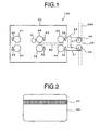
- Fig. 1 is a diagram showing the overall structure of a card processor according to the first embodiment of the present invention.
- a card processor 100 is mounted on, e.g., an ATM.
- Reference numeral 200 represents a housing of ATM.
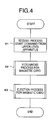
- a card 50 to be processed by the card processor 100 is a magnetic card having a magnetic stripe 51 such as shown in Fig. 2.
- Reference numeral 20 represents a main body of the card processor 100
- reference numeral 21 represents a card insertion unit mounted on the front side of the main body 20
- reference numeral 22 represents a card slot into which the card 50 is inserted.
- Reference numeral 23 represents a shutter which is opened and closed by a solenoid to be later described in an up/down direction as viewed in the figure, to thereby regulate advancement of the card 50 from the card slot 22 to the inside of the main body 20 and ejection of the card 50 from the inside of the main body 20 to the card slot 22.
- Reference numerals 24 to 27 each represent a pair of upper and lower transport rollers which transport the card 50 in a right/left direction as viewed in the figure by normal/reverse rotation of a motor to be described later.
- the transport rollers 25 to 27 are mounted inside the main body 20 and constitute first transport means according to the embodiment of the present invention.
- the transport rollers 24 are mounted near the card slot 22 of the card insertion unit 21 and constitute second transport means according to the embodiment of the present invention.
- the card processor is divided into the main body (inside the card processor) 20 and the insertion unit (outside the card processor) 21 by using as the reference the shutter 23 and sensor 32 shown in the figure.
- Reference numerals 31 to 24 represent card detection sensors each constituted of a photo microsensor provided with a pair of upper and lower light projection and reception elements.
- the sensor 31 is positioned near the card slot 22 of the card insertion unit 21 at generally the same position as that of the transport rollers 24, and constitutes detection means according to the embodiment of the present invention.
- the sensors 23 to 34 are mounted inside the main body 20.
- the sensor 32 is disposed just before the transport rollers 25, the sensor 33 is disposed just before the transport rollers 26, and the sensor 34 is disposed just after the transport rollers 27, respectively as viewed from the card slot 22.
- Reference numeral 2 represents a magnetic head for reading magnetic information from the magnetic stripe 51 of the card 50.
- the magnetic head 2 is disposed just after the transport rollers 26 as viewed from the card slot 22, and reads magnetic information by detecting a change in magnetic force of the magnetic stripe 51 during the state while the card 50 is transported by the rollers 26 and 27.
- Fig. 3 is a block diagram showing the electrical structure of the card processor 100.
- reference numeral 1 represents a control unit for controlling each unit of the card processor.
- the control unit is constituted of a CPU, a ROM, a RAM, a control circuit to be described later and the like.
- ROM stores an operation program and the like for CPU
- RAM stores readable and writable control data and the like to be used for CPU to control each unit.
- Reference numeral 2 represents the magnetic head described with reference to Fig. 1
- reference numeral 3 represents a sensor representative of all sensors 31 to 34 shown in Fig. 1
- reference numeral 4 represents a motor for rotating the transport rollers 24 to 27.
- the control unit 1 is provided with a motor control circuit for controlling and driving the motor 4.
- This motor control circuit drives the motor 4 for normal rotation or reverse rotation to rotate the transport rollers 24 to 27 and transport the card 50 along a predetermined direction.
- Reference numeral 5 represents a shutter solenoid for opening/closing the shutter 23.
- the control unit 1 is provided with a solenoid control circuit for controlling and driving the solenoid 5.
- the solenoid control circuit drives the solenoid 5 to open/close the shutter 23.
- Reference numeral 6 represents a communication unit for mutual communications with an upper level apparatus 10, the communication unit constituting communication means according to the embodiment of the present invention.
- the upper level apparatus 10 is, for example, ATM mounting the card processor 100.
- the control unit 1 transmits information read with the magnetic head 2 from the card 50 to the upper level apparatus 10 via the communication unit 6.
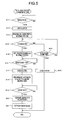
- Figs. 4 to 6 are flow charts illustrating the operation procedure of the card processor 100. Each process is executed by CPU of the control unit 1.
- Fig. 4 illustrates the outline operation
- Figs. 5 and 6 illustrate the partial detailed procedures.
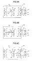
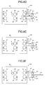
- Figs. 7A to 8F are diagrams showing the transport state of the card in the card processor 100. With reference to these figures, the operation of the card processor 100 will be described.
- the upper level apparatus 10 is ATM and the card processor 100 is mounted in ATM.
- the upper level apparatus 10 transmits a process start command to the card processor 100 and the communication unit 6 receives this command (Step S1).
- the card processor 100 fetches the card 50 and reads information recorded in the fetched card (Step S2).
- the card processor executes an ejection process for the card 50 (Step S3) to terminate a series of processes after ejection.
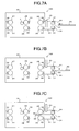
- Fig. 5 is a flow chart illustrating the detailed procedure of a magnetic card fetch/read process at Step S2 shown in Fig. 4. This procedure will now be described.
- the control unit 1 always monitors whether the sensor 31 mounted on the card slot 22 turns ON or not (Step S11).
- Fig. 7A shows the state before the card 50 is inserted into the card slot 22, and in this state, the sensor 31 is in an OFF state (NO at Step S11).
- the housing 200 of ATM shown in Fig. 1 is shown omitted (similar to the following figures).
- Step S11 the sensor 31 detects the card 50 and turns ON (YES at Step S11) so that the shutter solenoid 5 is driven and the shutter 23 opens (Step S12).
- the motor 4 is intermittently driven in a normal rotation so that the transport rollers 24 to 27 are also intermittently driven in the normal rotation (Step S13).
- the card 50 is fetched to the card insertion unit 21 while being transported intermittently by the transport rollers 24 immediately after inserted into the card slot 22.
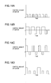
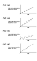
- a control amount (drive voltage) such as shown in Fig. 18A is supplied to the motor 4 from the motor drive circuit of the control unit 1, and the motor 4 performs an intermittent rotation operation such as shown in Fig. 19A.
- the motor 4 rotates by one unit rotation amount during one unit time, stops during the next one unit time, and repeats these operations.
- the card 50 transported to the position of the sensor 31 is transported intermittently in the left direction as viewed in the figure by the intermittently rotating transport rollers 24.
- the card 50 fetched from the card insertion unit 21 to the inside of the main body 20 is transported intermittently in succession in the left direction by the intermittently rotating transport rollers 25, as shown in Fig. 7C.
- the sensor 32 turns ON.
- Step S14 it is judged whether the sensor 33 turns ON.
- the sensor 33 detects the card 50 and turns ON (YES at Step S14).
- driving the motor 4 is switched from intermittent driving to continuous driving so that the motor 4 is driven continuously in a normal rotation operation.
- the transport rollers 24 to 27 are therefore driven continuously in the normal rotation operation (Step S15).
- the card 50 is transported continuously in the left direction in the figure by the continuously rotating transport rollers 25 and 26.
- Step S16 it is judged whether the sensor 32 changes from ON to OFF.
- Step S17 As shown in Fig. 7F, as the card 50 reaches the position of the magnetic head 2, the magnetic head 2 starts reading magnetic information (information recorded in the magnetic stripe 51) of the card 50 (Step S18).
- Step S19 the control unit 1 judges whether the sensor 34 turns ON (Step S19). As shown in Fig. 7H, as the card 50 is transported to the position of the sensor 34, the sensor 34 detects the card 50 and turns ON (YES at Step S19). In response to this, magnetic information reading with the magnetic head 2 is terminated (Step S20). As the sensor 34 turns ON, the control unit 1 judges that the card 50 was transported to the innermost of the card processor 100, and stops the motor 4. Therefore, rotation of the transport rollers 24 to 27 stops also (Step S21).
- Step S14 If it is judged at Step S14 that the sensor 33 does not turn ON (NO at Step S14), it is judged whether a predetermined time has elapsed since the sensor 31 turned ON (Step S22). If the predetermined time has not elapsed (NO at Step S22), then the flow returns to Step S14 whereat the state of the sensor 33 is monitored. If the sensor 33 does not turn ON (NO at Step S14) and the predetermined time has elapsed (YES at Step S22), it is judged that the card 50 is not fetched to the inside of the main body 20, and the shutter solenoid 5 closes the shutter 23 (Step S23) to thereafter terminate the process.
- the card 50 inserted into the card slot 22 is first transported intermittently, and after the card 50 is transported to the position of the sensor 33 in the main body 20, the card 50 is transported continuously.
- the position of the sensor 33 is set to a limit position where there is no risk that magnetic information of the card 50 is skimmed, i.e., to a front end (left end) position of the card 50 when the card 50 is fetched to the card insertion unit 21 at an inner position where magnetic information of the card 50 cannot be acquired normally with the skimmer SK.
- the card 50 is transported intermittently in the state that there is a risk of magnetic information skimming, to thereby prevent skimming, whereas the card 50 is transported continuously in the state that there is no risk of magnetic information skimming, to thereby fetch the card to the inside of the main body 20 at high speed.
- the control unit 1 After driving the motor 4 is stopped, the control unit 1 transmits information read from the card 50 with the magnetic head 2 to the upper level apparatus 10 via the communication unit 6. In accordance with the received card information, the upper level apparatus 10 performs a predetermined transaction process (e.g., cash payment). After the transaction process is completed, the upper level apparatus 10 notifies a process completion to the card processor 100. Upon reception of this notice at the communication unit 6, the control unit 1 executes the eject process (Step S3 in Fig. 4) for the card 50 in accordance with the procedure to be described hereunder.
- a predetermined transaction process e.g., cash payment
- Fig. 6 is a flow chart illustrating the detailed procedure of the eject process for the magnetic card at Step S3 shown in Fig. 4.
- the control unit 1 drives the motor 4 continuously in a reverse rotation operation so that the transport rollers 24 to 27 are also driven continuously in the reverse rotation operation (Step S31).
- the transport rollers 24 to 27 rotate in a reverse direction
- the card 50 at the position shown in Fig. 8A (the same position as that shown in Fig. 7H) is transported continuously by the transport rollers 26 and 27 in an eject direction (right direction in the figure) as shown in Fig. 8B.
- it is judged whether the sensor 32 turns ON (Step S32). As shown in Fig.
- the sensor 32 detects the card 50 and turns ON (YES at Step S32).
- the shutter solenoid 5 opens the shutter 23 (Step S33). The card 50 is therefore transported toward the card slot 22.
- Step S34 judges whether the sensor 31 turns ON (Step S34). As shown in Fig. 8D, as the card 50 is transported to the position of the sensor 31, the sensor 31 detects the card 50 and turns ON (YES at Step S34). In response to ON of the sensor 31, driving the motor 4 is switched from continuous driving to intermittent driving, and the motor 4 is driven intermittently in the reverse rotation operation. The transport rollers 24 to 27 are therefore driven intermittently in the reverse rotation operation (Step S35). Therefore, the card 50 is transported intermittently in the right direction in the figure by the intermittently rotating transport rollers 24 and 25, to thereby eject the card from the card slot 22 to the external, as shown in Fig. 8E. Driving the motor 4 is executed in the same way as that shown in Figs. 18A and 18B described previously.
- Step S36 After the transport rollers are started being intermittently rotated at Step S35, the control unit 1 monitors whether a predetermined time has elapsed since the sensor 31 turned ON (Step S36). If the predetermined time has elapsed (YES at Step S36), rotation of the transport rollers 24 to 27 is stopped (Step S37), and the shutter 23 is closed (Step S38). Therefore, as shown in Fig. 8F, the card 50 is returned via the card slot 22 in the state that the back end is held by a pair of transport rollers 24. With the processes described above, a series of transaction processes is completed at ATM using the magnetic card 50.
- the card 50 is transported continuously until the card is transported to the position of the sensor 31 mounted near the card slot 22, and the card 50 is transported intermittently after the card 50 is transported to the position of the sensor 31.
- the position of the sensor 31 is set to a limit position where there is a risk that magnetic information of the card 50 is skimmed, i.e., to a front end (right end) position of the card 50 when magnetic information of the card 50 can be acquired normally with the skimmer SK.
- the card 50 is transported continuously in the state that there is no risk of magnetic information skimming, to thereby shorten a card ejection time, whereas the card 50 is transported intermittently in the state that there is a risk of magnetic information skimming, to prevent skimming.
- the card 50 can be started being intermittently transported by the transport rollers 24 mounted near the card slot 22, approximately at the same time of card insertion. It is therefore possible to prevent skimming more effectively than the conventional example in which intermittent transportation starts when the card 50 reaches the transport rollers 25.
- the skimming capable range a occupies a dominantly larger ratio than the skimming incapable range b in the case of Fig. 22, whereas in the case of the present invention (Fig. 9), the skimming incapable range b occupies a dominantly larger ratio than the skimming capable range a . Therefore, even if magnetic information is acquired illegally by skimming, this skimming damage can be suppressed minimum.
- the timing when intermittent transportation of the card 50 starts can be set faster and the skimming capable range a of the card 50 can be made smaller, than that the sensor 31 is mounted inner than the transport rollers 24 as viewed from the card slot 22.
- a length length in the right/left direction in the figure
- Fig. 10 is a diagram showing the outline structure of a card processor according to the second embodiment of the present invention.
- the sensor 31 for detecting the card 50 is mounted near the card slot 22, and in response to detection of the card 50 with the sensor 31, the transport rollers 24 transport the card 50 intermittently.
- the sensor 31 is not provided, and the transport rollers 24 transport the card 50 in accordance with a command from the upper level apparatus 10.
- reference numeral 100 represents a card processor
- reference numeral 200 represents a housing of ATM
- reference numeral 50 represents a card such as shown in Fig. 2
- reference numeral 20 represents a main body of the card processor 100
- reference numeral 21 represents a card insertion unit
- reference numeral 22 represents a card slot
- reference numerals 24 to 27 represent transport rollers
- reference numerals 32 to 34 represent sensors
- reference numeral 2 represents a magnetic head.
- These components are similar to those described with reference to Fig. 1, and the detailed description thereof is omitted.
- a different point of the structure shown in Fig. 10 from that shown in Fig. 1 resides in that the sensor 31 and shutter 23 shown in Fig. 1 are omitted. However, the shutter 23 may be used.
- a block diagram of the card processor is the same as that shown in Fig. 3, except that the shutter solenoid 5 is omitted, and the detailed description thereof is also omitted.
- Step S1 upon reception of a process start command from the upper level apparatus 10 (Step S1), the card processor 100 fetches the card 50 and reads information (Step S2), and after completion of this process, executes an eject process for the card 50 (Step S3).
- Fig. 11 is a flow chart illustrating the detailed procedure of a magnetic card fetch/read process at Step S2 shown in Fig. 4. This procedure will now be described.
- the control unit 1 drives immediately the motor 4 in a normal rotation operation so that the transport rollers 24 to 27 are also intermittently driven in the normal rotation operation (Step S51). Namely, in this embodiment, as shown in Fig. 13A, the transport rollers 24 to 27 are driven intermittently before the card 50 is inserted into the card slot 22. Therefore, as shown in Fig.
- Step 52 it is judged whether the sensor 33 turns ON (Step 52).
- the sensor 33 detects the card 50 and turns ON (YES at Step S52).
- driving the motor 4 is switched from intermittent driving to continuous driving so that the motor 4 is driven continuously in a normal rotation operation.
- the transport rollers 24 to 27 are therefore driven continuously in the normal rotation operation (Step S53).
- the card 50 is transported continuously in the left direction in the figure by the continuously rotating transport rollers 25 and 26 as shown in Fig. 13E.
- Fig. 13F as the card 50 reaches the position of the magnetic head 2, the magnetic head 2 starts reading magnetic information (information recorded in the magnetic stripe 51) of the card 50 (Step S54).
- Step S55 judges whether the sensor 34 turns ON.
- the sensor 34 detects the card 50 and turns ON (YES at Step S55).
- magnetic information reading with the magnetic head 2 is terminated (Step S56).
- the control unit 1 judges that the card 50 was transported to the innermost of the card processor 100, and stops the motor 4. Therefore, rotation of the transport rollers 24 to 27 stops also (Step S57).
- the card 50 is transported intermittently by the transport rollers 24 mounted near the card slot 22. Therefore, similar to the case shown in Fig. 9, even if the skimmer SK is mounted on the card slot 22, information skimmed with the magnetic head H of the skimmer SK during card insertion is information to be read until the card 50 reaches the transport rollers 24, i.e., only little information recorded on the magnetic stripe 51 in the range a , and most of information recorded in the range b will not be skimmed. It is therefore possible to prevent skimming during card insertion as much as possible, even if the card 50 has a small amount of effective data.
- the card 50 inserted into the card slot 22 is first transported intermittently, and after the card 50 is transported to the position of the sensor 33 inside the main body 20, the card 50 is transmitted continuously.
- the position of the sensor 33 is set to a limit position where there is no risk that magnetic information of the card 50 is skimmed, i.e., to a front end (left end) position of the card 50 when the card 50 is fetched to the card insertion unit 21 at an inner position where magnetic information of the card 50 cannot be acquired normally with the skimmer SK.
- the card 50 is transported intermittently in the state that there is a risk of magnetic information skimming, to thereby prevent skimming, whereas the card 50 is transported continuously in the state that there is no risk of magnetic information skimming, to thereby fetch the card to the inside of the main body 20 at high speed.
- the control unit 1 After driving the motor 4 is stopped, the control unit 1 transmits information read from the card 50 with the magnetic head 2 to the upper level apparatus 10 via the communication unit 6. In accordance with the received card information, the upper level apparatus 10 performs a predetermined transaction process (e.g., cash payment). After the transaction process is completed, the upper level apparatus 10 notifies a process completion to the card processor 100. Upon reception of this notice at the communication unit 6, the control unit 1 executes the eject process (Step S3 in Fig. 4) for the card 50 in accordance with the procedure to be described hereunder.
- a predetermined transaction process e.g., cash payment
- Fig. 12 is a flow chart illustrating the detailed procedure of the eject process for the magnetic card at Step S3 shown in Fig. 4.
- the control unit 1 drives the motor 4 continuously in a reverse rotation operation so that the transport rollers 24 to 27 are also driven continuously in the reverse rotation operation (Step S71).
- the transport rollers 24 to 27 rotate in a reverse direction
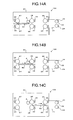
- the card 50 at the position shown in Fig. 14A (the same position as that shown in Fig. 13H) is transported continuously by the transport rollers 26 and 27 in the right direction as shown in Fig. 14B.
- Step S72 it is judged whether the sensor 32 turns ON
- the sensor 32 detects the card 50 and turns ON (YES at Step S72).
- Step S73 the card 50 is transported intermittently in the right direction in the figure by the intermittently rotating transport rollers 24 and 25, to be transported to the card slot 22, as shown in Fig. 14D.
- Driving the motor 4 is executed in the same way as that shown in Figs. 18A and 19A described previously.
- Step S74 judges whether the sensor 32 turns OFF. As shown in Fig. 14E, as the back end (left end) of the card 50 passes the position of the sensor 32, the sensor 32 turns OFF (YES at Step S74). As the sensor 32 turns OFF, then the control unit 1 monitors whether a predetermined time has elapsed (Step S75). During this monitoring, intermittent driving of the transport rollers 24 at Step S73 continues so that the card 50 is transported intermittently by the transport rollers 24 and ejected from the card slot 22 to the external.
- Step S75 the control unit 1 stops the motor 4 and rotation of the transport rollers 24 to 27 (Step S76). Therefore, as shown in Fig. 14F, the card 50 is returned from the card slot 22 in the state that the back end of the card is held by a pair of transport rollers 24. With the above processes, a series of transaction processes is completed at ATM using the card 50.
- the card 50 is transported continuously until the card 50 is transported to the position of the sensor 32, and the card 50 is transported intermittently after the card 50 is transported to the position of the sensor 32. Therefore, skimming can be prevented by intermittent transportation of the card 50 and a card ejection time can be shortened by continuous transportation of the card 50.
- the card 50 can be started being intermittently transported by the transport rollers 24 mounted near the card slot 22, approximately at the same time of card insertion. It is therefore possible to prevent skimming more effectively than the conventional example in which intermittent transportation starts when the card 50 reaches the transport rollers 25. Further, as already described through comparison between Figs. 9 and 22, even if information is skimmed, the amount of information is little so that a damage can be suppressed minimum according to the invention.
- the sensor 31 near the card slot 22 as in the first embodiment is not necessary so that the cost can be reduced correspondingly.
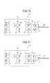
- Fig. 15 is a diagram showing the outline structure of a card processor according to the third embodiment of the present invention.
- like parts to those shown in Fig. 1 are represented by using identical reference numerals.
- a different point of a card processor 100 shown in Fig. 15 from that shown in Fig. 1 resides in that in addition to a sensor 31, a magnetic stripe detection sensor 41 is provided.
- This magnetic stripe detection sensor 41 constitutes judgement means according to the embodiment of the present invention.
- Other constituent elements are similar to those shown in Fig. 1 and the detailed description of Fig. 15 is omitted.
- the magnetic stripe detection sensor 41 judges whether or not the inserted card 50 is a magnetic card.
- the magnetic stripe detection sensor 41 is constituted of a magnetic head. If the card 50 is a magnetic card, the magnetic head reads magnetic information of the magnetic stripe and outputs a read signal, whereas if the card 50 is not a magnetic card, the magnetic head cannot read magnetic information and does not output a read signal. Therefore, it is possible to judge from presence/absence of the read signal from the sensor 41 whether the card 50 is a magnetic card. Since the sensor 41 has also a function of detecting insertion of the magnetic card, the sensor 31 of this embodiment may be omitted.
- Fig. 16 is a flow chart illustrating the outline operation of the card processor 100 shown in Fig. 15. Similar to Fig. 4, it is assumed herein that the upper level apparatus 10 is ATM and the card processor 100 is mounted in ATM. As a transaction is to be conducted at ATM by using the card 50, a user performs a predetermined operation by using a customer panel, the upper level apparatus 10 transmits a transaction start command to the card processor 100 and the card processor 100 starts card processing. First, as the card 50 is inserted into the card slot 22 (Step S101), it is judged from an output from the magnetic stripe detection sensor 41 whether the card 50 is a magnetic card (Step S102).
- Step S102 If the card 50 is a magnetic card (YES at Step S102), the flow advances to Step S103 whereat a magnetic card fetch/read process is executed. After this process is completed, a magnetic card eject process is executed (Step S104).
- Step S103 and S104 The detailed procedures of Steps S103 and S104 are similar to those shown in Figs. 5 and 6, and the description thereof is omitted. If the card 50 is not a magnetic card (NO at Step S102), the procedure is terminated or the transport rollers 24 are rotated reversely to return the card 50.
- skimming can be prevented effectively similar to the first and second embodiments. Further, it is judged whether the card 50 is a magnetic card before the card 50 is fetched to the inside of the card processor 100, and only if the card 50 is a magnetic card, the card 50 is fetched. Therefore, there is no fear that a card different from the magnetic card, foreign matters and the like are fetched erroneously, and it is possible to prevent beforehand jamming of a card in the card processor 100 and damages of a transport mechanism, magnetic head 2 and the like.
- the present invention can adopt various other embodiments in addition to the embodiments described above.
- the position of the sensor 31 is not limited to any specific position if the sensor is mounted near the transport rollers 24.
- the sensor 31 may be mounted at a position near the transport rollers 24 on the side of the shutter 23.
- card transportation is switched from intermittent transportation to continuous transportation at the time when the sensor 33 turns ON (Steps S14 and S15 in Fig. 5, Steps S52 and S53 in Fig. 1).
- card transportation may be switched from intermittent transportation to continuous transportation at the time when the sensor 31 turns OFF or when the sensor 32 turns OFF.
- transportation of the card 50 is switched from continuous transportation to intermittent transportation at the time when the sensor 31 turns ON (Steps S34 and S35 in Fig. 6).
- transportation of the card 50 may be switched from continuous transportation to intermittent transportation at the time when the sensor 33 turns OFF.
- transportation of the card 50 is switched from continuous transportation to intermittent transportation at the time when the sensor 32 turns ON (Steps S72 and S73 in Fig. 12).
- transportation of the card 50 may be switched from continuous transportation to intermittent transportation, at the time when a timer time has elapsed corresponding to the time required for the front end (right end) of the card 50 moves from the position of the sensor 32 to the card slot 22, by starting a timer at the time when the sensor 32 turns ON.
- control amounts such as shown in Figs. 18B to 18D may be supplied to the motor 4 to perform intermittent rotation operations of the motor 4 such as shown in Figs. 19B to 19D.
- the motor 4 rotates normally by a two-unit rotation amount during one unit time and rotates reversely by one unit rotation amount during next one unit time, these operations being repeated.
- Fig. 19B the motor 4 rotates normally by a two-unit rotation amount during one unit time and rotates reversely by one unit rotation amount during next one unit time, these operations being repeated.
- the motor 4 rotates normally by a two-unit rotation amount during one unit time, stops during next one unit time, rotates reversely by one unit rotation amount during next one unit time, and stops during next one unit time, these operations being repeated.
- the rotation time and stop time shown in Fig. 19A are made irregular to repeat randomly rotation and stop.
- the rotation time and stop time may be made irregular to repeat randomly rotation and stop.
- the sensors 31 to 34 constituted of photo microsensors are used illustratively as position detection means for detecting a position of the card 50.
- the position detection means may be a rotary encoder which outputs a signal corresponding to a revolution amount of the transport rollers 24 to 27 and motor 4.
- a revolution amount of the transport rollers or motor is calculated from an output signal of the rotary encoder, and a position of the card 50 can be detected from the calculated revolution amount.
- a timer and a calculator may be used as the position detection means. In this case, a motion distance of the card is calculated by the calculator in accordance with a timer measurement time and a card transportation speed to detect a position of the card from the calculated motion distance.
- the card processor 100 is mounted in ATM illustratively.
- the card processor of the present invention may be mounted in various apparatus such as CD (automatic cash dispenser), automatic ticket seller, and goods seller.
Landscapes
- Physics & Mathematics (AREA)
- General Physics & Mathematics (AREA)
- Engineering & Computer Science (AREA)
- Theoretical Computer Science (AREA)
- Business, Economics & Management (AREA)
- Accounting & Taxation (AREA)
- Finance (AREA)
- Control Of Vending Devices And Auxiliary Devices For Vending Devices (AREA)
- Conveying Record Carriers (AREA)
Abstract
Description
- The present invention relates to a card processor for processing a card recorded with magnetic information.
- A card processor for processing a magnetic card recorded with magnetic information is mounted in an automatic cash depositing/paying machine (hereinafter called "ATM") in banks. In the card processor, as a magnetic card is inserted into a card slot, the magmatic card is transported at a constant speed by transport means such as a motor and transport rollers, and a magnetic head reads magnetic information recorded on a magnetic stripe of the card. In addition to information read, the card processor writes information when necessary. As the read/write process is completed for the card, the card is ejected out to an external by transport means.
- In front of a true card processor mounted in ATM installed in banks or the like, a false card reader (skimmer) is installed in some cases in an attempt to illegally acquire card information of a magnetic card. This skimmer is equipped with a memory for storing information read from the magnetic card. As a user inserts a magnetic card into a card slot of the skimmer, without knowing an installation of such a skimmer or erroneously recognizing that the skimmer is a portion of a true card processor, information on the magnetic card is recorded by the skimmer and stored in the memory. The magnetic card inserted into the skimmer is transported to the true card processor whereat a usual card read process is executed. In this case, so long as the magnetic card is not a false card, the normal process is executed in ATM. After the card process is completed, the true card processor ejects the magnetic card and returns it to the user via the card slot of the skimmer. Since the card is returned normally, the user is difficult to notice that the card information was read illegally. Furthermore, card information may be read by the skimmer while the card is returned. A person who installed the skimmer dismounts it from ATM, reads illegally read card information from the memory, and forges a card in accordance with the card information.
- Unauthorized acquisition of card information with such a skimmer is called "skimming". As a countermeasure for preventing skimming, there is a technique of intermittently transporting a magnetic card while it is inserted or ejected (for example, refer to
JP-A-2005-128668 JP-A-2004-171205 US. Patent No. 6,460,771 ). Furthermore, there is a technique of temporarily stopping transportation of a magnetic card during insertion or ejection of the magnetic card in the state that a portion of the card is partially projected from a card slot to an external (For example, refer toJP-A-2001-22894 - Fig. 20 is a schematic diagram showing an example of the structure of a
card processor 100 mounted in ATM or the like. Thecard processor 100 is constituted of: amain body 20 thereof; acard insertion unit 21 mounted on the front side of themain body 20; acard slot 22 into which amagnetic card 50 is inserted; ashutter 23 for regulating insertion or ejection of themagnetic card 50;transport rollers 25 to 27 for transporting themagnetic card 50;sensors magnetic card 50 and amagnetic head 2 for reading information recorded in themagnetic card 50. Thecard processor 100 mounted in ATM or the like is generally equipped with thecard insertion unit 21. Thecard insertion unit 21 is a functionally essential unit for coupling thecard processor 100 to ahousing 200 of ATM or the like and assembling therein thecard detection sensor 30,shutter 23 and the like. Existence of thecard insertion unit 21 provides a length of several 10 mm from thecard slot 22 to thetransport rollers 25. - Information is recorded on a magnetic stripe of the
magnetic card 50, generally at the front end portion of the card. Figs. 21A and 21B are diagrams showing an information record format in the case that themagnetic card 50 is a cash card. Amagnetic stripe 51 is constituted of a field 51a where start code is recorded, afield 51b where effective data is recorded, afield 51c where dummy data is recorded, and afield 51d where end code is recorded. The effectivedata record field 51b records data necessary for transaction processes such as a bank number, a branch number, an account number and a card type, and the dummydata record field 51c records meaning-less data such as "00000,,,". Which type of information is recorded on themagnetic stripe 51 can be selected by monetary institutes to some extent. Therefore, there are a magnetic card 50 (cash card) having a large amount of effective data such as shown in Fig. 21A and a magnetic card 50 (cash card) having a small amount of effective data such as shown in Fig. 21B. - Therefore, in the
card processor 100 equipped with the above-describedcard insertion unit 21, as shown in Fig. 22, if a false reader (skimmer) SK is mounted on thecard slot 22, information recorded on themagnetic stripe 51 in a range a is skimmed with a magnetic head H built in the skimmer SK before the insertedmagnetic card 50 reaches thetransport rollers 25, because intermittent transportation of thetransport rollers 25 will not start until the front end of themagnetic card 50 is detected with thesensor 32 according to conventional techniques. Only information in a range b will not be skimmed after the start of intermittent transportation. As a result, most of information recorded in themagnetic card 50 is read illegally. 70 % to 80 % of information on themagnetic stripe 51 is read illegally depending upon a length of thecard insertion unit 21, a distance from thecard insertion unit 21 to thetransport rollers 25, and a position of the magnetic head H of the skimmer SK. As a result, particularly in the case of themagnetic card 50 having a small effective data field such as shown in Fig. 21B, all effective data is skimmed before card intermittent transportation even if intermittent transportation is performed. Not only during card insertion, but also during card ejection, while themagnetic card 50 is pulled out by a hand after it passed through thetransport rollers 25, most of information recorded in themagnetic card 50 is read from the same reason described above. - An issue addressed by the present invention is therefore to effectively prevent unauthorized acquisition of card information by a skimmer mounted on a card slot of a card processor provided with a magnetic card intermittent transportation function.
- A card processor of the present invention for processing a card recorded with magnetic information comprises: first transport means disposed in a main body of the card processor, the first transport means transporting the card; a card insertion unit mounded on the main body on a front side thereof for guiding the card inserted into a card slot to the first transport means; and second transport means disposed near the card slot of the card insertion unit, wherein the second transport means intermittently transports the card inserted into the card slot and/or the card to be ejected from the card slot.
- The second transport means for intermittently transporting the card is mounted near the card slot so that the card can be intermittently transported generally at the same time when the card is inserted. Accordingly, even if a skimmer is mounted on the card slot, there is almost no risk that card information is skimmed until the card reaches the first transport means. Also when the card is ejected, the card can be transported intermittently approximately at the same time when the card reaches the card slot. Therefore, at the stage when the card is pulled out with a hand, there is almost no risk that the card information is skimmed with the skimmer.
- Intermittent transportation of the present invention includes not only intermittent transportation of a regular period but also intermittent transportation of an irregular period. Intermittent transportation of the present invention includes not only intermittent transportation only in one direction but also intermittent transportation alternately repeating motions in one direction and in another direction to move eventually in one direction. When a card is fetched, it is desired to perform intermittent transportation only at an initial stage in order to shorten a fetch time. However, the present invention does not exclude that intermittent transportation is performed during the period from the start to the end of card fetch. Similarly, when a card is ejected, it is desired to perform intermittent transportation only at a final stage in order to shorten an eject time. However, the present invention does not exclude that intermittent transportation is performed during the period from the start to the end of card ejection. Intermittent transportation may be performed during one of card fetch and card ejection or during both.
- According to the present invention, it is substantially impossible to read information recorded in a card during card insertion or ejection with a skimmer mounted on a card slot of a card processor equipped with the card insertion unit. It is therefore possible to more effectively prevent skimming even for a magnetic card having a small amount of effective data.
- Other objects, features and advantages of the invention will become apparent from the following description of the embodiments of the invention taken in conjunction with the accompanying drawings.
-
- Fig. 1 is a schematic diagram showing the structure of a card processor according to a first embodiment of the present invention.
- Fig. 2 is a diagram showing a magnetic card.
- Fig. 3 is a block diagram illustrating an electrical structure of the card processor.
- Fig. 4 is a flow chart illustrating the outline operation of the card processor.
- Fig. 5 is a flow chart illustrating the detailed procedure of a card fetch/read process.
- Fig. 6 is a flow chart illustrating the detailed procedure of a card ejection process.
- Figs. 7A to 7H are diagrams illustrating a card fetch/read operation.
- Figs. 8A to 8F are diagrams illustrating a card ejection operation.
- Fig. 9 is a diagram illustrating skimming according to the present invention.
- Fig. 10 is a schematic diagram showing the structure of a card processor according to a second embodiment of the present invention.
- Fig. 11 is a flow chart illustrating the detailed procedure of a card fetch/read process.
- Fig. 12 is a flow chart illustrating the detailed procedure of a card ejection process.
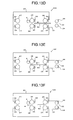
- Figs. 13A to 13H are diagrams illustrating a card fetch/read operation.
- Figs. 14A to 14F are diagrams illustrating a card ejection operation.
- Fig. 15 is a schematic diagram showing the structure of a card processor according to a third embodiment of the present invention.
- Fig. 16 is a flow chart illustrating an outline operation of the card processor.
- Fig. 17 is a schematic structural diagram showing another example of sensors.
- Figs. 18A to 18D show examples of a control amount applied to a motor.
- Figs. 19A to 19D are diagrams illustrating an intermittent rotation operation of a motor.
- Fig. 20 is a schematic diagram showing the structure of a card processor.
- Figs. 21A and 21B are diagrams illustrating record information of cards.
- Fig. 22 is a diagram illustrating skimming.
- Fig. 1 is a diagram showing the overall structure of a card processor according to the first embodiment of the present invention. Referring to Fig. 1, a
card processor 100 is mounted on, e.g., an ATM.Reference numeral 200 represents a housing of ATM. Acard 50 to be processed by thecard processor 100 is a magnetic card having amagnetic stripe 51 such as shown in Fig. 2.Reference numeral 20 represents a main body of thecard processor 100,reference numeral 21 represents a card insertion unit mounted on the front side of themain body 20, andreference numeral 22 represents a card slot into which thecard 50 is inserted.Reference numeral 23 represents a shutter which is opened and closed by a solenoid to be later described in an up/down direction as viewed in the figure, to thereby regulate advancement of thecard 50 from thecard slot 22 to the inside of themain body 20 and ejection of thecard 50 from the inside of themain body 20 to thecard slot 22. -
Reference numerals 24 to 27 each represent a pair of upper and lower transport rollers which transport thecard 50 in a right/left direction as viewed in the figure by normal/reverse rotation of a motor to be described later. Thetransport rollers 25 to 27 are mounted inside themain body 20 and constitute first transport means according to the embodiment of the present invention. Thetransport rollers 24 are mounted near thecard slot 22 of thecard insertion unit 21 and constitute second transport means according to the embodiment of the present invention. In the present invention, the card processor is divided into the main body (inside the card processor) 20 and the insertion unit (outside the card processor) 21 by using as the reference theshutter 23 andsensor 32 shown in the figure. -
Reference numerals 31 to 24 represent card detection sensors each constituted of a photo microsensor provided with a pair of upper and lower light projection and reception elements. Thesensor 31 is positioned near thecard slot 22 of thecard insertion unit 21 at generally the same position as that of thetransport rollers 24, and constitutes detection means according to the embodiment of the present invention. Thesensors 23 to 34 are mounted inside themain body 20. Thesensor 32 is disposed just before thetransport rollers 25, thesensor 33 is disposed just before thetransport rollers 26, and thesensor 34 is disposed just after thetransport rollers 27, respectively as viewed from thecard slot 22.Reference numeral 2 represents a magnetic head for reading magnetic information from themagnetic stripe 51 of thecard 50. Themagnetic head 2 is disposed just after thetransport rollers 26 as viewed from thecard slot 22, and reads magnetic information by detecting a change in magnetic force of themagnetic stripe 51 during the state while thecard 50 is transported by therollers - Fig. 3 is a block diagram showing the electrical structure of the
card processor 100. In Fig. 3,reference numeral 1 represents a control unit for controlling each unit of the card processor. The control unit is constituted of a CPU, a ROM, a RAM, a control circuit to be described later and the like. ROM stores an operation program and the like for CPU, and RAM stores readable and writable control data and the like to be used for CPU to control each unit.Reference numeral 2 represents the magnetic head described with reference to Fig. 1,reference numeral 3 represents a sensor representative of allsensors 31 to 34 shown in Fig. 1, and reference numeral 4 represents a motor for rotating thetransport rollers 24 to 27. Thecontrol unit 1 is provided with a motor control circuit for controlling and driving the motor 4. This motor control circuit drives the motor 4 for normal rotation or reverse rotation to rotate thetransport rollers 24 to 27 and transport thecard 50 along a predetermined direction.Reference numeral 5 represents a shutter solenoid for opening/closing theshutter 23. Thecontrol unit 1 is provided with a solenoid control circuit for controlling and driving thesolenoid 5. The solenoid control circuit drives thesolenoid 5 to open/close theshutter 23. Reference numeral 6 represents a communication unit for mutual communications with anupper level apparatus 10, the communication unit constituting communication means according to the embodiment of the present invention. Theupper level apparatus 10 is, for example, ATM mounting thecard processor 100. Thecontrol unit 1 transmits information read with themagnetic head 2 from thecard 50 to theupper level apparatus 10 via the communication unit 6. - Figs. 4 to 6 are flow charts illustrating the operation procedure of the
card processor 100. Each process is executed by CPU of thecontrol unit 1. Fig. 4 illustrates the outline operation, and Figs. 5 and 6 illustrate the partial detailed procedures. Figs. 7A to 8F are diagrams showing the transport state of the card in thecard processor 100. With reference to these figures, the operation of thecard processor 100 will be described. - First, the overall outline operation will be described with reference to Fig. 4. It is assumed herein that the
upper level apparatus 10 is ATM and thecard processor 100 is mounted in ATM. As a transaction is to be conducted at ATM by using thecard 50, a user performs a predetermined operation by using a customer panel, theupper level apparatus 10 transmits a process start command to thecard processor 100 and the communication unit 6 receives this command (Step S1). Upon reception of this command, thecard processor 100 fetches thecard 50 and reads information recorded in the fetched card (Step S2). After these processes, the card processor executes an ejection process for the card 50 (Step S3) to terminate a series of processes after ejection. - Fig. 5 is a flow chart illustrating the detailed procedure of a magnetic card fetch/read process at Step S2 shown in Fig. 4. This procedure will now be described. The
control unit 1 always monitors whether thesensor 31 mounted on thecard slot 22 turns ON or not (Step S11). Fig. 7A shows the state before thecard 50 is inserted into thecard slot 22, and in this state, thesensor 31 is in an OFF state (NO at Step S11). In this figure, thehousing 200 of ATM shown in Fig. 1 is shown omitted (similar to the following figures). - Next, as shown in Fig. 7B, as a user inserts the
card 50 into thecard slot 22 and the front end (left end) of thecard 50 reaches the position of thesensor 31, thesensor 31 detects thecard 50 and turns ON (YES at Step S11) so that theshutter solenoid 5 is driven and theshutter 23 opens (Step S12). In succession, the motor 4 is intermittently driven in a normal rotation so that thetransport rollers 24 to 27 are also intermittently driven in the normal rotation (Step S13). As a result, thecard 50 is fetched to thecard insertion unit 21 while being transported intermittently by thetransport rollers 24 immediately after inserted into thecard slot 22. - In this case, for example, a control amount (drive voltage) such as shown in Fig. 18A is supplied to the motor 4 from the motor drive circuit of the
control unit 1, and the motor 4 performs an intermittent rotation operation such as shown in Fig. 19A. In the case of Fig. 19A, the motor 4 rotates by one unit rotation amount during one unit time, stops during the next one unit time, and repeats these operations. As a result, thecard 50 transported to the position of thesensor 31 is transported intermittently in the left direction as viewed in the figure by the intermittently rotatingtransport rollers 24. Thecard 50 fetched from thecard insertion unit 21 to the inside of themain body 20 is transported intermittently in succession in the left direction by the intermittently rotatingtransport rollers 25, as shown in Fig. 7C. During the stage while thecard 50 is transported to the position of thetransport rollers 25, thesensor 32 turns ON. - Next, it is judged whether the
sensor 33 turns ON (Step S14). As shown in Fig. 7D, as thecard 50 is transported to the position of thesensor 33, thesensor 33 detects thecard 50 and turns ON (YES at Step S14). In response to this, driving the motor 4 is switched from intermittent driving to continuous driving so that the motor 4 is driven continuously in a normal rotation operation. Thetransport rollers 24 to 27 are therefore driven continuously in the normal rotation operation (Step S15). As a result, thecard 50 is transported continuously in the left direction in the figure by the continuously rotatingtransport rollers sensor 32 changes from ON to OFF (Step S16). As shown in Fig. 7E, as the back end (right end) of thecard 50 passes through thesensor 32, thesensor 32 changes from ON to OFF (YES at Step S16). In response to this, theshutter solenoid 5 closes the shutter 23 (Step S17). As shown in Fig. 7F, as thecard 50 reaches the position of themagnetic head 2, themagnetic head 2 starts reading magnetic information (information recorded in the magnetic stripe 51) of the card 50 (Step S18). - Thereafter, as shown in Fig. 7G, the
card 50 is transported continuously by thetransport rollers card 50 is read with themagnetic head 2. Thecontrol unit 1 judges whether thesensor 34 turns ON (Step S19). As shown in Fig. 7H, as thecard 50 is transported to the position of thesensor 34, thesensor 34 detects thecard 50 and turns ON (YES at Step S19). In response to this, magnetic information reading with themagnetic head 2 is terminated (Step S20). As thesensor 34 turns ON, thecontrol unit 1 judges that thecard 50 was transported to the innermost of thecard processor 100, and stops the motor 4. Therefore, rotation of thetransport rollers 24 to 27 stops also (Step S21). - If it is judged at Step S14 that the
sensor 33 does not turn ON (NO at Step S14), it is judged whether a predetermined time has elapsed since thesensor 31 turned ON (Step S22). If the predetermined time has not elapsed (NO at Step S22), then the flow returns to Step S14 whereat the state of thesensor 33 is monitored. If thesensor 33 does not turn ON (NO at Step S14) and the predetermined time has elapsed (YES at Step S22), it is judged that thecard 50 is not fetched to the inside of themain body 20, and theshutter solenoid 5 closes the shutter 23 (Step S23) to thereafter terminate the process. - As described above, in the procedure shown in Fig. 5, approximately at the same time when the
card 50 is inserted, thecard 50 is transported intermittently by thetransport rollers 24 mounted near thecard slot 22. Therefore, as shown in Fig. 9, even if the skimmer SK is mounted on thecard slot 22, information skimmed with a magnetic head H of the skimmer SK during card insertion is information to be read until thecard 50 reaches thetransport rollers 24, i.e., only little information recorded on themagnetic stripe 51 in a range (a), and most of information recorded in a range b will not be skimmed. It is therefore possible to prevent skimming during card insertion as much as possible, even if thecard 50 has a small amount of effective data. - Further, in the procedure shown in Fig. 5, at the stage while the
card 50 is fetched to the inside of themain body 20 of the card processor, thecard 50 inserted into thecard slot 22 is first transported intermittently, and after thecard 50 is transported to the position of thesensor 33 in themain body 20, thecard 50 is transported continuously. The position of thesensor 33 is set to a limit position where there is no risk that magnetic information of thecard 50 is skimmed, i.e., to a front end (left end) position of thecard 50 when thecard 50 is fetched to thecard insertion unit 21 at an inner position where magnetic information of thecard 50 cannot be acquired normally with the skimmer SK. With this setting, thecard 50 is transported intermittently in the state that there is a risk of magnetic information skimming, to thereby prevent skimming, whereas thecard 50 is transported continuously in the state that there is no risk of magnetic information skimming, to thereby fetch the card to the inside of themain body 20 at high speed. - After driving the motor 4 is stopped, the
control unit 1 transmits information read from thecard 50 with themagnetic head 2 to theupper level apparatus 10 via the communication unit 6. In accordance with the received card information, theupper level apparatus 10 performs a predetermined transaction process (e.g., cash payment). After the transaction process is completed, theupper level apparatus 10 notifies a process completion to thecard processor 100. Upon reception of this notice at the communication unit 6, thecontrol unit 1 executes the eject process (Step S3 in Fig. 4) for thecard 50 in accordance with the procedure to be described hereunder. - Fig. 6 is a flow chart illustrating the detailed procedure of the eject process for the magnetic card at Step S3 shown in Fig. 4. As the eject process starts, the
control unit 1 drives the motor 4 continuously in a reverse rotation operation so that thetransport rollers 24 to 27 are also driven continuously in the reverse rotation operation (Step S31). As thetransport rollers 24 to 27 rotate in a reverse direction, thecard 50 at the position shown in Fig. 8A (the same position as that shown in Fig. 7H) is transported continuously by thetransport rollers sensor 32 turns ON (Step S32). As shown in Fig. 8C, as the front end (right end) of thecard 50 reaches the position of thesensor 32, thesensor 32 detects thecard 50 and turns ON (YES at Step S32). In response to this, theshutter solenoid 5 opens the shutter 23 (Step S33). Thecard 50 is therefore transported toward thecard slot 22. - After the
shutter 23 opens, thecontrol unit 1 judges whether thesensor 31 turns ON (Step S34). As shown in Fig. 8D, as thecard 50 is transported to the position of thesensor 31, thesensor 31 detects thecard 50 and turns ON (YES at Step S34). In response to ON of thesensor 31, driving the motor 4 is switched from continuous driving to intermittent driving, and the motor 4 is driven intermittently in the reverse rotation operation. Thetransport rollers 24 to 27 are therefore driven intermittently in the reverse rotation operation (Step S35). Therefore, thecard 50 is transported intermittently in the right direction in the figure by the intermittently rotatingtransport rollers card slot 22 to the external, as shown in Fig. 8E. Driving the motor 4 is executed in the same way as that shown in Figs. 18A and 18B described previously. - After the transport rollers are started being intermittently rotated at Step S35, the
control unit 1 monitors whether a predetermined time has elapsed since thesensor 31 turned ON (Step S36). If the predetermined time has elapsed (YES at Step S36), rotation of thetransport rollers 24 to 27 is stopped (Step S37), and theshutter 23 is closed (Step S38). Therefore, as shown in Fig. 8F, thecard 50 is returned via thecard slot 22 in the state that the back end is held by a pair oftransport rollers 24. With the processes described above, a series of transaction processes is completed at ATM using themagnetic card 50. - As described above, in the procedure shown in Fig. 6, intermittent transportation is performed until the
card 50 is nearly ejected from thecard slot 22 by thetransport rollers 24 mounted near thecard slot 22. Therefore, as shown in Fig. 9, even if the skimmer SK is mounted on thecard slot 22, information skimmed with the magnetic head H of the skimmer SK during card ejection is information to be read after thecard 50 departs from thetransport rollers 24, i.e., only little information recorded on themagnetic stripe 51 in the range (a), and most of information recorded in the range b will not be skimmed. It is therefore possible to prevent skimming during card ejection as much as possible, even if thecard 50 has a small amount of effective data. - Further, in the procedure shown in Fig. 6, at the stage while the
card 50 is ejected to the outside of themain body 20 of the card processor, thecard 50 is transported continuously until the card is transported to the position of thesensor 31 mounted near thecard slot 22, and thecard 50 is transported intermittently after thecard 50 is transported to the position of thesensor 31. The position of thesensor 31 is set to a limit position where there is a risk that magnetic information of thecard 50 is skimmed, i.e., to a front end (right end) position of thecard 50 when magnetic information of thecard 50 can be acquired normally with the skimmer SK. With this setting, thecard 50 is transported continuously in the state that there is no risk of magnetic information skimming, to thereby shorten a card ejection time, whereas thecard 50 is transported intermittently in the state that there is a risk of magnetic information skimming, to prevent skimming. - As described above, according to the first embodiment, even if there is a distance from the
card slot 22 to transportrollers 25 because of existence of thecard insertion unit 21, thecard 50 can be started being intermittently transported by thetransport rollers 24 mounted near thecard slot 22, approximately at the same time of card insertion. It is therefore possible to prevent skimming more effectively than the conventional example in which intermittent transportation starts when thecard 50 reaches thetransport rollers 25. Further as apparent from comparison between Figs. 9 and 22, even if magnetic information of thecard 50 is skimmed, the skimming capable range a occupies a dominantly larger ratio than the skimming incapable range b in the case of Fig. 22, whereas in the case of the present invention (Fig. 9), the skimming incapable range b occupies a dominantly larger ratio than the skimming capable range a. Therefore, even if magnetic information is acquired illegally by skimming, this skimming damage can be suppressed minimum. - Further, according to the first embodiment, near at the
card slot 22, since thesensor 31 for detecting insertion of thecard 50 is mounted at the position of thetransport rollers 24, the timing when intermittent transportation of thecard 50 starts can be set faster and the skimming capable range a of thecard 50 can be made smaller, than that thesensor 31 is mounted inner than thetransport rollers 24 as viewed from thecard slot 22. In addition, a length (length in the right/left direction in the figure) can be reduced more than that thesensor 31 is mounted outer than thetransport rollers 24 as viewed from thecard slot 22. - Fig. 10 is a diagram showing the outline structure of a card processor according to the second embodiment of the present invention. In the first embodiment, the
sensor 31 for detecting thecard 50 is mounted near thecard slot 22, and in response to detection of thecard 50 with thesensor 31, thetransport rollers 24 transport thecard 50 intermittently. In the second embodiment, thesensor 31 is not provided, and thetransport rollers 24 transport thecard 50 in accordance with a command from theupper level apparatus 10. - In Fig. 10,
reference numeral 100 represents a card processor,reference numeral 200 represents a housing of ATM,reference numeral 50 represents a card such as shown in Fig. 2,reference numeral 20 represents a main body of thecard processor 100,reference numeral 21 represents a card insertion unit,reference numeral 22 represents a card slot,reference numerals 24 to 27 represent transport rollers,reference numerals 32 to 34 represent sensors, andreference numeral 2 represents a magnetic head. These components are similar to those described with reference to Fig. 1, and the detailed description thereof is omitted. A different point of the structure shown in Fig. 10 from that shown in Fig. 1 resides in that thesensor 31 andshutter 23 shown in Fig. 1 are omitted. However, theshutter 23 may be used. A block diagram of the card processor is the same as that shown in Fig. 3, except that theshutter solenoid 5 is omitted, and the detailed description thereof is also omitted. - Next, description will be made on the operation of the
card processor 100 shown in Fig. 10. The overall outline operation is the same as that illustrated in the flow chart of Fig. 4. Namely, upon reception of a process start command from the upper level apparatus 10 (Step S1), thecard processor 100 fetches thecard 50 and reads information (Step S2), and after completion of this process, executes an eject process for the card 50 (Step S3). - Fig. 11 is a flow chart illustrating the detailed procedure of a magnetic card fetch/read process at Step S2 shown in Fig. 4. This procedure will now be described. Upon reception of a process start command from the
upper level apparatus 10 at Step S1 shown in Fig. 4, thecontrol unit 1 drives immediately the motor 4 in a normal rotation operation so that thetransport rollers 24 to 27 are also intermittently driven in the normal rotation operation (Step S51). Namely, in this embodiment, as shown in Fig. 13A, thetransport rollers 24 to 27 are driven intermittently before thecard 50 is inserted into thecard slot 22. Therefore, as shown in Fig. 13B, as thecard 50 is inserted into thecard slot 22 to the position of thetransport rollers 24, while thecard 50 is intermittently transported by thetransport rollers 24 immediately after thecard 50 is inserted into thecard slot 22, thecard 50 is fetched to the inside of themain body 20 via thecard slot 21 as shown in Fig. 13C. In this case, a control amount (drive voltage) such as shown in Fig. 18A is supplied to the motor 4 from the motor drive circuit of thecontrol unit 1 so that the motor 4 performs an intermittent rotation operation such as shown in Fig. 19A. This operation has been described earlier. - Next, it is judged whether the
sensor 33 turns ON (Step 52). As shown in Fig. 13D, as thecard 50 is transported to the position of thesensor 33, thesensor 33 detects thecard 50 and turns ON (YES at Step S52). In response to this, driving the motor 4 is switched from intermittent driving to continuous driving so that the motor 4 is driven continuously in a normal rotation operation. Thetransport rollers 24 to 27 are therefore driven continuously in the normal rotation operation (Step S53). As a result, thecard 50 is transported continuously in the left direction in the figure by the continuously rotatingtransport rollers card 50 reaches the position of themagnetic head 2, themagnetic head 2 starts reading magnetic information (information recorded in the magnetic stripe 51) of the card 50 (Step S54). - Thereafter, as shown in Fig. 13G, the
card 50 is transported continuously by thetransport rollers card 50 is read with themagnetic head 2. Thecontrol unit 1 judges whether thesensor 34 turns ON (Step S55). As shown in Fig. 13H, as thecard 50 is transported to the position of thesensor 34, thesensor 34 detects thecard 50 and turns ON (YES at Step S55). In response to this, magnetic information reading with themagnetic head 2 is terminated (Step S56). As thesensor 34 turns ON, thecontrol unit 1 judges that thecard 50 was transported to the innermost of thecard processor 100, and stops the motor 4. Therefore, rotation of thetransport rollers 24 to 27 stops also (Step S57). - As described above, in the procedure shown in Fig. 11, approximately at the same time of card insertion, the
card 50 is transported intermittently by thetransport rollers 24 mounted near thecard slot 22. Therefore, similar to the case shown in Fig. 9, even if the skimmer SK is mounted on thecard slot 22, information skimmed with the magnetic head H of the skimmer SK during card insertion is information to be read until thecard 50 reaches thetransport rollers 24, i.e., only little information recorded on themagnetic stripe 51 in the range a, and most of information recorded in the range b will not be skimmed. It is therefore possible to prevent skimming during card insertion as much as possible, even if thecard 50 has a small amount of effective data. - Further, in the procedure shown in Fig. 11, at the stage while the
card 50 is fetched to the inside of themain body 20 of the card processor, thecard 50 inserted into thecard slot 22 is first transported intermittently, and after thecard 50 is transported to the position of thesensor 33 inside themain body 20, thecard 50 is transmitted continuously. The position of thesensor 33 is set to a limit position where there is no risk that magnetic information of thecard 50 is skimmed, i.e., to a front end (left end) position of thecard 50 when thecard 50 is fetched to thecard insertion unit 21 at an inner position where magnetic information of thecard 50 cannot be acquired normally with the skimmer SK. With this setting, thecard 50 is transported intermittently in the state that there is a risk of magnetic information skimming, to thereby prevent skimming, whereas thecard 50 is transported continuously in the state that there is no risk of magnetic information skimming, to thereby fetch the card to the inside of themain body 20 at high speed. - After driving the motor 4 is stopped, the
control unit 1 transmits information read from thecard 50 with themagnetic head 2 to theupper level apparatus 10 via the communication unit 6. In accordance with the received card information, theupper level apparatus 10 performs a predetermined transaction process (e.g., cash payment). After the transaction process is completed, theupper level apparatus 10 notifies a process completion to thecard processor 100. Upon reception of this notice at the communication unit 6, thecontrol unit 1 executes the eject process (Step S3 in Fig. 4) for thecard 50 in accordance with the procedure to be described hereunder. - Fig. 12 is a flow chart illustrating the detailed procedure of the eject process for the magnetic card at Step S3 shown in Fig. 4. As the eject process starts, the
control unit 1 drives the motor 4 continuously in a reverse rotation operation so that thetransport rollers 24 to 27 are also driven continuously in the reverse rotation operation (Step S71). As thetransport rollers 24 to 27 rotate in a reverse direction, thecard 50 at the position shown in Fig. 14A (the same position as that shown in Fig. 13H) is transported continuously by thetransport rollers sensor 32 turns ON (Step S72). As shown in Fig. 14C, as the front end (right end) of thecard 50 reaches the position of thesensor 32, thesensor 32 detects thecard 50 and turns ON (YES at Step S72). - In response to ON of the
sensor 32, driving the motor 4 is switched from continuous driving to intermittent driving, and the motor 4 is driven intermittently in the reverse rotation operation. Thetransport rollers 24 to 27 are therefore driven intermittently in the reverse rotation operation (Step S73). Therefore, thecard 50 is transported intermittently in the right direction in the figure by the intermittently rotatingtransport rollers card slot 22, as shown in Fig. 14D. Driving the motor 4 is executed in the same way as that shown in Figs. 18A and 19A described previously. - After the transport rollers are started being intermittently rotated at Step S73, the
control unit 1 judges whether thesensor 32 turns OFF (Step S74). As shown in Fig. 14E, as the back end (left end) of thecard 50 passes the position of thesensor 32, thesensor 32 turns OFF (YES at Step S74). As thesensor 32 turns OFF, then thecontrol unit 1 monitors whether a predetermined time has elapsed (Step S75). During this monitoring, intermittent driving of thetransport rollers 24 at Step S73 continues so that thecard 50 is transported intermittently by thetransport rollers 24 and ejected from thecard slot 22 to the external. As the predetermined time has elapsed (YES at Step S75), thecontrol unit 1 stops the motor 4 and rotation of thetransport rollers 24 to 27 (Step S76). Therefore, as shown in Fig. 14F, thecard 50 is returned from thecard slot 22 in the state that the back end of the card is held by a pair oftransport rollers 24. With the above processes, a series of transaction processes is completed at ATM using thecard 50. - As described above, in the procedure shown in Fig. 12, intermittent transportation is performed until the
card 50 is nearly ejected from thecard slot 22 by thetransport rollers 24 mounted near thecard slot 22. Therefore, as shown in Fig. 9, even if the skimmer SK is mounted on thecard slot 22, information skimmed with the magnetic head H of the skimmer SK during card ejection is information to be read after thecard 50 departs from thetransport rollers 24, i.e., only little information recorded on themagnetic stripe 51 in the range (a), and most of information recorded in the range b will not be skimmed. It is therefore possible to prevent skimming during card ejection as much as possible, even if thecard 50 has a small amount of effective data. - Further, in the procedure shown in Fig. 12, at the stage while the
card 50 is ejected, thecard 50 is transported continuously until thecard 50 is transported to the position of thesensor 32, and thecard 50 is transported intermittently after thecard 50 is transported to the position of thesensor 32. Therefore, skimming can be prevented by intermittent transportation of thecard 50 and a card ejection time can be shortened by continuous transportation of thecard 50. - As described above, according to the second embodiment, even if there is a distance from the
card slot 22 to transportrollers 25 because of existence of thecard insertion unit 21, thecard 50 can be started being intermittently transported by thetransport rollers 24 mounted near thecard slot 22, approximately at the same time of card insertion. It is therefore possible to prevent skimming more effectively than the conventional example in which intermittent transportation starts when thecard 50 reaches thetransport rollers 25. Further, as already described through comparison between Figs. 9 and 22, even if information is skimmed, the amount of information is little so that a damage can be suppressed minimum according to the invention. - Further, according to the second embodiment, since intermittent transportation of the
card 50 by thetransport rollers 24 is performed in response to a command from theupper level apparatus 10, thesensor 31 near thecard slot 22 as in the first embodiment is not necessary so that the cost can be reduced correspondingly. - Fig. 15 is a diagram showing the outline structure of a card processor according to the third embodiment of the present invention. In Fig. 15, like parts to those shown in Fig. 1 are represented by using identical reference numerals. A different point of a
card processor 100 shown in Fig. 15 from that shown in Fig. 1 resides in that in addition to asensor 31, a magneticstripe detection sensor 41 is provided. This magneticstripe detection sensor 41 constitutes judgement means according to the embodiment of the present invention. Other constituent elements are similar to those shown in Fig. 1 and the detailed description of Fig. 15 is omitted. - In the third embodiment, the magnetic
stripe detection sensor 41 judges whether or not the insertedcard 50 is a magnetic card. The magneticstripe detection sensor 41 is constituted of a magnetic head. If thecard 50 is a magnetic card, the magnetic head reads magnetic information of the magnetic stripe and outputs a read signal, whereas if thecard 50 is not a magnetic card, the magnetic head cannot read magnetic information and does not output a read signal. Therefore, it is possible to judge from presence/absence of the read signal from thesensor 41 whether thecard 50 is a magnetic card. Since thesensor 41 has also a function of detecting insertion of the magnetic card, thesensor 31 of this embodiment may be omitted. - Fig. 16 is a flow chart illustrating the outline operation of the
card processor 100 shown in Fig. 15. Similar to Fig. 4, it is assumed herein that theupper level apparatus 10 is ATM and thecard processor 100 is mounted in ATM. As a transaction is to be conducted at ATM by using thecard 50, a user performs a predetermined operation by using a customer panel, theupper level apparatus 10 transmits a transaction start command to thecard processor 100 and thecard processor 100 starts card processing. First, as thecard 50 is inserted into the card slot 22 (Step S101), it is judged from an output from the magneticstripe detection sensor 41 whether thecard 50 is a magnetic card (Step S102). If thecard 50 is a magnetic card (YES at Step S102), the flow advances to Step S103 whereat a magnetic card fetch/read process is executed. After this process is completed, a magnetic card eject process is executed (Step S104). The detailed procedures of Steps S103 and S104 are similar to those shown in Figs. 5 and 6, and the description thereof is omitted. If thecard 50 is not a magnetic card (NO at Step S102), the procedure is terminated or thetransport rollers 24 are rotated reversely to return thecard 50. - According to the above-described third embodiment, skimming can be prevented effectively similar to the first and second embodiments. Further, it is judged whether the
card 50 is a magnetic card before thecard 50 is fetched to the inside of thecard processor 100, and only if thecard 50 is a magnetic card, thecard 50 is fetched. Therefore, there is no fear that a card different from the magnetic card, foreign matters and the like are fetched erroneously, and it is possible to prevent beforehand jamming of a card in thecard processor 100 and damages of a transport mechanism,magnetic head 2 and the like. - The present invention can adopt various other embodiments in addition to the embodiments described above. For example, although the
sensor 31 is mounted at the same position as that of thetransport rollers 24 in the first embodiment (Fig. 1), the position of thesensor 31 is not limited to any specific position if the sensor is mounted near thetransport rollers 24. For example, as shown in Fig. 17, thesensor 31 may be mounted at a position near thetransport rollers 24 on the side of theshutter 23. - In the embodiments described above, during fetching the
card 50, card transportation is switched from intermittent transportation to continuous transportation at the time when thesensor 33 turns ON (Steps S14 and S15 in Fig. 5, Steps S52 and S53 in Fig. 1). Alternatively, card transportation may be switched from intermittent transportation to continuous transportation at the time when thesensor 31 turns OFF or when thesensor 32 turns OFF. - In the first embodiment, during ejecting the
card 50, transportation of thecard 50 is switched from continuous transportation to intermittent transportation at the time when thesensor 31 turns ON (Steps S34 and S35 in Fig. 6). Alternatively, transportation of thecard 50 may be switched from continuous transportation to intermittent transportation at the time when thesensor 33 turns OFF. - In the second embodiment, during ejecting the
card 50, transportation of thecard 50 is switched from continuous transportation to intermittent transportation at the time when thesensor 32 turns ON (Steps S72 and S73 in Fig. 12). Alternatively, transportation of thecard 50 may be switched from continuous transportation to intermittent transportation, at the time when a timer time has elapsed corresponding to the time required for the front end (right end) of thecard 50 moves from the position of thesensor 32 to thecard slot 22, by starting a timer at the time when thesensor 32 turns ON. - In each of the embodiments described above, an example shown in Figs. 18A and 18B is used as the intermittent transportation method for the
card 50. Alternatively, control amounts (drive voltages) such as shown in Figs. 18B to 18D may be supplied to the motor 4 to perform intermittent rotation operations of the motor 4 such as shown in Figs. 19B to 19D. In Fig. 19B, the motor 4 rotates normally by a two-unit rotation amount during one unit time and rotates reversely by one unit rotation amount during next one unit time, these operations being repeated. In Fig. 19C, the motor 4 rotates normally by a two-unit rotation amount during one unit time, stops during next one unit time, rotates reversely by one unit rotation amount during next one unit time, and stops during next one unit time, these operations being repeated. In Fig. 19D, the rotation time and stop time shown in Fig. 19A are made irregular to repeat randomly rotation and stop. In Figs. 19B and 19C, the rotation time and stop time may be made irregular to repeat randomly rotation and stop. - In each of the embodiments described above, the
sensors 31 to 34 constituted of photo microsensors are used illustratively as position detection means for detecting a position of thecard 50. The position detection means may be a rotary encoder which outputs a signal corresponding to a revolution amount of thetransport rollers 24 to 27 and motor 4. In this case, a revolution amount of the transport rollers or motor is calculated from an output signal of the rotary encoder, and a position of thecard 50 can be detected from the calculated revolution amount. Instead of the sensor and rotary encoder, a timer and a calculator may be used as the position detection means. In this case, a motion distance of the card is calculated by the calculator in accordance with a timer measurement time and a card transportation speed to detect a position of the card from the calculated motion distance. - Further, in each of the embodiments described above, the
card processor 100 is mounted in ATM illustratively. In addition to ATM, the card processor of the present invention may be mounted in various apparatus such as CD (automatic cash dispenser), automatic ticket seller, and goods seller. - It should be further understood by those skilled in the art that although the foregoing description has been made on embodiments of the invention, the invention is not limited thereto and various changes and modifications may be made without departing from the spirit of the invention and the scope of the appended claims.
Claims (9)
- A card processor for processing a card recorded with magnetic information, comprising:first transport means (25-27) disposed in a main body of the card processor, said first transport means transporting said card;a card insertion unit (21) mounded on said main body on a front side thereof for guiding said card inserted into a card slot to said first transport means; andsecond transport means (24) disposed near said card slot of said card insertion unit,wherein said second transport means intermittently transports said card inserted into said card slot or said card to be ejected from said card slot.
- The card processor according to claim 1,
wherein detection means (31) for detecting said card is disposed near said card slot, and said second transport means intermittently transports said card in response to detection of said card by said detection means. - The card processor according to claim 2,
wherein said detection means is disposed at generally a same position as said second transport means. - The card processor according to claim 2,
wherein said detection means detects presence/absence of a magnetic stripe of said card inserted into said cart slot. - The card processor according to claim 1,
wherein judgement means (41) for judging whether said inserted card is a magnetic card is disposed near said card slot, and said second transport means intermittently transports said card in response to that said judgement means judges that said card is a magnetic card. - The card processor according to claim 1,
wherein communication means (6) is provided for communicating with an upper level apparatus, and said second transport means transports said card in response to reception of a command from said upper level apparatus by said communication means. - The card processor according to claim 1,
wherein a shutter (23) capable of being opened and closed and detection means disposed said card slot for detecting said card are provided, and when said detection means detects said card inserted into said card slot, said second transport means intermittently transports said card and said shutter is opened. - The card processor according to claim 7,
wherein second detection means disposed in said main body for detecting said card is provided, and when said second detection means detects said card transported from said shutter, intermittent transportation is switched to continuous transportation by said first transport means. - The card processor according to claim 7,
wherein third detection means (31) disposed near said shutter for detecting said card is provided, and after said third detection means detects said card inserted into said card slot and when said card is not detected, said opened shutter is closed.
Applications Claiming Priority (1)
| Application Number | Priority Date | Filing Date | Title |
|---|---|---|---|
| JP2005359621A JP4680048B2 (en) | 2005-12-13 | 2005-12-13 | Card processing device |
Publications (2)
| Publication Number | Publication Date |
|---|---|
| EP1798668A1 true EP1798668A1 (en) | 2007-06-20 |
| EP1798668B1 EP1798668B1 (en) | 2012-01-25 |
Family
ID=37876810
Family Applications (1)
| Application Number | Title | Priority Date | Filing Date |
|---|---|---|---|
| EP06024827A Not-in-force EP1798668B1 (en) | 2005-12-13 | 2006-11-30 | Card processor |
Country Status (4)
| Country | Link |
|---|---|
| US (2) | US20070158432A1 (en) |
| EP (1) | EP1798668B1 (en) |
| JP (1) | JP4680048B2 (en) |
| CN (1) | CN1983304A (en) |
Cited By (4)
| Publication number | Priority date | Publication date | Assignee | Title |
|---|---|---|---|---|
| EP2320352A3 (en) * | 2009-11-09 | 2012-07-04 | Hitachi-Omron Terminal Solutions, Corp. | Card processing apparatus and data reading device |
| CN103544768A (en) * | 2013-09-25 | 2014-01-29 | 东方通信股份有限公司 | Vertical-clamping-type self-service device for card retaining and handling method for card retaining and dispensing |
| CN103679962A (en) * | 2013-09-22 | 2014-03-26 | 东方通信股份有限公司 | Teller machine card retaining self-service processing device and processing method thereof |
| ITTO20130705A1 (en) * | 2013-08-30 | 2015-03-01 | S C O R I M Di Giaccaglia & C Sa | SAFETY DEVICE FOR A MAGNETIC CARD INPUT PORT IN AN AUTOMATIC DOOR |
Families Citing this family (32)
| Publication number | Priority date | Publication date | Assignee | Title |
|---|---|---|---|---|
| JP5033533B2 (en) * | 2007-07-31 | 2012-09-26 | 日本電産サンキョー株式会社 | Card processing device |
| CN103279771B (en) * | 2008-07-09 | 2016-08-10 | 日本电产三协株式会社 | Card processing unit |
| JP5271000B2 (en) * | 2008-08-04 | 2013-08-21 | 株式会社ニューロン | Magnetic card reader |
| JP5728791B2 (en) * | 2009-03-05 | 2015-06-03 | 日本電産サンキョー株式会社 | Card reader |
| JP2010232089A (en) * | 2009-03-27 | 2010-10-14 | Sanyo Electric Co Ltd | Sealed battery |
| US9454441B2 (en) | 2010-04-19 | 2016-09-27 | Microsoft Technology Licensing, Llc | Data layout for recovery and durability |
| US9813529B2 (en) | 2011-04-28 | 2017-11-07 | Microsoft Technology Licensing, Llc | Effective circuits in packet-switched networks |
| US8996611B2 (en) * | 2011-01-31 | 2015-03-31 | Microsoft Technology Licensing, Llc | Parallel serialization of request processing |
| US9170892B2 (en) | 2010-04-19 | 2015-10-27 | Microsoft Technology Licensing, Llc | Server failure recovery |
| KR101146454B1 (en) * | 2010-07-29 | 2012-05-18 | 엘지엔시스(주) | Magnetic field sensing method of media, Method and Apparatus for recognition of media using said method |
| JP5610987B2 (en) * | 2010-11-04 | 2014-10-22 | 株式会社ユニバーサルエンターテインメント | Paper sheet processing equipment |
| WO2013030875A1 (en) * | 2011-08-30 | 2013-03-07 | 日立オムロンターミナルソリューションズ株式会社 | Device for reading magnetic recording medium |
| JP5915579B2 (en) * | 2013-03-29 | 2016-05-11 | ブラザー工業株式会社 | Image reading apparatus and medium conveying apparatus |
| US11422907B2 (en) | 2013-08-19 | 2022-08-23 | Microsoft Technology Licensing, Llc | Disconnected operation for systems utilizing cloud storage |
| US9798631B2 (en) | 2014-02-04 | 2017-10-24 | Microsoft Technology Licensing, Llc | Block storage by decoupling ordering from durability |
| JP6225738B2 (en) * | 2014-02-14 | 2017-11-08 | 沖電気工業株式会社 | Automatic transaction equipment |
| CN103824391B (en) * | 2014-02-26 | 2017-10-31 | 广州广电运通金融电子股份有限公司 | Self-aided terminal is anti-to exchange chucking method and device |
| JP2016024525A (en) * | 2014-07-17 | 2016-02-08 | 沖電気工業株式会社 | Consumer transaction facility |
| CN104408833B (en) * | 2014-11-27 | 2017-05-17 | 广州御银自动柜员机科技有限公司 | Card feeding mechanism for teller machine |
| JP6472649B2 (en) * | 2014-12-08 | 2019-02-20 | 日本電産サンキョー株式会社 | Card reader |
| US20170061167A1 (en) * | 2015-08-25 | 2017-03-02 | Ncr Corporation | Skimmer device detection |
| DE102015115172A1 (en) * | 2015-09-09 | 2017-03-09 | Wincor Nixdorf International Gmbh | Method and device for determining the integrity of a card reading device and a self-service terminal equipped therewith |
| CN105184997A (en) * | 2015-09-18 | 2015-12-23 | 昆山古鳌电子机械有限公司 | Card processing device capable of preventing skimming |
| WO2017073463A1 (en) * | 2015-10-30 | 2017-05-04 | 日立オムロンターミナルソリューションズ株式会社 | Card processing device and automatic transaction device |
| JP6539610B2 (en) * | 2016-03-24 | 2019-07-03 | 日本電産サンキョー株式会社 | Card reader and control method for card reader |
| CN106327716A (en) * | 2016-08-29 | 2017-01-11 | 广州御银自动柜员机科技有限公司 | ATM (automatic teller machine) card insertion door device |
| CN108346215B (en) * | 2017-02-23 | 2020-06-19 | 深圳市铭特科技有限公司 | A device for preventing magnetic stripe cards from being stolen and swiped |
| JP6820786B2 (en) * | 2017-03-31 | 2021-01-27 | 日立オムロンターミナルソリューションズ株式会社 | Card processing equipment, automated teller machines |
| JP2019049935A (en) * | 2017-09-12 | 2019-03-28 | 日本電産サンキョー株式会社 | Magnetic card reader |
| US10872340B2 (en) | 2017-11-14 | 2020-12-22 | Rsm Us Llp | Fraud compliance device for card reading apparatus |
| KR101966171B1 (en) * | 2018-10-16 | 2019-04-05 | 주식회사 젠다카디언 | Anti-skimming apparatus |
| CN114863615B (en) * | 2022-03-30 | 2024-03-29 | 深圳市创自技术有限公司 | Control method and device of card reading equipment and computer readable storage medium |
Citations (5)
| Publication number | Priority date | Publication date | Assignee | Title |
|---|---|---|---|---|
| GB2293476A (en) * | 1994-09-26 | 1996-03-27 | Sankyo Seiki Seisakusho Kk | Magnetic card reader |
| EP0780814A2 (en) * | 1995-12-22 | 1997-06-25 | Ncr International Inc. | Shutter mechanism for card controlled self-service transaction terminal |
| EP1067474A2 (en) * | 1999-07-09 | 2001-01-10 | Sankyo Seiki Mfg. Co. Ltd. | Magnetic card transaction apparatus |
| EP1139309A1 (en) * | 2000-03-28 | 2001-10-04 | Ncr International Inc. | Self-service terminal |
| EP1394728A1 (en) * | 2002-08-02 | 2004-03-03 | Omron Corporation | Card reader and transaction processing apparatus with means for detecting illegally mounted additional reading device |
Family Cites Families (8)
| Publication number | Priority date | Publication date | Assignee | Title |
|---|---|---|---|---|
| GB9915193D0 (en) * | 1999-06-29 | 1999-09-01 | Ncr Int Inc | Motorised card reader module |
| GB2366650B (en) * | 2000-09-12 | 2003-10-08 | Ncr Int Inc | Card reader module |
| JP2002163612A (en) * | 2000-11-24 | 2002-06-07 | Sankyo Seiki Mfg Co Ltd | Card reader |
| US6584375B2 (en) * | 2001-05-04 | 2003-06-24 | Intellibot, Llc | System for a retail environment |
| JP3855804B2 (en) * | 2002-03-04 | 2006-12-13 | 旭精工株式会社 | Card processing device equipped with a card recovery device |
| JP3829815B2 (en) * | 2003-03-17 | 2006-10-04 | サクサ株式会社 | Card processing device |
| JP4522072B2 (en) * | 2003-10-22 | 2010-08-11 | 日立オムロンターミナルソリューションズ株式会社 | Card processing device |
| JP2006155390A (en) * | 2004-11-30 | 2006-06-15 | Nidec Sankyo Corp | Card reader |
-
2005
- 2005-12-13 JP JP2005359621A patent/JP4680048B2/en not_active Expired - Lifetime
-
2006
- 2006-11-23 CN CNA2006101628189A patent/CN1983304A/en active Pending
- 2006-11-30 EP EP06024827A patent/EP1798668B1/en not_active Not-in-force
- 2006-12-05 US US11/633,536 patent/US20070158432A1/en not_active Abandoned
-
2008
- 2008-09-25 US US12/232,838 patent/US20090039160A1/en not_active Abandoned
Patent Citations (5)
| Publication number | Priority date | Publication date | Assignee | Title |
|---|---|---|---|---|
| GB2293476A (en) * | 1994-09-26 | 1996-03-27 | Sankyo Seiki Seisakusho Kk | Magnetic card reader |
| EP0780814A2 (en) * | 1995-12-22 | 1997-06-25 | Ncr International Inc. | Shutter mechanism for card controlled self-service transaction terminal |
| EP1067474A2 (en) * | 1999-07-09 | 2001-01-10 | Sankyo Seiki Mfg. Co. Ltd. | Magnetic card transaction apparatus |
| EP1139309A1 (en) * | 2000-03-28 | 2001-10-04 | Ncr International Inc. | Self-service terminal |
| EP1394728A1 (en) * | 2002-08-02 | 2004-03-03 | Omron Corporation | Card reader and transaction processing apparatus with means for detecting illegally mounted additional reading device |
Cited By (8)
| Publication number | Priority date | Publication date | Assignee | Title |
|---|---|---|---|---|
| EP2320352A3 (en) * | 2009-11-09 | 2012-07-04 | Hitachi-Omron Terminal Solutions, Corp. | Card processing apparatus and data reading device |
| EP2584498A1 (en) * | 2009-11-09 | 2013-04-24 | Hitachi-Omron Terminal Solutions, Corp. | Card processing apparatus |
| ITTO20130705A1 (en) * | 2013-08-30 | 2015-03-01 | S C O R I M Di Giaccaglia & C Sa | SAFETY DEVICE FOR A MAGNETIC CARD INPUT PORT IN AN AUTOMATIC DOOR |
| EP2843633A1 (en) * | 2013-08-30 | 2015-03-04 | Corim S.r.l. | Safety device for a port of entry of a magnetic card in an automatic machine |
| CN103679962A (en) * | 2013-09-22 | 2014-03-26 | 东方通信股份有限公司 | Teller machine card retaining self-service processing device and processing method thereof |
| CN103679962B (en) * | 2013-09-22 | 2015-08-12 | 东方通信股份有限公司 | Automatic teller machine gulps down the self-service treating apparatus of card and disposal route thereof |
| CN103544768A (en) * | 2013-09-25 | 2014-01-29 | 东方通信股份有限公司 | Vertical-clamping-type self-service device for card retaining and handling method for card retaining and dispensing |
| CN103544768B (en) * | 2013-09-25 | 2015-07-08 | 东方通信股份有限公司 | Vertical-clamping-type self-service device and card retaining and handling method for card retaining and dispensing |
Also Published As
| Publication number | Publication date |
|---|---|
| EP1798668B1 (en) | 2012-01-25 |
| JP4680048B2 (en) | 2011-05-11 |
| US20090039160A1 (en) | 2009-02-12 |
| CN1983304A (en) | 2007-06-20 |
| US20070158432A1 (en) | 2007-07-12 |
| JP2007164459A (en) | 2007-06-28 |
Similar Documents
| Publication | Publication Date | Title |
|---|---|---|
| EP1798668B1 (en) | Card processor | |
| US7441702B2 (en) | Card processing device | |
| EP1394728B1 (en) | Card reader and transaction processing apparatus with means for detecting illegally mounted additional reading device | |
| US7195172B1 (en) | Automated banking machine anti-skimming card reader | |
| US6851613B2 (en) | Card processor | |
| US20150136850A1 (en) | Card medium processing device | |
| JPH09223209A (en) | Device and method for reading card | |
| KR100701391B1 (en) | Motorized card reader module | |
| CN117636542A (en) | Systems and methods for detecting foreign objects | |
| JP3850595B2 (en) | Magnetic card transaction device | |
| JP2513571B2 (en) | Card processing equipment | |
| JP4448432B2 (en) | Card reader | |
| JP2845989B2 (en) | Card reader / writer device | |
| JP3384963B2 (en) | Information recording medium processing device | |
| JP3042265B2 (en) | Magnetic card and magnetic card determination device | |
| JP2575640B2 (en) | Media processing device | |
| JP4186033B2 (en) | Magnetic card and IC card processing method in handling device for plural types of memory cards | |
| EP3605396B1 (en) | Card processing device and automated transaction device | |
| JP2784875B2 (en) | Card reader | |
| JPH0296897A (en) | Card system automatic vending machine | |
| JP2564124Y2 (en) | Card data reader | |
| JP2003271906A (en) | Medium processing device and medium processing method | |
| JP3435333B2 (en) | Information recording medium processing device | |
| JPH09180032A (en) | Card processor and card processing system using the same | |
| JPH11203417A (en) | Card taking-in method for magnetic card reader |
Legal Events
| Date | Code | Title | Description |
|---|---|---|---|
| PUAI | Public reference made under article 153(3) epc to a published international application that has entered the european phase |
Free format text: ORIGINAL CODE: 0009012 |
|
| AK | Designated contracting states |
Kind code of ref document: A1 Designated state(s): AT BE BG CH CY CZ DE DK EE ES FI FR GB GR HU IE IS IT LI LT LU LV MC NL PL PT RO SE SI SK TR |
|
| AX | Request for extension of the european patent |
Extension state: AL BA HR MK YU |
|
| 17P | Request for examination filed |
Effective date: 20071018 |
|
| AKX | Designation fees paid |
Designated state(s): DE FR GB |
|
| 17Q | First examination report despatched |
Effective date: 20081219 |
|
| GRAP | Despatch of communication of intention to grant a patent |
Free format text: ORIGINAL CODE: EPIDOSNIGR1 |
|
| GRAS | Grant fee paid |
Free format text: ORIGINAL CODE: EPIDOSNIGR3 |
|
| GRAA | (expected) grant |
Free format text: ORIGINAL CODE: 0009210 |
|
| AK | Designated contracting states |
Kind code of ref document: B1 Designated state(s): DE FR GB |
|
| REG | Reference to a national code |
Ref country code: GB Ref legal event code: FG4D |
|
| REG | Reference to a national code |
Ref country code: DE Ref legal event code: R096 Ref document number: 602006027270 Country of ref document: DE Effective date: 20120329 |
|
| PLBE | No opposition filed within time limit |
Free format text: ORIGINAL CODE: 0009261 |
|
| STAA | Information on the status of an ep patent application or granted ep patent |
Free format text: STATUS: NO OPPOSITION FILED WITHIN TIME LIMIT |
|
| 26N | No opposition filed |
Effective date: 20121026 |
|
| REG | Reference to a national code |
Ref country code: DE Ref legal event code: R097 Ref document number: 602006027270 Country of ref document: DE Effective date: 20121026 |
|
| REG | Reference to a national code |
Ref country code: FR Ref legal event code: PLFP Year of fee payment: 10 |
|
| REG | Reference to a national code |
Ref country code: FR Ref legal event code: PLFP Year of fee payment: 11 |
|
| PGFP | Annual fee paid to national office [announced via postgrant information from national office to epo] |
Ref country code: FR Payment date: 20161014 Year of fee payment: 11 Ref country code: GB Payment date: 20161130 Year of fee payment: 11 Ref country code: DE Payment date: 20161123 Year of fee payment: 11 |
|
| REG | Reference to a national code |
Ref country code: DE Ref legal event code: R119 Ref document number: 602006027270 Country of ref document: DE |
|
| GBPC | Gb: european patent ceased through non-payment of renewal fee |
Effective date: 20171130 |
|
| REG | Reference to a national code |
Ref country code: FR Ref legal event code: ST Effective date: 20180731 |
|
| PG25 | Lapsed in a contracting state [announced via postgrant information from national office to epo] |
Ref country code: DE Free format text: LAPSE BECAUSE OF NON-PAYMENT OF DUE FEES Effective date: 20180602 Ref country code: FR Free format text: LAPSE BECAUSE OF NON-PAYMENT OF DUE FEES Effective date: 20171130 |
|
| PG25 | Lapsed in a contracting state [announced via postgrant information from national office to epo] |
Ref country code: GB Free format text: LAPSE BECAUSE OF NON-PAYMENT OF DUE FEES Effective date: 20171130 |