EP0780814A2 - Shutter mechanism for card controlled self-service transaction terminal - Google Patents
Shutter mechanism for card controlled self-service transaction terminal Download PDFInfo
- Publication number
- EP0780814A2 EP0780814A2 EP96309254A EP96309254A EP0780814A2 EP 0780814 A2 EP0780814 A2 EP 0780814A2 EP 96309254 A EP96309254 A EP 96309254A EP 96309254 A EP96309254 A EP 96309254A EP 0780814 A2 EP0780814 A2 EP 0780814A2
- Authority
- EP
- European Patent Office
- Prior art keywords
- shutter
- card
- slot
- self
- user
- Prior art date
- Legal status (The legal status is an assumption and is not a legal conclusion. Google has not performed a legal analysis and makes no representation as to the accuracy of the status listed.)
- Granted
Links
Images


Classifications
-
- G—PHYSICS
- G06—COMPUTING; CALCULATING OR COUNTING
- G06K—GRAPHICAL DATA READING; PRESENTATION OF DATA; RECORD CARRIERS; HANDLING RECORD CARRIERS
- G06K13/00—Conveying record carriers from one station to another, e.g. from stack to punching mechanism
- G06K13/02—Conveying record carriers from one station to another, e.g. from stack to punching mechanism the record carrier having longitudinal dimension comparable with transverse dimension, e.g. punched card
- G06K13/08—Feeding or discharging cards
- G06K13/0868—Feeding or discharging cards using an arrangement for keeping the feeding or insertion slot of the card station clean of dirt, or to avoid feeding of foreign or unwanted objects into the slot
- G06K13/0875—Feeding or discharging cards using an arrangement for keeping the feeding or insertion slot of the card station clean of dirt, or to avoid feeding of foreign or unwanted objects into the slot the arrangement comprising a shutter for blocking at least part of the card insertion slot
-
- G—PHYSICS
- G06—COMPUTING; CALCULATING OR COUNTING
- G06K—GRAPHICAL DATA READING; PRESENTATION OF DATA; RECORD CARRIERS; HANDLING RECORD CARRIERS
- G06K13/00—Conveying record carriers from one station to another, e.g. from stack to punching mechanism
- G06K13/02—Conveying record carriers from one station to another, e.g. from stack to punching mechanism the record carrier having longitudinal dimension comparable with transverse dimension, e.g. punched card
- G06K13/08—Feeding or discharging cards
-
- G—PHYSICS
- G07—CHECKING-DEVICES
- G07F—COIN-FREED OR LIKE APPARATUS
- G07F19/00—Complete banking systems; Coded card-freed arrangements adapted for dispensing or receiving monies or the like and posting such transactions to existing accounts, e.g. automatic teller machines
- G07F19/20—Automatic teller machines [ATMs]
- G07F19/201—Accessories of ATMs
-
- G—PHYSICS
- G07—CHECKING-DEVICES
- G07F—COIN-FREED OR LIKE APPARATUS
- G07F19/00—Complete banking systems; Coded card-freed arrangements adapted for dispensing or receiving monies or the like and posting such transactions to existing accounts, e.g. automatic teller machines
- G07F19/20—Automatic teller machines [ATMs]
- G07F19/205—Housing aspects of ATMs
Definitions
- This invention relates to self-service terminals of the kind operable under the control of a user card to effect a transaction.
- such a terminal includes card handling apparatus having input means adapted to receive a card from a user of the apparatus, a card utilization device, card feeding means, control means adapted in operation to control the card feeding means to feed a received card inward from said input means to the utilization device and outward after utilization to a position wherein the card partially protrudes from said input means.
- ATMs automated teller machines
- PIN number the number of currency
- type of transaction the number of currency
- the machine will then process the transaction, update the user's bank account if necessary and return the card to a partially protruding position from which it can be removed by user.
- a sensor senses that the object being inserted is a correct card. For example, if the card must have a magnetic stripe thereon, a sensor can sense that such magnetic stripe is present and if so, cause a flat shutter member located behind the slot to be raised and permit further entry of the card along a feed path for engagement by feed rollers or other feed means which operate to feed the card fully into the machine and into a location for cooperation with a card processing means such as a magnetic reader/writer device, for example.
- a disadvantage of this known ATM is that it may be possible for a fraudulent person to enter foreign material at the same time as a magnetic stripe card and thereby jam the shutter open and obtain unauthorised direct access to the card reader/writer.
- a self-service transaction terminal having a user card entry control shutter mechanism, characterized in that said shutter mechanism includes a hollow cylindrical shutter having a slot therein adapted to receive a user card inserted into said terminal, said hollow cylindrical shutter having a dimension such that an inserted card can be contained therewithin.
- a method for object entry control characterized by the steps of: receiving an object inserted into an aperture in a hollow cylindrical shutter in an object entry control shutter mechanism; driving said shutter from a first position to receive said object to a second position; and feeding said object through said aperture towards an object processing means.
- FIG. 1 there is shown a perspective view of an automated teller machine (ATM) 10.
- the ATM 10 has a user interface 12 which includes a first housing portion 14 provided with a keyboard 16 having a plurality of keys 18.
- a second housing portion 20 is provided with a display 22, a slot 24 for receiving a user card, a cash dispensing slot 26 and a printer output slot 28 for issuing receipt slips or other printed items to the user.
- a front view of a shutter mechanism 40 which is located behind the card entry slot 24 in the housing portion 20.
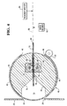
- a cross-sectional view of the shutter mechanism 40 looking in the direction of the arrows A, Fig.2, and showing also the slot 24 in the housing portion 20.
- the shutter mechanism 40 includes a hollow circular cylindrical shutter 42 which is rotatable about its axis and surrounds a fixed core 44.
- the shutter 42 is formed of a rigid material such as metal or plastics material and is provided with a substantially rectangular slot 46 which has a width sufficient to permit passage of a user card. Furthermore, the shutter 42 has an internal diameter sufficient to fully accommodate an inserted user card.
- the shutter 42 has a gear ring 48 attached thereto, which meshes with a drive gear 50 rotatable by a motor 52.
- the motor 52 can be controlled to impart a rotational movement, in the direction of the arrow 54 (Fig.3), to the shutter 42.
- the core 44 is provided with elongated recesses 56,58 within which are located respective rollers 60,62 mounted on respective shafts 64,66.
- the rollers 60,62 can be controlled when actuated, to drive a user card 70, which has been inserted into the card slot 24 by a user of the terminal 10, as will be explained hereinbelow.
- the core 44 is provided with a recess 72 having angled upper and lower faces 74,76 which define a slot 78 formed in the core 44, into which a user card 70 may be inserted.
- a user wishing to effect a transaction using the terminal 10 inserts a user card into the card slot 24.
- the card With the shutter 42 in the open position, as shown in Figs. 2 and 3, the card is inserted via the slot 46 in the shutter 42 into the slot 78 in the core 44.
- the card 70 is inserted by the user until its inner edge 80 approaches the inner surface of the shutter 42. Since as mentioned hereinabove, the length of the card 70 is less than the internal diameter of the cylindrical shutter 42, the card 70 is now positioned wholly within the shutter.
- a pair of microswitches located adjacent the inward boundary of the core 44, are actuated and, assuming that a magnetic presensor (not shown) located in front of the rollers 60,62, senses the presence of a magnetic stripe on the card 70, the motor 52 is caused to be effective to rotate the shutter 42 from the open position shown in Fig.3, in the direction of the arrow 54, to the closed position shown in Fig.4.
- a magnetic presensor located in front of the rollers 60,62
- the motor 52 is caused to be effective to rotate the shutter 42 from the open position shown in Fig.3, in the direction of the arrow 54, to the closed position shown in Fig.4.
- optical sensors may be utilized.
- the slot 46 is located diametrically opposite its original position, as shown in Fig.4.
- the shutter 42 is now in the closed position, and the user cannot access the card 70.
- a fraudulent user has inserted foreign material with the card, can such foreign material be accessed by the user.
- the rollers 60,62 are now operated to commence to drive the card 70 inwards through the slot 46 and along a feed path 90, see Fig.3 and 4. Further movement along the feed path 90 is effected under the control of drive means 92, which may include further drive rollers, or drive belts for example.
- the drive means 92 drives the card 70 to a location where a reader/writer unit 94 can read and/or write data from and/or onto the card 70 in accordance with the ATM transaction being effected.
- the card 70 is fed in a reverse direction, with the shutter 42 still in the position shown in Fig.4.
- the card 70 is fed in the reverse direction until the card is again located within the cylindrical shutter 42.
- a timer (not shown) is actuated and upon time-out of the timer, the shutter 42 is rotated in the direction of the arrow 54 through a further 180 degrees until the shutter is again positioned in the open position with the slot 46 directed towards the card entry slot 24.
- the time-out time of the timer is sufficient to allow for the outwardly moving card 70 to be positioned by the drive means 92 and drive rollers 60,62 wholly within the hollow cylindrical shutter 42, as shown in Fig.3.
- the user of the terminal 10 can now withdraw the card 70 manually.
- the shutter 42 is formed as a hollow circular cylindrical shell, other constructions are possible.
- the shutter could be in the form of a slatted belt.
- Fig.5 there is shown a cross-sectional view of a second embodiment of a shutter mechanism 100, which includes a shutter 102 in the form of a belt formed of slats 104 joined together in the manner of a slatted belt.
- the shutter 102 includes a slot 106 dimensioned to enable a user's card to pass therethrough, as in the first embodiment.
- the shutter 102 can be driven by drive means (not shown) to move round a solid core member 108 having recessed regions 110,112 in which are located drive rollers 114, 116 for moving an inserted card, as in the first embodiment.
- the core member 108 has a slot 109 dimensioned to receive a user card (not shown in Fig.5) inserted into the terminal 10.
- the operation of the second embodiment is generally similar to that of the first embodiment, such that the shutter 102 is either in the open position, as shown in Fig.5, with the hole 106 aligned with the card entry slot (not shown in Fig.5), or in the closed position, with the hole 106 at the diametrically opposed position, such that an inserted card (not shown in Fig.5) can be driven along a feed path to a reader/writer device (not shown in Fig.5).
- the shutter 102, Fig.5 is also of cylindrical shape, but the cross-section is not necessarily circular, as in the first embodiment, but aligns with the outer surface of the core 108, which has substantially flat upper and lower portions 120,122.
- a shutter mechanism including a shutter which in a first position enables card insertion or removal but prevents access by a user to the card reader/writer unit and in a second position prevents access by a user both to the card and to the card reader/writer.
- the shutter it is impossible for the shutter to be in a position wherein direct access to the card reader/writer is possible from the exterior of an ATM provided with the shutter mechanism.
Abstract
Description
- This invention relates to self-service terminals of the kind operable under the control of a user card to effect a transaction.
- Typically, such a terminal includes card handling apparatus having input means adapted to receive a card from a user of the apparatus, a card utilization device, card feeding means, control means adapted in operation to control the card feeding means to feed a received card inward from said input means to the utilization device and outward after utilization to a position wherein the card partially protrudes from said input means.
- An important application of such self-service terminals is in the field of automatic banking, where automated teller machines (ATMs) are in common use. Typically, in an ATM, a user insert a service card into the machine and then enters certain data (PIN number, quantity of currency, type of transaction etc) into a keyboard associated with the machine. The machine will then process the transaction, update the user's bank account if necessary and return the card to a partially protruding position from which it can be removed by user.
- In a known ATM, when a card is initially inserted in the machine's card entry slot, a sensor senses that the object being inserted is a correct card. For example, if the card must have a magnetic stripe thereon, a sensor can sense that such magnetic stripe is present and if so, cause a flat shutter member located behind the slot to be raised and permit further entry of the card along a feed path for engagement by feed rollers or other feed means which operate to feed the card fully into the machine and into a location for cooperation with a card processing means such as a magnetic reader/writer device, for example. A disadvantage of this known ATM is that it may be possible for a fraudulent person to enter foreign material at the same time as a magnetic stripe card and thereby jam the shutter open and obtain unauthorised direct access to the card reader/writer.
- It is an object of the present invention to provide a card operated self-service terminal wherein the possibility of unauthorised access to a card processing means within the terminal is reduced.
- Therefore, according to one aspect of the present invention, there is provided a self-service transaction terminal having a user card entry control shutter mechanism, characterized in that said shutter mechanism includes a hollow cylindrical shutter having a slot therein adapted to receive a user card inserted into said terminal, said hollow cylindrical shutter having a dimension such that an inserted card can be contained therewithin.
- According to another aspect of the present invention, there is provided a method for object entry control, characterized by the steps of: receiving an object inserted into an aperture in a hollow cylindrical shutter in an object entry control shutter mechanism; driving said shutter from a first position to receive said object to a second position; and feeding said object through said aperture towards an object processing means.
- Two embodiments of the present invention will now be described by way of example, with reference to the accompanying drawings, in which:-
- Fig.1 is a perspective view of an automated teller machine (ATM);
- Fig.2 is a front view of a first embodiment of a shutter mechanism for controlling the movement of a user card inserted into the ATM shown in Fig.1;
- Fig.3 is a cross-sectional view of the shutter mechanism shown in Fig.2, with an inserted user card in a first position;
- Fig.4 is a cross-sectional view of the shutter mechanism shown in Fig.2, with an inserted user card in a second position; and
- Fig.5 is a cross-sectional view of a second embodiment of a shutter mechanism for controlling the movement of a user card.
- Referring first to Fig.1, there is shown a perspective view of an automated teller machine (ATM) 10. The
ATM 10 has auser interface 12 which includes afirst housing portion 14 provided with akeyboard 16 having a plurality ofkeys 18. Asecond housing portion 20 is provided with adisplay 22, aslot 24 for receiving a user card, acash dispensing slot 26 and aprinter output slot 28 for issuing receipt slips or other printed items to the user. - Referring now to Fig.2, there is shown a front view of a
shutter mechanism 40 which is located behind thecard entry slot 24 in thehousing portion 20. Referring also to Fig.3, there is shown a cross-sectional view of theshutter mechanism 40 looking in the direction of the arrows A, Fig.2, and showing also theslot 24 in thehousing portion 20. Theshutter mechanism 40 includes a hollow circularcylindrical shutter 42 which is rotatable about its axis and surrounds afixed core 44. Theshutter 42 is formed of a rigid material such as metal or plastics material and is provided with a substantiallyrectangular slot 46 which has a width sufficient to permit passage of a user card. Furthermore, theshutter 42 has an internal diameter sufficient to fully accommodate an inserted user card. - The
shutter 42 has agear ring 48 attached thereto, which meshes with adrive gear 50 rotatable by amotor 52. Thus, themotor 52 can be controlled to impart a rotational movement, in the direction of the arrow 54 (Fig.3), to theshutter 42. - The
core 44 is provided withelongated recesses respective rollers respective shafts rollers user card 70, which has been inserted into thecard slot 24 by a user of theterminal 10, as will be explained hereinbelow. Thecore 44 is provided with arecess 72 having angled upper andlower faces slot 78 formed in thecore 44, into which auser card 70 may be inserted. - In operation, a user wishing to effect a transaction using the terminal 10 (Fig.1) inserts a user card into the
card slot 24. With theshutter 42 in the open position, as shown in Figs. 2 and 3, the card is inserted via theslot 46 in theshutter 42 into theslot 78 in thecore 44. Thecard 70 is inserted by the user until itsinner edge 80 approaches the inner surface of theshutter 42. Since as mentioned hereinabove, the length of thecard 70 is less than the internal diameter of thecylindrical shutter 42, thecard 70 is now positioned wholly within the shutter. - When the inserted
card 70 reaches the position shown in Fig.3, a pair of microswitches (not shown) located adjacent the inward boundary of thecore 44, are actuated and, assuming that a magnetic presensor (not shown) located in front of therollers card 70, themotor 52 is caused to be effective to rotate theshutter 42 from the open position shown in Fig.3, in the direction of thearrow 54, to the closed position shown in Fig.4. Instead of microswitches, optical sensors may be utilized. - Thus, the
slot 46 is located diametrically opposite its original position, as shown in Fig.4. Viewed by the user of theterminal 10, theshutter 42 is now in the closed position, and the user cannot access thecard 70. Nor, if a fraudulent user has inserted foreign material with the card, can such foreign material be accessed by the user. - The
rollers card 70 inwards through theslot 46 and along afeed path 90, see Fig.3 and 4. Further movement along thefeed path 90 is effected under the control ofdrive means 92, which may include further drive rollers, or drive belts for example. The drive means 92 drives thecard 70 to a location where a reader/writer unit 94 can read and/or write data from and/or onto thecard 70 in accordance with the ATM transaction being effected. - Following such read and/or write operation, the
card 70 is fed in a reverse direction, with theshutter 42 still in the position shown in Fig.4. Thecard 70 is fed in the reverse direction until the card is again located within thecylindrical shutter 42. When the leading edge of the outwardly movingcard 70 aligns with the above-mentioned microswitches (not shown) located at the inner region ofcore 44, a timer (not shown) is actuated and upon time-out of the timer, theshutter 42 is rotated in the direction of thearrow 54 through a further 180 degrees until the shutter is again positioned in the open position with theslot 46 directed towards thecard entry slot 24. The time-out time of the timer is sufficient to allow for the outwardly movingcard 70 to be positioned by the drive means 92 anddrive rollers cylindrical shutter 42, as shown in Fig.3. The user of theterminal 10 can now withdraw thecard 70 manually. - Although in the preferred embodiment described hereinabove, the
shutter 42 is formed as a hollow circular cylindrical shell, other constructions are possible. For example, the shutter could be in the form of a slatted belt. Referring to Fig.5, there is shown a cross-sectional view of a second embodiment of ashutter mechanism 100, which includes ashutter 102 in the form of a belt formed ofslats 104 joined together in the manner of a slatted belt. Theshutter 102 includes aslot 106 dimensioned to enable a user's card to pass therethrough, as in the first embodiment. Theshutter 102 can be driven by drive means (not shown) to move round asolid core member 108 having recessed regions 110,112 in which are locateddrive rollers core member 108 has aslot 109 dimensioned to receive a user card (not shown in Fig.5) inserted into theterminal 10. The operation of the second embodiment is generally similar to that of the first embodiment, such that theshutter 102 is either in the open position, as shown in Fig.5, with thehole 106 aligned with the card entry slot (not shown in Fig.5), or in the closed position, with thehole 106 at the diametrically opposed position, such that an inserted card (not shown in Fig.5) can be driven along a feed path to a reader/writer device (not shown in Fig.5). It will be appreciated that theshutter 102, Fig.5, is also of cylindrical shape, but the cross-section is not necessarily circular, as in the first embodiment, but aligns with the outer surface of thecore 108, which has substantially flat upper and lower portions 120,122. - Thus, there have been described embodiments of a shutter mechanism including a shutter which in a first position enables card insertion or removal but prevents access by a user to the card reader/writer unit and in a second position prevents access by a user both to the card and to the card reader/writer. Thus, it is impossible for the shutter to be in a position wherein direct access to the card reader/writer is possible from the exterior of an ATM provided with the shutter mechanism. It will be appreciated that, with the shutter in the open position, the user has access to the card, and can withdraw it if he or she wishes to do so, until the shutter has commenced to move to the closed position, that is, the user retains control of the card until shutter closure commences. Also, if the card cannot be read because it is jammed, or cannot be returned to the correct position within the hollow cylindrical shutter, the shutter will not be driven to the open position and the user will thus not be able to withdraw the card.
Claims (8)
- A self-service transaction terminal having a user card entry control shutter mechanism (40,100), characterized in that said shutter mechanism (40,100) includes a hollow cylindrical shutter having a slot (46,106) therein adapted to receive a user card (70) inserted into said terminal, said hollow cylindrical shutter (42,102) having a dimension such that an inserted card (70) can be contained therewithin.
- A self-service transaction terminal according to claim 1, characterized in that said shutter (42,102) is adapted to be driven from a first position wherein said slot (46,106) is located to receive a user card (70) inserted into said terminal, and a second, diametrically opposite position, wherein said slot (46,106) is located to permit feeding of said card (70) towards a card processing means (94).
- A self-service terminal according to claim 1 or claim 2, characterized in that said shutter (42,102) is arranged to move around a core member (44,108) having a slot (78,109) therein dimensioned to receive a user card (70).
- A self-service terminal according to claim 2 or claim 3, characterized by drive means (50) adapted to drive said shutter (42,102) from said first position to said second position in response to the insertion of said user card (70) into a location wherein said user card (70) is wholly contained within said hollow cylindrical shutter (42,102).
- A self-service terminal according to any one of claims 2 to 4, characterized by drive rollers (60,62; 114,116) located within said core member (44,108) and adapted to drive an inserted user card (70) along a feed path (90).
- A self-service terminal according to any one of the preceding claims, characterized in that said shutter (42) is of a hollow circular cylindrical shape, is formed of a rigid material, and is rotatable about its axis.
- A self-service terminal according to any one of claims 1 to 5, characterized in that said shutter (102) comprises a belt member formed of a plurality of slats (104).
- A method for object entry control, characterized by the steps of: receiving an object (70) inserted into an aperture (46,106) in a hollow cylindrical shutter in an object entry control shutter mechanism (40,100); driving said shutter from a first position to receive said object (70) to a second position; and feeding said object (70) through said aperture (46,106) towards an object processing means (94).
Applications Claiming Priority (2)
| Application Number | Priority Date | Filing Date | Title |
|---|---|---|---|
| GB9526335 | 1995-12-22 | ||
| GBGB9526335.6A GB9526335D0 (en) | 1995-12-22 | 1995-12-22 | Shutter mechanism for card controlled self-service transaction terminal |
Publications (3)
| Publication Number | Publication Date |
|---|---|
| EP0780814A2 true EP0780814A2 (en) | 1997-06-25 |
| EP0780814A3 EP0780814A3 (en) | 1998-08-12 |
| EP0780814B1 EP0780814B1 (en) | 2002-04-03 |
Family
ID=10785934
Family Applications (1)
| Application Number | Title | Priority Date | Filing Date |
|---|---|---|---|
| EP96309254A Expired - Lifetime EP0780814B1 (en) | 1995-12-22 | 1996-12-18 | Shutter mechanism for card controlled self-service transaction terminal |
Country Status (7)
| Country | Link |
|---|---|
| US (1) | US5760380A (en) |
| EP (1) | EP0780814B1 (en) |
| JP (1) | JP3844550B2 (en) |
| DE (1) | DE69620369T2 (en) |
| ES (1) | ES2175044T3 (en) |
| GB (1) | GB9526335D0 (en) |
| ZA (1) | ZA9610818B (en) |
Cited By (11)
| Publication number | Priority date | Publication date | Assignee | Title |
|---|---|---|---|---|
| EP0965944A2 (en) * | 1998-06-19 | 1999-12-22 | Systems AG | Device for operating memorised data on a data carrier,in particularly prepaid cards |
| EP1017013A2 (en) * | 1998-12-11 | 2000-07-05 | Mannesmann VDO Aktiengesellschaft | Locking mechanism for a data card read/write apparatus |
| GB2351587A (en) * | 1999-06-29 | 2001-01-03 | Ncr Int Inc | Fraud protection for a self-service terminal |
| EP1093092A2 (en) * | 1999-10-11 | 2001-04-18 | Wincor Nixdorf GmbH & Co KG | ATM with display-shutter |
| US6494364B2 (en) | 2000-03-28 | 2002-12-17 | Ncr Corporation | Self-service terminal |
| EP1505549A1 (en) * | 2003-08-06 | 2005-02-09 | Wincor Nixdorf International GmbH | Self service device with an apparatus for surveillance |
| EP1798668A1 (en) * | 2005-12-13 | 2007-06-20 | Hitachi-Omron Terminal Solutions, Corp. | Card processor |
| WO2008095757A1 (en) * | 2007-02-03 | 2008-08-14 | Wincor Nixdorf International Gmbh | Self-service appliance |
| EP1995943A3 (en) * | 2000-08-02 | 2009-02-18 | Dai Nippon Printing Co., Ltd. | Image printing system |
| EP2816507A1 (en) * | 2013-06-21 | 2014-12-24 | ddm hopt + schuler GmbH & Co. KG. | Card reader with two drums which are mounted so that they can be rotated within each other |
| EP3048592A4 (en) * | 2013-09-16 | 2016-11-02 | Grg Banking Equipment Co Ltd | Method, device, and self service equipment thereof for card processing in card reader |
Families Citing this family (18)
| Publication number | Priority date | Publication date | Assignee | Title |
|---|---|---|---|---|
| US7240827B2 (en) * | 2002-11-26 | 2007-07-10 | Diebold, Incorporated | Automated banking machine with improved resistance to fraud |
| GB2363890A (en) * | 2000-06-24 | 2002-01-09 | Ncr Int Inc | Self service terminal with a media entry aperture of variable size |
| JP4226227B2 (en) * | 2001-03-07 | 2009-02-18 | 三菱電機株式会社 | Card module shutter mechanism |
| JP4779224B2 (en) * | 2001-04-20 | 2011-09-28 | パナソニック株式会社 | Recording medium attaching / detaching device |
| CN101410879B (en) * | 2003-03-10 | 2011-04-06 | 迪布尔特有限公司 | Cash dispensing automated banking machine with improved card retention capabilities and method |
| US6997376B1 (en) * | 2003-10-17 | 2006-02-14 | Rowe International Corporation | Anti-tether device |
| KR100987838B1 (en) | 2003-12-31 | 2010-10-13 | 노틸러스효성 주식회사 | shutter locker in auto teller machine |
| US7810734B2 (en) * | 2004-05-05 | 2010-10-12 | Utc Fire & Security Corporation | Anti-skimming card reader surface configuration |
| US8418917B1 (en) * | 2005-12-20 | 2013-04-16 | Diebold Self-Service Systems | Banking machine controlled responsive to data read from data bearing records |
| US9038891B2 (en) * | 2005-12-20 | 2015-05-26 | Diebold Self-Service Systems Division Of Diebold, Incorporated | Banking machine controlled responsive to data read from data bearing records |
| JP5008997B2 (en) * | 2007-02-05 | 2012-08-22 | 日立オムロンターミナルソリューションズ株式会社 | Recording medium receiving apparatus and conveying method |
| CN101840595B (en) | 2009-11-06 | 2012-05-16 | 广州广电运通金融电子股份有限公司 | Financial self-service equipment for preventing foreign substance blockage and sticky destruction |
| JP5180984B2 (en) * | 2010-03-16 | 2013-04-10 | 日立オムロンターミナルソリューションズ株式会社 | Magnetic reader |
| CN103824391B (en) * | 2014-02-26 | 2017-10-31 | 广州广电运通金融电子股份有限公司 | Self-aided terminal is anti-to exchange chucking method and device |
| EP3009962A1 (en) * | 2014-10-13 | 2016-04-20 | Corim S.r.l. | Safety device for a port of entry of an automatic machine |
| JP6554902B2 (en) * | 2015-05-12 | 2019-08-07 | 沖電気工業株式会社 | Medium information reading apparatus and medium transaction apparatus |
| US10049532B1 (en) | 2018-04-26 | 2018-08-14 | Capital One Services, Llc | Automated teller machine (ATM) device with sealed slot |
| JP2022186325A (en) * | 2021-06-04 | 2022-12-15 | 日立チャネルソリューションズ株式会社 | Card reader and foreign object detection method for card reader |
Family Cites Families (4)
| Publication number | Priority date | Publication date | Assignee | Title |
|---|---|---|---|---|
| US3671719A (en) * | 1971-04-19 | 1972-06-20 | Ibm | Roller structure for card reader |
| FR2295503A1 (en) * | 1974-12-20 | 1976-07-16 | Cit Alcatel | BLOCKING DEVICE FOR CARD READERS OR BADGES FOR PUBLIC USE |
| GB2005533B (en) * | 1977-07-20 | 1982-01-13 | Dougal J | Security transfer device |
| DE4318333A1 (en) * | 1993-06-02 | 1994-12-08 | Siemens Ag | Card reader |
-
1995
- 1995-12-22 GB GBGB9526335.6A patent/GB9526335D0/en active Pending
-
1996
- 1996-06-14 US US08/664,950 patent/US5760380A/en not_active Expired - Lifetime
- 1996-12-18 ES ES96309254T patent/ES2175044T3/en not_active Expired - Lifetime
- 1996-12-18 EP EP96309254A patent/EP0780814B1/en not_active Expired - Lifetime
- 1996-12-18 DE DE69620369T patent/DE69620369T2/en not_active Expired - Lifetime
- 1996-12-20 ZA ZA9610818A patent/ZA9610818B/en unknown
- 1996-12-24 JP JP34328996A patent/JP3844550B2/en not_active Expired - Fee Related
Non-Patent Citations (1)
| Title |
|---|
| None |
Cited By (15)
| Publication number | Priority date | Publication date | Assignee | Title |
|---|---|---|---|---|
| EP0965944A2 (en) * | 1998-06-19 | 1999-12-22 | Systems AG | Device for operating memorised data on a data carrier,in particularly prepaid cards |
| EP0965944A3 (en) * | 1998-06-19 | 2000-08-30 | Systems AG | Device for operating memorised data on a data carrier,in particularly prepaid cards |
| EP1017013A2 (en) * | 1998-12-11 | 2000-07-05 | Mannesmann VDO Aktiengesellschaft | Locking mechanism for a data card read/write apparatus |
| EP1017013A3 (en) * | 1998-12-11 | 2002-12-18 | Siemens Aktiengesellschaft | Locking mechanism for a data card read/write apparatus |
| GB2351587A (en) * | 1999-06-29 | 2001-01-03 | Ncr Int Inc | Fraud protection for a self-service terminal |
| US6357657B1 (en) | 1999-06-29 | 2002-03-19 | Ncr Corporation | Anti-fraud device |
| EP1093092A3 (en) * | 1999-10-11 | 2002-10-02 | Wincor Nixdorf GmbH & Co KG | ATM with display-shutter |
| EP1093092A2 (en) * | 1999-10-11 | 2001-04-18 | Wincor Nixdorf GmbH & Co KG | ATM with display-shutter |
| US6494364B2 (en) | 2000-03-28 | 2002-12-17 | Ncr Corporation | Self-service terminal |
| EP1995943A3 (en) * | 2000-08-02 | 2009-02-18 | Dai Nippon Printing Co., Ltd. | Image printing system |
| EP1505549A1 (en) * | 2003-08-06 | 2005-02-09 | Wincor Nixdorf International GmbH | Self service device with an apparatus for surveillance |
| EP1798668A1 (en) * | 2005-12-13 | 2007-06-20 | Hitachi-Omron Terminal Solutions, Corp. | Card processor |
| WO2008095757A1 (en) * | 2007-02-03 | 2008-08-14 | Wincor Nixdorf International Gmbh | Self-service appliance |
| EP2816507A1 (en) * | 2013-06-21 | 2014-12-24 | ddm hopt + schuler GmbH & Co. KG. | Card reader with two drums which are mounted so that they can be rotated within each other |
| EP3048592A4 (en) * | 2013-09-16 | 2016-11-02 | Grg Banking Equipment Co Ltd | Method, device, and self service equipment thereof for card processing in card reader |
Also Published As
| Publication number | Publication date |
|---|---|
| EP0780814A3 (en) | 1998-08-12 |
| GB9526335D0 (en) | 1996-02-21 |
| JPH09223265A (en) | 1997-08-26 |
| JP3844550B2 (en) | 2006-11-15 |
| DE69620369D1 (en) | 2002-05-08 |
| US5760380A (en) | 1998-06-02 |
| ES2175044T3 (en) | 2002-11-16 |
| EP0780814B1 (en) | 2002-04-03 |
| DE69620369T2 (en) | 2002-11-14 |
| ZA9610818B (en) | 1997-06-24 |
Similar Documents
| Publication | Publication Date | Title |
|---|---|---|
| US5760380A (en) | Shutter mechanism for card controlled self-service transaction terminal | |
| US5929413A (en) | Self-service terminal (SST) and method of operating the SST to control movement of a card of the SST | |
| RU2232423C2 (en) | Automation to implement transactions with testing of transfer channel | |
| RU2224284C2 (en) | Transaction machine | |
| US5540425A (en) | Article depositing apparatus | |
| US5577719A (en) | Document alignment system | |
| PL195616B1 (en) | Media storage and recycling system for automated banking machine | |
| CN100572243C (en) | Bank not deposit and withdraw device | |
| US5683079A (en) | Document processing apparatus | |
| US5294785A (en) | Cards processor | |
| EP0329034A1 (en) | Bill handler | |
| EP0419108A2 (en) | An apparatus for selectively conveying a paper money and a magnetic card | |
| US5929426A (en) | Magnetic card sensor for sensing presence of a card having a magnetic stripe and thickness complying with ISO standard | |
| JP4017052B2 (en) | Vending machines that can use IC cards | |
| JP2908525B2 (en) | Bill / card identification device | |
| JPH0778279A (en) | Automatic teller machine | |
| KR200374271Y1 (en) | Dual shutter structure of an auto teller machine | |
| JP2753050B2 (en) | Booklet pagination device | |
| CA2414424A1 (en) | Metal bezel for validator | |
| JP4530150B2 (en) | Card-like medium handling device | |
| KR920004421B1 (en) | Automatic transaction system | |
| EP1752404B1 (en) | Media storage and recycling system for automated banking machine | |
| KR100609793B1 (en) | Paper sheets treatment device | |
| JP4186033B2 (en) | Magnetic card and IC card processing method in handling device for plural types of memory cards | |
| JPS62274391A (en) | Currency withdrawing apparatus |
Legal Events
| Date | Code | Title | Description |
|---|---|---|---|
| PUAI | Public reference made under article 153(3) epc to a published international application that has entered the european phase |
Free format text: ORIGINAL CODE: 0009012 |
|
| AK | Designated contracting states |
Kind code of ref document: A2 Designated state(s): DE ES FR GB IT |
|
| PUAL | Search report despatched |
Free format text: ORIGINAL CODE: 0009013 |
|
| AK | Designated contracting states |
Kind code of ref document: A3 Designated state(s): DE ES FR GB IT |
|
| 17P | Request for examination filed |
Effective date: 19990212 |
|
| 17Q | First examination report despatched |
Effective date: 20000905 |
|
| GRAG | Despatch of communication of intention to grant |
Free format text: ORIGINAL CODE: EPIDOS AGRA |
|
| GRAG | Despatch of communication of intention to grant |
Free format text: ORIGINAL CODE: EPIDOS AGRA |
|
| GRAH | Despatch of communication of intention to grant a patent |
Free format text: ORIGINAL CODE: EPIDOS IGRA |
|
| REG | Reference to a national code |
Ref country code: GB Ref legal event code: IF02 |
|
| GRAH | Despatch of communication of intention to grant a patent |
Free format text: ORIGINAL CODE: EPIDOS IGRA |
|
| GRAA | (expected) grant |
Free format text: ORIGINAL CODE: 0009210 |
|
| AK | Designated contracting states |
Kind code of ref document: B1 Designated state(s): DE ES FR GB IT |
|
| REF | Corresponds to: |
Ref document number: 69620369 Country of ref document: DE Date of ref document: 20020508 |
|
| ET | Fr: translation filed | ||
| REG | Reference to a national code |
Ref country code: ES Ref legal event code: FG2A Ref document number: 2175044 Country of ref document: ES Kind code of ref document: T3 |
|
| PLBE | No opposition filed within time limit |
Free format text: ORIGINAL CODE: 0009261 |
|
| STAA | Information on the status of an ep patent application or granted ep patent |
Free format text: STATUS: NO OPPOSITION FILED WITHIN TIME LIMIT |
|
| 26N | No opposition filed |
Effective date: 20030106 |
|
| REG | Reference to a national code |
Ref country code: GB Ref legal event code: 746 Effective date: 20091111 |
|
| PGFP | Annual fee paid to national office [announced via postgrant information from national office to epo] |
Ref country code: GB Payment date: 20101118 Year of fee payment: 15 |
|
| PGFP | Annual fee paid to national office [announced via postgrant information from national office to epo] |
Ref country code: DE Payment date: 20101111 Year of fee payment: 15 |
|
| PGFP | Annual fee paid to national office [announced via postgrant information from national office to epo] |
Ref country code: IT Payment date: 20101129 Year of fee payment: 15 |
|
| PGFP | Annual fee paid to national office [announced via postgrant information from national office to epo] |
Ref country code: ES Payment date: 20111031 Year of fee payment: 16 Ref country code: FR Payment date: 20111014 Year of fee payment: 16 |
|
| GBPC | Gb: european patent ceased through non-payment of renewal fee |
Effective date: 20121218 |
|
| REG | Reference to a national code |
Ref country code: FR Ref legal event code: ST Effective date: 20130830 |
|
| REG | Reference to a national code |
Ref country code: DE Ref legal event code: R119 Ref document number: 69620369 Country of ref document: DE Effective date: 20130702 |
|
| PG25 | Lapsed in a contracting state [announced via postgrant information from national office to epo] |
Ref country code: DE Free format text: LAPSE BECAUSE OF NON-PAYMENT OF DUE FEES Effective date: 20130702 |
|
| PG25 | Lapsed in a contracting state [announced via postgrant information from national office to epo] |
Ref country code: FR Free format text: LAPSE BECAUSE OF NON-PAYMENT OF DUE FEES Effective date: 20130102 Ref country code: GB Free format text: LAPSE BECAUSE OF NON-PAYMENT OF DUE FEES Effective date: 20121218 |
|
| PG25 | Lapsed in a contracting state [announced via postgrant information from national office to epo] |
Ref country code: IT Free format text: LAPSE BECAUSE OF NON-PAYMENT OF DUE FEES Effective date: 20121218 |
|
| REG | Reference to a national code |
Ref country code: ES Ref legal event code: FD2A Effective date: 20140306 |
|
| PG25 | Lapsed in a contracting state [announced via postgrant information from national office to epo] |
Ref country code: ES Free format text: LAPSE BECAUSE OF NON-PAYMENT OF DUE FEES Effective date: 20121219 |