EP1798396A1 - Internal combustion engine - Google Patents
Internal combustion engine Download PDFInfo
- Publication number
- EP1798396A1 EP1798396A1 EP06126207A EP06126207A EP1798396A1 EP 1798396 A1 EP1798396 A1 EP 1798396A1 EP 06126207 A EP06126207 A EP 06126207A EP 06126207 A EP06126207 A EP 06126207A EP 1798396 A1 EP1798396 A1 EP 1798396A1
- Authority
- EP
- European Patent Office
- Prior art keywords
- crankshaft
- engine
- piston
- bearings
- cylinders
- Prior art date
- Legal status (The legal status is an assumption and is not a legal conclusion. Google has not performed a legal analysis and makes no representation as to the accuracy of the status listed.)
- Granted
Links
Images




Classifications
-
- F—MECHANICAL ENGINEERING; LIGHTING; HEATING; WEAPONS; BLASTING
- F02—COMBUSTION ENGINES; HOT-GAS OR COMBUSTION-PRODUCT ENGINE PLANTS
- F02B—INTERNAL-COMBUSTION PISTON ENGINES; COMBUSTION ENGINES IN GENERAL
- F02B75/00—Other engines
- F02B75/32—Engines characterised by connections between pistons and main shafts and not specific to preceding main groups
-
- F—MECHANICAL ENGINEERING; LIGHTING; HEATING; WEAPONS; BLASTING
- F02—COMBUSTION ENGINES; HOT-GAS OR COMBUSTION-PRODUCT ENGINE PLANTS
- F02B—INTERNAL-COMBUSTION PISTON ENGINES; COMBUSTION ENGINES IN GENERAL
- F02B75/00—Other engines
- F02B75/04—Engines with variable distances between pistons at top dead-centre positions and cylinder heads
- F02B75/048—Engines with variable distances between pistons at top dead-centre positions and cylinder heads by means of a variable crank stroke length
-
- Y—GENERAL TAGGING OF NEW TECHNOLOGICAL DEVELOPMENTS; GENERAL TAGGING OF CROSS-SECTIONAL TECHNOLOGIES SPANNING OVER SEVERAL SECTIONS OF THE IPC; TECHNICAL SUBJECTS COVERED BY FORMER USPC CROSS-REFERENCE ART COLLECTIONS [XRACs] AND DIGESTS
- Y10—TECHNICAL SUBJECTS COVERED BY FORMER USPC
- Y10T—TECHNICAL SUBJECTS COVERED BY FORMER US CLASSIFICATION
- Y10T74/00—Machine element or mechanism
- Y10T74/21—Elements
- Y10T74/2173—Cranks and wrist pins
- Y10T74/2174—Multiple throw
Definitions
- the bearing force applied to each crankshaft bearing varies depending on the design parameters of the internal combustion engine.
- the design parameters may, for example, include the magnitude of the maximum internal pressure of the cylinders, the maximum revolving speed, and the mass of the moving elements. If the internal combustion engine is to be used in a vehicle, the following differences may occur between a single-link engine and a multilink engine. According to the single-link engine in Figures 8A to 8E, the maximum values of the bearing force received by the second and fourth crankshaft bearings 11b, 11d counted from the front of the engine are about the same as or smaller than the maximum value of the bearing force received by the third crankshaft bearing 11c counted from the front of the engine.
- Figures 8A to 8E and Figures 9A to 9E one of the points at which the second crankshaft bearing 11b receives a maximum force is at the point of combustion for the first cylinder (i.e. near the top dead center for compression).
- Figures 10 and 11 illustrate crank throws of the crankshaft 4 for the first and second cylinders at this timing position, and show what kind of forces are acting on the crankshaft 4 and are transmitted to the cylinder block 12 at the combustion timing of the first cylinder.
- Figure 10 corresponds to the single-link engine
- Figure 11 corresponds to the multilink engine.
- the middle journal 4A is supported by the second crankshaft bearing 11b.
- the highly-rigid bearings 11b, 11d therefore have a higher rigidity than the remaining crankshaft bearings 11a, 11c, 11e. Consequently, the bearing strength of the highly-rigid bearings 11b, 11d is increased and the force acting on the highly-rigid bearings 11b, 11d is substantially reduced which thereby reduces uneven forces acting on the crankshaft bearings 11a to 11e. In other words, the forces acting on the crankshaft bearings 11a to 11e are uniformized.
- Figure 3 illustrates a second embodiment of the present invention, and is a sectional view of the highly-rigid bearings 11b, 11d included in the multilink-type internal combustion engine.
- Components shown in Figure 3 that are the same as those in Figure 13 are given the same reference numerals, but Figure 3 is different from Figure 13 in that the highly-rigid bearings 11b, 11d each have a housing 24 of the variable-compression-ratio actuator 31 fastened thereto.
- the variable-compression-ratio actuator 31 has a feed screw and a rod within the housing 24.
- an upward inertia force C near the top dead center of each piston is set lower than a downward inertia force D near the bottom dead center thereof (see Figure 12) in order to reduce secondary vibration occurring during operation.
- a maximum downward acceleration value of each piston is set lower than a maximum upward acceleration value thereof.
- the highly-rigid bearings 11b, 11d are given locally higher rigidity in the vertical direction of the pistons, which is the direction in which a maximum force is exerted. Accordingly, the rigidity of the highly-rigid bearings 11b, 11d is effectively increased but an increase in weight and size resulting from unnecessarily increasing the rigidity in other directions is prevented.
Landscapes
- Engineering & Computer Science (AREA)
- Chemical & Material Sciences (AREA)
- Combustion & Propulsion (AREA)
- Mechanical Engineering (AREA)
- General Engineering & Computer Science (AREA)
- Shafts, Cranks, Connecting Bars, And Related Bearings (AREA)
- Output Control And Ontrol Of Special Type Engine (AREA)
- Cylinder Crankcases Of Internal Combustion Engines (AREA)
Abstract
Description
- The present invention relates to an internal combustion engine and particularly, but not exclusively, to a multi-cylinder internal combustion engine having a plurality of cylinders arranged in an array. Embodiments of the invention relate to an improved crankshaft bearing structure suitable for an internal combustion engine equipped with a multilink-type piston-crank mechanism.
-
Japanese Unexamined Patent Application Publication No. 2002-61501 - A new problem has been found in a multilink-type piston-crank mechanism of this type. In detail, when the piston-stroke characteristics change, an excessive force acts on specific crankshaft bearings as a result of inertia force exerted on the crank bearings from crank rotating systems, thus making it difficult to attain sufficient bearing strength.
- It is an aim of the invention to address this problem and to improve upon known technology. Other aims and advantages of the invention will become apparent from the following description, claims and drawings.
- Aspects of the invention therefore provide an engine and a vehicle as claimed in the appended claims.
- According to another aspect of the invention there is provided a crankshaft bearing structure in an internal combustion engine comprising a cylinder block having a plurality of cylinders arranged in a cylinder-arrangement direction, each cylinder having a piston fitted therein in a vertically movable fashion, a crankshaft which is disposed below the plurality of cylinders and extends in the cylinder-arrangement direction, the crankshaft including a plurality of journals rotatably supported by the cylinder block by means of a plurality of crankshaft bearings and a plurality of crankpins disposed between adjacent pairs of the journals and a piston-crank mechanism that links the crankpins with piston pins of the pistons, wherein at least one of the crankshaft bearings that receives a force greater than a force produced in response to a maximum combustion pressure by one of the cylinders comprises a highly-rigid bearing having a rigidity higher than that of the remaining crankshaft bearings.
- According to another aspect of the invention there is provided an internal combustion engine comprising a cylinder block having a plurality of cylinders arranged in a cylinder-arrangement direction, each cylinder having a piston fitted therein in a vertically movable fashion, a crankshaft which is disposed below the plurality of cylinders and extends in the cylinder-arrangement direction, the crankshaft including a plurality of journals rotatably supported by the cylinder block by means of a plurality of crankshaft bearings and a plurality of crankpins disposed between adjacent pairs of the journals and a piston-crank mechanism that links the crankpins with piston pins of the pistons, wherein the piston-crank mechanism allows an upward inertia force near a top dead center of each piston to be set smaller than a downward inertia force near a bottom dead center of the piston and wherein, of the plurality of crankshaft bearings, at least one crankshaft bearing disposed between an adjacent pair of the cylinders, having a relationship in which the piston in one of the cylinders is near the top dead center when the piston in the other cylinder is near the bottom dead center, comprises a highly-rigid bearing having a rigidity higher than that of the remaining crankshaft bearings.
- According to a further aspect of the invention there is provided an internal combustion engine comprising a cylinder block having a plurality of cylinders arranged in a cylinder-arrangement direction, each cylinder having a piston fitted therein in a vertically movable fashion, a crankshaft which is disposed below the plurality of cylinders and extends in the cylinder-arrangement direction, the crankshaft including a plurality of journals rotatably supported by the cylinder block by means of a plurality of crankshaft bearings and a plurality of crankpins disposed between adjacent pairs of the journals and a piston-crank mechanism that links the crankpins with piston pins of the pistons, wherein at least one of the crankshaft bearings that is disposed between an adjacent pair of the cylinders, having a relationship in which an upward inertia force of one of the cylinders is smaller than a downward inertia force of the other cylinder during combustion of said one of the cylinders, comprises a highly-rigid bearing having a rigidity higher than that of the remaining crankshaft bearings.
- In an embodiment, the engine comprises compression-ratio changing means for changing a compression ratio of the engine, wherein the compression-ratio changing means comprises a control shaft rotatably supported by the cylinder block, control cams disposed eccentrically to the control shaft and attached to the first ends of the control links, and a variable-compression-ratio actuator for changing or maintaining a rotation angle of the control shaft, wherein the compression-ratio changing means is arranged to change the compression ratio of the engine by altering the position of each rocking fulcrum in order to change the position of the top dead center of the corresponding piston, and wherein the variable-compression-ratio actuator has a housing that is fixed to said at least one crankshaft bearing having higher rigidity than the remaining crankshaft bearings.
- The engine may comprise a plurality of film-like bulkheads integrally provided in the cylinder block; and a ladder frame fixed to lower surfaces of the bulkheads, wherein the ladder frame comprises a plurality of first bearing caps that rotatably support the journals of the crankshaft together with the bulkheads, and second bearing caps fixed to a lower surface of the ladder frame and rotatably supporting the control shaft together with the ladder frame, and wherein the variable-compression-ratio actuator has a housing that is fixed to at least one of the second bearing caps that is positioned below said at least one crankshaft bearing having higher rigidity.
- In an embodiment, the engine comprises a plurality of film-like bulkheads integrally provided in the cylinder block; and a ladder frame fixed to lower surfaces of the bulkheads, wherein the ladder frame has a plurality of first bearing caps that rotatably support the journals of the crankshaft together with the bulkheads, and second bearing caps fixed to a lower surface of the ladder frame and rotatably supporting the control shaft together with the ladder frame, the control shaft being disposed obliquely below the crankshaft, and wherein at least one of the second bearing caps that is positioned below said at least one crankshaft bearing having higher rigidity is longer in a width direction of the engine than the remaining second bearing caps.
- The engine may comprise at least two fastening bolts disposed on opposite sides of each journal of the crankshaft, said at least two fastening bolts being used for fastening the ladder frame and said at least one of the second bearing caps that is longer in the width direction of the engine than the remaining second bearing caps together to the corresponding bulkhead.
- In an embodiment, the plurality of cylinders comprises four cylinders arranged in a front-back direction of the internal combustion engine, and the plurality of crankshaft bearings comprises five crankshaft bearings arranged in the front-back direction, and wherein said remaining crankshaft bearings having a through hole in their side surfaces comprise the first and third bulkheads from the front of the engine.
- According to a still further aspect of the invention there is provided an internal combustion engine comprising a cylinder block having a plurality of cylinders therein, each cylinder containing a piston, each piston being slidable between a top dead center and a bottom dead center within the corresponding one of the cylinders, a crankshaft which is disposed below the plurality of cylinders and extends in a direction in which the cylinders are arranged, the crankshaft including a plurality of journals and a plurality of crankshaft bearings rotatably supporting the crankshaft, wherein the crankshaft is provided with a piston-crank mechanism that links the crankshaft and the pistons by means of a plurality of crankpins disposed between adjacent pairs of the journals and piston pins provided for the pistons, the piston-crank mechanism being arranged to allow an upward inertia force produced near the top dead center of each piston to be smaller than a downward inertia force produced near the bottom dead center of the piston and wherein at least one of the plurality of crankshaft bearings that is disposed between an adjacent pair of the cylinders, the pair of cylinders having a relationship in which an upward inertia force of one of the adjacent cylinders is smaller than a downward inertia force of the other cylinder during combustion of said one of the adjacent cylinders, has a rigidity higher than that of the remaining crankshaft bearings.
- According to yet another aspect of the invention there is provided an internal combustion engine comprising a cylinder block having a plurality of cylinders therein, each cylinder containing a piston, each piston being slidable between a top dead center and a bottom dead center within its corresponding cylinder, a crankshaft which is disposed below the plurality of cylinders and extends in a direction in which the cylinders are arranged, the crankshaft being rotatably supported by a plurality of crankshaft bearings provided in the cylinder block, the crankshaft including a plurality of journals rotatably supported by the crankshaft bearings and a plurality of crankpins disposed between adjacent pairs of the journals and a piston-crank mechanism that links the crankpins with piston pins of the pistons, wherein at least one of the plurality of crankshaft bearings that receives a force greater than a force produced in response to a maximum combustion pressure by a predetermined one of the cylinders has a rigidity higher than that of the remaining crankshaft bearings.
- For example, an internal combustion engine in accordance with an embodiment includes a cylinder block having a plurality of cylinders therein, each cylinder containing a piston in a vertically slidable fashion; a crankshaft which is disposed below the plurality of cylinders and extends in a direction in which the cylinders are arranged, the crankshaft being rotatably supported by a plurality of crankshaft bearings provided in the cylinder block, the crankshaft including a plurality of journals rotatably supported by the crankshaft bearings and a plurality of crankpins disposed between adjacent pairs of the journals; and a piston-crank mechanism that links the crankpins with piston pins of the pistons. The piston-crank mechanism allows an upward inertia force produced near a top dead center of each piston to be smaller than a downward inertia force produced near a bottom dead center of the piston. Of the plurality of crankshaft bearings, at least one crankshaft bearing disposed between an adjacent pair of the cylinders, having a relationship in which the piston in one of the adjacent cylinders is near the top dead center when the piston in the other cylinder is near the bottom dead center, has a rigidity higher than that of the remaining crankshaft bearings.
- According to the present invention, of the plurality of crankshaft bearings, the rigidity of at least one crankshaft bearing is set higher than that of the remaining crankshaft bearings, thereby achieving proper distribution of force exerted on the crankshaft bearings.
- Within the scope of this application it is envisaged that the various aspects, embodiments, examples and alternatives set out in the preceding paragraphs, in the claims and in the following description may be taken individually or in any combination thereof.
- The present invention will now be described, by way of example only, with reference to the accompanying drawings in which:
- Figure 1 shows a cross-sectional view of an inline four-cylinder multilink-type internal combustion engine according to a first embodiment of the present invention;
- Figure 2 illustrates forces acting on first and second cylinders in the first embodiment;
- Figure 3 shows a vertical sectional view of a crankshaft bearing structure in an internal combustion engine according to a second embodiment of the present invention;
- Figure 4 shows a vertical sectional view of a crankshaft bearing structure in an internal combustion engine according to a third embodiment of the present invention;
- Figure 5 shows a vertical sectional view of a crankshaft bearing structure in an internal combustion engine according to a fourth embodiment of the present invention;
- Figure 6 illustrates a multilink-type piston-crank mechanism according to a comparative example to the present invention;
- Figure 7 is a sectional view taken along line VII-VII in Figure 6;
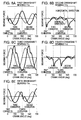
- Figures 8A to 8E illustrate forces acting on crankshaft bearings included in an inline four-cylinder internal combustion engine equipped with a single-link-type piston-crank mechanism;
- Figures 9A to 9E illustrate forces acting on crankshaft bearings included in an inline four-cylinder internal combustion engine equipped with a multilink-type piston-crank mechanism according to the comparative example;
- Figure 10 illustrates forces acting on a crankshaft in first and second cylinders of the single-link engine shown in Figures 8A to 8E;
- Figure 11 illustrates forces acting on a crankshaft in first and second cylinders of the multilink engine shown in Figures 9A to 9E;
- Figure 12 is a characteristic diagram illustrating fluctuations in inertia force of one cylinder with respect to a crank angle in the single-link engine and the multilink engine; and
- Figure 13 is a vertical sectional view of a crankshaft bearing structure in an internal combustion engine.
- Embodiments of the present invention are described below with reference to the drawings. In the following description, the term "up" refers to the direction in which a piston moves towards its top dead center position (the similar terms "upward" or "upper" are to be construed in a similar manner) and the term "down" refers to the direction in which a piston moves towards its bottom dead centre position (the similar terms "downward", bottom" and "lower" are to be construed in a similar manner). The term "front-back direction" refers to the direction from the front to the back of an engine or the direction in which cylinders are arranged.
- Generally, a cylinder block for a vehicle is made of a solid casting, and comprises a cylinder portion having a plurality of cylinders (i.e. cylinder bores) and a crankcase portion. The plurality of cylinders in the cylinder portion are arranged in the front-back direction of the engine (Note: the arrangement of the cylinders may alternatively be referred to as the cylinder-arrangement direction), and the crankcase portion covers a crankshaft that extends below the cylinder portion in the cylinder-arrangement direction and connecting rods connected to crankpins of the crankshaft.
- The crankshaft has journals which are rotatably supported by the cylinder block by means of crankshaft bearings. Each of the crankshaft bearings includes a partition- or film-like bulkhead that extends downward between adjacent cylinders from the lower end of the cylinder portion towards the inside of the crankcase portion, and a bearing cap that is fixed to the lower surface of the bulkhead while holding the corresponding journal of the crankshaft from opposite sides. The lower surface of each bulkhead and the upper surface of each bearing cap both have semicircular notches for rotatably supporting the corresponding journal of the crankshaft. Generally, each of the bulkheads is integrated with the cylinder block and has its opposite sides integrally joined to inner walls of the crankcase portion.
- In an inline four-cylinder internal combustion engine, the first to fourth cylinders are arranged in that order from the front of the engine in the front-back direction of the engine. A total of five crankshaft bearings (constituted by the bulkheads and the bearing caps) are provided, three of which are disposed between adjacent cylinders, one of which is in front of the first cylinder (which is the frontmost cylinder of the engine), and one of which is behind the fourth cylinder (which is the rearmost cylinder of the engine). The five crankshaft bearings will be referred to as first to fifth crankshaft bearings in that order from the front of the engine. The thickness of the first to fifth crankshaft bearings, that is, the dimension thereof in the front-back direction of the engine, may be set such that the first and fifth crankshaft bearings at the front and back sides of the internal combustion engine are thinner than the remaining second to fourth intermediate crankshaft bearings. In that case, the three remaining second to fourth crankshaft bearings disposed between adjacent cylinders generally have the same dimension.
- Figure 6 is a sectional view of an internal combustion engine equipped with a multilink-type piston-crank mechanism according to a comparative example. Figure 7 is a sectional view taken along line VII-VII in Figure 6. In Figure 7, the front side of the internal combustion engine is on the left hand side of the Figure, and the cylinders are referred to as first to fourth cylinders in that order from left to right across the Figure (i.e. from the front to the back of the engine). The basic structure and effects of a multilink-type piston-crank mechanism (hereinafter referred to as a "multilink mechanism") are discussed in the aforementioned
Japanese Unexamined Patent Application Publication No. 2002-61501 upper links 3 coupled topiston pins 2 ofpistons 1,lower links 6 coupled to theupper links 3 and tocrankpins 5 of acrankshaft 4, andcontrol links 8 whose first ends are rockably supported by acylinder block 12 about rocking fulcrums thereof and whose second ends are coupled to thelower links 6 so as to restrict the movement of thelower links 6. - In this mechanism, the piston pin of each piston and the corresponding crankpin of the crankshaft are linked to each other by means of a plurality of links. By changing the restricting condition of one of the links, the top dead center position of the piston may be altered, thus allowing the engine compression ratio to be changed. Consequently, since the compression ratio can be controlled to an optimal value in accordance with the operating conditions of the engine, this mechanism contributes to higher efficiency and power and lower emissions for the internal combustion engine. It is further noted that by setting the links to appropriate dimensions and layouts, appropriate piston-stroke characteristics can be attained which are unattainable with a single-link type mechanism in which each piston pin and the corresponding crankpin are linked by means of a single link (i.e. a connecting rod). Specifically, in comparison to a single-link type mechanism, the acceleration of each piston in a multilink mechanism is lower near the top dead center of the piston. This mechanism therefore effectively reduces secondary vibration that can occur during operation of the engine.
- The multilink mechanism is also provided with compression-ratio changing means for changing the compression ratio of the engine. Specifically, the compression-ratio changing means can alter the position of the rocking fulcrum for each
control link 8 and can thus change the restricting condition for the movement of the correspondinglower link 6. Altering the position/restricting condition in this manner alters the position of the top dead center of thecorresponding piston 1 which therefore changes the engine compression ratio. - The compression-ratio changing means comprises a
control shaft 7 which is disposed diagonally below and parallel to thecrankshaft 4 and is rotatably supported by thecylinder block 12, a plurality ofcontrol cams 7A (fourcontrol cams 7A in this example) provided on thecontrol shaft 7 in correspondence to the cylinders, and a variable-compression-ratio actuator 31 (see Figure 3) for changing or maintaining the rotation angle of thecontrol shaft 7. Each of thecontrol cams 7A has a circular periphery surface to which a lower end of the corresponding one of thecontrol links 8 is rotatably attached. - The center of each
control cam 7A, which serves as a rocking fulcrum for thecorresponding control link 8, is eccentric to the center of rotation of thecontrol shaft 7. Consequently, the position of the rocking fulcrum for each control link 8 with respect to thecylinder block 12 alters depending on the rotational position of thecontrol shaft 7, thus changing the distance between thecorresponding crankpin 5 and thecorresponding piston pin 2. Theupper links 3 and thelower links 6 are coupled to each other by means ofupper pins 9, and thecontrol links 8 and thelower links 6 are coupled to each other by means of control pins 10. - In a case where the multilink mechanism is not equipped with such a compression-ratio changing function, the
control shaft 7 is given a simplified structure that does not have thecontrol cams 7A disposed eccentrically to the center of rotation of thecontrol shaft 7. In that case, thecontrol links 8 may be rotatably attached to thecontrol shaft 7. - The
crankshaft 4 comprises five (main)journals 4A that are rotatably supported by thecylinder block 12 by means of fiverespective crankshaft bearings 11a to 11e, and a total of fourcrankpins 5 disposed betweenadjacent journals 4A. Moreover, thejournals 4A and thecrankpins 5 havebalance weights 4B disposed therebetween. - As also shown in Figure 13, each crankshaft bearing 11 comprises a
bulkhead 26 provided in thecylinder block 12 and afirst bearing cap 27 of aladder frame 13, which is securely fastened to the lower surface of thebulkhead 26 withbolts 21 to 23. The lower surface of thebulkhead 26 and the upper surface of thefirst bearing cap 27 have semi-cylindrical bearing notches that constitute a bearingsurface 19 for rotatably supporting thecrankshaft 4. - The
cylinder block 12 is made of a solid casting and includes a plurality of cylinders, namely, cylinder bores 28 arranged in the front-back direction of the engine, which is the cylinder-arrangement direction. Thebulkheads 26 are integrated with thecylinder block 12 and are partition- or film-like bulkheads that extend downward between adjacent cylinder bores 28 from the lower end of the cylinder bores 28. Moreover, the opposite sides of eachbulkhead 26 are integrally joined to inner walls of thecylinder block 12. - The
ladder frame 13 has a lattice-like or ladder-like skeletal structure of high strength, and includes a plurality of first bearing caps 27 integrally linked to each other. Oppositeside walls 13A of theladder frame 13 are respectively fixed to lower surfaces of the opposite side walls of thecylinder block 12. - The
ladder frame 13 and thecylinder block 12 can therefore be viewed as together defining a part of the outline of the internal combustion engine. For this reason, thecylinder block 12 is sometimes referred to as an upper block and theladder frame 13 is referred to as a lower block. The lower side of theladder frame 13 has second bearing caps 14 fastened thereto with thebolts control shaft 7 from opposite sides. The lower surface of theladder frame 13 and the upper surface of eachsecond bearing cap 14 have semi-cylindrical notches that constitute a control-shaft bearing surface 20 for rotatably supporting thecontrol shaft 7. - Excluding highly
rigid bearing caps 14a, which are described in greater detail below, theladder frame 13 and thecylinder block 12 are joined to each other with the bolt (21) that is farthest from thecontrol shaft 7. With the twobolts control shaft 7, theladder frame 13 and eachsecond bearing cap 14 are fastened together securely to thecylinder block 12. - Figures 8A to 8E and Figures 9A to 9E illustrate fluctuations in the bearing force that acts on the first to
fifth crankshaft bearings 11a to 11e (i.e. the bulkheads) in dependence with crank angle when the inline four-cylinder internal combustion engine operates at high speed and high load. In other words, Figures 8A to 8E and 9A to 9E show fluctuations in force acting in the up-down direction (vertical direction) of the pistons in accordance with the crank angle when the inline four-cylinder internal combustion engine operates at high speed and high load. - Figures 8A to 8E show characteristics of an internal combustion engine equipped with a single-link-type piston-crank mechanism (which hereinafter is referred to as a "single-link mechanism") in which each piston pin and the corresponding crankpin are linked to each other with a single link, namely, a connecting rod.
- Figures 9A to 9E show characteristics of an internal combustion engine equipped with the multilink mechanism. An internal combustion engine of this type is hereinafter referred to as a "multilink engine".
- It is noted that the engine displacement and operating conditions are the same between the single-link and the multilink engines. In each engine, the cylinders are ignited at 180° crank-angle intervals in the following order: first cylinder, third cylinder, fourth cylinder, and second cylinder. The differences obtained by comparing Figures 8A to 8E and Figures 9A to 9E are described below.
- The bearing force applied to each crankshaft bearing, particularly, the maximum value of the bearing force, varies depending on the design parameters of the internal combustion engine. The design parameters may, for example, include the magnitude of the maximum internal pressure of the cylinders, the maximum revolving speed, and the mass of the moving elements. If the internal combustion engine is to be used in a vehicle, the following differences may occur between a single-link engine and a multilink engine. According to the single-link engine in Figures 8A to 8E, the maximum values of the bearing force received by the second and
fourth crankshaft bearings fourth crankshaft bearings fourth crankshaft bearings 11b to 11d that are each disposed between two adjacent cylinders, the second andfourth crankshaft bearings - The reason for such differences in the bearing forces operative on the bearings occur is described below. As shown in Figures 8A to 8E and Figures 9A to 9E, one of the points at which the second crankshaft bearing 11b receives a maximum force is at the point of combustion for the first cylinder (i.e. near the top dead center for compression). Figures 10 and 11 illustrate crank throws of the
crankshaft 4 for the first and second cylinders at this timing position, and show what kind of forces are acting on thecrankshaft 4 and are transmitted to thecylinder block 12 at the combustion timing of the first cylinder. Figure 10 corresponds to the single-link engine, and Figure 11 corresponds to the multilink engine. Of the threejournals 4A of thecrankshaft 4 shown, themiddle journal 4A is supported by the second crankshaft bearing 11b. - Referring again to Figures 10 and 11, a
downward combustion force 15 and anupward inertia force 16 are shown acting on acrankpin 5#1 in the first cylinder. At the same time, adownward inertia force 17 is shown acting on acrankpin 5#2 in the second cylinder. Although an upward force should also be produced in the second cylinder due to internal pressures therein, such an upward force may be ignored since it is too small to be compared with the inertia forces and the combustion force. Assuming that the force received by each crankpin is uniformly transmitted to the adjacent crankshaft bearings, the second crankshaft bearing 11b receives adownward force component 15a, which is half thecombustion force 15 in the first cylinder, anupward force component 16a, which is half theinertia force 16 of the first cylinder, and adownward force component 17a, which is half theinertia force 17 of the second cylinder. In this case, the term "inertia force" refers to an inertia force of a corresponding crank rotating mass system which includes theupper links 3 and thelower links 6 in addition to thepistons 1 and thecrankshaft 4. It is noted that the inertia force is basically inversely proportional to the acceleration of thepistons 1. - Referring to Figure 10, due to the structure of the single-link engine, the
upward inertia force 16 of the first cylinder is naturally greater than thedownward inertia force 17 of the second cylinder. Accordingly, thetotal force 18 of the inertia forces of the first and second cylinders (i.e. the sum of the inertia forces of the first and second cylinders) acting on the second crankshaft bearing 11b becomes an upward force, whereby the totalupward force 18 and the downwardcombustion force component 15a counterbalance each other. - On the other hand, in the multilink engine shown in Figure 11, the piston acceleration near the top dead center of each piston is set lower than that near the bottom dead center thereof in order to reduce secondary vibration occurring during operation. The magnitude relationship between the
inertia force 16 of the first cylinder and theinertia force 17 of the second cylinder is the opposite to that of the single-link engine shown in Figure 10. In detail, thedownward inertia force 17 of the second cylinder has greater magnitude than theupward inertia force 16 of the first cylinder. Thus, thetotal force 18 of the inertia forces of the first and second cylinders (i.e. the sum of the inertia forces of the first and second cylinders) acting on the second crankshaft bearing 11b becomes a downward force, which reinforces thedownward combustion force 15. - The difference in the relationship between the inertia force and the combustion pressure is caused by a difference in the inertia force characteristics of a cylinder between the single-link and the multilink engines. In view of a crank throw of one cylinder, Figure 12 shows the inertia force (i.e. a total inertia force of one cylinder) transmitted to the corresponding crankshaft bearing 11 of the
cylinder block 12 from the correspondingjournal 4A of thecrankshaft 4 with respect to the crank angle.
Figure 12 illustrates upward and downward force components of an inertia force of one cylinder in a single-link engine and a multilink engine. For the single-link engine, due to its structure, the downward acceleration of each piston near the top dead center thereof is greater than the upward acceleration of the piston near the bottom dead center thereof. Thus, the upward inertia force at the top dead center of each piston, namely, a maximum upward inertia force value (A), is greater than the downward inertia force at the bottom dead center of the piston, namely, a maximum downward inertia force value (B). - In contrast, in the multilink engine, the piston acceleration near the top dead center of each piston is set lower than that near the bottom dead center in order to reduce secondary vibration occurring during operation. Thus, the upward inertia force near the top dead center of each piston, namely, a maximum upward inertia force value (C), is smaller than the downward inertia force near the bottom dead center of the piston, namely, a maximum downward inertia force value (D). If such piston-stroke characteristics are adapted to a four-cycle inline four-cylinder internal combustion engine, a typical problem that may occur is one in which a particularly large maximum force acts on the second and
fourth crankshaft bearings - Another of the points, within one engine cycle of the internal combustion engine, at which the second crankshaft bearing 11b receives a maximum force is at the point of timing equal to the combustion timing for the second cylinder. In this case, the forces exerted on the second crankshaft bearing 11b from the first cylinder side and second cylinder side are inverted relative to the above description. Moreover, it is noted that the force characteristics of the fourth crankshaft bearing 11d are substantially similar to the force characteristics of the second crankshaft bearing 11b, and are different only in that the maximum-force timings (crank angles) are different between the two in accordance with the different combustion timings for the cylinders.
- Based on the difference in force characteristics described above, for the single-link engine, there is no problem in setting substantially the same strength and rigidity for the second, third, and
fourth crankshaft bearings 11b to 11d (as measured from the front of the engine). However, for the multilink engine, if the second tofourth crankshaft bearings 11b to 11d are given the same rigidity, the second andfourth crankshaft bearings - In view of these circumstances, in the first to fourth embodiments to be described below, the second and
fourth crankshaft bearings crankshaft bearings - A first embodiment of the present invention will now be described with reference to Figures 1 and 2. In the first embodiment, the crankshaft bearings (constituted by the
bulkheads 26 and the first bearing caps 27) are given different dimensions, namely, thicknesses, in the front-back direction of the engine, in order to vary the rigidity of the crankshaft bearings. Specifically, according to the first embodiment shown in Figure 1, in contrast to a conventional example in which the fivecrankshaft bearings 11a to 11e are of the same thickness, the dimension, D1, of-each of the highly-rigid bearings fifth crankshaft bearings rigid bearings crankshaft bearings rigid bearings rigid bearings crankshaft bearings 11a to 11e. In other words, the forces acting on thecrankshaft bearings 11a to 11e are uniformized. - The mechanism for substantially reducing the maximum forces acting on the highly-
rigid bearings crankshaft bearings 11a to 11c in the example of Figure 11 have the same rigidity. Therefore, theinertia force 17 of the second cylinder is distributed asequal force components third crankshaft bearings crankshaft bearings 11a to 11c have different rigidities. Therefore, theinertia force 17 of the second cylinder is distributed asunequal force components third crankshaft bearings crankpin 5 are distributed and transmitted to the corresponding crankshaft bearings via two adjacent journals. The distribution ratio is not exactly 1:1 or even, but fluctuates depending on the rigidity and deformation of the crankshaft and the crankshaft bearings. Specifically, if the third crankshaft bearing 11c is given lower rigidity, particularly, lower radial rigidity in the radial direction thereof, than the second crankshaft bearing 11b, the third crankshaft bearing 11c will become deformed by a greater degree. This causes a greater percentage of the force received by thecrankpin 5#2 in the second cylinder to be distributed to the third crankshaft bearing 11c. In this case, theforce component 17a of the inertia force of the second cylinder received by the second crankshaft bearing 11b is reduced. Therefore, with regard to the total force (sum) 18 of the inertia forces of the first cylinder and the second cylinder received by the second crankshaft bearing 11b, the effect of the upwardinertia force component 16a of the first cylinder becomes relatively large, which means that the downward force weakens while the upward force strengthens. Accordingly, in comparison to the example shown in Figure 11, the reinforcing relationship between the combustion pressure in the first cylinder and thetotal force 18 of the inertia forces of the first and second cylinders received by the second crankshaft bearing 11b is alleviated. Thus, the downward force acting on the second crankshaft bearing 11b decreases, whereby the maximum downward force acting on the second crankshaft bearing 11b can be effectively reduced. - Although the above description is directed to a mechanism corresponding to the combustion timing for the first cylinder, the force acting on the second crankshaft bearing 11b also reaches a maximum value at the combustion timing for the second cylinder. In that case, the force mechanism is inverted between the first cylinder side and the second cylinder side in Figure 2. In other words, by reducing the rigidity of the first crankshaft bearing 11a, the downward inertia force of the first cylinder transmitted to the second crankshaft bearing 11b becomes smaller than the downward inertia force of the first cylinder transmitted to the first crankshaft bearing 11a. As a result, the force acting on the second crankshaft bearing 11b at the combustion timing for the second cylinder can be reduced. A similar mechanism may be used for reducing the force acting on the fourth crankshaft bearing 11d.
- Figure 3 illustrates a second embodiment of the present invention, and is a sectional view of the highly-
rigid bearings rigid bearings housing 24 of the variable-compression-ratio actuator 31 fastened thereto. The variable-compression-ratio actuator 31 has a feed screw and a rod within thehousing 24. The rod moves slantwise in the left-right direction of Figure 3 along anaxis line 24a so as to change the rotation angle of thecontrol shaft 7 connected to the right end of the rod, thereby changing the compression ratio of the internal combustion engine. Since thehousing 24 is fastened to each of the highly-rigid bearings housing 24 can function as a reinforcing member so as to significantly increase the rigidity of each highly-rigid bearing fourth crankshaft bearings bearings - Figure 4 illustrates a third embodiment of the present invention, and is a sectional view of the highly-
rigid bearings ladder frame 13, second bearing caps 14a positioned below the highly-rigid bearings rigid bearing cap 14a extends across a position below the correspondingcrankshaft bearing surface 19 in the width direction of the engine, and is fastened to thecylinder block 12 together with theladder frame 13 by means of the threebolts rigid bearings rigid bearings fifth crankshaft bearings - A modified embodiment of the second and third embodiments is also permissible. Specifically, the second bearing caps attached below the second crankshaft bearing 11b and the fourth crankshaft bearing 11d may be defined by highly-
rigid bearing caps 14a having a larger dimension in the width direction of the engine than the remaining second bearing caps, and only one of the highly-rigid bearing caps 14a may have thehousing 24 of the variable-compression-ratio actuator 31 mounted therebelow. This allows for an achievement of substantially the same effect as in the second and third embodiments. - Figure 5 illustrates a fourth embodiment of the present invention, and is a sectional view of the first, third, and
fifth crankshaft bearings bulkheads 26 of thecrankshaft bearings recesses 25 is provided at a position above the corresponding bearingsurface 19. In order to attain a sufficient dimension in the front-back direction of the engine for each bearingsurface 19, eachrecess 25 is disposed above thecrankshaft bearing surface 19 by a predetermined distance ΔS and is provided in a fan-shaped region about thecrankshaft bearing surface 19. - In the fourth embodiment, the
bulkheads 26 of the highly-rigid bearings recesses 25 provided in the first, third, andfifth crankshaft bearings recesses 25 allow for thickness reduction in the front-back direction of the engine and reduction in the rigidity of the corresponding crankshaft bearing surfaces 19 so that the rigidity of the highly-rigid bearings rigid bearings - In particular, in this embodiment, since the
recesses 25 are provided above the corresponding crankshaft bearing surfaces 19, the rigidity can be reduced locally and intensively in the vertical direction of the pistons, which is the direction in which a maximum force is exerted. Accordingly, in comparison to thecrankshaft bearings recesses 25, the rigidity of the second andfourth crankshaft bearings - In addition, similar to the second and third embodiments, the
crankshaft bearings 11a to 11e may be arranged along the front-back direction of the engine, such that a common component such as a bearing metal can be used and the design and manufacturing of thecylinder block 12 and thecrankshaft 4 can be simplified. - Except for the
recess 25 in the fifth crankshaft bearing 11e, which recess also serves as a back wall for thecylinder block 12, the remainingrecesses 25 may be replaced by through holes extending through the correspondingbulkheads 26 in the front-back direction of the engine. - Based on the above description, the distinctive structure and advantages of the present invention will be described below. The elements of the present invention are not limited to those indicated by reference numerals in the drawings, and modifications are permissible within the scope and spirit of the present invention.
- The
cylinder block 12 has first to fourth cylinders arranged in the cylinder-arrangement direction. In each cylinder, apiston 1 is slidably movable in the vertical direction. Thecrankshaft 4 extends in the cylinder-arrangement direction below the first to fourth cylinders. Thecrankshaft 4 includes a plurality ofjournals 4A that are rotatably supported by thecylinder block 12 by means ofcrankshaft bearings 11a to 11e; a plurality ofcrankpins 5 disposed betweenadjacent journals 4A; and a piston-crank mechanism that links eachcrankpin 5 with thepiston pin 2 of thecorresponding piston 1. - According to the piston-crank mechanism, an upward inertia force C near the top dead center of each piston is set lower than a downward inertia force D near the bottom dead center thereof (see Figure 12) in order to reduce secondary vibration occurring during operation. In other words, a maximum downward acceleration value of each piston is set lower than a maximum upward acceleration value thereof.
- As shown in Figure 6, such piston-stroke characteristics can be achieved by a multilink-type piston-crank mechanism having a relatively simple structure in which each piston pin and the corresponding crankpin are linked by means of two
links crankshaft bearings 11a to 11e, the engine performing combustion every 180° of crank angle in the order, first, third, fourth, and second cylinders, the crankshaft bearing 11b (disposed between the first and second cylinders) and thecrankshaft bearing 11d (disposed between the third and fourth cylinders) receive the total downward force during combustion of the one of adjacent cylinders, and this force is added to a downward force produced as a result of combustion pressure. Consequently, assuming that all thecrankshaft bearings 11a to 11e have the same dimensions and rigidity, each of thecrankshaft bearings crankshaft bearings crankshaft bearings bearings - Therefore, the
crankshaft bearings crankshaft bearings rigid bearings rigid bearings rigid bearings crankshaft bearings 11a to 11e can be reduced or counterbalanced. Accordingly, the bearing strength can be effectively increased while preventing an increase in weight and size. - More specifically, referring to Figure 2, the first and second cylinders that are adjacent to each other are in a relationship in which the
downward inertia force 17 of the second cylinder is greater than theupward inertia force 16 of the first cylinder during combustion of the first cylinder, and the crankshaft bearing 11b disposed between the first and second cylinders has higher rigidity thancrankshaft bearings - Conveniently, as in the second to fourth embodiments shown in Figures 3 to 5, the highly-
rigid bearings rigid bearings - In a four-cycle inline four-cylinder internal combustion engine, four cylinders, namely, first to fourth cylinders, and five
crankshaft bearings 11 a to 11e are arranged in the front-back direction of the engine. The second andfourth crankshaft bearings fifth crankshaft bearings - More specifically, the radial rigidity of the third crankshaft bearing 11c from the front the internal combustion engine is lower than the radial rigidity of the second crankshaft bearing 11b and the fourth crankshaft bearing 11d from the front of the internal combustion engine. Thus, the degree of deformation of the third crankshaft bearing 11c in the radial direction thereof, which is caused by an inertia force of the second cylinder or the fourth cylinder, becomes greater than the degree of deformation of the second or
fourth crankshaft bearings fourth crankshaft bearings - Furthermore, the radial rigidity of the first crankshaft bearing 11a (at the front of the internal combustion engine) is lower than the radial rigidity of the second crankshaft bearing 11b from the front of the internal combustion engine. Therefore, the degree of deformation of the first crankshaft bearing 11a in the radial direction thereof caused by an inertia force of the first cylinder becomes greater than the degree of deformation of the second crankshaft bearing 11b. Consequently, the distributed force received by the first crankshaft bearing 11a increases, whereas the distributed force received by the second crankshaft bearing 11b in response to the inertia force of the first cylinder decreases. Accordingly, this prevents the second crankshaft bearing 11b from receiving an excessive force.
- Furthermore, the radial rigidity of the fifth crankshaft bearing 11e from the front of the internal combustion engine is lower than the radial rigidity of the fourth crankshaft bearing 11d from the front of the internal combustion engine. Therefore, the degree of deformation of the fifth crankshaft bearing 11e in the radial direction thereof caused by an inertia force of the fourth cylinder becomes greater than the degree of deformation of the fourth crankshaft bearing 11d. Consequently, the distributed force received by the fifth crankshaft bearing 11e increases, whereas the distributed force received by the fourth crankshaft bearing 11d in response to the inertia force of the fourth cylinder decreases. Accordingly, this prevents the fourth crankshaft bearing 11d in the multilink-type internal combustion engine from receiving an excessive force.
- Furthermore, the vertical rigidity (i.e. the rigidity in the vertical direction of the pistons) of the third, first, or
fifth crankshaft bearings fourth crankshaft bearings crankshaft bearings - In the first embodiment shown in Figures 1 and 2, the dimension D2 in the front-back direction of the engine for the third, first, or
fifth crankshaft bearings fifth crankshaft bearings fourth crankshaft bearings fifth crankshaft bearings fourth crankshaft bearings - In the second to fourth embodiments shown in Figures 3 to 5, the second and
fourth crankshaft bearings fifth crankshaft bearings - In a multilink engine, the acceleration of each piston near the top dead center thereof is set lower than that in a single-link engine. Thus, as compared with single-link engines, secondary vibration occurring during operation of each piston is reduced, and moreover, the piston-stroke rate can be set relatively low near the top dead center and relatively high near the bottom dead center. Setting a low piston-stroke rate near the top dead center of each piston means lowering the rate of increase in the combustion chamber capacity within a crank-angle range for the first half of an expansion stroke. Therefore, the degree of pressure drop in the combustion chamber within this crank-angle range is reduced, whilst the degree of temperature drop in the combustion chamber is simultaneously reduced. Consequently, the combustion rate for the first half of an expansion stroke can be maintained at a high rate, thereby effectively reducing the length of the combustion period. As a result, even during a high-load operation, in which a large amount of intake air is supercharged into the combustion chamber using, for example, a supercharger, the exhaust gas temperature is prevented from increasing drastically. Moreover, the amount of air-fuel mixture that burns within the crank-angle range for the first half of an expansion stroke increases so that the percentage thereof that is effectively converted to engine output increases. Accordingly, the thermal efficiency of the engine is improved.
- Furthermore, there is readily provided a function for changing the compression ratio of the engine by altering the position of the rocking fulcrum (
control cam 7A) for each control link 8 to change the position of the top dead center of the corresponding piston with respect to the multilink mechanism. In detail, referring to Figures 2 and 3, there is provided thecontrol shaft 7 rotatably supported by thecylinder block 12, thecontrol cams 7A disposed eccentrically to thecontrol shaft 7 and attached to the first ends of thecorresponding control links 8, and the variable-compression-ratio actuator 31 for changing or maintaining the rotation angle of thecontrol shaft 7. By changing the rotational position of thecontrol shaft 7, thecontrol cams 7A serving as rocking fulcrums for thecontrol links 8 rotate around thecontrol shaft 7 so as to change the engine compression ratio. - In the second embodiment shown in Figure 3, each of the highly-
rigid bearings housing 24 of the variable-compression-ratio actuator 31 fastened thereto in order to increase the rigidity of the highly-rigid bearings like bulkheads 26 integrally provided in thecylinder block 12 and theladder frame 13 fixed to the lower surfaces of thebulkheads 26 are provided. Theladder frame 13 is provided with a plurality of first bearing caps 27 that rotatably support thejournals 4A of thecrankshaft 4 together with thebulkheads 26. Moreover, there are also provided second bearing caps 14 which are fixed to the lower surface of theladder frame 13 and rotatably support thecontrol shaft 7 together with theladder frame 13. Furthermore, the second bearing caps 14a that are positioned below the highly-rigid bearings housing 24 of the variable-compression-ratio actuator 31 fixed thereto. Consequently, thehousing 24 is used as a rigid reinforcing member, thereby effectively increasing the rigidity of the highly-rigid bearings with a simple structure, particularly, the rigidity thereof in the vertical direction of the pistons. - In the second and third embodiments shown in Figures 3 and 4, the second bearing caps 14a disposed below the highly-
rigid bearings rigid bearing caps 14a rotatably supporting thecontrol shaft 7, the rigidity of the highly-rigid bearings - Furthermore, according to the second and third embodiments shown in Figures 3 and 4, in order to further increase the bearing strength of the highly-
rigid bearings fastening bolts 21 to 23, including the twofastening bolts journal 4A of thecrankshaft 4, are provided at each of the sections corresponding to the highly-rigid bearings fastening bolts 21 to 23 are used for fastening eachsecond bearing cap 14a and theladder frame 13 together to the correspondingbulkhead 26. - In the fourth embodiment shown in Figure 5, excluding the highly-
rigid bearings crankshaft bearings rigid bearings crankshaft bearings recesses 25. In this case, all thecrankshaft bearings 11a to 11e can be given the same dimension in the front-back direction of the engine while giving different rigidities to the crankshaft bearings. Therefore, the design and manufacturing of thecrankshaft 4 and thecylinder block 12 can be simplified and a common component such as a bearing metal can be used. Furthermore, since thecrankshaft bearings rigid bearings recesses 25 or through holes, the dimension of the crankshaft bearings in the vertical direction of the pistons, which is the direction in which a maximum force is exerted, is locally reduced, thereby reducing the received force in the vertical direction of the pistons. Accordingly, the rigidity of the highly-rigid bearings - The preceding description has been presented only to illustrate and describe possible embodiments of the claimed invention. It is not intended to be exhaustive or to limit the invention to any precise form disclosed. It will be understood by those skilled in the art that various changes may be made and equivalents may be substituted for elements thereof without departing from the scope of the invention. Therefore, it is intended that the invention not be limited to the embodiments but that the invention can widely be adapted to multi-cylinder internal combustion engines with an array of a plurality of cylinders formed with various layouts and will include all embodiments falling within the scope of the appended claims.
- This application claims priority from
Japanese Patent Application Serial No. 2005-362587, filed 16th December 2005
Claims (12)
- An internal combustion engine comprising:a cylinder block having a plurality of cylinders therein, each cylinder containing a piston, each piston being slidable between a top dead center and a bottom dead center within the corresponding one of the cylinders;a crankshaft which is disposed below the plurality of cylinders and extends in a direction in which the cylinders are arranged, the crankshaft including a plurality of journals; anda plurality of crankshaft bearings rotatably supporting the crankshaft,wherein the crankshaft is provided with a piston-crank mechanism that links the crankshaft and the pistons by means of a plurality of crankpins disposed between adjacent pairs of the journals and piston pins provided for the pistons, the piston-crank mechanism allowing an upward inertia force produced near the top dead center of each piston to be smaller than a downward inertia force produced near the bottom dead center of the piston, and
wherein at least one of the plurality of crankshaft bearings is disposed between an adjacent pair of the cylinders, the pair of cylinders having a relationship in which the piston in one of the adjacent cylinders is near the top dead center when the piston in the other cylinder is near the bottom dead center, and the at least one of the plurality of crankshaft bearings has a rigidity higher than that of the remaining crankshaft bearings. - An engine as claimed in claim 1, wherein the piston-crank mechanism is arranged to allow a maximum downward acceleration value of each piston to be smaller than a maximum upward acceleration value of the piston.
- An engine as claimed in claim 1 or claim 2, wherein the rigidity of said at least one crankshaft bearing is higher than that of the remaining crankshaft bearings in a vertical direction of the pistons.
- An engine as claimed in any preceding claim, wherein the plurality of cylinders comprises four cylinders arranged in a front-back direction of the internal combustion engine, and the plurality of crankshaft bearings comprises five crankshaft bearings arranged in the front-back direction, and
wherein said at least one crankshaft bearing having higher rigidity comprises the second and fourth crankshaft bearings from the front of the engine, such that the rigidity of the second and fourth crankshaft bearings is higher than that of the first, third, and fifth crankshaft bearings from the front of the engine. - An engine as claimed in any preceding claim, wherein the piston-crank mechanism comprises a multilink-type piston-crank mechanism, the multilink-type piston-crank mechanism comprising:upper links coupled to the piston pins of the pistons;lower links coupled to the upper links and to the crankpins of the crankshaft; andcontrol links each having a first end rockably supported by the cylinder block about a rocking fulcrum and a second end coupled to the corresponding one of the lower links.
- An engine as claimed in claim 5 comprising compression-ratio changing means for changing a compression ratio of the engine, wherein the compression-ratio changing means comprises a control shaft rotatably supported by the cylinder block, control cams disposed eccentrically to the control shaft and attached to the first ends of the control links, and a variable-compression-ratio actuator for changing or maintaining a rotation angle of the control shaft, wherein the compression-ratio changing means is arranged to change the compression ratio of the engine by altering the position of each rocking fulcrum in order to change the position of the top dead center of the corresponding piston.
- An engine as claimed in any preceding claim , wherein said at least one crankshaft bearing having higher rigidity than the remaining crankshaft bearings is larger in a front-back direction of the engine than that of the remaining crankshaft bearings.
- An engine as claimed in claim 7, wherein the remaining crankshaft bearings are provided with recesses or through holes on side surfaces thereof in the front-back direction of the engine.
- An engine as claimed in any preceding claim, wherein each crankshaft bearing comprises a bulkhead having side surfaces and the side surfaces of at least one of the remaining crankshaft bearings comprises is partially depressed to form a recess.
- An engine as claimed in claim 9, wherein the plurality of cylinders comprises four cylinders arranged in a front-back direction of the internal combustion engine, and the plurality of crankshaft bearings comprises five crankshaft bearings arranged in the front-back direction, and wherein said remaining crankshaft bearings having a recess in their side surfaces comprise the first, third and fifth bulkheads from the front of the engine.
- An engine as claimed in any preceding claim, wherein each crankshaft bearing comprises a bulkhead having side surfaces and the side surfaces of at least one of the remaining crankshaft bearings comprises a through hole.
- A vehicle having an engine as claimed in any preceding claim.
Applications Claiming Priority (1)
| Application Number | Priority Date | Filing Date | Title |
|---|---|---|---|
| JP2005362587A JP4736778B2 (en) | 2005-12-16 | 2005-12-16 | Internal combustion engine and crank bearing structure thereof |
Publications (2)
| Publication Number | Publication Date |
|---|---|
| EP1798396A1 true EP1798396A1 (en) | 2007-06-20 |
| EP1798396B1 EP1798396B1 (en) | 2008-10-22 |
Family
ID=37716217
Family Applications (1)
| Application Number | Title | Priority Date | Filing Date |
|---|---|---|---|
| EP06126207A Active EP1798396B1 (en) | 2005-12-16 | 2006-12-15 | Internal combustion engine |
Country Status (5)
| Country | Link |
|---|---|
| US (1) | US7412958B2 (en) |
| EP (1) | EP1798396B1 (en) |
| JP (1) | JP4736778B2 (en) |
| CN (1) | CN100470023C (en) |
| DE (1) | DE602006003298D1 (en) |
Cited By (6)
| Publication number | Priority date | Publication date | Assignee | Title |
|---|---|---|---|---|
| EP2053216A3 (en) * | 2007-10-26 | 2012-05-23 | Nissan Motor Co., Ltd. | Multi-link Engine |
| DE102011114673A1 (en) | 2011-09-30 | 2013-04-04 | Daimler Ag | Crankcase for internal combustion engine, has housing part, through which mounting part is formed at mounting position for mounting crankshaft of internal combustion engine |
| DE102011116435A1 (en) | 2011-10-19 | 2013-04-25 | Daimler Ag | Modular system for storing shaft i.e. driven shaft, of piston-internal combustion engine of passenger car, has base element comprising bearing point, and bearing elements connected with base element under formation of bearing point |
| CN103244547A (en) * | 2012-02-08 | 2013-08-14 | 通用汽车环球科技运作有限责任公司 | Crankshaft for an internal combustion engine |
| CN110608104A (en) * | 2019-09-20 | 2019-12-24 | 山东休普动力科技股份有限公司 | Control method for stabilizing top dead center position of free piston linear generator |
| CN110873004A (en) * | 2018-09-04 | 2020-03-10 | 丰田自动车株式会社 | Cylinder block assembly |
Families Citing this family (12)
| Publication number | Priority date | Publication date | Assignee | Title |
|---|---|---|---|---|
| DE102005054760A1 (en) * | 2005-11-17 | 2007-05-31 | Daimlerchrysler Ag | Reciprocating internal combustion engine with variable compression ratio |
| JP4984574B2 (en) * | 2006-03-03 | 2012-07-25 | 日産自動車株式会社 | Crankshaft of piston crank mechanism |
| DE102006037398A1 (en) * | 2006-05-31 | 2007-12-06 | Robert Bosch Gmbh | Method and device for the indirect determination of the cylinder pressure of reciprocating engines |
| JP2009041512A (en) * | 2007-08-10 | 2009-02-26 | Nissan Motor Co Ltd | Bearing structure of a multi-link internal combustion engine |
| US7891334B2 (en) * | 2008-07-17 | 2011-02-22 | O'leary Paul W | Engine with variable length connecting rod |
| US10724469B2 (en) | 2010-12-29 | 2020-07-28 | Ford Global Technologies, Llc | Cylinder block assembly |
| FR2972375B1 (en) * | 2011-03-11 | 2014-04-11 | Renault Sa | PROCESS FOR MACHINING THE ROD PASSAGE IN A CYLINDER CASTER CYLINDER CASING AND MOTOR OBTAINED BY THE METHOD |
| US8887703B2 (en) | 2011-10-10 | 2014-11-18 | Ford Global Technologies, Llc | Integrated positive crankcase ventilation vent |
| WO2016027337A1 (en) | 2014-08-21 | 2016-02-25 | 日産自動車株式会社 | Crank shaft bearing structure of internal combustion engine |
| DE102017121432A1 (en) * | 2017-01-18 | 2018-07-19 | ECO Holding 1 GmbH | Hydraulic module for controlling a hydraulic fluid flow of a connecting rod for a variable compression internal combustion engine and connecting rods |
| CN107606148A (en) * | 2017-09-25 | 2018-01-19 | 江苏赫曦新能源有限公司 | A kind of pressurized crankcase of no oily piston |
| JP2020037938A (en) * | 2018-09-04 | 2020-03-12 | トヨタ自動車株式会社 | Cylinder block assembly |
Citations (4)
| Publication number | Priority date | Publication date | Assignee | Title |
|---|---|---|---|---|
| EP1154134A2 (en) * | 2000-05-09 | 2001-11-14 | Nissan Motor Company, Limited | Variable compression ratio mechanism for reciprocating internal combustion engine |
| EP1361350A2 (en) * | 2002-05-09 | 2003-11-12 | Nissan Motor Company, Limited | Link mechanism of reciprocating internal combustion engine |
| EP1431617A1 (en) * | 2002-12-16 | 2004-06-23 | Nissan Motor Co., Ltd. | Pin connected link mechanism |
| EP1533495A2 (en) * | 2003-11-19 | 2005-05-25 | Nissan Motor Company, Limited | Internal combustion engine |
Family Cites Families (10)
| Publication number | Priority date | Publication date | Assignee | Title |
|---|---|---|---|---|
| JPS62141648A (en) * | 1985-12-16 | 1987-06-25 | Canon Inc | Information reproducing device |
| MX9200702A (en) * | 1991-02-21 | 1992-10-01 | Orbital Eng Pty | INTERNAL COMBUSTION ENGINE, RECIPROMOTIVE INTERNAL COMBUSTION, RECIPROCAL MOTION, TWO-STROKE CYCLE, MULTIPLE CYLINDERS, TWO-STROKE CYCLE, MULTIPLE CYLINDERS. YOU. |
| JPH05263654A (en) * | 1992-03-23 | 1993-10-12 | Mazda Motor Corp | Structure of v-type engine |
| JP3702482B2 (en) * | 1994-09-08 | 2005-10-05 | マツダ株式会社 | Engine cylinder block structure |
| JP2000045863A (en) * | 1998-07-31 | 2000-02-15 | Yamaha Motor Co Ltd | Cylinder block reinforcement structure for multi-cylinder internal combustion engine |
| JP3001536B1 (en) * | 1998-10-08 | 2000-01-24 | 川崎重工業株式会社 | Multi-cylinder engine crankcase |
| JP4062867B2 (en) * | 2000-07-31 | 2008-03-19 | 日産自動車株式会社 | Internal combustion engine with variable compression ratio mechanism |
| JP3911977B2 (en) | 2000-08-17 | 2007-05-09 | 日産自動車株式会社 | Double link mechanism of internal combustion engine |
| JP2002180302A (en) * | 2000-12-11 | 2002-06-26 | Bondy:Kk | Slip down-prevented socks and method for producing the same |
| US7051696B2 (en) * | 2003-09-30 | 2006-05-30 | Honda Motor Co., Ltd. | Bearing structure of crankshaft in internal combustion engine |
-
2005
- 2005-12-16 JP JP2005362587A patent/JP4736778B2/en not_active Expired - Lifetime
-
2006
- 2006-12-12 US US11/637,185 patent/US7412958B2/en active Active
- 2006-12-15 DE DE602006003298T patent/DE602006003298D1/en active Active
- 2006-12-15 CN CNB2006101669352A patent/CN100470023C/en active Active
- 2006-12-15 EP EP06126207A patent/EP1798396B1/en active Active
Patent Citations (4)
| Publication number | Priority date | Publication date | Assignee | Title |
|---|---|---|---|---|
| EP1154134A2 (en) * | 2000-05-09 | 2001-11-14 | Nissan Motor Company, Limited | Variable compression ratio mechanism for reciprocating internal combustion engine |
| EP1361350A2 (en) * | 2002-05-09 | 2003-11-12 | Nissan Motor Company, Limited | Link mechanism of reciprocating internal combustion engine |
| EP1431617A1 (en) * | 2002-12-16 | 2004-06-23 | Nissan Motor Co., Ltd. | Pin connected link mechanism |
| EP1533495A2 (en) * | 2003-11-19 | 2005-05-25 | Nissan Motor Company, Limited | Internal combustion engine |
Cited By (11)
| Publication number | Priority date | Publication date | Assignee | Title |
|---|---|---|---|---|
| EP2053216A3 (en) * | 2007-10-26 | 2012-05-23 | Nissan Motor Co., Ltd. | Multi-link Engine |
| EP2053217A3 (en) * | 2007-10-26 | 2012-05-30 | Nissan Motor Co., Ltd. | Multi-Link Engine |
| DE102011114673A1 (en) | 2011-09-30 | 2013-04-04 | Daimler Ag | Crankcase for internal combustion engine, has housing part, through which mounting part is formed at mounting position for mounting crankshaft of internal combustion engine |
| DE102011116435A1 (en) | 2011-10-19 | 2013-04-25 | Daimler Ag | Modular system for storing shaft i.e. driven shaft, of piston-internal combustion engine of passenger car, has base element comprising bearing point, and bearing elements connected with base element under formation of bearing point |
| CN103244547A (en) * | 2012-02-08 | 2013-08-14 | 通用汽车环球科技运作有限责任公司 | Crankshaft for an internal combustion engine |
| CN103244547B (en) * | 2012-02-08 | 2016-06-29 | 通用汽车环球科技运作有限责任公司 | Bent axle for explosive motor |
| CN110873004A (en) * | 2018-09-04 | 2020-03-10 | 丰田自动车株式会社 | Cylinder block assembly |
| EP3620640A1 (en) * | 2018-09-04 | 2020-03-11 | Toyota Jidosha Kabushiki Kaisha | Cylinder block assembly |
| CN110873004B (en) * | 2018-09-04 | 2021-12-03 | 丰田自动车株式会社 | Cylinder block assembly |
| CN110608104A (en) * | 2019-09-20 | 2019-12-24 | 山东休普动力科技股份有限公司 | Control method for stabilizing top dead center position of free piston linear generator |
| CN110608104B (en) * | 2019-09-20 | 2022-04-15 | 山东休普动力科技股份有限公司 | Control method for stabilizing top dead center position of free piston linear generator |
Also Published As
| Publication number | Publication date |
|---|---|
| CN100470023C (en) | 2009-03-18 |
| JP2007162637A (en) | 2007-06-28 |
| US20070137606A1 (en) | 2007-06-21 |
| DE602006003298D1 (en) | 2008-12-04 |
| JP4736778B2 (en) | 2011-07-27 |
| US7412958B2 (en) | 2008-08-19 |
| CN1982679A (en) | 2007-06-20 |
| EP1798396B1 (en) | 2008-10-22 |
Similar Documents
| Publication | Publication Date | Title |
|---|---|---|
| EP1798396B1 (en) | Internal combustion engine | |
| EP1830051B1 (en) | Crankshaft mechanism | |
| EP2053216B1 (en) | Multi-link Engine | |
| EP1533495B1 (en) | Internal combustion engine | |
| EP1674692B1 (en) | Internal combustion engine | |
| JP5920530B2 (en) | Internal combustion engine | |
| CN101418722B (en) | multi-link engine | |
| GB2347194A (en) | I.c. engine piston of light construction | |
| JP4534759B2 (en) | Internal combustion engine | |
| JP5790157B2 (en) | Crankshaft of internal combustion engine | |
| JP5696573B2 (en) | Double link type piston-crank mechanism for internal combustion engine | |
| JP4271138B2 (en) | Engine vibration removal device | |
| JP5790158B2 (en) | Balance weight arrangement structure of crankshaft of internal combustion engine | |
| JP6485174B2 (en) | Internal combustion engine | |
| Tomita et al. | Compact and long-stroke multiple-link VCR engine mechanism | |
| JP4581675B2 (en) | Internal combustion engine | |
| JP4572622B2 (en) | Cylinder block | |
| JP2010138873A (en) | Multi-cylinder internal combustion engine of variable compression ratio mechanism | |
| JPH08498Y2 (en) | Engine structure | |
| JP5304878B2 (en) | Multilink engine link geometry | |
| JP2009036143A (en) | Internal combustion engine | |
| JP2012092843A (en) | Link geometry of multi-link engine | |
| JP2002115570A (en) | Internal combustion engine with variable compression ratio mechanism | |
| JPH0719286A (en) | 2-cycle engine crank balancer | |
| JPS60230517A (en) | V-engine |
Legal Events
| Date | Code | Title | Description |
|---|---|---|---|
| PUAI | Public reference made under article 153(3) epc to a published international application that has entered the european phase |
Free format text: ORIGINAL CODE: 0009012 |
|
| AK | Designated contracting states |
Kind code of ref document: A1 Designated state(s): AT BE BG CH CY CZ DE DK EE ES FI FR GB GR HU IE IS IT LI LT LU LV MC NL PL PT RO SE SI SK TR |
|
| AX | Request for extension of the european patent |
Extension state: AL BA HR MK YU |
|
| 17P | Request for examination filed |
Effective date: 20071220 |
|
| 17Q | First examination report despatched |
Effective date: 20080124 |
|
| AKX | Designation fees paid |
Designated state(s): DE FR GB |
|
| GRAP | Despatch of communication of intention to grant a patent |
Free format text: ORIGINAL CODE: EPIDOSNIGR1 |
|
| GRAC | Information related to communication of intention to grant a patent modified |
Free format text: ORIGINAL CODE: EPIDOSCIGR1 |
|
| GRAS | Grant fee paid |
Free format text: ORIGINAL CODE: EPIDOSNIGR3 |
|
| GRAA | (expected) grant |
Free format text: ORIGINAL CODE: 0009210 |
|
| AK | Designated contracting states |
Kind code of ref document: B1 Designated state(s): DE FR GB |
|
| REG | Reference to a national code |
Ref country code: GB Ref legal event code: FG4D |
|
| REF | Corresponds to: |
Ref document number: 602006003298 Country of ref document: DE Date of ref document: 20081204 Kind code of ref document: P |
|
| PLBE | No opposition filed within time limit |
Free format text: ORIGINAL CODE: 0009261 |
|
| STAA | Information on the status of an ep patent application or granted ep patent |
Free format text: STATUS: NO OPPOSITION FILED WITHIN TIME LIMIT |
|
| 26N | No opposition filed |
Effective date: 20090723 |
|
| REG | Reference to a national code |
Ref country code: FR Ref legal event code: PLFP Year of fee payment: 10 |
|
| REG | Reference to a national code |
Ref country code: FR Ref legal event code: PLFP Year of fee payment: 11 |
|
| REG | Reference to a national code |
Ref country code: FR Ref legal event code: PLFP Year of fee payment: 12 |
|
| PGFP | Annual fee paid to national office [announced via postgrant information from national office to epo] |
Ref country code: DE Payment date: 20251126 Year of fee payment: 20 |
|
| PGFP | Annual fee paid to national office [announced via postgrant information from national office to epo] |
Ref country code: GB Payment date: 20251120 Year of fee payment: 20 |
|
| PGFP | Annual fee paid to national office [announced via postgrant information from national office to epo] |
Ref country code: FR Payment date: 20251120 Year of fee payment: 20 |