EP1798368A2 - Appareil de sondage de paroi latérale - Google Patents
Appareil de sondage de paroi latérale Download PDFInfo
- Publication number
- EP1798368A2 EP1798368A2 EP06077259A EP06077259A EP1798368A2 EP 1798368 A2 EP1798368 A2 EP 1798368A2 EP 06077259 A EP06077259 A EP 06077259A EP 06077259 A EP06077259 A EP 06077259A EP 1798368 A2 EP1798368 A2 EP 1798368A2
- Authority
- EP
- European Patent Office
- Prior art keywords
- packer
- radius
- probe
- wellbore
- downhole tool
- Prior art date
- Legal status (The legal status is an assumption and is not a legal conclusion. Google has not performed a legal analysis and makes no representation as to the accuracy of the status listed.)
- Withdrawn
Links
- 239000000523 sample Substances 0.000 title claims abstract description 95
- 239000012530 fluid Substances 0.000 claims abstract description 51
- 230000015572 biosynthetic process Effects 0.000 claims abstract description 36
- 238000004891 communication Methods 0.000 claims abstract description 16
- 230000000149 penetrating effect Effects 0.000 claims abstract description 6
- 238000000034 method Methods 0.000 claims description 14
- 239000011800 void material Substances 0.000 claims description 3
- 238000003825 pressing Methods 0.000 claims description 2
- 238000007493 shaping process Methods 0.000 claims 1
- 239000003566 sealing material Substances 0.000 description 41
- 230000002093 peripheral effect Effects 0.000 description 31
- 238000005553 drilling Methods 0.000 description 28
- 239000000463 material Substances 0.000 description 27
- 238000005755 formation reaction Methods 0.000 description 26
- 238000012360 testing method Methods 0.000 description 9
- 230000009977 dual effect Effects 0.000 description 8
- 239000002184 metal Substances 0.000 description 7
- 238000007789 sealing Methods 0.000 description 7
- 239000002131 composite material Substances 0.000 description 5
- 238000009826 distribution Methods 0.000 description 4
- 239000004809 Teflon Substances 0.000 description 2
- 229920006362 Teflon® Polymers 0.000 description 2
- 238000011109 contamination Methods 0.000 description 2
- 238000005520 cutting process Methods 0.000 description 2
- 239000013536 elastomeric material Substances 0.000 description 2
- 238000011156 evaluation Methods 0.000 description 2
- 229930195733 hydrocarbon Natural products 0.000 description 2
- 150000002430 hydrocarbons Chemical class 0.000 description 2
- 230000007246 mechanism Effects 0.000 description 2
- 238000005070 sampling Methods 0.000 description 2
- 238000005299 abrasion Methods 0.000 description 1
- 230000004913 activation Effects 0.000 description 1
- 238000005452 bending Methods 0.000 description 1
- 230000006835 compression Effects 0.000 description 1
- 238000007906 compression Methods 0.000 description 1
- 230000008878 coupling Effects 0.000 description 1
- 238000010168 coupling process Methods 0.000 description 1
- 238000005859 coupling reaction Methods 0.000 description 1
- 230000007423 decrease Effects 0.000 description 1
- 230000001934 delay Effects 0.000 description 1
- 238000006073 displacement reaction Methods 0.000 description 1
- 210000005069 ears Anatomy 0.000 description 1
- 230000005489 elastic deformation Effects 0.000 description 1
- 238000005516 engineering process Methods 0.000 description 1
- 238000001125 extrusion Methods 0.000 description 1
- 239000004744 fabric Substances 0.000 description 1
- 230000006870 function Effects 0.000 description 1
- 238000010438 heat treatment Methods 0.000 description 1
- 238000005259 measurement Methods 0.000 description 1
- 230000015654 memory Effects 0.000 description 1
- 238000012986 modification Methods 0.000 description 1
- 230000004048 modification Effects 0.000 description 1
- 230000003287 optical effect Effects 0.000 description 1
- -1 peek Substances 0.000 description 1
- 238000004064 recycling Methods 0.000 description 1
- 230000002787 reinforcement Effects 0.000 description 1
- 239000012858 resilient material Substances 0.000 description 1
- 238000005728 strengthening Methods 0.000 description 1
Images


Classifications
-
- E—FIXED CONSTRUCTIONS
- E21—EARTH OR ROCK DRILLING; MINING
- E21B—EARTH OR ROCK DRILLING; OBTAINING OIL, GAS, WATER, SOLUBLE OR MELTABLE MATERIALS OR A SLURRY OF MINERALS FROM WELLS
- E21B49/00—Testing the nature of borehole walls; Formation testing; Methods or apparatus for obtaining samples of soil or well fluids, specially adapted to earth drilling or wells
- E21B49/08—Obtaining fluid samples or testing fluids, in boreholes or wells
- E21B49/10—Obtaining fluid samples or testing fluids, in boreholes or wells using side-wall fluid samplers or testers
-
- E—FIXED CONSTRUCTIONS
- E21—EARTH OR ROCK DRILLING; MINING
- E21B—EARTH OR ROCK DRILLING; OBTAINING OIL, GAS, WATER, SOLUBLE OR MELTABLE MATERIALS OR A SLURRY OF MINERALS FROM WELLS
- E21B33/00—Sealing or packing boreholes or wells
- E21B33/10—Sealing or packing boreholes or wells in the borehole
- E21B33/12—Packers; Plugs
- E21B33/1208—Packers; Plugs characterised by the construction of the sealing or packing means
- E21B33/1216—Anti-extrusion means, e.g. means to prevent cold flow of rubber packing
Definitions
- the present invention relates to techniques for establishing fluid communication between a subterranean formation and a downhole tool positioned in a wellbore penetrating the subterranean formation. More particularly, the present invention relates to probes and associated techniques for drawing fluid from the formation into the downhole tool.
- Wellbores are drilled to locate and produce hydrocarbons.
- a downhole drilling tool with a bit at an end thereof is advanced into the ground to form the wellbore.
- a drilling mud is pumped through the drilling tool and out the drill bit to cool the drilling tool and carry away cuttings.
- the fluid exits the drill bit and flows back up to the surface for recirculation through the tool.
- the drilling mud is also used to form a mudcake to line the wellbore.
- the drilling tool may be provided with devices to test and/or sample the surrounding formation.
- the drilling tool may be removed and a wireline tool may be deployed into the wellbore to test and/or sample the formation. These samples or tests may be used, for example, to locate and evaluate valuable hydrocarbons.
- Formation evaluation often requires that fluid from the formation be drawn into the downhole tool for testing and/or sampling.
- Various devices such as probes, are extended from the downhole tool to establish fluid communication with the formation surrounding the wellbore and draw fluid into the downhole tool.
- a typical probe is an element that may be extended from the downhole tool and positioned against the sidewall of the wellbore.
- a packer at the end of the probe is used to create a seal with the wall of the formation. The mudcake lining the wellbore is often useful in assisting the packer in making the seal.
- Once the seal is made fluid from the formation is drawn into the downhole tool through an inlet in the probe by lowering the pressure in the downhole tool. Examples of such probes used in wireline and/or drilling tools are described in U.S.
- probes have been provided with mechanisms to support the packer as described in US Patent Application No. 2005/0161218 and US Application Ser. No. 10/960,404 .
- a probe that routinely provides an adequate seal with the formation, particularly in cases where the surface of the well is rough and the probe may not have good contact with the wellbore wall. It is desirable that such a probe be provided with mechanisms that provide additional support to assure a good seal with the wellbore wall. Moreover, it is desirable that such a probe conforms to the shape of the wellbore, distributes forces about the probe and/or reduces the likelihood of failures.
- such a probe and/or packer be capable of one or more of the following, among others: durable in even the harshest wellbore conditions, capable of forming a good seal, capable of conforming to the wellbore wall, adaptable to various wellbore conditions, capable of detecting certain downhole conditions, capable of retaining packer shape, resistant to deformation in certain areas and/or resistant to damage.
- a probe for establishing fluid communication between a downhole tool and a subterranean formation includes a base operatively connected to the downhole tool, and at least one packer operatively connected to the base.
- the packer have at least one hole extending through the packer, and includes a first rigid portion and a second rigid portion.
- the first rigid portion is fixedly attached to the packer, and the second rigid portion slidably engages the first rigid portion, thereby permitting movement of at least a portion of the packer relative to the second rigid portion as the packer is pressed against a wellbore wall.
- a packer for establishing fluid communication between a downhole tool and a subterranean formation.
- the packer has a generally circular shape and a central axis.
- the central axis of the packer is substantially perpendicular to a vertical axis of the wellbore.
- An outer surface of the packer is adapted to engage a borehole wall and has a first radius and a first center point.
- An inner surface of the packer is disposed a first distance apart from the outer surface and is adapted to engage a base.
- the inner surface has a second radius and a second center point, such that the first and second center points are on the central axis and such that a second distance between the two center points is between zero and the first distance.
- the second radius is substantially equal to the sum of the first radius and the second distance minus the first distance.
- a packer for establishing fluid communication between a downhole tool and a subterranean formation.
- the packer has a central axis.
- the central axis is substantially perpendicular to a vertical axis of the wellbore.
- a base is operatively connected to the downhole tool and to the packer that has at least one hole extending therethrough.
- An outer surface of the packer is adapted to engage a borehole wall and includes an outer surface having a first radius, wherein the first radius is smaller than a radius of the wellbore.
- a method of establishing fluid communication between a downhole tool and a subterranean formation includes providing a packer having a contact surface adapted to engage a borehole wall and an inner surface; abutting the contact surface of the packer against a borehole wall; applying a force against the inner surface of the packer, thereby pressing the packer against the borehole wall; and creating a substantially homogenous pressure between the borehole wall and the contact surface.
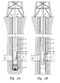
- the present invention is carried by a down hole tool, such as the drilling tool 10a of Fig. 1 or the wireline tool 10b of Fig. 2.
- the present invention may also be used in other downhole tools adapted to draw fluid therein, such as coiled tubing, casing drilling and other variations of downhole tools.
- Fig. 1A depicts the downhole drilling tool 10a advanced into the earth to form a wellbore or borehole 14.
- the drilling tool 10a has a bit 30 at an end thereof adapted to cut into the earth to form the wellbore 14.
- the drilling tool 10a is deployed into the wellbore via a drill string 28.
- a drilling mud (not shown) is pumped into the wellbore through the drilling string 28 and out the bit 30.
- the mud is circulated up the wellbore 14 and back to the surface for recycling.
- the mud seeps into the walls 17 of the wellbore 14 and penetrates surrounding formations.
- the mud lines the wellbore wall 17 and forms a mudcake 15 along the wellbore wall 17. Some of the mud penetrates the wall 17 of the wellbore 14 and forms an invaded zone 19 along the wellbore wall 17. As shown, the borehole 14 penetrates a formation 16 containing a virgin fluid 22 therein. A portion of the drilling mud seeps into the formation 16 along the invaded zone and contaminates the virgin fluid 22. The contaminated virgin fluid is indicated by reference number 20.
- the downhole drilling tool 10a is provided with a fluid communication device, such as a probe 2a.
- the probe 2a extends from the downhole drilling tool and forms a seal with the mudcake 15 lining the wellbore wall 17. Fluid then flows into the downhole tool 10a via the probe 2a. As shown, virgin fluid eventually enters the downhole tool.
- the drilling tool 10a is removed and a separate downhole wireline tool is deployed into the wellbore 14 to perform tests and/or take samples.
- a wireline tool 10b is positioned in the wellbore and a probe 2b is extended therefrom to contact the wellbore wall.
- the probe 2b may also be used to draw fluid into the downhole tool.
- the downhole tool operates, be it a wireline, while drilling, etc., the probe and may be designed to improve durability, sealing capability, adaptability to various wellbore conditions and sizes, and deformation resistance, among others.
- the probes 2a, 2b may be used in a variety of tools. As shown below, the probes 2a, 2b may also be configured to operate with multiple inlets. Accordingly, the probe and packer configurations disclosed hereafter may be adapted for use in various tools and having one or more inlets.
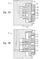
- the probe 2a includes a base 210, a packer 212, an inlet 215 and a flowline 216.
- the base 210 includes a platform 218 and pistons 220.
- the base 210 is extendable and retractable from the downhole drilling tool by selective activation of the pistons 220.
- the pistons 220 are slidably movable in chambers 222 of the downhole drilling tool 10a.
- An actuator (not shown) is provided to selectively manipulate the pressures in the chambers to extend and retract the pistons.
- the packer 212 is positioned on the platform 218. As shown, the packer 212 may be secured to a plate 232 which is then secured to the platform 218. Alternatively, the packer 212 may be secure to the platform 218 without the use of the plate 232. The packer 212 and/or plate 232 may be secured to the platform by bonding, mechanical coupling or other techniques.
- the packer is typically provided with a surface adapted to conform to the platform 218. In some cases, the packer 212 is positioned on a plate that is operatively connected to platform 218 as will be described more fully below.
- the packer 212 is typically an elliptical, circular or oblong member having a hole 230 extending therethrough for the passage of fluids.
- the optional tube 214 extends into the hole 230.
- the tube 214 defines in part an inlet 215 for the passage of fluid, with the hole 230 also defining part of the inlet 215.
- the tube 230 is adapted to extend and retract to make selective contact with the formation.
- the tube 230 may be provided with a filter to screen contaminates as the fluid enters the downhole tool.
- the packer 212 surrounds the inlet to provide a seal with the formation 16.
- the seal may be used to prevent fluid from passing between the inlet 215 and the wellbore wall 17.
- the seal is also used to establish fluid communication with the formation so that fluid may pass through the probe 2a without leakage.
- the packer 212 has typically a curved or arcuate outer surface 248 adapted to contact the usually cylindrical wall of the wellbore.
- the arcuate outer circle may form part of a circle, ellipse or other shape.
- the arcuate outer surface 248 may be constructed from a single material, or may be constructed from several sections or materials (see, e.g., Fig. 3D). In some cases, the outer surface 248 may have an arcuate shape also in the vertical direction.
- the packer typically flattens and conforms to the wellbore wall when the probe is pressed against the wall.
- the packer 212 has a lower surface 250 adapted to be secured to the plate 232 and/or platform 218. As will be discussed below, alternate packer shapes may be provided. Typically, as the packer 212 is pressed into contact with the wellbore wall 17, the packer 212 deforms and provides a seal.
- the packer 212 may be provided with a variety of geometries, such as rectangular, oblong, rounded, etc., depending on the desired function. In some cases, the packer 212 may be elongated so that it may extend across more than one formation during operation. One or more probes and/or packers with one or more inlets may be provided. The inlets may be of varied dimension and size as needed for the specific application.
- the outer surface 248 of the packer may be shaped for optimal sealing with the wellbore wall as will be described more fully below.
- the probe 2b is the same as the probe of Fig. 2A, except that the probe 2b has dual packers 312 and 311, dual inlets 315 and 317 and dual flowlines 316 and 318.
- This configuration provides one embodiment of a probe adapted to draw virgin fluid into a first inlet and contaminated fluid into a second inlet as further described, for example, in US Patent No. 6,301 , 959 or US Patent Application No. 2004/0000433 .
- the first inlet 315 is defined by tube 314 positioned in a first hole 330 extending through the packer 311.
- the packer 311 is depicted as an extendable packer adapted to extend from the probe to contact the wellbore wall.
- An actuator (not shown), such as a hydraulic actuator known in the art, may be provided to extend and retract the packer(s) and/or tube 314.
- the second packer 312 is positioned about the packer 311. In this position, the packers are concentric and have a gap therebetween that defines the second inlet 317.
- the first flowline 316 extends from the inlet 315, and the second flowline 318 extends from the inlet 317 and into the downhole tool.
- Fig. 2B shows two concentric packers with a gap therebetween defining the second inlet 317
- the probe 2b may be provided with a single unitary packer with a channel and/or inlets extending therethrough. These channels and/or inlets may be supported by inserts and define inlets for drawing fluid into the downhole tool. Examples of a probe with additional inlets is described in more detail in co-pending US Patent Application Ser. No. 10/960,403 , the entire contents of which are hereby incorporated by reference.
- Figs. 2A and 2B depict various options for probe configurations. Specifically, Fig. 2A depicts a probe with a single inlet 215, a packer 212, and a tube 214 extendable relative to the packer 212. Fig. 2B depicts a probe with multiple inlets 315, 317, multiple packers 311, 312, a fixed tube, a packer 311 and a packer 312. These options may be interchangeable and provided as desired.
- the flowline 216 extends from the inlet 215 to the downhole tool.
- pressure in the downhole tool is lowered to draw fluid therein.
- mudcake and contaminated fluid is drawn into the downhole tool.
- Filters are often provided in the probe to remove debris from the fluid as it passes into the downhole tool.
- contamination decreases and more virgin fluid enters the downhole tool.
- Fluid may tested using measuring devices and/or collected in sample chambers (not shown). In some cases, fluid is dumped into the wellbore, or ejected into the formation.
- Probe 2b operates in a similar manner as described above.
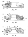
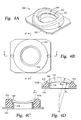
- Figs. 3A-3K depict various packer configurations and packer features that may be used with the probes of Figs. 2A and/or 2B.
- These packers are provided with various techniques for supporting the packer and various devices for sealing with the wellbore wall. These devices may cooperate to establish a good seal with the formation.
- Each of these packers may be provided with one or more holes that may be used (with or without tubes) to define one or more inlets for the passage of fluid therethrough. As described above, the packers and/or inlets may have a variety of dimensions and configurations.
- a packer 300a illustrated in Fig. 3A may be constructed of a seal material 301a.
- the packer 300a is made of a resilient material, preferably an elastomeric material, such as a rubber. Other materials, such as peek, or composite materials comprising rubber and Teflon amongst others, may also be used.
- the seal material is sufficiently deformable such that it is capable of forming a seal with the mudcake and is able to conform to the wall of the wellbore.
- the seal material is also preferably strong enough such that it maintains sufficient shape to maintain the seal.
- the seal material is also preferably durable enough to prevent damage to the packer as the tool is exposed to harsh wellbore conditions and downhole operations.
- the packer 300a is attached to the plate 232a.
- the packer and plate (if a plate is provided) may then be operatively connected to the platform of the probe as shown in Fig. 2A.
- the packer 300a is provided with a hole 342a therethrough adapted to receive a tube similar to the one shown to Fig. 2A if provided.
- the hole 342a has a first portion 344a at an entrance defining an inlet 345a through the packer, and a second portion 346a extending from the first portion 344a to a lower surface 350a of the packer.
- the first portion is cylindrical, and the second portion is tapered.
- the packer as shown in Fig. 3A has an arcuate outer surface 348a adapted to contact the wall of the wellbore. The dimension of the inlet and/or packer may be varied as desired for optimum seal and/or flow capabilities.
- the packer of Fig. 3A is provided with a support in the form of reinforcers 360.
- These reinforcers may be fabric, metal or other devices positioned in the rubber. For example, wires or threads may be extended through the rubber.
- the packer may be formed by layering sheets of rubber coated reinforcers 360. Alternatively, the packer may be formed by extruding rubber over groups of the reinforcers. In one example, the packer is forty percent rubber and sixty percent metal mesh. These reinforcers 360 assist in strengthening the packer to reduce the amount of deformation that occurs as the packer is pressed against the wellbore wall.
- the reinforcers 360 may be selectively placed in the packer to maximize strength, sealing capability and or durability. For example, it may be desirable to have fewer reinforcers 360 near the outer surface 348a where the seal is made, and/or more reinforcers along an outer periphery 352a and/or inner periphery 362a to prevent the packer from substantially flattening.
- Fig. 3B depicts a packer 300b attached to plate 232b.
- the packer has a hole 342b extending therethrough.
- the packer includes a sealing material 301b and a support in the form of a support member 303.
- the support material is attached to the plate and has a cavity 305 that extends from an outer surface 348b. The cavity is adapted to receive the sealing material 301b.
- the support member 303 is preferably a material with less elastic deformation than the sealing material 301 b.
- the support material may be, for example, peek, Teflon, composite or other material that is adapted to provide support and/or reduce the deformation of the packer.
- the sturdy support material is adapted to maintain the shape of the probe and prevent deformation as the probe is pressed against the wellbore wall.
- the sealing material 301b is preferably an elastomeric material, such as the material 301a of Fig. 3A.
- the sealing material forms a ring around an inlet 345b and deforms about the inlet to form the seal.
- the sealing material 301b may be bonded to the support member 303.
- the sealing and support materials may also be extruded or heated together to form a unitary packer.
- Fig. 3C depicts a packer 300c.
- the packer 300c includes a sealing material 301c and a support in the form of a support member 309.
- the support member 309 may be similar the support member 303 of Fig. 3B.
- the plate 232c is formed integrally support member 309.
- the support member 309 has an opening or aperture 351 extending about a hole 342c extending through the packer 300c.
- the sealing material 301c is positioned in the channel 351.
- the sealing material 301c may be a rubber insert, such as a disk or ring that may define a portion of an inlet 345c of the packer. In this configuration, a larger portion of the material insert is deformable.
- the sealing material 301c is adjacent the inlet.
- Fig. 3D depicts a packer 300d positioned on a plate 232d.
- the packer has a hole 342d therethrough and includes a sealing material 301d adapted to seal with the wellbore wall.
- the packer is provided with a support in the form of support member 375d is positioned about a periphery 352d of the packer.
- the support member 375d includes a first ring 374d, and a second ring 376d.
- the first ring 374d may be a composite ring adapted to support the outer periphery 352d of the packer. As shown, the first ring extends from an outer surface 348d of the packer and is affixed to the plate 232d.
- the composite material may be provided with some ability to deform to allow the packer to bend as it contacts the wellbore wall.
- the second ring 376d is preferably made of a sturdy material, such as metal, that permits little or no deformation.
- the second ring 376d is depicted as being attached to plate 232d, but extending a distance therefrom.
- the second ring 376d is positioned about a portion of the composite ring to provide support thereto.
- One or more rings of various rigidity may be positioned about the periphery of the packer 300d to provide peripheral support thereto.
- the rings may surround the packer to provide support thereto.
- the rings may be positioned and made of select materials to provide the desired rigidity, deformation and/or durability.
- the packer 300d is provided with a flat outer surface 348d. This figure demonstrates that a variety of configurations may be provided. However, the outer surface 348d may be adjusted to provide the desired sealing capability.
- Fig. 3E depicts a packer 300e that may be attached to, for example, a platform similar to platform 218 of Fig. 2A.
- the packer 300e includes a sealing material 301e.
- Packer 300e is provided with a support in the form of a support system 375e that is positioned about a periphery 352e of the packer to provide support thereto.
- the support system 375e includes a first ring 380e and a second ring 382e.
- the first ring 380e is slidably positioned within the second ring 382e.
- the first ring 380e is adapted to telescopically extend and retract within the second ring 382e and with the packer to provide support.
- the rings 380e, 382e are provided with corresponding lips 381e, 383e, respectively, to act as stops to retain the first ring in the second ring.
- the rings 380e, 382e are preferably made of a sturdy material, such as metal to provide support and resistance to deformation to the outer periphery of the packer.
- the rings 380e, 382e may be provided with teeth (not shown) to assist the rings in attaching to the sealing material.
- the sealing material 301e has a hole 342e therethrough and an outer surface 348e that is generally concave. However, around adjacent hole 342e, the sealing material 301e has a raised portion 390e. The raised portion 390e is generally convex to provide an initial contact surface with the wellbore wall. Additionally, the packer 300e is provided with a slot or void 391e adapted to permit movement of the first ring 380e about the periphery of the packer and/or to provide an area for sealing material to move as it deforms. Keyways and/or ears may be provided in the rings and/or sealing material to prevent relative rotation therebetween.
- Packer 300f of Fig. 3F is similar to the packer 300e of Fig. 3E, except that the outer metal ring is provided with mud holes 395 through second ring 382f. This may be used to permit fluid flow. This may assist in preventing pressure buildup within the packer.
- Fig. 3G depicts a packer 300g positioned on a plate 232g.
- the packer includes a sealing material 301g with a support in the form of a support ring 375g about a periphery thereof.
- the support ring includes an embedded ring 398g, and a peripheral ring 399g.
- the embedded ring is connected to the plate by bolts or screws 408g and extends into the sealing material 301g.
- the embedded ring may be a metal ring adapted to provide internal support to the sealing material.
- the peripheral ring 399g is positioned on the plate 232g and extends a distance therefrom.
- the peripheral ring 399g is positioned about the periphery of the packer.
- a portion of the peripheral ring 399g is positioned between a shoulder 410g of the embedded ring and the plate 232g.
- the peripheral ring 399g may be secured to the plate 232g by bonding and/or by the embedded ring 398g.
- the peripheral ring 399g may be of the same material as the sealing material 301g, or form an unitary part with the sealing material 301g after heating.
- the peripheral ring 399g may also be made of a stiff material such as peek or metal.
- Fig. 3H depicts a packer 300h secured to plate 232h.
- the packer 300h includes a sealing material 301h.
- the packer 300h is provided with a support in the form of a support ring 375h positioned about a periphery 352h of the packer.
- the support ring 375h includes an embedded ring 398h, a peripheral ring 399h and a spring 412.
- the embedded ring 398h and bolts 408h may be the same as the embedded ring 398g and bolts 408g of Fig. 3G.
- the support ring 399h may be the same as the support ring 399g of Fig. 3G, except that it has a cavity 414 extending therein adapted to receive the spring 412.
- the spring 412 is operatively connected to the plate 232h and the peripheral ring 399h to permit bending thereof.
- the spring 412 preferably reduces loads on the packer, and permits some movement of the peripheral
- Fig. 3I depicts a packer 300i attached to plate 232i.
- the packer 300i has a hole 342i therethrough.
- the packer 300i includes a sealing material 301i and a support in the form of a support ring 375i.
- the support ring 375i includes a peripheral support 399i, and an embedded support 398i.
- the peripheral support 399i has a cavity 416 extending inwardly from an outer surface 348i of the packer.
- the peripheral support provides resistant to deformation along the periphery.
- the cavity 416 is adapted to receive the sealing material 301i and the embedded support 398i.
- the embedded ring 398i is positioned in the cavity between the sealing material and the peripheral support.
- the embedded support provides some support but allows more deformation than the peripheral support.
- the sealing material 301 is positioned in the cavity 416 and defines a portion of the outer surface 348i of the packer.
- the sealing material 301i is preferably sufficiently flexible to permit a good seal.
- the sealing material 301 is supported by the embedded and peripheral supports.
- the inner peripheral support is provided to assist in preventing the sealing material from flowing into the hole and cutting off flow as it is pressed against the wellbore wall.
- the embedded and peripheral supports may be attached to plate 232i by bolts or screws 408i.
- the sealing material may be bonded to the embedded and/or peripheral supports.
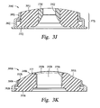
- Fig. 3J illustrates a packer 300j positioned on a plate 232j.
- the packer has a hole 342j extending therethrough.
- the packer includes a packer material 301j.
- the packer is provided with supports in the form of an outer peripheral support system 375j and an inner peripheral support ring 376j.
- the inner peripheral support ring 376j is preferably made of a material with less elasticity that the sealing member to provide support thereto.
- the inner peripheral support ring may be of the same material as the outer peripheral support system 375j. The material may be selected based on its ability to provide support and prevent deformation as desired.
- the inner peripheral support 376j is positioned about hole 342j to provide support to the inner periphery of the packer to assist the sealing material in forming a seal with the wellbore wall.
- the inner peripheral support 376j is also provided to prevent extrusion of the sealing material into the hole 342j where it would limit flow therethrough.
- the outer peripheral support ring system 375j includes an inner ring 380j and an outer ring 382j.
- the packers and/or probes provided herein may be provided with inner, peripheral and embedded supports.
- Various types of inner, peripheral and/or embedded supports may be used with a variety of probe configurations.
- the shape of the packer may be modified to receive the support and/or form a seal with the wellbore wall.
- the materials, configurations and shapes of the packers set forth herein may be interchanges and selected for the specific application.
- a packer 300k includes a inner support member 376k.
- the inner support member 376k may at least partially define an inlet 345k of the packer and may extend from an outer surface 348k of the packer to a lower surface 350k of the packer.
- the inner support 376k may further include a lip 377 extending outwardly at the outer surface 348k of the packer to partially define the outer surface 348k.
- at least a portion of a packer material 301k extends beyond the lip 377 to ensure a seal against the borehole wall.
- the inner support member 376k may also define at least a portion of a hole 342k to provide support to the inner periphery of the packer to assist the sealing material in forming a seal with the wellbore wall.
- An outer periphery 352k of the packer 300k includes a support system 375j including an inner ring 380k and an outer ring 382k.
- Fig. 3L depicts a packer 300L that includes a sealing material 301L with embedded sensors 410.
- the packer 300L is positioned on a plate 232L.
- the packer 300L is depicted with tube 230L extending therethrough.
- the sensors 410 may be positioned about the packer 300L, the tube 230L or other portions of the probe to measure downhole parameters.
- the sensors 410 are used to measure stresses on the packer 300L.
- the sensors 410 may be used to measure formation and/or wellbore fluid parameters. Other characteristics of downhole conditions and/or operations may also be measured by these sensors.
- These sensor 410 may be, for example pressure gauges, fluid analyzers, mechanical stress sensors, temperature sensors, displacement sensors, load sensors, acoustic sensors, optical sensors, radiological sensors, magnetic sensors, electrochemical sensors, or other sensor capable of taking downhole measurements.
- Such sensors 410 may be extruded into the sealing material, or attached to the probe at the desired location. When embedded in the sealing material, the sensors 410 may also provide support thereto.
- the sensors may be operatively connected, using wired or unwired techniques, to processors, memories or other devices capable of collecting, storing and/or analyzing the data collected by the sensors and known to those of ordinary skill in the art.
- the sensors 410 may be provided with antennas or other communication devices for transferring data from the sensors to the downhole tool and/or surface.
- Fig. 3M depicts a packer 300m affixed to plate 232m.
- the packer includes a sealing material 301m.
- the packer 300m is a hollow ring.
- the packer 300m may be provided with an inlet 412 for receiving a fluid.
- the packer 300m may then be selectively inflated and/or deflated as desired to achieve the desired rigidity, seal or other performance characteristic.
- the packer 300m may be inflated in the same manner as the dual packers are inflated. Techniques for inflating dual packers are described in more detail in US Patent No. 4,860,581 , the entire contents of which is hereby incorporated by reference.
- a packer 300n includes an inner packer 311n and an outer packer 312n.
- Outer packer 312n includes a sealing material 301n and supports in the form of reinforcers 360n. Any of the supports of the previous figures may be used.
- Inner packer 311n includes the sealing material 301n with a support in the form of a spring 414.
- the spring 414 is adapted to provide support while permitting some deformation as the packer presses against the wellbore wall.
- the inner packer may be movable as shown in Fig. 2B, or fixed to plate 232n.
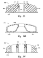
- Figs. 4A-D depicts the dimension of a packer 500.
- the packer 500 is made of a sealing material 501 affixed to plate 532.
- the packer has a hole 530 extending therethrough.
- the packer is shown with tube 514 positioned therein.
- the packer 500 has a generally circular shape and is provided with a tapered inner surface 505 and a contoured outer surface 515.
- the inner surface 505 is preferably angled away from the tube 514 at an angle ⁇ to prevent abrasion or excessive contact therebetween.
- FIG. 4C is a cross-sectional view of the probe of Fig. 4B along line C-C.
- the vertical portion of the probe has a flat outer surface 515a that conforms to the vertical portion of the wellbore wall.
- the shape of the tube 514 is also substantially flat so that it will also conform to the vertical portion of the wellbore wall when the probe is engaged.
- Figure 4D is a cross-sectional view of the probe of Fig. 4B along line D-D.
- the curved portion of the probe has an arcuate outer surface 515b that conforms to the arcuate shape wellbore wall.
- the tube 514 is shaped to substantially conform to the arcuate shape of the wellbore wall as indicated by R1
- the outer surface of the packer has a slightly exaggerated shape as indicated by R2.
- the dashed line 516 represents an outer surface having an arcuate packer shape that conforms to the wellbore wall.
- Solid line 518 depicts an extended outer surface that has the radius R2 that extends beyond the radius of the wellbore or R1. This extended radius of the packer is intended to equalize the forces about the packer.
- the probes may have one or more inlets for receiving fluids.
- the probes may be adapted to receive fluid into or eject fluid from the downhole tool.
- the packers may also be provided with reinforcement, sensors, inflation or other devices.
- Other probe devices, such as filters, valves, actuators and other components may be used with the probe(s) described herein.
- the relative shape of the packer may be manipulated to obtain a more homogenous contact pressure distribution of the packer as it is pressed against the borehole wall.
- This is contrary to currently available packers that have a non-homogenous contact pressure distribution about the packer.
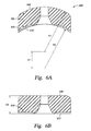
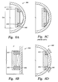
- currently available packers are commonly shaped in an attempt to match a profile of the borehole wall, as is illustrated in Fig. 5A.
- the packer has a constant thickness along a vertical plane of the packer as illustrated in Fig. 5B, and a variable thickness along a horizontal plane as seen in Fig. 5C to accommodate for the curvature of the borehole wall.
- the packer is thicker along its vertical plane than its horizontal plane. This variation of thickness may cause a non-homogenous contact pressure distribution on the wellbore wall when the packer is applied to the wall. This non-homogenous contact pressure may provide leak paths between the packer and the borehole wall. More particularly, the areas about the packer having the least contact pressure will provide the greatest chance for a leak path. As this particular packer is pressed against the borehole wall, the areas of undergoing the least contact pressure and, hence, the greatest possibility for a leak path, are located along the vertical axis as is identified in Fig. 5A by areas "LP".
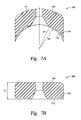
- an outer surface 648 of the packer 600 has a generally cylindrical shape with a horizontal curvature radius R1 that is equal to, or at least substantially similar to, a radius of the wellbore.
- An inner surface 650 of the packer may be bonded or otherwise attached to a plate 632 having a generally cylindrical shape that has a curvature R2 that is equal to, or at least substantially similar to, the curvature radius R1.
- the centers of curvature of inner surface 648 and outer surface 650 corresponding to radii R1 and R2 respectively, are a distance D1 apart which, in this embodiment, is equal to, or at least substantially similar to D2 - the substantially uniform distance between the outer and inner surfaces 648, 650 of the packer 600, or the thickness of the packer 600.
- an outer surface 748 of a packer 700 has a generally cylindrical shape with a horizontal curvature radius R1 that is equal to, or at least substantially similar to, a radius of the wellbore.
- An inner surface 750 of the packer 700 may be bonded or otherwise attached to a plate 732, and has a generally cylindrical shape that has a horizontal curvature radius R2.
- the outer surface 748 and inner surface 750 have the same center of curvature.
- R1 is equal, or at least substantially similar, to R2 plus a distance D 1 which is the distance between the outer and inner surfaces 748, 750 of the packer, or is the thickness of the packer.
- an outer surface 848 of a packer 800 has a generally cylindrical shape with a horizontal curvature radius R1 that is less than a radius of the wellbore.
- An inner surface 850 of the packer 800 may be bonded or otherwise attached to a generally flat, planar, or at least less curved, plate 832.
- the packer 800 will on average be thicker along its vertical plane (Fig. 8B) than its horizontal plane (Fig. 8A), and will be configured such that the curvature of the packer is less than the borehole wall.
- the thicker portions of the packer such as the areas along the vertical plane and the areas around the inner diameter of the packer, will generally touch or abut the borehole wall before the thinner areas of the packer as the packer is compressed against the borehole wall.
- the thicker portions of the packer will undergo greater deformation compared to the thinner areas, thereby creating a substantially even stress distribution around the packer as is illustrated with arrows in Fig. 8D. As will be shown below, this hold true for many variations of borehole diameters.
- testing determined that a packer having a curvature or diameter of 6.125" (Dia. in Fig. 8A) will create a proper seal against a borehole having diameters of 8", 10" and 12.25". In testing it was determined that a packer having a curvature of 6.125" may also sufficiently seal against a borehole wall having a curvature of 6".
- the testing was conducted by engaging a dual inlet packer (see Figs. 2B and 3N) with a portion of a casing and placing a pressurized source of air at approximately 110 psi into fluid communication with the inlets of the packer. The packers were then checked to determine if a leak from an inner or outer packer was present. If no leak was detected, then the seal between the packer and the casing would be considered to be proper.
- a packer 900 shown in Fig. 9 may further include inner and/or outer support members 976, 975 designed to accommodate the deformation of the inner and outer edges of the packer 900.
- inner and/or outer support members 976, 975 designed to accommodate the deformation of the inner and outer edges of the packer 900.
- the edges or peripheries 952a, 952B of the packer may creep outwardly to accommodate the compressive forces.
- An outer and/or inner support member having a straight or non-curved edge disposed around a packer may pinch, cut and/or weaken the packer 900.
- ends 980, 981 of the support members 976, 975 may include a curved or radius edge 979, 977 to permit the packer material displaced during compression of the packer against the borehole wall to roll or abut a smooth or curved portion to prevent damage to the packer 900.
- the support members 976, 975 may be disposed along the inner and outer peripheries, respectively, of the packer 900, such that the ends 980, 981 are disposed between an inner surface 950 and an outer surface 948 of the packer 900. As illustrated in Fig.
- the peripheral sides of the packer will gradually engage the curved or radiused 979, 977 edges of the support members 976, 975 as the packer 900 is compressed against the borehole wall, thereby preventing the packer from becoming pinched or cut.
- the internal and/or external support may remain fixed as the probe extends, or extend with the probe.
- the supports When extendable, the supports may be telescopically extended, spring loaded, and adjustable.
- the external support may be connected to the downhole tool and/or the probe.
- Various combinations of the supports and the amount of surface area contact with the packer are envisioned.
Landscapes
- Life Sciences & Earth Sciences (AREA)
- Engineering & Computer Science (AREA)
- Geology (AREA)
- Mining & Mineral Resources (AREA)
- Physics & Mathematics (AREA)
- Environmental & Geological Engineering (AREA)
- Fluid Mechanics (AREA)
- General Life Sciences & Earth Sciences (AREA)
- Geochemistry & Mineralogy (AREA)
- Consolidation Of Soil By Introduction Of Solidifying Substances Into Soil (AREA)
- Geophysics And Detection Of Objects (AREA)
- Investigation Of Foundation Soil And Reinforcement Of Foundation Soil By Compacting Or Drainage (AREA)
Applications Claiming Priority (2)
| Application Number | Priority Date | Filing Date | Title |
|---|---|---|---|
| US75101705P | 2005-12-16 | 2005-12-16 | |
| US11/609,188 US20070151727A1 (en) | 2005-12-16 | 2006-12-11 | Downhole Fluid Communication Apparatus and Method |
Publications (2)
| Publication Number | Publication Date |
|---|---|
| EP1798368A2 true EP1798368A2 (fr) | 2007-06-20 |
| EP1798368A3 EP1798368A3 (fr) | 2007-10-24 |
Family
ID=37890616
Family Applications (1)
| Application Number | Title | Priority Date | Filing Date |
|---|---|---|---|
| EP06077259A Withdrawn EP1798368A3 (fr) | 2005-12-16 | 2006-12-15 | Appareil de sondage de paroi latérale |
Country Status (4)
| Country | Link |
|---|---|
| US (3) | US20070151727A1 (fr) |
| EP (1) | EP1798368A3 (fr) |
| CA (1) | CA2571149C (fr) |
| MX (3) | MX356660B (fr) |
Cited By (1)
| Publication number | Priority date | Publication date | Assignee | Title |
|---|---|---|---|---|
| GB2489055A (en) * | 2011-03-18 | 2012-09-19 | Weatherford Lamb | Cylindrical shaped snorkel interface on evaluation probe |
Families Citing this family (23)
| Publication number | Priority date | Publication date | Assignee | Title |
|---|---|---|---|---|
| US8015867B2 (en) * | 2008-10-03 | 2011-09-13 | Schlumberger Technology Corporation | Elongated probe |
| US9470058B2 (en) * | 2009-12-10 | 2016-10-18 | Schlumberger Technology Corporation | Ultra high temperature packer by high-temperature elastomeric polymers |
| RU2431035C2 (ru) * | 2009-12-31 | 2011-10-10 | Шлюмберже Текнолоджи Б.В. | Способ определения момента прорыва пластового флюида |
| US20110214879A1 (en) * | 2010-03-03 | 2011-09-08 | Baker Hughes Incorporated | Tactile pressure sensing devices and methods for using same |
| WO2011155932A1 (fr) * | 2010-06-09 | 2011-12-15 | Halliburton Energy Services, Inc. | Procédé d'acquisition de données et de qualité de positionnement de sonde d'évaluation de formation |
| US8453725B2 (en) | 2010-07-15 | 2013-06-04 | Schlumberger Technology Corporation | Compliant packers for formation testers |
| US20130062073A1 (en) * | 2011-09-14 | 2013-03-14 | Nathan Landsiedel | Packer Assembly with a Standoff |
| EP2599954A3 (fr) * | 2011-11-30 | 2014-04-09 | Services Pétroliers Schlumberger | Packer de sonde et son procédé d'utilisation |
| US20140015201A1 (en) * | 2012-07-13 | 2014-01-16 | Halliburton Energy Services, Inc. | High pressure seal back-up |
| US9416657B2 (en) | 2012-11-15 | 2016-08-16 | Schlumberger Technology Corporation | Dual flowline testing tool with pressure self-equalizer |
| US9382793B2 (en) | 2012-12-20 | 2016-07-05 | Schlumberger Technology Corporation | Probe packer including rigid intermediate containment ring |
| US9115571B2 (en) | 2012-12-20 | 2015-08-25 | Schlumberger Technology Corporation | Packer including support member with rigid segments |
| BR112015015113A2 (pt) * | 2013-01-03 | 2017-07-11 | Halliburton Energy Services Inc | sistema e método para coletar um fluido de formação representativo durante operações de teste de fundo do poço |
| US9284838B2 (en) | 2013-02-14 | 2016-03-15 | Baker Hughes Incorporated | Apparatus and method for obtaining formation fluid samples utilizing independently controlled devices on a common hydraulic line |
| US9752432B2 (en) * | 2013-09-10 | 2017-09-05 | Schlumberger Technology Corporation | Method of formation evaluation with cleanup confirmation |
| US10215022B2 (en) | 2013-12-19 | 2019-02-26 | Schlumberger Technology Corporation | Guard filtering system for focused sampling probe |
| EP3173574A1 (fr) * | 2015-11-26 | 2017-05-31 | Services Pétroliers Schlumberger | Ensemble et procédé pour une garniture d'étanchéité extensible |
| EP3199942A1 (fr) * | 2016-02-01 | 2017-08-02 | Openfield | Sonde d'analyse optique des propriétés d'un fluide de fond de puits comportant une sonde d'analyse dotée d'une pointe optique amovible |
| WO2017213632A1 (fr) * | 2016-06-07 | 2017-12-14 | Halliburton Energy Services, Inc. | Outil de vérification de formation |
| US10753172B2 (en) * | 2016-11-04 | 2020-08-25 | Schlumberger Technology Corporation | Downhole formation testing tools including improved flow routing device |
| US10738600B2 (en) | 2017-05-19 | 2020-08-11 | Baker Hughes, A Ge Company, Llc | One run reservoir evaluation and stimulation while drilling |
| US11230923B2 (en) * | 2019-01-08 | 2022-01-25 | Mark A. Proett | Apparatus and method for determining properties of an earth formation with probes of differing shapes |
| CN112696188B (zh) * | 2020-12-09 | 2023-10-31 | 王少斌 | 一种环形可拆卸橡胶探头推靠器 |
Citations (3)
| Publication number | Priority date | Publication date | Assignee | Title |
|---|---|---|---|---|
| US960403A (en) | 1909-08-21 | 1910-06-07 | Edward A Richter | Propeller. |
| US2674313A (en) | 1950-04-07 | 1954-04-06 | Lawrence S Chambers | Sidewall formation fluid sampler |
| US4860581A (en) | 1988-09-23 | 1989-08-29 | Schlumberger Technology Corporation | Down hole tool for determination of formation properties |
Family Cites Families (24)
| Publication number | Priority date | Publication date | Assignee | Title |
|---|---|---|---|---|
| US3173485A (en) * | 1958-08-26 | 1965-03-16 | Halliburton Co | Well formation isolation apparatus |
| US3344860A (en) * | 1965-05-17 | 1967-10-03 | Schlumberger Well Surv Corp | Sidewall sealing pad for borehole apparatus |
| US3295615A (en) * | 1965-10-22 | 1967-01-03 | Schlumberger Well Surv Corp | Formation-testing apparatus |
| US3565169A (en) * | 1969-04-02 | 1971-02-23 | Schlumberger Technology Corp | Formation-sampling apparatus |
| US3688849A (en) * | 1970-02-20 | 1972-09-05 | Halliburton Co | Method and apparatus for releasing a perforation and sealing tool from a well bore |
| US4287946A (en) * | 1978-05-22 | 1981-09-08 | Brieger Emmet F | Formation testers |
| US4936139A (en) * | 1988-09-23 | 1990-06-26 | Schlumberger Technology Corporation | Down hole method for determination of formation properties |
| US6672460B2 (en) | 1997-09-02 | 2004-01-06 | Southwestern Wire Cloth, Inc. | Vibrating screen assembly with integrated gasket and frame |
| US6135204A (en) * | 1998-10-07 | 2000-10-24 | Mccabe; Howard Wendell | Method for placing instrumentation in a bore hole |
| US6301959B1 (en) * | 1999-01-26 | 2001-10-16 | Halliburton Energy Services, Inc. | Focused formation fluid sampling probe |
| GB2370882B (en) * | 2000-07-20 | 2004-03-24 | Baker Hughes Inc | Drawdown apparatus and method for in-situ analysis of formation fluids |
| CN100347406C (zh) * | 2000-08-15 | 2007-11-07 | 贝克休斯公司 | 现场确定地层参数的装置和方法 |
| US20050224398A1 (en) | 2001-10-19 | 2005-10-13 | Largent David W | Vibratory separators and sealing screens |
| US20050103689A1 (en) | 2001-10-19 | 2005-05-19 | Schulte David L.Jr. | Sealing screen assemblies and vibratory separators |
| US6658930B2 (en) * | 2002-02-04 | 2003-12-09 | Halliburton Energy Services, Inc. | Metal pad for downhole formation testing |
| WO2003097999A1 (fr) * | 2002-05-17 | 2003-11-27 | Halliburton Energy Services, Inc. | Appareil d'essai de couches mwd |
| US6964301B2 (en) * | 2002-06-28 | 2005-11-15 | Schlumberger Technology Corporation | Method and apparatus for subsurface fluid sampling |
| US7128144B2 (en) * | 2003-03-07 | 2006-10-31 | Halliburton Energy Services, Inc. | Formation testing and sampling apparatus and methods |
| US7036641B2 (en) * | 2003-11-19 | 2006-05-02 | Fashion Accessory Bazaar Llc | Backpack with removable handle and wheel assembly |
| US7121338B2 (en) * | 2004-01-27 | 2006-10-17 | Halliburton Energy Services, Inc | Probe isolation seal pad |
| US7757864B2 (en) | 2004-06-15 | 2010-07-20 | M-I L.L.C. | Screen assembly designed to conform to the radius of vibrating shakers with crowned decks |
| US7458419B2 (en) * | 2004-10-07 | 2008-12-02 | Schlumberger Technology Corporation | Apparatus and method for formation evaluation |
| US7114385B2 (en) * | 2004-10-07 | 2006-10-03 | Schlumberger Technology Corporation | Apparatus and method for drawing fluid into a downhole tool |
| US8312996B2 (en) | 2005-01-21 | 2012-11-20 | Derrick Corporation | Vibratory material screen with seal |
-
2006
- 2006-12-11 US US11/609,188 patent/US20070151727A1/en not_active Abandoned
- 2006-12-13 CA CA002571149A patent/CA2571149C/fr not_active Expired - Fee Related
- 2006-12-15 MX MX2011007875A patent/MX356660B/es unknown
- 2006-12-15 EP EP06077259A patent/EP1798368A3/fr not_active Withdrawn
- 2006-12-15 MX MX2018000034A patent/MX370373B/es unknown
- 2006-12-15 MX MXPA06014755A patent/MXPA06014755A/es unknown
-
2010
- 2010-03-03 US US12/716,882 patent/US8220536B2/en not_active Expired - Fee Related
-
2011
- 2011-08-05 US US13/198,973 patent/US8561686B2/en not_active Expired - Fee Related
Patent Citations (3)
| Publication number | Priority date | Publication date | Assignee | Title |
|---|---|---|---|---|
| US960403A (en) | 1909-08-21 | 1910-06-07 | Edward A Richter | Propeller. |
| US2674313A (en) | 1950-04-07 | 1954-04-06 | Lawrence S Chambers | Sidewall formation fluid sampler |
| US4860581A (en) | 1988-09-23 | 1989-08-29 | Schlumberger Technology Corporation | Down hole tool for determination of formation properties |
Cited By (3)
| Publication number | Priority date | Publication date | Assignee | Title |
|---|---|---|---|---|
| GB2489055A (en) * | 2011-03-18 | 2012-09-19 | Weatherford Lamb | Cylindrical shaped snorkel interface on evaluation probe |
| GB2489055B (en) * | 2011-03-18 | 2013-04-10 | Weatherford Lamb | Cylindrical shaped snorkel interface on evaluation probe |
| US8806932B2 (en) | 2011-03-18 | 2014-08-19 | Weatherford/Lamb, Inc. | Cylindrical shaped snorkel interface on evaluation probe |
Also Published As
| Publication number | Publication date |
|---|---|
| US20070151727A1 (en) | 2007-07-05 |
| US8220536B2 (en) | 2012-07-17 |
| CA2571149C (fr) | 2009-05-05 |
| US20100155053A1 (en) | 2010-06-24 |
| MX370373B (es) | 2019-12-11 |
| US8561686B2 (en) | 2013-10-22 |
| CA2571149A1 (fr) | 2007-06-16 |
| MX356660B (es) | 2018-06-08 |
| US20110284212A1 (en) | 2011-11-24 |
| EP1798368A3 (fr) | 2007-10-24 |
| MXPA06014755A (es) | 2008-10-09 |
Similar Documents
| Publication | Publication Date | Title |
|---|---|---|
| CA2571149C (fr) | Appareil de communication de liquide de fond de trou et methode de fonctionnement | |
| CA2521209C (fr) | Appareil et methode pour prelever un fluide dans un outil de fond | |
| US8015867B2 (en) | Elongated probe | |
| US8522870B2 (en) | Formation testing and sampling apparatus and methods | |
| KR100782105B1 (ko) | 공내 전단강도 시험기 | |
| EP2278123B1 (fr) | Échantillonnage focalisé de fluides de formations terrestres | |
| US20160305240A1 (en) | Downhole Formation Testing and Sampling Apparatus | |
| EP2364394B1 (fr) | Structure de garniture d'étanchéité simple avec capteurs | |
| US6658930B2 (en) | Metal pad for downhole formation testing | |
| CA2814186C (fr) | Systeme et procede relatifs a garniture d'etancheite d'echantillonnage | |
| US20080295588A1 (en) | Formation tester tool seal pad | |
| US9347299B2 (en) | Packer tool including multiple ports | |
| US20180328827A1 (en) | Wellbore material continuous hardness testing methods and tools | |
| US9429013B2 (en) | Optical window assembly for an optical sensor of a downhole tool and method of using same | |
| US9382793B2 (en) | Probe packer including rigid intermediate containment ring | |
| US8905131B2 (en) | Probeless packer and filter systems | |
| EP1247002B1 (fr) | Systeme de diagraphie en cours de forage | |
| US9115571B2 (en) | Packer including support member with rigid segments | |
| US20150090446A1 (en) | Downhole Sampling Probe with Penetrating Inlet and Method of Using Same |
Legal Events
| Date | Code | Title | Description |
|---|---|---|---|
| PUAI | Public reference made under article 153(3) epc to a published international application that has entered the european phase |
Free format text: ORIGINAL CODE: 0009012 |
|
| AK | Designated contracting states |
Kind code of ref document: A2 Designated state(s): AT BE BG CH CY CZ DE DK EE ES FI FR GB GR HU IE IS IT LI LT LU LV MC NL PL PT RO SE SI SK TR |
|
| AX | Request for extension of the european patent |
Extension state: AL BA HR MK YU |
|
| PUAL | Search report despatched |
Free format text: ORIGINAL CODE: 0009013 |
|
| AK | Designated contracting states |
Kind code of ref document: A3 Designated state(s): AT BE BG CH CY CZ DE DK EE ES FI FR GB GR HU IE IS IT LI LT LU LV MC NL PL PT RO SE SI SK TR |
|
| AX | Request for extension of the european patent |
Extension state: AL BA HR MK YU |
|
| 17P | Request for examination filed |
Effective date: 20080424 |
|
| AKX | Designation fees paid |
Designated state(s): AT BE BG CH CY CZ DE DK EE ES FI FR GB GR HU IE IS IT LI LT LU LV MC NL PL PT RO SE SI SK TR |
|
| 17Q | First examination report despatched |
Effective date: 20080612 |
|
| STAA | Information on the status of an ep patent application or granted ep patent |
Free format text: STATUS: THE APPLICATION IS DEEMED TO BE WITHDRAWN |
|
| 18D | Application deemed to be withdrawn |
Effective date: 20100331 |