EP1798043B1 - Differential pressure valve unit - Google Patents
Differential pressure valve unit Download PDFInfo
- Publication number
- EP1798043B1 EP1798043B1 EP06126010A EP06126010A EP1798043B1 EP 1798043 B1 EP1798043 B1 EP 1798043B1 EP 06126010 A EP06126010 A EP 06126010A EP 06126010 A EP06126010 A EP 06126010A EP 1798043 B1 EP1798043 B1 EP 1798043B1
- Authority
- EP
- European Patent Office
- Prior art keywords
- differential pressure
- valve
- valve unit
- pressure valve
- liquid
- Prior art date
- Legal status (The legal status is an assumption and is not a legal conclusion. Google has not performed a legal analysis and makes no representation as to the accuracy of the status listed.)
- Not-in-force
Links
Images


Classifications
-
- B—PERFORMING OPERATIONS; TRANSPORTING
- B41—PRINTING; LINING MACHINES; TYPEWRITERS; STAMPS
- B41J—TYPEWRITERS; SELECTIVE PRINTING MECHANISMS, i.e. MECHANISMS PRINTING OTHERWISE THAN FROM A FORME; CORRECTION OF TYPOGRAPHICAL ERRORS
- B41J2/00—Typewriters or selective printing mechanisms characterised by the printing or marking process for which they are designed
- B41J2/005—Typewriters or selective printing mechanisms characterised by the printing or marking process for which they are designed characterised by bringing liquid or particles selectively into contact with a printing material
- B41J2/01—Ink jet
- B41J2/17—Ink jet characterised by ink handling
- B41J2/175—Ink supply systems ; Circuit parts therefor
- B41J2/17503—Ink cartridges
- B41J2/17556—Means for regulating the pressure in the cartridge
-
- B—PERFORMING OPERATIONS; TRANSPORTING
- B41—PRINTING; LINING MACHINES; TYPEWRITERS; STAMPS
- B41J—TYPEWRITERS; SELECTIVE PRINTING MECHANISMS, i.e. MECHANISMS PRINTING OTHERWISE THAN FROM A FORME; CORRECTION OF TYPOGRAPHICAL ERRORS
- B41J2/00—Typewriters or selective printing mechanisms characterised by the printing or marking process for which they are designed
- B41J2/005—Typewriters or selective printing mechanisms characterised by the printing or marking process for which they are designed characterised by bringing liquid or particles selectively into contact with a printing material
- B41J2/01—Ink jet
- B41J2/17—Ink jet characterised by ink handling
- B41J2/175—Ink supply systems ; Circuit parts therefor
- B41J2/17503—Ink cartridges
- B41J2/17513—Inner structure
Definitions
- the present invention relates to a differential pressure valve unit that is accommodated in a liquid cartridge main body.
- the present invention relates to a structure of a differential pressure valve unit that is mounted to an ink cartridge used for an ink jet recording apparatus.
- an ink cartridge that contains ink is mounted on a holder of the ink j et recording apparatus, and ink is supplied to a recording head.
- a differential pressure valve unit having a valve member that is opened when a predetermined pressure difference between an ink containing portion containing ink and an ink supply portion supplying ink occurs is attached to the ink cartridge.
- the ink cartridge described herein is an example of a liquid cartridge.
- a differential pressure valve unit described in Patent Document 1 has a valve member that can be elastically deformed on the basis of a pressure difference and has a cylindrical edge portion, a valve lid that has a valve member holding portion, substantially having a cylindrical shape, inserted into the edge portion of the valve member to fix the edge portion, and an urging member that is interposed between the valve member and the valve lid and urges the valve member in a direction away from the valve lid.
- Patent Document 1 JP-A-2004-237720 & EP 1428 664 A
- differential pressure valve unit of the ink cartridge since the differential pressure valve does not normally operate when a downstream pressure chamber between a membrane valve serving as the valve member and the valve lid is empty, an ink end may be judged in a state where ink remains in the downstream pressure chamber.
- a space of the downstream pressure chamber is comparatively large and, when the ink end is judged, a large amount of ink remains in the downstream pressure chamber.
- EP 1 016 533 discloses a differential pressure valve unit according to the preamble of claim 1.
- An advantage of some aspects of the invention is to provide a differential pressure valve unit that can reduce the amount of a liquid remaining in a downstream pressure chamber of a differential pressure valve of a liquid cartridge and improve responsibility to a pressure applied to a differential pressure valve unit, and a liquid cartridge having such a differential pressure valve unit.
- a differential pressure valve unit for accommodating in a liquid cartridge main body having: a liquid containing portion containing liquid; and a liquid supply portion supplying a liquid in the liquid containing portion to the outside.
- the differential pressure valve unit includes a membrane valve that is opened when a predetermined pressure difference between the liquid containing portion and the liquid supply portion occurs, and a first member that holds the membrane valve and forms a downstream pressure chamber together with the membrane valve.
- an opposing surface forming the downstream pressure chamber and having a connection port connected to the liquid supply portion has a shape corresponding to a movable range of the membrane valve.
- the shape corresponding to the movable range of the membrane valve is a mortar shape having a deep central portion and a shallow peripheral portion.
- a groove portion is provided at the opposing surface in order to allow the liquid in the downstream pressure chamber to easily flow into the connection port.
- the groove portion may be provided such that an extension line of a center line thereof crosses the connection port.
- the liquid smoothly flows into the connection port through the groove portion.
- the groove portion may be provided so as to cross the connection port.
- the liquid further smoothly flows from the groove portion into the connection port.
- the first member may be substantially formed in a disc shape, and the groove portion may be provided along a diameter direction of the opposing surface.
- the liquid smoothly flows in a diameter direction of the first member. Therefore, the liquid that is distant from the connection port can be smoothly discharged.
- the groove portion may be substantially provided in a linear shape.
- the groove portion may be substantially provided in a ring shape.
- the liquid can smoothly flow over a comparatively wide range of the opposing surface.
- a plurality of groove portions may be provided.
- a plurality of flow passages of the liquid can be secured by the plurality of groove portions. Therefore, the liquid can smoothly flow over a comparatively wide range of the opposing surface.
- the differential pressure valve unit according to the aspect of the invention may further include an urging member that is interposed between the membrane valve and the first member and urges the membrane valve in a direction in which the valve is closed.
- a load can be stabilized by an urging force from the urging member, the opening/closing operation of the differential pressure valve can be reliably performed, and accuracy of the pressure to be generated can be improved.
- the first member may be a valve lid.
- the liquid cartridge may be an ink cartridge. Then, it is possible to obtain an ink cartridge having a small liquid residual quantity that is used in an ink jet printer. Then, in an ink injection process into the ink cartridge, ink is easily filled into the differential pressure valve.
- the shape of the opposing surface that forms the downstream pressure chamber of the first member corresponds to the movable range of the membrane valve, the amount of the liquid remaining in the downstream pressure chamber can be reduced. Further, since the groove portion is provided at the opposing surface in order to allow the liquid to easily flow into the connection port, the liquid in the downstream pressure chamber easily flows through the connection port, and thus responsibility to the pressure of the differential pressure valve unit can be improved.
- liquid cartridge having the above-described differential pressure valve unit for example, an ink cartridge having a small liquid residual quantity that is used in an ink jet recording apparatus can be obtained. Then, in an ink injection process into the ink cartridge, ink is easily filled into the differential pressure valve.
- Fig. 1 is an explodedperspective viewof an ink cartridge including a differential pressure valve unit according to a first embodiment of the invention.
- Fig. 2 is a cross-sectional view of the ink cartridge shown in Fig. 1 taken along the line II-II.
- Fig. 3 is an enlarged cross-sectional view of the differential pressure valve unit shown in Fig. 2 .
- Fig. 4 is a perspective view showing a valve lid of the differential pressure valve unit shown in Fig. 3 .
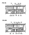
- Figs. 5A and 5B are diagrams illustrating closed and opened states of a valve of the differential pressure valve unit according to the first embodiment of the invention, respectively, and specifically, Fig. 5A is a cross-sectional view showing a state where the valve of the differential pressure valve unit is closed and Fig. 5B is a cross-sectional view showing a state where the valve of the differential pressure valve unit is opened.
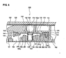
- Fig. 6 is an enlarged cross-sectional view of a differential pressure valve unit according to a second embodiment of the invention.
- Fig. 7 is a perspective view of a first modification of the valve lid of the differential pressure valve unit according to the first or second embodiment of the invention.
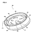
- Fig. 8 is a perspective view of a second modification of the valve lid of the differential pressure valve unit according to the first or second embodiment of the invention.
- Fig. 9 is a perspective view of a third modification of the valve lid of the differential pressure valve unit according to the first or second embodiment of the invention.
- Fig. 10 is an enlarged cross-sectional view of a differential pressure valve unit according to a third embodiment of the invention.
- a valve lid of a differential pressure valve unit is used as a first member.
- Fig. 1 is an exploded perspective view of an ink cartridge including a differential pressure valve unit according to a first embodiment of the invention.
- Fig. 2 is a cross-sectional view of the ink cartridge shown in Fig. 1 taken along the line II-II.
- Fig. 3 is an enlarged cross-sectional view of the differential pressure valve unit shown in Fig. 2 .
- Fig. 4 is a perspective view showing a valve lid of the differential pressure valve unit.
- an ink cartridge main body (liquid cartridge main body) 120 of an ink cartridge 100 includes therein an ink containing portion (liquid containing portion) 101 that is partitioned by a rib or a wall and contains ink, an ink flow passage that extends from the ink containing portion 101 to an inksupplyportion (liquidsupplyportion) 110, and an air connection portionthathasanink-sidepath, an air valve accommodating portion, and an air-side path for connecting the ink containing portion 101 to the air.
- the ink cartridge 100 further includes a differential pressure valve unit 130 serving as an ink supply control unit.
- the ink supply portion 110 is disposed at a lower surface of the ink cartridge 100.
- An ink supply needle of a holder, on which the ink cartridge 100 is mounted, is inserted into the ink supply portion 110, such that ink contained in the ink containing portion 101 is supplied to a recording head of an ink jet recording apparatus.
- the differential pressure valve unit 130 serving as an ink supply control unit supplies ink of the ink containing portion 101 to the ink supply portion 110 by a pressure difference between the ink containing portion 101 and the ink supply portion 110 generated as ink consumes.
- the differential pressure valve unit 130 has a membrane valve 140 that can be elastically deformed and is inserted into a differential pressure valve unit accommodating portion 150, a valve lid 160 that covers the differential pressure valve unit accommodating portion 150, and a coil spring 133 serving as an urging member that is interposed between the membrane valve 140 and the valve lid 160.
- the membrane valve 140 of the differential pressure valve unit 130 has an edge portion 141 that substantially has a cylindrical shape, a thick portion 142 that is disposed in the vicinity of the edge portion 141, a main body portion 143 that is surrounded by the thick portion 142 and is elastically deformed, a valve lid-side protruded portion 144 that protrudes toward the valve lid 160 at the center of the main body portion 143, that is, at a position where the coil spring 133 comes into contact with the main body portion 143, and a main body-side protruded portion 145 that protrudes toward a through hole 152 at a wall surface 151 of the differential pressure valve unit accommodating portion 150.
- the membrane valve 140 is formed of an elastic material more flexible than the ink cartridge main body 120, for example, elastomer.
- the valve lid-side protruded portion 144 substantially has a cylindrical shape, and the outer diameter of its section is slightly larger than the inner diameter of the coil spring 133 before the valve lid-side protruded portion 144 is attached to the coil spring 133. Accordingly, when the valve lid-side protruded portion 144 is inserted into one end of the coil spring 133, the coil spring 133 is accurately positioned and held with respect to the membrane valve 140.
- the valve lid 160 of the differential pressure valve unit 130 has a recess portion 166 that holds the edge portion 141 of the membrane valve 140, a spring receiving portion 167 that substantially has a cylindrical shape and holds the coil spring 133, and a wall surface contact portion 162 that substantially has a cylindrical shape and is disposed in the vicinity of the valve lid 160.
- An opposing surface 161 of the valve lid 160 to the membrane valve 140 has a shape corresponding to a movable range of the membrane valve, that is, a mortar shape. Accordingly, the interference with the valve lid 160 does not occur even though the membrane valve 140 is deformed due to a pressure applied thereto.
- connection port 164a that is connected to a connection portion 164 described below is provided at the opposing surface 161. Since the spring receiving portion 167 is formed at a central portion of the opposing surface 161, the connection port 164a is provided at a position distant from the central portion. Two groove portions 163 are provided along a diameter direction of the opposing surface 161 in order to allows a liquid to easily flow into the connection port 164a. One of the two groove portions 163 is provided to cross the connection port 164a.
- the valve lid 160 substantially has a cylindrical shape, and its outer diameter is slightly larger than the inner diameter of the edge portion 141 of the membrane valve 140 before the edge portion 141 of the membrane valve 140 is attached.
- the inner diameter of the wall surface contact portion 162 in the valve lid 160 is larger than the outer diameter of the edge portion 141 of the membrane valve 140. Accordingly, when the edge portion 141 of the membrane valve 140 is inserted into the recess portion 166 in a state where the coil spring 133 is interposed between the valve lid 160 and the membrane valve 140, the valve lid 160 urges the edge portion 141 in a direction spreading the edge portion 141 from the inside, and then the membrane valve 140 is held in the valve lid 160.
- the edge portion 141 of the membrane valve 140 is assembled into the valve lid 160, only a part of the outer diameter of the valve lid 160 may be larger than the inner diameter of the edge portion 141, and other parts may be smaller than the inner diameter of the edge portion 141.
- the valve lid 160 has a connection portion 164 that passes through from a side where the membrane valve 140 is attached and to a side where an outer film 121 is adhered.
- valve lid 160 when the valve lid 160 is attached to the ink cartridge main body 120, together with the membrane valve 140, a downstream pressure chamber 165 that is defined by the valve lid 160 and the membrane valve 140 is connected to the ink supply portion 110 through the connection portion 164.
- connection portion 164 is also connected to a downstream ink supply hole 174 that is disposed immediately on a downstream side of the through hole 152.
- a circular ring-shaped protrusion 176 is provided at the wall surface 151 of the differential pressure valve unit accommodating portion 150 along an outer circumference surrounding the through holes 152 and 175.
- the ring-shaped protrusion 176 protrudes in a direction in which the membrane valve 140 is attached.
- the ring-shaped protrusion 176 has a wedge shape tapered in the direction in which the membrane valve 140 is attached.
- the thick portion 142 of the membrane valve 140 is more flexible than the ring-shaped portion 176, when the differential pressure valve unit is inserted into the differential pressure valve unit accommodating portion 150 from a side close to the wall surface 151 of the differential pressure valve unit accommodating portion 150 in an order of the membrane valve 140 and the valve lid 160, the front end of the ring-shaped protrusion 176 is pressed into contact with and wedged into the thick portion 142 of the membrane valve 140.
- an upstream pressure chamber 170 that is connected to the through hole 175 is defined by the wall surface 151, the ring-shaped protrusion 176, and the membrane valve 140.
- the ring-shaped protrusion 176 is disposed to face the valve lid 160 with the thick portion 142 of the membrane valve 140 interposed therebetween. Accordingly, the valve lid 160 is brought into contact with the thick portion 142 and presses the thick portion 142 against the ring-shaped protrusion 176.
- the membrane valve 140 can reliably seal the vicinity of the upstream pressure chamber 170.
- An inner circumferential wall 171 that forms the differential pressure valve unit accommodating portion 150 and the outer circumference of the wall surface contact portion 162 of the valve lid 160 substantially the same shape.
- a distance between the valve lid 160 and the wall surface 151 when the wall surface contact portion 162 of the valve lid 160 is brought into contact with the wall surface 151 is slightly smaller than the sum of the height from the wall surface 151 to the front end of the ring-shaped protrusion 176 and the thickness of the thick portion of the membrane valve 140.
- an outer surface 172 of the valve lid 160 slightly protrudes from a wall surface of the ink cartridge main body 120 in the vicinity of the valve lid 160.
- the outer film 121 is attached to cover the outer surface 172 of the valve lid 160 and the wall surface of the ink cartridge main body 120 and to urge the outer surface of the valve lid 160.
- the outer film 121 urges the valve lid 160 toward the differential pressure valve unit accommodating portion 150. Then, the valve lid 160 is further reliably attached to the differential pressure valve unit accommodating portion 150, and thus sealing performance of the ring-shaped protrusion 176 and the membrane valve 140 can be increased.
- a through hole protruded portion 152a is provided to protrude toward the membrane valve 140 and to come into contact with the main body-side protruded portion 145 of the membrane valve 140.
- the main body-side protruded portion 145 of the membrane valve 140 comes into contact with the through hole protruded portion 152a, such that the through hole 152 can be reliably blocked.
- the upstream pressure chamber 170 is connected to an upstream ink tank 173 through the through hole 175, and ink is supplied from the upstream ink tank 173 to the differential pressure valve unit 130.
- the membrane valve 140 and the coil spring 133 are held in the valve lid 160 and form the differential pressure valve unit 130.
- Figs. 5A and 5B are diagrams illustrating closed and opened states of the valve of the differential pressure valve unit 130, respectively. Specifically, Fig. 5A is a cross-sectional view showing a state where the valve of the differential pressure valve unit 130 is closed, and Fig. 5B is a cross-sectional view showing a state where the valve of the differential pressure valve unit 130 is opened.
- connection portions 181 and 182 schematically shown in Fig. 2 .
- ink flows in an order of the upstream ink tank 173, the through hole 175, the upstream pressure chamber 170, and the downstream ink supply hole 174, and then is supplied from the ink supply portion 110 to the recording head.
- the opposing surface 161 of the valve lid 160 to the membrane valve 140 has a shape corresponding to the movable range of the membrane valve, that is, a mortar shape. Then, as shown in Fig. 5B , in a state where the valve is opened, even though the membrane valve 140 is deformed due to the pressure applied thereto, the interference with the valve lid 160 does not occur. For this reason, the volume in the membrane valve is reduced, without obstructing the movement of the membrane valve 140, and thus the ink residual quantity can be reduced. Further, if the volume in the differential pressure valve is reduced, in an ink injection process, ink is easily filled into the differential pressure valve.
- the groove portions 163 shown on Fig. 4 are provided to allow the liquid to easily flow into the connection port 164a. Accordingly, the flow passage of ink that goes toward the connection port 164a can be secured by the groove portions 163. That is, the liquid that is distant from the connection port 164a can be smoothly discharged through the flow passage defined by the groove portions 163, and thus responsibility to the pressure by opening/closing of the membrane valve 140 can be improved.
- Fig. 6 is an enlarged cross-sectional view of a differential pressure valve unit according to a second embodiment of the invention.
- a differential pressure valve unit 230 according to the second embodiment is different from the differential pressure valve unit 130 according to the first embodiment in that a membrane valve 240 has an approximately U-shaped bent portion 246, as shown in Fig. 6 . Further, at an opposing surface 261 of the valve lid 260 to the membrane valve 240, a recess portion 261a corresponding to the bent portion 246 is provided.
- Fig. 7 is a perspective view of a valve lid according to a first modification.
- Fig. 8 is a perspective view of a valve lid according to a second modification.
- Fig. 9 is a perspective view of a valve lid according to a third modification.
- an opposing surface 361 to the membrane valve 140 has a shape corresponding to the movable range of the membrane valve, that is, a mortar shape. Further, four groove portions 363 are provided at the opposing surface 361 along the diameter direction, and one groove portion 363 and a connection port 364a are disposed to cross each other.
- an opposing surface 461 to the membrane valve 140 has a shape corresponding to the movable range of the membrane valve, that is, a mortar shape. Further, a plurality of groove portions 463 are provided at the opposing surface 461, and an extension line of a center line of at least one groove portion 463 is disposed to a connection port 464a.
- an opposing surface 561 to the membrane valve 140 has a shape corresponding to the movable range of the membrane valve, that is, a mortar shape. Further, one groove portion 563 is provided at the opposing surface 561. Here, an extension line of a center line of the groove portion 563, not the groove portion 563, cross a connection port 564a.
- the individual groove portions 163 to 563 are not necessarily in a linear shape.
- the groove portions 163 to 563 may be in a ring shape.
- Fig. 10 is an enlarged cross-sectional view of a differential pressure valve unit according to a third embodiment of the invention.
- the first member is provided in the differential pressure unit accommodating portion.
- a differential pressure valve unit 630 has a differential pressure valve unit accommodating portion 660 having the same structure as the valve lid 160 in the first embodiment, the membrane valve 140 that is inserted into the differential pressure valve unit accommodating portion 660, a lid member 650 having the same structure as the differential pressure valve unit accommodating portion 150 in the first embodiment, and the coil spring 133 that serves as an urging member between the membrane valve 140 and the differential pressure valve unit accommodating portion 660.
- the membrane valve 140 is the same as that of the first embodiment, and the description thereof will be omitted.
- a recess portion 666 that holds the edge portion 141 of the membrane valve 140 and a spring receiving portion 667 that holds the coil spring 133 are provided in the differential pressure valve unit accommodating portion 660.
- An opposing surface 661 of the differential pressure valve unit accommodating portion 660 to the membrane valve 140 has a shape corresponding to the movable range of the membrane valve, that is, a mortar shape. Accordingly, even though the membrane valve 140 is deformed due to the pressure applied thereto, the interference with the first member does not occur.
- connectionport 664a is provided at the opposing surface 661 so as to be connected to a connection portion 664. Since the spring receiving portion 667 is provided at the central portion of the opposing surface 661, the connection port 664a is provided at a position distant from the central portion. Like the valve lid 160 of the first embodiment, two groove portions are provided along the diameter direction of the opposing surface 661 in order to allow the liquid to easily flow into the connection port 664a. Further, one of the two groove portions is provided to cross the connection port 664a.
- the two groove portions may be the same as the groove portions in the first and second embodiments and the modifications.
- connection portion 664 is also connected to a downstream ink supply hole 674 that is disposed immediately on a downstream side of a through hole 652 of the lid member 650.
- a ring-shaped protrusion 676 protruding in a direction in which the membrane valve 140 is attached and having a wedge shape that is tapered in the direction in which the membrane valve 140 is attached is provided along an outer circumference surrounding the through holes 652 and 675.
- the thick portion 142 of the membrane valve 140 is more flexible than the ring-shaped protrusion 676, if the lid member 650 and the membrane valve 140 are inserted into the differential pressure valve unit accommodating portion 660, the front end of the ring-shaped protrusion 676 is pressed into contact with and wedged into the thick portion 142 of the membrane valve 140. Then, an upstream pressure chamber 670 that is connected to the through hole 675 is formed.
- a through hole portion 652a that protrudes toward the membrane valve 140 and comes into contact with the main body-side protruded portion 145 of the membrane valve 140 is provided in the vicinity of the through hole 652 of the lid member 650.
- the protruded portion 145 of the membrane valve 140 comes into contact with the through hole protruded portion 652a, thereby reliably blocking the through hole 652.
- the upstream pressure chamber 670 is connected to an upstream ink tank 673 through the through hole 675, and ink is supplied from the upstream ink tank 673 to the differential pressure valve unit 630.
- the first member is provided in the differential pressure valve unit accommodating portion, and this embodiment has the same advantages as the first embodiment.
Landscapes
- Ink Jet (AREA)
Description
- The present invention relates to a differential pressure valve unit that is accommodated in a liquid cartridge main body. In particular, the present invention relates to a structure of a differential pressure valve unit that is mounted to an ink cartridge used for an ink jet recording apparatus.
- In an ink jet recording apparatus, an ink cartridge that contains ink is mounted on a holder of the ink j et recording apparatus, and ink is supplied to a recording head.
- In such an ink cartridge, a differential pressure valve unit having a valve member that is opened when a predetermined pressure difference between an ink containing portion containing ink and an ink supply portion supplying ink occurs is attached to the ink cartridge. Moreover, the ink cartridge described herein is an example of a liquid cartridge.
- For example, a differential pressure valve unit described in Patent Document 1 has a valve member that can be elastically deformed on the basis of a pressure difference and has a cylindrical edge portion, a valve lid that has a valve member holding portion, substantially having a cylindrical shape, inserted into the edge portion of the valve member to fix the edge portion, and an urging member that is interposed between the valve member and the valve lid and urges the valve member in a direction away from the valve lid.
- Patent Document 1:
JP-A-2004-237720 EP 1428 664 A - In the above-described differential pressure valve unit of the ink cartridge, since the differential pressure valve does not normally operate when a downstream pressure chamber between a membrane valve serving as the valve member and the valve lid is empty, an ink end may be judged in a state where ink remains in the downstream pressure chamber. Inaknown differentialpressure valve unit, a space of the downstream pressure chamber is comparatively large and, when the ink end is judged, a large amount of ink remains in the downstream pressure chamber.
- In order to solve this problem, a method that makes the space of the downstream pressure chamber between the membrane valve and the valve lid small is considered. However, when the space of the downstream pressure chamber is made small, the flow of the liquid when the liquid is discharged from the chamber deteriorates, and thus responsibility to a pressure applied to the differential pressure valve unit may be degraded.
-
EP 1 016 533 discloses a differential pressure valve unit according to the preamble of claim 1. - An advantage of some aspects of the invention is to provide a differential pressure valve unit that can reduce the amount of a liquid remaining in a downstream pressure chamber of a differential pressure valve of a liquid cartridge and improve responsibility to a pressure applied to a differential pressure valve unit, and a liquid cartridge having such a differential pressure valve unit.
- According to an aspect of the invention, there is provided a differential pressure valve unit for accommodating in a liquid cartridge main body having: a liquid containing portion containing liquid; and a liquid supply portion supplying a liquid in the liquid containing portion to the outside. The differential pressure valve unit includes a membrane valve that is opened when a predetermined pressure difference between the liquid containing portion and the liquid supply portion occurs, and a first member that holds the membrane valve and forms a downstream pressure chamber together with the membrane valve. In the first member, an opposing surface forming the downstream pressure chamber and having a connection port connected to the liquid supply portion has a shape corresponding to a movable range of the membrane valve. The shape corresponding to the movable range of the membrane valve is a mortar shape having a deep central portion and a shallow peripheral portion. A groove portion is provided at the opposing surface in order to allow the liquid in the downstream pressure chamber to easily flow into the connection port.
- According to this configuration, in a state where the membrane valve is opened, when the membrane valve is deformed due to the pressure applied thereto, and the central portion thereof is dented deep and the peripheral portion thereof is dented shallow, the interference with the opposing surface of the first member does not occur. Then, the volume in the membrane valve is reduced, without obstructing the movement of the membrane valve, and thus the ink residual quantity can be reduced.
- Also according to this configuration, when the membrane valve is opened, even though the membrane valve is deformed due to a pressure applied thereto, the interference with the first member does not occur. For this reason, the volume in the membrane valve is reduced, without obstructing the movement of the membrane valve, and thus the liquid residual quantity canbe reduced. Further, a flow passage of the liquid can be secured by the groove portion, and the liquid may flow into the connection port connected to the liquid supply portion along the groove portion. Therefore, responsibility of opening/closing to the pressure of the membrane valve can be improved.
- The groove portion may be provided such that an extension line of a center line thereof crosses the connection port.
- According to this configuration, the liquid smoothly flows into the connection port through the groove portion.
- The groove portion may be provided so as to cross the connection port.
- According to this configuration, the liquid further smoothly flows from the groove portion into the connection port.
- The first member may be substantially formed in a disc shape, and the groove portion may be provided along a diameter direction of the opposing surface.
- According to this configuration, in the first member formed in approximately a disc shape, the liquid smoothly flows in a diameter direction of the first member. Therefore, the liquid that is distant from the connection port can be smoothly discharged.
- The groove portion may be substantially provided in a linear shape.
- According to this configuration, since the groove portion becomes a linear flow passage, the travel distance of the liquid toward the connection port is comparatively short.
- The groove portion may be substantially provided in a ring shape.
- According to this configuration, the liquid can smoothly flow over a comparatively wide range of the opposing surface.
- A plurality of groove portions may be provided.
- According to this configuration, a plurality of flow passages of the liquid can be secured by the plurality of groove portions. Therefore, the liquid can smoothly flow over a comparatively wide range of the opposing surface.
- The differential pressure valve unit according to the aspect of the invention may further include an urging member that is interposed between the membrane valve and the first member and urges the membrane valve in a direction in which the valve is closed.
- According to this configuration, a load can be stabilized by an urging force from the urging member, the opening/closing operation of the differential pressure valve can be reliably performed, and accuracy of the pressure to be generated can be improved.
- The first member may be a valve lid.
- According to this configuration, when the membrane valve is opened, even though the membrane valve is deformed due to a pressure applied thereto, the interference with the first member does not occur. For this reason, the volume in the membrane valve is reduced, without obstructing the movement of the membrane valve, and thus the liquid residual quantity can be reduced.
- The liquid cartridge may be an ink cartridge. Then, it is possible to obtain an ink cartridge having a small liquid residual quantity that is used in an ink jet printer. Then, in an ink injection process into the ink cartridge, ink is easily filled into the differential pressure valve.
- According to the invention, since the shape of the opposing surface that forms the downstream pressure chamber of the first member corresponds to the movable range of the membrane valve, the amount of the liquid remaining in the downstream pressure chamber can be reduced. Further, since the groove portion is provided at the opposing surface in order to allow the liquid to easily flow into the connection port, the liquid in the downstream pressure chamber easily flows through the connection port, and thus responsibility to the pressure of the differential pressure valve unit can be improved.
- In addition, with the liquid cartridge having the above-described differential pressure valve unit, for example, an ink cartridge having a small liquid residual quantity that is used in an ink jet recording apparatus can be obtained. Then, in an ink injection process into the ink cartridge, ink is easily filled into the differential pressure valve.
-
Fig. 1 is an explodedperspective viewof an ink cartridge including a differential pressure valve unit according to a first embodiment of the invention. -
Fig. 2 is a cross-sectional view of the ink cartridge shown inFig. 1 taken along the line II-II. -
Fig. 3 is an enlarged cross-sectional view of the differential pressure valve unit shown inFig. 2 . -
Fig. 4 is a perspective view showing a valve lid of the differential pressure valve unit shown inFig. 3 . -
Figs. 5A and 5B are diagrams illustrating closed and opened states of a valve of the differential pressure valve unit according to the first embodiment of the invention, respectively, and specifically,Fig. 5A is a cross-sectional view showing a state where the valve of the differential pressure valve unit is closed andFig. 5B is a cross-sectional view showing a state where the valve of the differential pressure valve unit is opened. -
Fig. 6 is an enlarged cross-sectional view of a differential pressure valve unit according to a second embodiment of the invention. -
Fig. 7 is a perspective view of a first modification of the valve lid of the differential pressure valve unit according to the first or second embodiment of the invention. -
Fig. 8 is a perspective view of a second modification of the valve lid of the differential pressure valve unit according to the first or second embodiment of the invention. -
Fig. 9 is a perspective view of a third modification of the valve lid of the differential pressure valve unit according to the first or second embodiment of the invention. -
Fig. 10 is an enlarged cross-sectional view of a differential pressure valve unit according to a third embodiment of the invention. - Hereinafter, a differential pressure valve unit of each of embodiments of the invention will be described in detail with reference to the drawings.
- (First Embodiment)
- In this embodiment, a valve lid of a differential pressure valve unit is used as a first member.
-
Fig. 1 is an exploded perspective view of an ink cartridge including a differential pressure valve unit according to a first embodiment of the invention.Fig. 2 is a cross-sectional view of the ink cartridge shown inFig. 1 taken along the line II-II.Fig. 3 is an enlarged cross-sectional view of the differential pressure valve unit shown inFig. 2 .Fig. 4 is a perspective view showing a valve lid of the differential pressure valve unit. - As shown in
Fig. 1 , an ink cartridge main body (liquid cartridge main body) 120 of anink cartridge 100 includes therein an ink containing portion (liquid containing portion) 101 that is partitioned by a rib or a wall and contains ink, an ink flow passage that extends from the ink containing portion 101 to an inksupplyportion (liquidsupplyportion) 110, and an air connection portionthathasanink-sidepath, an air valve accommodating portion, and an air-side path for connecting the ink containing portion 101 to the air. Theink cartridge 100 further includes a differentialpressure valve unit 130 serving as an ink supply control unit. - The
ink supply portion 110 is disposed at a lower surface of theink cartridge 100. An ink supply needle of a holder, on which theink cartridge 100 is mounted, is inserted into theink supply portion 110, such that ink contained in the ink containing portion 101 is supplied to a recording head of an ink jet recording apparatus. - The differential
pressure valve unit 130 serving as an ink supply control unit supplies ink of the ink containing portion 101 to theink supply portion 110 by a pressure difference between the ink containing portion 101 and theink supply portion 110 generated as ink consumes. - The differential
pressure valve unit 130 has amembrane valve 140 that can be elastically deformed and is inserted into a differential pressure valveunit accommodating portion 150, avalve lid 160 that covers the differential pressure valveunit accommodating portion 150, and acoil spring 133 serving as an urging member that is interposed between themembrane valve 140 and thevalve lid 160. - As shown in
Fig. 3 , themembrane valve 140 of the differentialpressure valve unit 130 has anedge portion 141 that substantially has a cylindrical shape, athick portion 142 that is disposed in the vicinity of theedge portion 141, amain body portion 143 that is surrounded by thethick portion 142 and is elastically deformed, a valve lid-side protrudedportion 144 that protrudes toward thevalve lid 160 at the center of themain body portion 143, that is, at a position where thecoil spring 133 comes into contact with themain body portion 143, and a main body-side protrudedportion 145 that protrudes toward a throughhole 152 at awall surface 151 of the differential pressure valveunit accommodating portion 150. - The
membrane valve 140 is formed of an elastic material more flexible than the ink cartridgemain body 120, for example, elastomer. The valve lid-side protrudedportion 144 substantially has a cylindrical shape, and the outer diameter of its section is slightly larger than the inner diameter of thecoil spring 133 before the valve lid-side protrudedportion 144 is attached to thecoil spring 133. Accordingly, when the valve lid-side protrudedportion 144 is inserted into one end of thecoil spring 133, thecoil spring 133 is accurately positioned and held with respect to themembrane valve 140. - As shown in
Fig. 4 , thevalve lid 160 of the differentialpressure valve unit 130 has arecess portion 166 that holds theedge portion 141 of themembrane valve 140, aspring receiving portion 167 that substantially has a cylindrical shape and holds thecoil spring 133, and a wallsurface contact portion 162 that substantially has a cylindrical shape and is disposed in the vicinity of thevalve lid 160. - An opposing
surface 161 of thevalve lid 160 to themembrane valve 140 has a shape corresponding to a movable range of the membrane valve, that is, a mortar shape. Accordingly, the interference with thevalve lid 160 does not occur even though themembrane valve 140 is deformed due to a pressure applied thereto. - A
connection port 164a that is connected to aconnection portion 164 described below is provided at the opposingsurface 161. Since thespring receiving portion 167 is formed at a central portion of the opposingsurface 161, theconnection port 164a is provided at a position distant from the central portion. Twogroove portions 163 are provided along a diameter direction of the opposingsurface 161 in order to allows a liquid to easily flow into theconnection port 164a. One of the twogroove portions 163 is provided to cross theconnection port 164a. - The
valve lid 160 substantially has a cylindrical shape, and its outer diameter is slightly larger than the inner diameter of theedge portion 141 of themembrane valve 140 before theedge portion 141 of themembrane valve 140 is attached. - The inner diameter of the wall
surface contact portion 162 in thevalve lid 160 is larger than the outer diameter of theedge portion 141 of themembrane valve 140. Accordingly, when theedge portion 141 of themembrane valve 140 is inserted into therecess portion 166 in a state where thecoil spring 133 is interposed between thevalve lid 160 and themembrane valve 140, thevalve lid 160 urges theedge portion 141 in a direction spreading theedge portion 141 from the inside, and then themembrane valve 140 is held in thevalve lid 160. - Moreover, before the
edge portion 141 of themembrane valve 140 is assembled into thevalve lid 160, only a part of the outer diameter of thevalve lid 160 may be larger than the inner diameter of theedge portion 141, and other parts may be smaller than the inner diameter of theedge portion 141. - The
valve lid 160 has aconnection portion 164 that passes through from a side where themembrane valve 140 is attached and to a side where anouter film 121 is adhered. - Accordingly, when the
valve lid 160 is attached to the ink cartridgemain body 120, together with themembrane valve 140, adownstream pressure chamber 165 that is defined by thevalve lid 160 and themembrane valve 140 is connected to theink supply portion 110 through theconnection portion 164. - Moreover, the
connection portion 164 is also connected to a downstreamink supply hole 174 that is disposed immediately on a downstream side of the throughhole 152. - As viewed from the differential pressure valve
unit accommodating portion 150, a circular ring-shapedprotrusion 176 is provided at thewall surface 151 of the differential pressure valveunit accommodating portion 150 along an outer circumference surrounding the throughholes - The ring-shaped
protrusion 176 protrudes in a direction in which themembrane valve 140 is attached. In the section shown inFig. 3 , the ring-shapedprotrusion 176 has a wedge shape tapered in the direction in which themembrane valve 140 is attached. - Since the
thick portion 142 of themembrane valve 140 is more flexible than the ring-shapedportion 176, when the differential pressure valve unit is inserted into the differential pressure valveunit accommodating portion 150 from a side close to thewall surface 151 of the differential pressure valveunit accommodating portion 150 in an order of themembrane valve 140 and thevalve lid 160, the front end of the ring-shapedprotrusion 176 is pressed into contact with and wedged into thethick portion 142 of themembrane valve 140. - Accordingly, an
upstream pressure chamber 170 that is connected to the throughhole 175 is defined by thewall surface 151, the ring-shapedprotrusion 176, and themembrane valve 140. - The ring-shaped
protrusion 176 is disposed to face thevalve lid 160 with thethick portion 142 of themembrane valve 140 interposed therebetween. Accordingly, thevalve lid 160 is brought into contact with thethick portion 142 and presses thethick portion 142 against the ring-shapedprotrusion 176. Themembrane valve 140 can reliably seal the vicinity of theupstream pressure chamber 170. - An inner
circumferential wall 171 that forms the differential pressure valveunit accommodating portion 150 and the outer circumference of the wallsurface contact portion 162 of thevalve lid 160 substantially the same shape. - Further, a distance between the
valve lid 160 and thewall surface 151 when the wallsurface contact portion 162 of thevalve lid 160 is brought into contact with thewall surface 151 is slightly smaller than the sum of the height from thewall surface 151 to the front end of the ring-shapedprotrusion 176 and the thickness of the thick portion of themembrane valve 140. - Accordingly, an
outer surface 172 of thevalve lid 160 slightly protrudes from a wall surface of the ink cartridgemain body 120 in the vicinity of thevalve lid 160. - The
outer film 121 is attached to cover theouter surface 172 of thevalve lid 160 and the wall surface of the ink cartridgemain body 120 and to urge the outer surface of thevalve lid 160. - Accordingly, the
outer film 121 urges thevalve lid 160 toward the differential pressure valveunit accommodating portion 150. Then, thevalve lid 160 is further reliably attached to the differential pressure valveunit accommodating portion 150, and thus sealing performance of the ring-shapedprotrusion 176 and themembrane valve 140 can be increased. - In the vicinity of the through
hole 152 of the ink cartridgemain body 120, a through hole protrudedportion 152a is provided to protrude toward themembrane valve 140 and to come into contact with the main body-side protrudedportion 145 of themembrane valve 140. - Accordingly, when ink is not supplied, the main body-side protruded
portion 145 of themembrane valve 140 comes into contact with the through hole protrudedportion 152a, such that the throughhole 152 can be reliably blocked. - The
upstream pressure chamber 170 is connected to anupstream ink tank 173 through the throughhole 175, and ink is supplied from theupstream ink tank 173 to the differentialpressure valve unit 130. - As described above, the
membrane valve 140 and thecoil spring 133 are held in thevalve lid 160 and form the differentialpressure valve unit 130. -
Figs. 5A and 5B are diagrams illustrating closed and opened states of the valve of the differentialpressure valve unit 130, respectively. Specifically,Fig. 5A is a cross-sectional view showing a state where the valve of the differentialpressure valve unit 130 is closed, andFig. 5B is a cross-sectional view showing a state where the valve of the differentialpressure valve unit 130 is opened. - As shown in
Fig. 5A , in a state where the valve is closed, the main body-side protrudedportion 145 of themembrane valve 140 comes into contact with the through hold protrudedportion 152a of the throughhole 152 by an urging force of thecoil spring 133 so as to close the throughhole 152. Accordingly, ink of the ink containing portion 101 is blocked so as not to flow out to theink supply portion 110. - When ink is consumed from the
ink supply portion 110 by the recording head of the ink jet recording apparatus on which theink cartridge 100 is mounted, the pressure of ink in theink supply portion 110 is lowered, and then the pressure of thedownstream pressure chamber 165 is lowered throughconnection portions 181 and 182 schematically shown inFig. 2 . - Meanwhile, at a surface of the
membrane valve 140 close to theupstream pressure chamber 170, the pressure in the vicinity of the throughhole 152 is lowered through the downstreamink supply hole 174, but the pressure in the vicinity of the throughhole 175 is not lowered. - Accordingly, when a force according to the pressure difference between both surfaces of the
membrane valve 140 is made larger than the urging force applied to themembrane valve 140 by thecoil spring 133, as shown inFig. 5B , the main body-side protrudedportion 145 of themembrane valve 140 goes away from the through hole protrudedportion 152a, and thus the throughhole 152 is opened. - Therefore, ink flows in an order of the
upstream ink tank 173, the throughhole 175, theupstream pressure chamber 170, and the downstreamink supply hole 174, and then is supplied from theink supply portion 110 to the recording head. - As shown in
Fig. 5B , in a state where the valve is opened, ink is supplied to thedownstream pressure chamber 165 and theink supply portion 110 through the downstreamink supply hole 174, and thus the pressure difference between thedownstream pressure chamber 165 and theupstream ink tank 173 is released. Accordingly, themembrane valve 140 is pressed back by the urging force of thecoil spring 133 and the main body-side protrudedportion 145 of themembrane valve 140 closes the throughhole 152. Then, the throughhole 152 is blocked from theupstream pressure chamber 170. With the repetition of the above-described operation, ink contained in the ink containing portion 101 is supplied to the ink jet recording apparatus. - In this embodiment, the opposing
surface 161 of thevalve lid 160 to themembrane valve 140 has a shape corresponding to the movable range of the membrane valve, that is, a mortar shape. Then, as shown inFig. 5B , in a state where the valve is opened, even though themembrane valve 140 is deformed due to the pressure applied thereto, the interference with thevalve lid 160 does not occur. For this reason, the volume in the membrane valve is reduced, without obstructing the movement of themembrane valve 140, and thus the ink residual quantity can be reduced. Further, if the volume in the differential pressure valve is reduced, in an ink injection process, ink is easily filled into the differential pressure valve. - At the opposing
surface 161 of thevalve lid 160 to themembrane valve 140, thegroove portions 163 shown onFig. 4 are provided to allow the liquid to easily flow into theconnection port 164a. Accordingly, the flow passage of ink that goes toward theconnection port 164a can be secured by thegroove portions 163. That is, the liquid that is distant from theconnection port 164a can be smoothly discharged through the flow passage defined by thegroove portions 163, and thus responsibility to the pressure by opening/closing of themembrane valve 140 can be improved. - (Second Embodiment)
-
Fig. 6 is an enlarged cross-sectional view of a differential pressure valve unit according to a second embodiment of the invention. - A differential
pressure valve unit 230 according to the second embodiment is different from the differentialpressure valve unit 130 according to the first embodiment in that amembrane valve 240 has an approximately U-shapedbent portion 246, as shown inFig. 6 . Further, at an opposingsurface 261 of thevalve lid 260 to themembrane valve 240, arecess portion 261a corresponding to thebent portion 246 is provided. - Other parts are the same as those in the first embodiment. The same parts are represented by the same reference numerals, and the descriptions thereof will be omitted. This embodiment presents the same advantages as the first embodiment.
- Next, modifications of the differential
pressure valve units -
Fig. 7 is a perspective view of a valve lid according to a first modification.Fig. 8 is a perspective view of a valve lid according to a second modification.Fig. 9 is a perspective view of a valve lid according to a third modification. - Like the
valve lid 160 shown inFig. 4 , in avalve lid 360 shown inFig. 7 , an opposingsurface 361 to themembrane valve 140 has a shape corresponding to the movable range of the membrane valve, that is, a mortar shape. Further, fourgroove portions 363 are provided at the opposingsurface 361 along the diameter direction, and onegroove portion 363 and aconnection port 364a are disposed to cross each other. - Like the
valve lid 160 shown inFig. 4 , in avalve lid 460 shown inFig. 8 , an opposingsurface 461 to themembrane valve 140 has a shape corresponding to the movable range of the membrane valve, that is, a mortar shape. Further, a plurality ofgroove portions 463 are provided at the opposingsurface 461, and an extension line of a center line of at least onegroove portion 463 is disposed to aconnection port 464a. - Like the
valve lid 160 shown inFig. 4 , in avalve lid 560 shown inFig. 9 , an opposingsurface 561 to themembrane valve 140 has a shape corresponding to the movable range of the membrane valve, that is, a mortar shape. Further, onegroove portion 563 is provided at the opposingsurface 561. Here, an extension line of a center line of thegroove portion 563, not thegroove portion 563, cross aconnection port 564a. - Moreover, in the
valid lids valid lids individual groove portions 163 to 563 are not necessarily in a linear shape. For example, thegroove portions 163 to 563 may be in a ring shape. - (Third Embodiment)
-
Fig. 10 is an enlarged cross-sectional view of a differential pressure valve unit according to a third embodiment of the invention. - In this embodiment, the first member is provided in the differential pressure unit accommodating portion.
- The same parts as those in the first embodiment are represented by the same reference numerals, and the descriptions thereof will be omitted.
- As shown in
Fig. 10 , a differentialpressure valve unit 630 has a differential pressure valveunit accommodating portion 660 having the same structure as thevalve lid 160 in the first embodiment, themembrane valve 140 that is inserted into the differential pressure valveunit accommodating portion 660, alid member 650 having the same structure as the differential pressure valveunit accommodating portion 150 in the first embodiment, and thecoil spring 133 that serves as an urging member between themembrane valve 140 and the differential pressure valveunit accommodating portion 660. - Moreover, the
membrane valve 140 is the same as that of the first embodiment, and the description thereof will be omitted. - A
recess portion 666 that holds theedge portion 141 of themembrane valve 140 and aspring receiving portion 667 that holds thecoil spring 133 are provided in the differential pressure valveunit accommodating portion 660. - An opposing
surface 661 of the differential pressure valveunit accommodating portion 660 to themembrane valve 140 has a shape corresponding to the movable range of the membrane valve, that is, a mortar shape. Accordingly, even though themembrane valve 140 is deformed due to the pressure applied thereto, the interference with the first member does not occur. - A
connectionport 664a is provided at the opposingsurface 661 so as to be connected to aconnection portion 664. Since thespring receiving portion 667 is provided at the central portion of the opposingsurface 661, theconnection port 664a is provided at a position distant from the central portion. Like thevalve lid 160 of the first embodiment, two groove portions are provided along the diameter direction of the opposingsurface 661 in order to allow the liquid to easily flow into theconnection port 664a. Further, one of the two groove portions is provided to cross theconnection port 664a. - Moreover, the two groove portions may be the same as the groove portions in the first and second embodiments and the modifications.
- The
connection portion 664 is also connected to a downstreamink supply hole 674 that is disposed immediately on a downstream side of a throughhole 652 of thelid member 650. - At an opposing surface of the
lid member 650 to themembrane valve 140, a ring-shapedprotrusion 676 protruding in a direction in which themembrane valve 140 is attached and having a wedge shape that is tapered in the direction in which themembrane valve 140 is attached is provided along an outer circumference surrounding the throughholes - Since the
thick portion 142 of themembrane valve 140 is more flexible than the ring-shapedprotrusion 676, if thelid member 650 and themembrane valve 140 are inserted into the differential pressure valveunit accommodating portion 660, the front end of the ring-shapedprotrusion 676 is pressed into contact with and wedged into thethick portion 142 of themembrane valve 140. Then, anupstream pressure chamber 670 that is connected to the throughhole 675 is formed. - A through
hole portion 652a that protrudes toward themembrane valve 140 and comes into contact with the main body-side protrudedportion 145 of themembrane valve 140 is provided in the vicinity of the throughhole 652 of thelid member 650. - Accordingly, when ink is not supplied, the protruded
portion 145 of themembrane valve 140 comes into contact with the through hole protrudedportion 652a, thereby reliably blocking the throughhole 652. - The
upstream pressure chamber 670 is connected to anupstream ink tank 673 through the throughhole 675, and ink is supplied from theupstream ink tank 673 to the differentialpressure valve unit 630. - As described above, in this embodiment, the first member is provided in the differential pressure valve unit accommodating portion, and this embodiment has the same advantages as the first embodiment.
Claims (10)
- A differential pressure valve unit (130) for accommodating in a liquid cartridge main body (120) having: a liquid containing portion (101) containing liquid; and a liquid supply portion (110) supplying the liquid in the liquid containing portion to the outside, the differential pressure valve unit (130) comprising:a membrane valve (140) that is opened when a predetermined pressure difference between the liquid containing portion and the liquid supply portion occurs, anda first member (160, 260, 360, 460, 560) that holds the membrane valve (140) and forms a downstream pressure chamber (165, 665) together with the membrane valve,wherein, in the first member (160, 260, 360, 460), an opposing surface (161, 261, 361, 461, 561, 661) forming the downstream pressure chamber and having a connection port (164a, 364a, 464a, 564a, 664a) connected to the liquid supply portion has a shape corresponding to a movable range of the membrane valve, and wherein the shape corresponding to the movable range of the membrane valve (140) is a mortar shape having a deep central portion and a shallow peripheral portion,characterized in thatagrooveportion (163, 363, 463, 563) isprovidedatthe opposing surface in order to allow the liquid in the downstream pressure chamber to easily flow into the connection port.
- The differential pressure valve unit according to claim 1,
wherein the groove portion (163, 363, 463, 563) is provided such that an extension line of a center line thereof crosses the connection port. - The differential pressure valve unit according to claim 1,
wherein the groove portion (163, 363, 463, 563) is provided so as to cross the connection port (164a, 364a, 464a, 564a, 664a). - The differential pressure valve unit according to any one of claims 1 to 3,
wherein the first member (160, 260, 360, 460, 560) is substantially formed in a disc shape, and the groove portion is provided along a diameter direction of the opposing surface. - The differential pressure valve unit according to any one of claims 1 to 4,
wherein the groove portion (163, 363, 463, 563) is substantially provided in a linear shape. - The differential pressure valve unit according to any one of claims 1 to 4,
wherein the groove portion (163, 363, 463, 563) is substantially provided in a ring shape. - The differential pressure valve unit according to any one of claims 1 to 6,
wherein a plurality of groove portions (163, 363, 463, 563) are provided. - The differential pressure valve unit according to any one of claims 1 to 7, further comprising:an urging member (133) that is interposed between the membrane valve and the first member and urges the membrane valve in a direction in which the valve is closed.
- The differential pressure valve unit according to any one of claims 1 to 8,
wherein the first member (160, 260, 360, 460, 560) is a valve lid. - The differential pressure valve unit according to any one of claims 1 to 9,
wherein the liquid cartridge is an ink cartridge (100).
Applications Claiming Priority (2)
| Application Number | Priority Date | Filing Date | Title |
|---|---|---|---|
| JP2005359540 | 2005-12-13 | ||
| JP2006198555A JP4899683B2 (en) | 2005-12-13 | 2006-07-20 | Differential pressure valve unit |
Publications (2)
| Publication Number | Publication Date |
|---|---|
| EP1798043A1 EP1798043A1 (en) | 2007-06-20 |
| EP1798043B1 true EP1798043B1 (en) | 2013-02-13 |
Family
ID=37898608
Family Applications (1)
| Application Number | Title | Priority Date | Filing Date |
|---|---|---|---|
| EP06126010A Not-in-force EP1798043B1 (en) | 2005-12-13 | 2006-12-13 | Differential pressure valve unit |
Country Status (4)
| Country | Link |
|---|---|
| US (1) | US7665833B2 (en) |
| EP (1) | EP1798043B1 (en) |
| JP (1) | JP4899683B2 (en) |
| CN (1) | CN1982764B (en) |
Cited By (1)
| Publication number | Priority date | Publication date | Assignee | Title |
|---|---|---|---|---|
| EP3078497A1 (en) | 2015-04-09 | 2016-10-12 | Pelikan Hardcopy Production AG | Ink cartridge for use in an ink jet printer |
Families Citing this family (6)
| Publication number | Priority date | Publication date | Assignee | Title |
|---|---|---|---|---|
| DE102006050161A1 (en) * | 2006-10-25 | 2008-04-30 | Robert Bosch Gmbh | Fuel tank reservoir for vehicle, has opening in base for filling reservoir, and bearing mounted in edge area of opening by using bar that is designed in linear shape such that flexible expansion compensation is achieved |
| JPWO2009116299A1 (en) * | 2008-03-21 | 2011-07-21 | セイコーエプソン株式会社 | Liquid container |
| JP4985501B2 (en) | 2008-03-21 | 2012-07-25 | セイコーエプソン株式会社 | Liquid supply system and manufacturing method therefor |
| JP6926610B2 (en) * | 2017-04-07 | 2021-08-25 | セイコーエプソン株式会社 | Flexible film mechanism, flow path member and liquid injection device |
| JP2018192756A (en) * | 2017-05-22 | 2018-12-06 | セイコーエプソン株式会社 | Valve unit and liquid injection device |
| CN110715082B (en) * | 2019-09-25 | 2022-04-15 | 杭州旗捷科技有限公司 | Valve assembly and ink cartridge having the same |
Family Cites Families (6)
| Publication number | Priority date | Publication date | Assignee | Title |
|---|---|---|---|---|
| JPH08174860A (en) * | 1994-10-26 | 1996-07-09 | Seiko Epson Corp | Ink cartridge for ink jet printer |
| ATE386640T1 (en) * | 1998-07-15 | 2008-03-15 | Seiko Epson Corp | INK FEEDING DEVICE |
| CN1280103C (en) * | 2000-02-16 | 2006-10-18 | 精工爱普生株式会社 | Cartriage and connecting assembly for ink-jet printer and ink-jet printer |
| DE60235105D1 (en) * | 2001-11-12 | 2010-03-04 | Seiko Epson Corp | FLUID INJECTION DEVICE |
| JP4457591B2 (en) | 2002-12-13 | 2010-04-28 | セイコーエプソン株式会社 | Differential pressure valve unit, liquid cartridge, and liquid cartridge assembling method |
| JP4261983B2 (en) * | 2003-05-22 | 2009-05-13 | キヤノン株式会社 | Ink tank |
-
2006
- 2006-07-20 JP JP2006198555A patent/JP4899683B2/en active Active
- 2006-10-27 US US11/553,537 patent/US7665833B2/en active Active
- 2006-12-13 EP EP06126010A patent/EP1798043B1/en not_active Not-in-force
- 2006-12-13 CN CN2006101622642A patent/CN1982764B/en active Active
Cited By (1)
| Publication number | Priority date | Publication date | Assignee | Title |
|---|---|---|---|---|
| EP3078497A1 (en) | 2015-04-09 | 2016-10-12 | Pelikan Hardcopy Production AG | Ink cartridge for use in an ink jet printer |
Also Published As
| Publication number | Publication date |
|---|---|
| CN1982764B (en) | 2011-01-26 |
| CN1982764A (en) | 2007-06-20 |
| JP2007185940A (en) | 2007-07-26 |
| US7665833B2 (en) | 2010-02-23 |
| JP4899683B2 (en) | 2012-03-21 |
| EP1798043A1 (en) | 2007-06-20 |
| US20070131885A1 (en) | 2007-06-14 |
Similar Documents
| Publication | Publication Date | Title |
|---|---|---|
| EP1798043B1 (en) | Differential pressure valve unit | |
| EP1792737B9 (en) | Ink supply unit | |
| US7794067B2 (en) | Ink cartridge and method of regulating fluid flow | |
| EP1687147B1 (en) | Valve device, ink cartridge comprising the valve device and method of supplying ink | |
| US7559636B2 (en) | Ink tank with valve in ink supply port | |
| EP1419886B1 (en) | Ink cartridge, fluid flow controller and method of regulating fluid flow | |
| EP1637332B1 (en) | A pressure differential regulating valve unit, a liquid cartridge and a method for assembling a liquid cartridge | |
| JP3858862B2 (en) | Liquid cartridge | |
| JP2006062377A (en) | Liquid cartridge | |
| JP4550400B2 (en) | Liquid cartridge | |
| JP4535203B2 (en) | Liquid cartridge |
Legal Events
| Date | Code | Title | Description |
|---|---|---|---|
| PUAI | Public reference made under article 153(3) epc to a published international application that has entered the european phase |
Free format text: ORIGINAL CODE: 0009012 |
|
| AK | Designated contracting states |
Kind code of ref document: A1 Designated state(s): AT BE BG CH CY CZ DE DK EE ES FI FR GB GR HU IE IS IT LI LT LU LV MC NL PL PT RO SE SI SK TR |
|
| AX | Request for extension of the european patent |
Extension state: AL BA HR MK YU |
|
| 17P | Request for examination filed |
Effective date: 20071220 |
|
| AKX | Designation fees paid |
Designated state(s): AT BE BG CH CY CZ DE DK EE ES FI FR GB GR HU IE IS IT LI LT LU LV MC NL PL PT RO SE SI SK TR |
|
| 17Q | First examination report despatched |
Effective date: 20120319 |
|
| GRAP | Despatch of communication of intention to grant a patent |
Free format text: ORIGINAL CODE: EPIDOSNIGR1 |
|
| GRAS | Grant fee paid |
Free format text: ORIGINAL CODE: EPIDOSNIGR3 |
|
| GRAA | (expected) grant |
Free format text: ORIGINAL CODE: 0009210 |
|
| AK | Designated contracting states |
Kind code of ref document: B1 Designated state(s): AT BE BG CH CY CZ DE DK EE ES FI FR GB GR HU IE IS IT LI LT LU LV MC NL PL PT RO SE SI SK TR |
|
| REG | Reference to a national code |
Ref country code: GB Ref legal event code: FG4D |
|
| REG | Reference to a national code |
Ref country code: AT Ref legal event code: REF Ref document number: 596248 Country of ref document: AT Kind code of ref document: T Effective date: 20130215 |
|
| REG | Reference to a national code |
Ref country code: IE Ref legal event code: FG4D |
|
| REG | Reference to a national code |
Ref country code: DE Ref legal event code: R096 Ref document number: 602006034484 Country of ref document: DE Effective date: 20130411 |
|
| REG | Reference to a national code |
Ref country code: AT Ref legal event code: MK05 Ref document number: 596248 Country of ref document: AT Kind code of ref document: T Effective date: 20130213 |
|
| REG | Reference to a national code |
Ref country code: NL Ref legal event code: VDEP Effective date: 20130213 |
|
| REG | Reference to a national code |
Ref country code: LT Ref legal event code: MG4D |
|
| PG25 | Lapsed in a contracting state [announced via postgrant information from national office to epo] |
Ref country code: AT Free format text: LAPSE BECAUSE OF FAILURE TO SUBMIT A TRANSLATION OF THE DESCRIPTION OR TO PAY THE FEE WITHIN THE PRESCRIBED TIME-LIMIT Effective date: 20130213 Ref country code: LT Free format text: LAPSE BECAUSE OF FAILURE TO SUBMIT A TRANSLATION OF THE DESCRIPTION OR TO PAY THE FEE WITHIN THE PRESCRIBED TIME-LIMIT Effective date: 20130213 Ref country code: ES Free format text: LAPSE BECAUSE OF FAILURE TO SUBMIT A TRANSLATION OF THE DESCRIPTION OR TO PAY THE FEE WITHIN THE PRESCRIBED TIME-LIMIT Effective date: 20130524 Ref country code: IS Free format text: LAPSE BECAUSE OF FAILURE TO SUBMIT A TRANSLATION OF THE DESCRIPTION OR TO PAY THE FEE WITHIN THE PRESCRIBED TIME-LIMIT Effective date: 20130613 Ref country code: BG Free format text: LAPSE BECAUSE OF FAILURE TO SUBMIT A TRANSLATION OF THE DESCRIPTION OR TO PAY THE FEE WITHIN THE PRESCRIBED TIME-LIMIT Effective date: 20130513 Ref country code: SE Free format text: LAPSE BECAUSE OF FAILURE TO SUBMIT A TRANSLATION OF THE DESCRIPTION OR TO PAY THE FEE WITHIN THE PRESCRIBED TIME-LIMIT Effective date: 20130213 |
|
| PG25 | Lapsed in a contracting state [announced via postgrant information from national office to epo] |
Ref country code: FI Free format text: LAPSE BECAUSE OF FAILURE TO SUBMIT A TRANSLATION OF THE DESCRIPTION OR TO PAY THE FEE WITHIN THE PRESCRIBED TIME-LIMIT Effective date: 20130213 Ref country code: BE Free format text: LAPSE BECAUSE OF FAILURE TO SUBMIT A TRANSLATION OF THE DESCRIPTION OR TO PAY THE FEE WITHIN THE PRESCRIBED TIME-LIMIT Effective date: 20130213 Ref country code: PT Free format text: LAPSE BECAUSE OF FAILURE TO SUBMIT A TRANSLATION OF THE DESCRIPTION OR TO PAY THE FEE WITHIN THE PRESCRIBED TIME-LIMIT Effective date: 20130613 Ref country code: PL Free format text: LAPSE BECAUSE OF FAILURE TO SUBMIT A TRANSLATION OF THE DESCRIPTION OR TO PAY THE FEE WITHIN THE PRESCRIBED TIME-LIMIT Effective date: 20130213 Ref country code: GR Free format text: LAPSE BECAUSE OF FAILURE TO SUBMIT A TRANSLATION OF THE DESCRIPTION OR TO PAY THE FEE WITHIN THE PRESCRIBED TIME-LIMIT Effective date: 20130514 Ref country code: LV Free format text: LAPSE BECAUSE OF FAILURE TO SUBMIT A TRANSLATION OF THE DESCRIPTION OR TO PAY THE FEE WITHIN THE PRESCRIBED TIME-LIMIT Effective date: 20130213 Ref country code: SI Free format text: LAPSE BECAUSE OF FAILURE TO SUBMIT A TRANSLATION OF THE DESCRIPTION OR TO PAY THE FEE WITHIN THE PRESCRIBED TIME-LIMIT Effective date: 20130213 |
|
| PG25 | Lapsed in a contracting state [announced via postgrant information from national office to epo] |
Ref country code: DK Free format text: LAPSE BECAUSE OF FAILURE TO SUBMIT A TRANSLATION OF THE DESCRIPTION OR TO PAY THE FEE WITHIN THE PRESCRIBED TIME-LIMIT Effective date: 20130213 Ref country code: CZ Free format text: LAPSE BECAUSE OF FAILURE TO SUBMIT A TRANSLATION OF THE DESCRIPTION OR TO PAY THE FEE WITHIN THE PRESCRIBED TIME-LIMIT Effective date: 20130213 Ref country code: EE Free format text: LAPSE BECAUSE OF FAILURE TO SUBMIT A TRANSLATION OF THE DESCRIPTION OR TO PAY THE FEE WITHIN THE PRESCRIBED TIME-LIMIT Effective date: 20130213 Ref country code: RO Free format text: LAPSE BECAUSE OF FAILURE TO SUBMIT A TRANSLATION OF THE DESCRIPTION OR TO PAY THE FEE WITHIN THE PRESCRIBED TIME-LIMIT Effective date: 20130213 Ref country code: NL Free format text: LAPSE BECAUSE OF FAILURE TO SUBMIT A TRANSLATION OF THE DESCRIPTION OR TO PAY THE FEE WITHIN THE PRESCRIBED TIME-LIMIT Effective date: 20130213 Ref country code: SK Free format text: LAPSE BECAUSE OF FAILURE TO SUBMIT A TRANSLATION OF THE DESCRIPTION OR TO PAY THE FEE WITHIN THE PRESCRIBED TIME-LIMIT Effective date: 20130213 |
|
| PLBE | No opposition filed within time limit |
Free format text: ORIGINAL CODE: 0009261 |
|
| STAA | Information on the status of an ep patent application or granted ep patent |
Free format text: STATUS: NO OPPOSITION FILED WITHIN TIME LIMIT |
|
| PG25 | Lapsed in a contracting state [announced via postgrant information from national office to epo] |
Ref country code: IT Free format text: LAPSE BECAUSE OF FAILURE TO SUBMIT A TRANSLATION OF THE DESCRIPTION OR TO PAY THE FEE WITHIN THE PRESCRIBED TIME-LIMIT Effective date: 20130213 |
|
| 26N | No opposition filed |
Effective date: 20131114 |
|
| REG | Reference to a national code |
Ref country code: DE Ref legal event code: R097 Ref document number: 602006034484 Country of ref document: DE Effective date: 20131114 |
|
| REG | Reference to a national code |
Ref country code: CH Ref legal event code: PL |
|
| PG25 | Lapsed in a contracting state [announced via postgrant information from national office to epo] |
Ref country code: MC Free format text: LAPSE BECAUSE OF FAILURE TO SUBMIT A TRANSLATION OF THE DESCRIPTION OR TO PAY THE FEE WITHIN THE PRESCRIBED TIME-LIMIT Effective date: 20130213 Ref country code: LU Free format text: LAPSE BECAUSE OF FAILURE TO SUBMIT A TRANSLATION OF THE DESCRIPTION OR TO PAY THE FEE WITHIN THE PRESCRIBED TIME-LIMIT Effective date: 20131213 |
|
| REG | Reference to a national code |
Ref country code: IE Ref legal event code: MM4A |
|
| PG25 | Lapsed in a contracting state [announced via postgrant information from national office to epo] |
Ref country code: LI Free format text: LAPSE BECAUSE OF NON-PAYMENT OF DUE FEES Effective date: 20131231 Ref country code: CH Free format text: LAPSE BECAUSE OF NON-PAYMENT OF DUE FEES Effective date: 20131231 Ref country code: IE Free format text: LAPSE BECAUSE OF NON-PAYMENT OF DUE FEES Effective date: 20131213 |
|
| PG25 | Lapsed in a contracting state [announced via postgrant information from national office to epo] |
Ref country code: CY Free format text: LAPSE BECAUSE OF FAILURE TO SUBMIT A TRANSLATION OF THE DESCRIPTION OR TO PAY THE FEE WITHIN THE PRESCRIBED TIME-LIMIT Effective date: 20130213 Ref country code: TR Free format text: LAPSE BECAUSE OF FAILURE TO SUBMIT A TRANSLATION OF THE DESCRIPTION OR TO PAY THE FEE WITHIN THE PRESCRIBED TIME-LIMIT Effective date: 20130213 |
|
| PG25 | Lapsed in a contracting state [announced via postgrant information from national office to epo] |
Ref country code: HU Free format text: LAPSE BECAUSE OF FAILURE TO SUBMIT A TRANSLATION OF THE DESCRIPTION OR TO PAY THE FEE WITHIN THE PRESCRIBED TIME-LIMIT; INVALID AB INITIO Effective date: 20061213 |
|
| REG | Reference to a national code |
Ref country code: FR Ref legal event code: PLFP Year of fee payment: 10 |
|
| REG | Reference to a national code |
Ref country code: FR Ref legal event code: PLFP Year of fee payment: 11 |
|
| REG | Reference to a national code |
Ref country code: FR Ref legal event code: PLFP Year of fee payment: 12 |
|
| PGFP | Annual fee paid to national office [announced via postgrant information from national office to epo] |
Ref country code: FR Payment date: 20201112 Year of fee payment: 15 Ref country code: GB Payment date: 20201203 Year of fee payment: 15 Ref country code: DE Payment date: 20201201 Year of fee payment: 15 |
|
| REG | Reference to a national code |
Ref country code: DE Ref legal event code: R119 Ref document number: 602006034484 Country of ref document: DE |
|
| GBPC | Gb: european patent ceased through non-payment of renewal fee |
Effective date: 20211213 |
|
| PG25 | Lapsed in a contracting state [announced via postgrant information from national office to epo] |
Ref country code: GB Free format text: LAPSE BECAUSE OF NON-PAYMENT OF DUE FEES Effective date: 20211213 Ref country code: DE Free format text: LAPSE BECAUSE OF NON-PAYMENT OF DUE FEES Effective date: 20220701 |
|
| PG25 | Lapsed in a contracting state [announced via postgrant information from national office to epo] |
Ref country code: FR Free format text: LAPSE BECAUSE OF NON-PAYMENT OF DUE FEES Effective date: 20211231 |