EP1637332B1 - A pressure differential regulating valve unit, a liquid cartridge and a method for assembling a liquid cartridge - Google Patents
A pressure differential regulating valve unit, a liquid cartridge and a method for assembling a liquid cartridge Download PDFInfo
- Publication number
- EP1637332B1 EP1637332B1 EP05024675A EP05024675A EP1637332B1 EP 1637332 B1 EP1637332 B1 EP 1637332B1 EP 05024675 A EP05024675 A EP 05024675A EP 05024675 A EP05024675 A EP 05024675A EP 1637332 B1 EP1637332 B1 EP 1637332B1
- Authority
- EP
- European Patent Office
- Prior art keywords
- valve
- liquid
- valve member
- ink
- coil spring
- Prior art date
- Legal status (The legal status is an assumption and is not a legal conclusion. Google has not performed a legal analysis and makes no representation as to the accuracy of the status listed.)
- Expired - Lifetime
Links
- 239000007788 liquid Substances 0.000 title claims abstract description 103
- 230000001105 regulatory effect Effects 0.000 title claims description 47
- 238000000034 method Methods 0.000 title claims description 9
- 230000002093 peripheral effect Effects 0.000 claims abstract description 31
- 238000004519 manufacturing process Methods 0.000 claims description 9
- 238000007789 sealing Methods 0.000 claims description 7
- 239000012528 membrane Substances 0.000 description 91
- 230000001276 controlling effect Effects 0.000 description 23
- 238000003466 welding Methods 0.000 description 10
- 239000000428 dust Substances 0.000 description 9
- 230000003247 decreasing effect Effects 0.000 description 6
- 238000003780 insertion Methods 0.000 description 5
- 230000037431 insertion Effects 0.000 description 5
- 239000004743 Polypropylene Substances 0.000 description 4
- 229920001155 polypropylene Polymers 0.000 description 4
- 239000003570 air Substances 0.000 description 3
- 239000012080 ambient air Substances 0.000 description 3
- 239000000463 material Substances 0.000 description 3
- 238000003825 pressing Methods 0.000 description 3
- 238000000018 DNA microarray Methods 0.000 description 2
- -1 Polypropylene Polymers 0.000 description 2
- 230000001419 dependent effect Effects 0.000 description 2
- 230000005489 elastic deformation Effects 0.000 description 2
- 229920001971 elastomer Polymers 0.000 description 2
- 239000000806 elastomer Substances 0.000 description 2
- 230000005499 meniscus Effects 0.000 description 2
- 238000005192 partition Methods 0.000 description 2
- 238000004804 winding Methods 0.000 description 2
- 239000003086 colorant Substances 0.000 description 1
- 238000007599 discharging Methods 0.000 description 1
- 239000013013 elastic material Substances 0.000 description 1
- 239000007772 electrode material Substances 0.000 description 1
- 230000006870 function Effects 0.000 description 1
- 230000012447 hatching Effects 0.000 description 1
- 239000004973 liquid crystal related substance Substances 0.000 description 1
- 230000035699 permeability Effects 0.000 description 1
- 238000000638 solvent extraction Methods 0.000 description 1
- 239000000126 substance Substances 0.000 description 1
- 238000011144 upstream manufacturing Methods 0.000 description 1
- 230000002747 voluntary effect Effects 0.000 description 1
Images


Classifications
-
- B—PERFORMING OPERATIONS; TRANSPORTING
- B41—PRINTING; LINING MACHINES; TYPEWRITERS; STAMPS
- B41J—TYPEWRITERS; SELECTIVE PRINTING MECHANISMS, i.e. MECHANISMS PRINTING OTHERWISE THAN FROM A FORME; CORRECTION OF TYPOGRAPHICAL ERRORS
- B41J2/00—Typewriters or selective printing mechanisms characterised by the printing or marking process for which they are designed
- B41J2/005—Typewriters or selective printing mechanisms characterised by the printing or marking process for which they are designed characterised by bringing liquid or particles selectively into contact with a printing material
- B41J2/01—Ink jet
- B41J2/17—Ink jet characterised by ink handling
- B41J2/175—Ink supply systems ; Circuit parts therefor
- B41J2/17503—Ink cartridges
- B41J2/17553—Outer structure
-
- B—PERFORMING OPERATIONS; TRANSPORTING
- B41—PRINTING; LINING MACHINES; TYPEWRITERS; STAMPS
- B41J—TYPEWRITERS; SELECTIVE PRINTING MECHANISMS, i.e. MECHANISMS PRINTING OTHERWISE THAN FROM A FORME; CORRECTION OF TYPOGRAPHICAL ERRORS
- B41J2/00—Typewriters or selective printing mechanisms characterised by the printing or marking process for which they are designed
- B41J2/005—Typewriters or selective printing mechanisms characterised by the printing or marking process for which they are designed characterised by bringing liquid or particles selectively into contact with a printing material
- B41J2/01—Ink jet
- B41J2/17—Ink jet characterised by ink handling
- B41J2/175—Ink supply systems ; Circuit parts therefor
- B41J2/17503—Ink cartridges
- B41J2/17513—Inner structure
-
- B—PERFORMING OPERATIONS; TRANSPORTING
- B41—PRINTING; LINING MACHINES; TYPEWRITERS; STAMPS
- B41J—TYPEWRITERS; SELECTIVE PRINTING MECHANISMS, i.e. MECHANISMS PRINTING OTHERWISE THAN FROM A FORME; CORRECTION OF TYPOGRAPHICAL ERRORS
- B41J2/00—Typewriters or selective printing mechanisms characterised by the printing or marking process for which they are designed
- B41J2/005—Typewriters or selective printing mechanisms characterised by the printing or marking process for which they are designed characterised by bringing liquid or particles selectively into contact with a printing material
- B41J2/01—Ink jet
- B41J2/17—Ink jet characterised by ink handling
- B41J2/175—Ink supply systems ; Circuit parts therefor
- B41J2/17503—Ink cartridges
- B41J2/17556—Means for regulating the pressure in the cartridge
Definitions
- the present invention relates to a pressure-difference regulating valve unit, a liquid cartridge and a method for assembling a liquid cartridge. More particularly, the present invention relates to a pressure-difference regulating valve unit, a liquid cartridge and a method for assembling a liquid cartridge, wherein the liquid cartridge supplies a liquid to a liquid ejecting apparatus when mounted on the liquid ejecting apparatus.
- ink is supplied to a recording head while mounting an ink cartridge containing the inkonaholderof an inkjet type recording apparatus.
- the ink, the inkjet type recording apparatus and the ink cartridge are an example of the liquid, the liquid ejecting apparatus and liquid cartridge respectively.
- the ink cartridge is provided with, for example, an ink accommodating section for containing the ink, a valve member that operates based on the pressure difference between the ink accommodating section side and the recording head side and an atmospheric valve for connecting the ink accommodating Section with the atmosphere.
- This ink cartridge is mounted on a holder of an inkjet type recording apparatus, and thus the atmospheric valve allows the ink accommodating section to be connected with the atmosphere. Further, in the state where the ink cartridge is mounted on the holder, the pressure difference occurs in the valve member because the recording head consumes the ink, so that a center part of the valve member is elastically deformed by the pressure difference, and thus the ink is supplied to the recording head from the ink accommodating section as disclosed in Japanese Patent Application Publication No. 1999-170558 .
- the valve member has a peripheral edge part with the difficulty to be elastically deformed in contrast to the center part, and the peripheral edge part is fixed to the ink cartridge by ultrasonic welding. Therefore, there was a problem that the dust caused by ultrasonic welding was mixed into the ink.
- Similar ink cartridges are known from JP-A-2002-205413 and EP-A-1258359 as well as JP-A-11-170 558 with reference to DE 103 18 949 A1 , the applicant has voluntary limited the scope of the present application and submitted separate claims for Germany both disclosing the features of the preamble of claim 1.
- the above and other objects can be achieved by combinations described in the independent claims.
- the dependent claims define further advantageous and exemplary combinations of the present invention. This object is solved by the subject matter as defined in claim 1. Embodiments of the present invention are named in the dependent claims.
- a liquid cartridge comprises a liquid containing section for containing a liquid, a cartridge body which comprises a liquid supplying part for supplying a liquid in the liquid containing section outside, a valve member contained in a concave part formed at the cartridge body to be opened when a pressure difference between the liquid containing section and the liquid supplying part occurs and a valve lid for holding the valve member while fitting into the concave part and besides pressing an outer circumference of the valve member toward a wall face in the concave part, wherein a projection is formed on a surface, with which the valve member is in contact, of the wall face of the concave part to be in pressure contact with the valve member along the outer circumference of the valve member.
- the projection of the wall face in the concave part is in pressure contact with the valve member so that the valve member is attached to the cartridge body, it is possible to attach the valve member easily by the valve member and the projection without ultrasonic welding.
- the ultrasonic welding is not needed, the dust resulting from that does not occur, so that it is not necessary to clean the dust and it is possible to prevent the dust from being mixed into the ink.
- the valve lid may include a valve member contact part provided to face the projection holding the valve member for pressing the valve member toward the projection while being in contact with the valve member.
- the contact part can attach the valve member to the projection securely.
- the liquid cartridge above may further include a seal member for sealing to urge an outer surface opposite to a surface, on which the valve member is provided, of the valve lid and a wall face of the cartridge body around the outer surface of the valve lid toward a direction in which the valve lid is in contact with the projection, wherein the concave part is formed on the wall face of the cartridge body.
- the seal member attaches the valve lid to the wall face side, the valve lid is attached to the wall face more securely, and it is possible to improve the liquidtight property between the projection and the valve member.
- the valve member may be formed of an elastic material, and the projection is inpressure contact, deforming the valve member.
- the valve member it is possible to attach the valve member easily by the valve member and the projection securely without ultrasonic welding.
- a pressure-difference regulating valve unit which comprises a liquid containing section for containing a liquid and a valve member contained in a cartridge body comprising a liquid supplying part for supplying a liquid in the liquid containing section outside, to be opened when a pressure difference between the liquid containing section and the liquid supplying part occurs, comprises a valve lid which comprises the valve member comprising a peripheral edge part of a cylindrical shape elastically deformable based on the pressure difference and a valve member holding part of a substantially cylindrical shape for fixing the peripheral edge part by inserting into the peripheral edge part of the valve member and an urging member provided between the valve member and the valve lid for urging the valve member toward a direction being distanced from the valve lid.
- valve member and the urging member are held in the valve lid so that the pressure-difference regulating valve unit is formed, it is easy to position them each other.
- the urging member is held between the valve member and the valve lid, a fixture for attaching the urging member to the liquid cartridge is not needed. Therefore, it is possible to assemble the liquid cartridge easily.
- the valve lid may further include a wall surface contact part of a substantially cylindrical shape, of which an inner diameter is larger than an outer diameter of the peripheral edge part of the valve member, surrounding the valve member holding part, being in contact with a wall face of a concave part formed at the cartridge body to which the valve lid is attached.
- valve member is securely held on the wall face of the concave part. Further, since the valve lid and the cartridge body are positioned, it is also possible to position the valve member to the cartridge body with high accuracy.
- the urging member may be a coil spring
- the valve lid may include a spring fitting part of a cylindrical shape, of which an inner diameter is substantially the same as an outer diameter of the coil spring, projecting to face the valve member at a position on which the coil spring is in contact, and the coil spring may be held in the valve lid while fitting into the spring fitting part.
- the coil spring is positioned to the valve lid accurately, so that it is possible to urging the valve member securely.
- the spring fitting part may have a notch enabling a liquid to flow into and/or out of the spring fitting part, even though the valve member is attached to the spring fitting part.
- the spring fitting part may have a plurality of notches cut in from the valve member, and at least one of lengths of a plurality of projecting pieces in a surface direction formed by the plurality of notches may be larger than an inner diameter of the coil spring.
- the urging member may be a coil spring
- the valve member may include a valve lid side projecting part of a substantially cylindrical shape, of which at least a part of an outer diameter is larger than an inner diameter of the coil spring, projecting to face the valve lid at a position on which the coil spring is in contact, and the coil spring may be held in the valve member by inserting the valve lid side projecting part into the coil spring.
- the urging member may be a coil spring
- the valve member may include a valve lid side projecting part of a substantially cylindrical shape, of which at least a part of an outer diameter is larger than an inner diameter of the coil spring, projecting to face the valve lid at a position on which the coil spring is in contact, and the coil spring may be held in the valve lid while fitting into the valve lid side cylinder part.
- the valve member may include a seal part provided to project toward an opposite side to the urging member corresponding to a posit ion at which the valve member is urged by the urging member, for preventing the liquid containing section and the liquid supplying part from communicating with each other by being urged by the urging member toward a wall face side of a concave part formed at the cartridge body.
- the seal part canprevent the liquid containing section and the liquid supplying part from communicating with each other by receiving the urging force from the urging member directly.
- a method for manufacturing a liquid cartridge which includes a liquid containing section for containing a liquid, a cartridge body including a liquid supplying part for supplying the liquid in the liquid containing section outside and a pressure-difference regulating valve unit including a valve member contained in the cartridge body to be opened when a pressure difference between the liquid containing section and the liquid supplying part occurs, includes the steps of preparing the cartridge body comprising the liquid containing section and a pressure-difference regulating valve unit containing section, which is a concave part formed at the cartridge body, communicating with the liquid containing section, forming a pressure-difference regulating valve unit by putting an urging member, which urges the valve member toward a direction being distanced from the valve lid, between the valve member comprising a peripheral edge part, of which a peripheral edge is cylindrical in shape, elastically deformable based on the pressure difference and a valve lid comprising a valve member holding part of a substantially cylindrical shape for fixing the peripheral edge part by
- valve member, the urging member and the valve lid are assembled as the pressure-difference regulating valve unit, and then the pressure-difference regulating valve unit is attached to the liquid cartridge. Therefore, since the urging member is held between the valve member and the valve lid, a fixture for attaching the urging member to the liquid cartridge is not needed. Therefore, it is possible to assemble the liquid cartridge easily.
- the method for manufacturing a liquid cartridge may further include a step of sealing by a sealing member to cover an outer surface opposite to a surface, on which the valve member is provided, of the valve lid and a wall face of the cartridge body around the outer surface of the valve lid toward a direction in which the valve lid is in contact with the projection, wherein the concave part is formed on the wall face of the cartridge body.
- the attaching step may include a step of forcing a projection to be in pressure contact with the valve member, wherein the projection may be provided along an outer circumference of the valve member on a wall face with which the valve member of the pressure-difference regulating valve unit containing section is in contact.
- Fig. 1 is a front perspective view of an ink cartridge.
- Fig. 2 is a rear perspective view of an ink cartridge before a film is attached.
- Fig. 3 is a rear perspective view of an ink cartridge after a film is attached.
- Fig. 4 is an exploded perspective view of an ink cartridge.
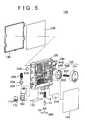
- Fig. 5 is an exploded perspective view of an ink cartridge.
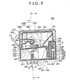
- Fig. 6 is a front view of an ink cartridge in a state before a film is attached.
- Fig. 7 is a front view of an ink cartridge in a state after a film is attached.
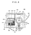
- Fig. 8 is a rear view of an ink cartridge in a state before a film is attached.
- Fig. 9 is an exploded perspective view of an ink supply controlling means.
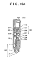
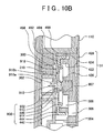
- Fig. 10A is a cross-sectional view that shows the A-A section of the ink cartridge
- Fig. 10B is an enlarged cross-sectional view near an ink supply controlling means.
- Fig. 11A shows a structure of an ink supply controlling means in a state where a valve is opened
- Fig. 11B shows a structure of an ink supply controlling means in a state where a valve is closed.
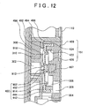
- Fig. 12 is a cross-sectional view of another embodiment of a membrane valve.
- Fig. 13A is a cross-sectional view of another embodiment of a membrane valve
- Fig. 13B is a cross-sectional view of another embodiment of a membrane valve.
- Fig. 1 is a front perspective view of the structure of the ink cartridge 100 used for an inkjet type recording apparatus, which is adapted for an example of a liquid cartridge suitable for supplying a liquid to a liquid ejecting head of a liquid ejecting apparatus, obliquely viewed from an upper position.
- the liquid ejecting apparatus of the present invention is not limited to the liquid ejecting head of the liquid ejecting apparatus, and it includes a color material ejecting head of the color filter manufacturing apparatus for manufacturing color filters of a liquid crystal display, an electrode material (conduction paste) ejecting head for forming electrodes such as an organic EL display or a FED (Field Emission Display) and further a bio organism ejecting head of the biochip manufacturing apparatus and a sample ejecting head as a minute pipette for manufacturing biochips.
- a color material ejecting head of the color filter manufacturing apparatus for manufacturing color filters of a liquid crystal display
- an electrode material (conduction paste) ejecting head for forming electrodes such as an organic EL display or a FED (Field Emission Display)
- bio organism ejecting head of the biochip manufacturing apparatus and a sample ejecting head as a minute pipette for manufacturing biochips.
- Fig. 2 and Fig. 3 are rear perspective views the ink cartridge 100 in Fig. 1 obliquely viewed from a lower position
- Fig. 2 shows the ink cartridge 100 in a state a film 110 is not attached thereto
- Fig. 3 shows the ink cartridge 100 in a state the film 110 is attached thereto.
- Fig. 4 and Fig. 5 are perspective views showing the ink cartridge 100 wherein members of which the ink cartridge 100 consist is exploded.
- Fig. 6 and Fig. 7 are front views of the ink cartridge 100 in Fig. 1
- Fig. 6 shows the ink cartridge 100 in a state before a film 130 is attached to an opening part 122 of the ink cartridge 100
- Fig. 7 shows the ink cartridge 100 in a state in which a film 130 is attached to an opening part 122 of the ink cartridge 100.
- the film 130 is attached to an area, which is shown with hatching in Fig. 7 .
- the ink cartridge 100 has a cartridge body (container body) 120 having a shape of an approximate case with the opening part 122, the film 130, which covers almost all face of the opening part 122 and a lid 140, which covers the outside of the film 130.
- the internal part of the cartridge body 120 is partitioned by ribs or walls as described below.
- the film 130 seals almost all face of the opening part 122 of the cartridge body 120 in order that the internal part of it comes into a closed state.
- the lid 140 is further fixed to the cartridge body 120 in order to wrap the outside of the film 130 in a non-closed state.
- the cartridge body 120 has an ink accommodating section 111 for containing ink, an ink channel part from the ink accommodating section 111 to an ink supplying part 160, an ink side passage, which allows the ink accommodating section 111 to communicate with the atmosphere, the atmospheric valve containing section and an atmosphere communicating part, which consists of an atmosphere passage, and it is made of, for example, Polypropylene (PP) in a unified body.
- PP Polypropylene
- the ink cartridge 100 further has an ink supply controlling means 150, a memory 170 and an engaging lever 180.
- the ink supplying part 160 supplies ink, which is contained in the ink accommodating section 111, to the recording head of the inkjet type recording apparatus through an ink supply needle of the apparatus which needle is inserted into an opening of said ink supplying part 160.
- the ink supply needle faces the lower face of the cartridge body 120 and is formed on the carriage 42 mounting thereon the ink cartridge 100.
- the memory 170 is caulked into an attaching part 190 and the attaching part is caulked and attached to the lower part of the side face of the cartridge body 120.
- the memory 170 stores the information on the kind of the ink cartridge 100, the information on the color held by the ink cartridge 100 and the information on the present amount of remaining ink etc., and it transfers this information by a plurality of terminals 171, which are exposed thereon, between the apparatus body and the ink cartridge 100.
- the engaging lever 180 is formed at the upper part of the side face opposite to the attaching part 190 in regard to the cartridge body 120, and is engaged with the holder of the inkjet type recording apparatus.
- An ink supply controlling means 150 consists of a pressure-difference valve, which supplies ink of the ink accommodating sectionlll to the ink supplying part 160 by pressure difference between ink accommodating section 111 and the ink supplying part 160 that occurs accompanying the consummation of ink.
- the ink supply controlling means has a membrane valve 900, which is an example of a valve member inserted into a pressure-difference regulating valve unit containing section 495 of the cartridge body 120, capable of elastic deformation, a valve lid 151 which covers the pressure-difference regulating valve unit containing section 495, a coil spring 907 which is an example of an urging member arranged between the membrane valve 900 and the valve lid 151.
- This membrane valve 900, the valve lid 151 and the coil spring 907 are an example of the pressure-difference regulating valve unit constituting the ink supplycontrollingmeans 150 of the present invention. Themethod of assembling the pressure-difference regulating valve unit and its operation will be described below.
- the ink accommodating section ill is divided by a wall 272 mainly into a upper part and a lower part, which extends in a horizontal direction, as shown in Fig. 6 and Fig. 7 , and an atmospheric side accommodating chamber 270, which can communicate with the ambient air through a communicating hole 242, is formed in the lower part, while a liquid-supply side accommodating chamber, which consists of a first ink accommodating section 292 and a second ink accommodating section 294 and is blocked from the ambient air, is formed in the upper part.
- the liquid-supply side accommodating chamber 290 is divided by a slope wall 271 having a communicating part 276 near the wall 272 (at the lower part area) into the first and second ink accommodating sections 292 and 294, and is provided with a channel part 296, which is arranged in order to surround the circumference of the second ink accommodating section 294.
- the channel part 296 is coupled with the second ink accommodating section 294 via a communicating part 278 at the lower part, and besides is coupled with the ink supply controlling means 150 via passages 298 and 300 and a passage hole 918.
- the lower flow side of the ink supply controlling means 150 is configured to communicate with the ink supplying part 160 via a passage hole 910 which communicates with the ink supply controlling means 150, a communicating part 302 and a channel 321 which communicate with the passage hole 910, a passage hole 323 which is formed at an end of the channel 321 and is formed to face the front face side and a communicating part 304 of which an end communicates with the passage hole 323.
- the atmospheric side accommodating chamber 270 and the first ink accommodating section 292 communicate with each other by a communicating passage 295 which extends vertically, and are configured in order that the ink in the atmospheric side accommodating chamber 270 is sucked up into the first ink accommodating section 292 corresponding to the consummation of ink from the ink supplying part 160 and then flows into the ink supply controlling means 150 via the second ink accommodating section 294 and the channel part 296 etc.
- the ink is flowed into the ink supply controlling means 150 from the atmospheric side accommodating chamber 270 of the ink accommodating section 111 through a sequence of the communicating part 274, a second ink inlet 162, a communicating passage 295, the communicating parts 276 and 278, the channel part 296, the passages 298 and 300 and the passage hole 918.
- the atmospheric valve part 250 has a hollowpart 232, whichis anatmospheric valve containing section, for containing an atmospheric valve 254, and has a communicating hole 239, also serving as a atmosphere communicating channel, of which the diameter is a little larger than that of a shaft part 264 of the atmospheric valve 254, on the wall face of a lower position of the hollow part 232, so that the shaft part 264 of the atmospheric valve 254 is always urged towards the bottom face of the ink cartridge 100 by a spring 255 and inserted thereto to be able to freely slide, and the communicating hole 239 is sealed by the atmospheric valve 254 when the ink cartridge 100 is not mounted onto the holder of the inkjet type recording apparatus.
- a hollowpart 232 whichis anatmospheric valve containing section, for containing an atmospheric valve 254, and has a communicating hole 239, also serving as a atmosphere communicating channel, of which the diameter is a little larger than that of a shaft part 264 of the atmospheric valve 254, on the wall face of a lower position
- Fig. 8 is a rear view showing the ink cartridge 100 of Fig. 1 in a state before the film 110 is attached thereto.
- the atmosphere side passage which communicates with the ambient air taking the communicating hole 239 described above as a boundary, consists of an opening 212, a passage 214 which is circuitous or winding, a filter containing section 216, a communicating hole 218, a communicating part 222 and a communicating hole 253 and a communicating part 224 which are formed on the bottom face of the communicating part 222.
- an end of one passage 214 which is formed on the front face of the cartridge body 120 and winding in the shape of a maze, is opened with the atmosphere by the opening 212, and the other end is coupled with the filter containing section 216 for containing the filter 215 ( Fig. 4 and Fig. 5 ) having a function of ink repellency and air permeability.
- the filter container part 216 communicates with the communicating hole 218, which penetrates from the front side to the rear side of the cartridge body 120.
- the communicating hole 218 is coupled with the communicating part 224 via the communicating part 222 and the communicating hole 253, which is formed on the bottom part of a room that partitions the communicating part 222, in the rear side of the cartridge body 120.
- a chamber 930 which consists of a concave part, is provided in the middle of the passage 214.
- the communicating part 224 is formed as a concave part 257 on the bottom face of the cartridge body 120, and a shaft part 264, which is an operating rod of the atmospheric valve 254, is exposed, while the communicating hole 239 capable of communicating with the hollow part 232, which contains the atmospheric valve 254, and the communicating hole 253, which communicates with the communicating part 222, are formed inside the concave part 257, and the external face of the concave part 257 is sealed by the film 132 for sealing the first and second ink inlets 161 and 162.
- a thing, which can perform elastic deformation by a pressing force of a projection protruding from the holder, is chosen for this film 132.
- the ink side passage which communicates with the atmospheric side accommodating chamber 270 taking the communicating hole 239 described above as a boundary, consists of an hollow part 232, a passage hole 234a, a communicating chamber 234b, a communicating part 234c, a communicating chamber 234d, a communicating part 236. a communicating chamber 237 and a communicating hole 238, a communicating groove 240 and a communicating hole 242.
- the passage hole 234a is formed on a wall of upper part of the hollow part 232, and the atmosphere passage is formed to communicate in the following sequence: the communicating chamber 234b via the passage hole 234a, the communicating part 234c formed by a not chon a wall of the upper part of the communicating chamber 234b, the communicating chamber 234d provided at the upper part of the communicating part 234c, the communicating part 236 formed by a notch of a wall of the upper part of the communicating chamber 234d and the communicating chamber 237 provided with the communicating hole 238 at a lower position.
- the ink supplying part 160 has a seal member 12, which is made of elastomer having an insertion opening 26 into which the ink supply needle provided in the holder is inserted, a supply valve 13, which closes the insertion opening 26 of the seal member 12 and an urging member, which consists of a coil spring etc. that urges the supply valve 13 towards the seal member 12.
- a film 604 is attached to the insertion opening 26 of the seal member 12 at the time of factory.
- the projecting part provided in the holder pushes up the shaft part 264 of the atmospheric valve upwardly via the film 132 and the ink supply needle of the holder pushes up the supply valve 13 of the ink supplying part 160 upwardly.
- the communicating hole 239 allows the atmosphere channel, extending from the atmospheric valve accommodating section 232 to the communicating hole 242, to communicate with the atmosphere.
- the upper flow than the supply valve 13 in regard to the ink supplying part 160 communicates with the ink supply needle.
- the ink supplying needle of the holder gets into the insertion opening 26 by tearing the film 604 attached to the insertion opening 26 of the ink cartridge 100.
- the recording head When the inkjet type recording apparatus begins to record in a state where the communicating hole 242 communicates with the atmosphere, the recording head is supplied with ink through the ink supply needle from the ink supplying part 160.
- the ink which is flowed in a sequence of an arrow a shown in Fig. 6 and the passage hole 918, from the ink accommodating section 111 to the ink supplying part 160, is flowed in a sequence of arrows b, c and d shown in Fig. 6 via the ink supply controlling means 150, is flowed into the ink supplying part 160 and is supplied to the ink supply needle inserted in the ink supplying part 160.
- the inkof the atmospheric side accommodating chamber 270 is supplied to the liquid-supply side accommodating chamber 290.
- the atmosphere accompanying the consummation of ink in the atmospheric side accommodating chamber 270 is flowed into the atmospheric side accommodating chamber 270 from the communicating hole 242 through a route in a sequence of an arrow f in Fig. 6 , the communicating part 224 of the bottom face and an arrow g.
- the channel which is coupled with the atmospheric side accommodating chamber 270 and the liquid-supply side accommodating chamber 290, is provided with a communicating opening at the lowest part of the atmospheric side accommodating chamber 270, so that the atmosphere is not flowed into the liquid-supply side accommodating chamber 290 until all of the ink in the atmospheric side accommodating chamber 270 is moved to the liquid-supply side accommodating chamber.
- the ink in the first and second ink accommodating sections292 and294 of the liquid-supply side accommodating chamber 290 is consumed in that sequence.
- the ink in the liquid-supply side accommodating chamber 290 is prevented from being flowed backward to the atmospheric side accommodating chamber 270.
- the air is flowed into the first ink accommodating section 292. Due to this, the liquid level of the first ink accommodating section 292 goes down, but the first and second ink accommodating sections 292 and 294 communicate by the communicating part 276 only at the lower part, so that the ink in the first ink accommodating section 292 is first consumed.
- the liquid level reaches the communicating part 276 because the ink in the first ink accommodating section 292 is consumed, the air is flowed into the second ink accommodating section 294 according to the consummation of ink in the second ink accommodating section 294.
- the ink in the atmospheric side accommodating chamber 270 and the first and second ink accommodating sections 292 and 294 is consumed in that sequence, the ink is supplied into the ink supplying part 160 through the passage hole 918 via the passage 300 from the communicating part 278, which is provided near the wall 272 that partitions the ink accommodating section into nearly two parts up and down, even though the liquid level of ink exists in any containing section.
- Fig. 9 is an exploded perspective view of an ink supply controlling means 150.
- Fig. 10A is a cross-sectional view that shows the section A-A of the ink cartridge 100 in regard to Fig. 6 .
- Fig. 10B is a partly enlarged cross-sectional view near the ink supply controlling means 150 in Fig. 10A .
- a membrane valve 900, a coil spring 907 and a valve lid 151, which constitute theinksupplycontrollingmeans150, are assembled tobe separated from the cartridge body 120 as a pressure-difference regulating valve unit.
- the membrane valve 900 has a peripheral edge part 442 of a cylindrical shape, a thick part 444 provided near the peripheral edge part 442, a body part 446 surrounded by the thick part 444 and elastically deformed, a valve lid side projecting part 902 projecting toward the valve lid 151 at the center of the body part 446, that is, at a position where the coil spring 907isincontactwiththebodypart446, abodypartsideprojecting part 913 projecting toward the passage hole 910 of a wall face 494 of a pressure-difference regulating valve unit containing section 495 and a bent part 914.
- the membrane valve 900 is integrally molded by using a material of elasticity softer than the cartridge body 120 such as elastomer.
- the valve lid side projecting part 902 is approximately cylindrical in shape, and the outer diameter of the cross-section is slightly larger than the inner diameter of the coil spring 907 in a state before the valve lid side projecting part 902 is assembled to the coil spring 907. Therefore, since the valve lid side projecting part 902 is inserted into an end of the coil spring 907, the coil spring 907 is held to be exactly positioned to the membrane valve 900. More over, only a part of the outer diameter of the cross-section of the valve lid side projecting part 902 may be larger than the inner diameter of the coil spring 907 and other part thereof may be small.
- the valve lid 151 has a membrane valve holding part 422, which is an example of a valve member holding part in the shape of an approximate cylinder, a wall face contact part 424 of an approximately cylindrical shape provided around the membrane valve holding part 422 and a spring fitting part 426 projecting toward the membrane valve 900 at the center of the cylinder shape, and is integrally molded by using, e. g., Polypropylene (PP) like the cartridge body 120.
- PP Polypropylene
- the spring fitting part 426 of the valve lid 151 is approximately cylindrical in shape, and its inner diameter is approximately the same as the outer diameter of the coil spring 907. Therefore, an end of the coil spring 907 is held to be exactly positioned to the valve lid 151.
- the spring fitting part 426 has a plurality of notches 427 (four in this embodiment shown in Fig. 9 ) cut in from a side at which the membrane valve 900 is provided.
- the spring fitting part 426 has the notches 427 enabling the ink to flow between the internal part and the external part, in a state where the membrane valve 900 is opened, if the valve lid side projecting part 902 of the membrane valve 900 is moved and stuck to a position where it gets into the spring fitting part 426 of the valve lid 151, and thus it is possible to prevent the passage inside the spring fitting part 426 from being closed.
- the lengths of a plurality of projecting pieces in a surface direction formed by these notches 427 are larger than the inner diameter of the coil spring 907. Therefore, if the coil spring 907 is attached into the spring fitting part 426, it is possible to prevent the projecting pieces of the spring fitting part 426 from being got into the coil spring 907 by mistake.
- the outer diameter of an approximately cylindrical shape of the membrane valve holding part 422 in regard to the valve lid 151 is slightly larger than the inner diameter of the peripheral edge part 442 of the membrane valve 900, in a state before the peripheral edge part 442 of the membrane valve 900 is assembled.
- the inner diameter of the wall face contact part 424 in regard to the valve lid 151 is larger than the outer diameter of the peripheral edge part 442 of the membrane valve 900.
- the peripheral edge part 442 of the membrane valve 900 is inserted between the membrane valve holding part 422 and the wall face contact part 424 of the valve lid 151, so that the membrane valve holding part 422 urges the peripheral edge part 442 toward a direction to expand it from the inside, and thus the membrane valve 900 is held in the valve lid 151.
- the pressure-difference regulating valve unit is formed.
- only a part of the outer diameter of the membrane valve holding part 422 of the valve lid 151 may be larger than the inner diameter of the peripheral edge part 442 and other part may be small, in a state before the peripheral edge part 442 of the membrane valve 900 is assembled into the membrane valve holding part 422.
- the valve lid 151 further has the communicating part 306 that penetrates from a position where the membrane valve 900 is attached to a position where the film 110 is attached. Due to this, if the valve lid 151 is attached to the cartridge body 120 along with the membrane valve 900, the membrane valve chamber 308 that consists of the valve lid 151 and the membrane valve 900 communicates with the communicating part 304 and the inksupplyingpart160viathecommunicatingpart306. Inaddition, the communicating part 304 also communicates with the communicating part 302 provided directly downstream of the passage hole 910.
- a circular projection 492 in the shape of a ring is provided on the wall face 494 of the pressure-difference regulating valve unit containing section 495 of the cartridge body 120 along the outer circumference surrounding the passage holes 910 and 918, from the view of the pressure-difference regulating valve unit containing section 495 side (from the right in Fig. 10B ).
- the circular projection 492 is the shape of a wedge that projects toward a direction to which the membrane valve 900 is attached and its cross-section shown in Fig. 10B is sharp toward the direction to which the membrane valve 900 is attached.
- the thick part 444 of the membrane valve 900 is softer than the circular projection 492 .
- the circular projection 492 is provided to face the membrane valve holding part 422 of the valve lid 151 holding the thick part 444 of the membrane valve 900. Due to this, the membrane valve holding part 422 of the valve lid 151 is in contact with the thick part 444 and pushes the thick part 444 toward the circular projection 492.
- the membrane valve 900 seals the surrounding of the communicating passage 496 securely. That is, the membrane valve holding part 422 is also functioning as a valve member contact part in regard to the present invention.
- the inner peripheral wall 498 forming the pressure-difference regulating valve unit containing section 495 and the outer circumference of the wall face contact part 424 of the valve lid 151 are approximately the same in shape.
- the distance between the membrane valve holding part 422 of the valve lid 151 and the wall face 494 when the wall face contact part 424 of the valve lid 151 is in contact with the wall face 494 is slightly smaller than the sum of the height from the wall face 494 to the tip of the circular projection 492 and the thickness of the thick part 444 of the membrane valve 900. Therefore, the surface 428 outside the valve lid 151 projects slightly more than a wall face of the cartridge body 120 in regard to the surrounding of the valve lid 151.
- the film 110 is attached to cover the surface 428 outside the valve lid 151 and a wall face of the cartridge body 120 and to urge a surface of the outside of the valve lid 151. Due to this, the film 110 urges the valve lid 151 toward the pressure-difference regulating valve unit containing section 495. Therefore, the valve lid 151 is attached to the pressure-difference regulating valve unit containing section 495 securely, and it is possible to improve sealing property between the circular projection 492 and the membrane valve 900. In addition, the dust does not occur because it is unnecessary to use ultrasonic welding, and thus it is possible to prevent the dust from being mixed into the ink.
- the passage hole projecting part 910b is provided around the passage hole 910 of the cartridge body 120 to project toward the membrane valve 900 and be in contact with the body part side projecting part 913 of the membrane valve 900.
- the body part side projecting part 913 of the membrane valve 900 is in contact with the passage hole projecting part 910b when the ink is not supplied, so that it is possible to close the passage hole 910 securely.
- a filter 310 is provided at the communicating part 300 of the cartridge body 120.
- the filter 310 filters foreign substances contained in the ink supplied to the inkjet type recording apparatus through the communicating part 300.
- the filter 310 is provided directly upstream of the ink supply controlling means 150, and thus the ink passing the filter 310 is flowed into the ink supply controlling means 150 directly.
- the membrane valve 900 and the coil spring 907 are held in the valve lid 151 to form thepressure-differenceregulatingvalveunit,itisnot necessary to a use fixture to attach the coil spring 907 to the cartridge body 120 and it is possible to attach it easily. Further, the valve lid 151 and the pressure-difference regulating valve unit containing section 495 are positioned in a state where the membrane valve 900 is held in the valve lid 151, it is also possible to position the membrane valve 900 to the pressure-difference regulating valve unit containing section 495 with more high accuracy.
- Fig. 11A and 11B show a structure of the ink supply controlling means 150 of the ink cartridge 100 shown in Fig. 10A and 10B simply.
- Fig. 11A and 11B simply show a structure of the ink supply controlling means 150 described above in both states where the valve is opened and closed, and the configurations similar to those in Fig. 10A and 10B have the same symbols.
- the pressure of the ink supplying part 160 is decreased, and the pressure of the membrane valve chamber 308 is decreased via the communicating parts 304 and 306. Therefore, the pressure of the overall membrane valve chamber 308 side in regard to the membrane valve 900 is decreased. Meanwhile, although the pressure near the passage hole 910 via the communicating part 302 in regard to a surface of the communicating passage 496 side in regard to the membrane valve 900 is decreased, the pressure around the passage hole 910 is not decreased.
- the body part side proj ectingpart 913 of the membranevalve 900 is separated from the passage hole projecting part 910b so that the passage hole 910 opens.
- the ink flows in a sequence of the communicating part 300, the passage hole 918, the communicating passage 496 and the communicating part 302 and 304, and is supplied to the recording head from the ink supplying part 160 (the arrow b in Fig. 11B ).
- the ink flows via only the communicating passage 496 side of the membrane valve 900, and thus though bubbles held up in the communicating part 300 are got in, they flow into the recording head along with the stream of the ink. Therefore, these bubbles do not get into the membrane valve chamber 308.
- the pressure change of the ink supplying part 160 side affects the membrane valve 900 securely, and it is possible to supply the ink of the ink accommodating section 111 to the recording head without fail.
- the bubbles flow into the recording head, it is possible to eliminate the bubbles easily by discharging the ink compulsorily by applying the negative pressure to the recording head.
- the passage hole 910 has an expanding part 910a that expands gradually toward the communicating part 302.
- the passage resistance of the ink flowing into the communicating part 302, of which the cross-section area is larger than the passage hole 910 through the passage hole 910 becomes small.
- the membrane valve 900 is too thin so that it is difficult to provide the expanding part at the passage hole, and thus it is impossible decrease the passage resistance of the ink flowing through the passage hole. Therefore, in the present embodiment, it is possible to decrease the passage resistance of the ink passing the passage hole 910 in contrast to the case the passage hole is provide at the membrane valve 900 side.
- the ink is supplied to the membrane valve chamber 308 and the ink supplying part 160 via the communicating part 302 in the opened state, the pressure difference between the membrane valve chamber 308 and the communicating part 300 is eliminated.
- the body part side projecting part 913 of the membrane valve 900 closes the passage hole 910 by being repelled by the urging force of the coil spring 907, and blocks the communicating passage 496.
- the valve lid side projecting part 902 of the membrane valve 900 is the shape of a cylinder, and the outer shape or diameter of the cross-section is slightly larger than the inner diameter of the coil spring 907.
- the configuration of the valve lid side projecting part 902 is not limited to this.
- the membrane valve 900 may project toward the valve lid 151 in regard to the center part, and may have a valve lid side cylinder part of a cylindrical shape of which a part of the inner diameter is smaller than the outer diameter of the coil spring 907.
- the coil spring 907 is inserted into the valve lid side cylinder part, so that the coil spring 907 is engaged with the membrane valve 900. Accordingly, the coil spring 907 can be engaged to be positioned to the membrane valve 900 accurately.
- the membrane valve 900 shown in Fig. 10A and 10B closes the passage hole 910 with the urging force of the coil spring 907 by the body part side projecting part 913 that projects toward an opposite side to the coil spring 907.
- the configuration to close the passage hole 910 is not limited to this.
- Fig. 12 is a cross-sectional view of another embodiment of a membrane valve 450 corresponding to that in Fig. 10B .
- the configurations in Fig. 12 similar to those in Fig. 10B are given the same reference number, and the description of them will be omitted.
- the membrane valve 450 shown in Fig. 12 has a seal part 452 that projects toward an opposite side to the coil spring 907.
- the seal part 452 corresponds to a position where it is urged by the coil spring 907 and is provided to be circular to surround the passage hole 910.
- the circular projection 492 of the cartridge body 120 is pressed to be in contact with the membrane valve 450, and thus it is possible to attach the membrane valve 450 to the cartridge body 120 without the dust that occurs during attaching by ultrasonic welding.
- the membrane valve 450 and the coil spring 907 are held in the valve lid 151 so that the pressure-difference regulating valve unit can be formed, it is easy to position them each other.
- the coil spring 907 is held between the membrane valve 450 and the valve lid 151, and thus a fixture for attaching the coil spring 907 to the cartridge body 120 is not needed. Therefore, it is possible to attach them easily.
- the passage hole 910 is formed at the center part in regard to the wall face 494 of the pressure-difference regulating valve unit containing section 495, and thus the membrane valve 450 of the ink supply controlling means 150 is moved corresponding to the pressure of the ink supplying part 160 side to close the passage hole 910.
- the shape of the membrane valve 450 is not limited.
- Fig. 13A and 13B the configurations similar to the ink cartridge 100 shown in Fig. 10B are given the same reference number, and the description of them will be omitted.
- one passage hole 918 is provided at an area except the center area in regard to the wall face 494 of the pressure-difference regulating valve unit containing section 495, and a projecting part 990 is provided at the center part.
- a communicating hole 992 that is in elastically contact with the projecting part 990 is formed at the center of a membrane valve 900' of the ink supply controlling means 150.
- the membrane valve 900' is pressed by the coil spring 907 toward the projecting part 990 of the pressure-difference regulating valve unit containing section 495 so that the communicating hole 992 of the membrane valve 900' is sealed.
- the membrane valve 900' is separated from the projecting part 990 against the coil spring 907, and the ink acts similar to the embodiment shown in Fig. 10B via the communicating hole 992 of the membrane valve 900' along the passage shown by an arrow b' in the drawing.
- the pressure-difference regulating valve unit containing section 495 is formed on an outer surface of the cartridge body 120, but the pressure-difference regulating valve unit containing section may be form at the ink supplying part 160 to contain the pressure-difference regulating valve unit as a concave part.
Landscapes
- Ink Jet (AREA)
- Feeding And Controlling Fuel (AREA)
- Containers And Packaging Bodies Having A Special Means To Remove Contents (AREA)
Abstract
Description
- The present invention relates to a pressure-difference regulating valve unit, a liquid cartridge and a method for assembling a liquid cartridge. More particularly, the present invention relates to a pressure-difference regulating valve unit, a liquid cartridge and a method for assembling a liquid cartridge, wherein the liquid cartridge supplies a liquid to a liquid ejecting apparatus when mounted on the liquid ejecting apparatus.
- In an inkjet type recording apparatus, ink is supplied to a recording head while mounting an ink cartridge containing the inkonaholderof an inkjet type recording apparatus. Here, the ink, the inkjet type recording apparatus and the ink cartridge are an example of the liquid, the liquid ejecting apparatus and liquid cartridge respectively.
- The ink cartridge is provided with, for example, an ink accommodating section for containing the ink, a valve member that operates based on the pressure difference between the ink accommodating section side and the recording head side and an atmospheric valve for connecting the ink accommodating Section with the atmosphere. This ink cartridge is mounted on a holder of an inkjet type recording apparatus, and thus the atmospheric valve allows the ink accommodating section to be connected with the atmosphere. Further, in the state where the ink cartridge is mounted on the holder, the pressure difference occurs in the valve member because the recording head consumes the ink, so that a center part of the valve member is elastically deformed by the pressure difference, and thus the ink is supplied to the recording head from the ink accommodating section as disclosed in
Japanese Patent Application Publication No. 1999-170558 - In the ink cartridge above, the valve member has a peripheral edge part with the difficulty to be elastically deformed in contrast to the center part, and the peripheral edge part is fixed to the ink cartridge by ultrasonic welding. Therefore, there was a problem that the dust caused by ultrasonic welding was mixed into the ink.
Similar ink cartridges are known fromJP-A-2002-205413 EP-A-1258359 as well asJP-A-11-170 558 DE 103 18 949 A1 , the applicant has voluntary limited the scope of the present application and submitted separate claims for Germany both disclosing the features of the preamble of claim 1. - It is an object of the present invention to provide a pressure-difference regulating valve unit, a liquid cartridge and a method for assembling a liquid cartridge, which is capable of overcoming the above drawbacks accompanying the conventional art. The above and other objects can be achieved by combinations described in the independent claims. The dependent claims define further advantageous and exemplary combinations of the present invention.
This object is solved by the subject matter as defined in claim 1. Embodiments of the present invention are named in the dependent claims. - According to the first aspect of the present invention, a liquid cartridge comprises a liquid containing section for containing a liquid, a cartridge body which comprises a liquid supplying part for supplying a liquid in the liquid containing section outside, a valve member contained in a concave part formed at the cartridge body to be opened when a pressure difference between the liquid containing section and the liquid supplying part occurs and a valve lid for holding the valve member while fitting into the concave part and besides pressing an outer circumference of the valve member toward a wall face in the concave part, wherein a projection is formed on a surface, with which the valve member is in contact, of the wall face of the concave part to be in pressure contact with the valve member along the outer circumference of the valve member.
- Thus, since the projection of the wall face in the concave part is in pressure contact with the valve member so that the valve member is attached to the cartridge body, it is possible to attach the valve member easily by the valve member and the projection without ultrasonic welding. In addition, since the ultrasonic welding is not needed, the dust resulting from that does not occur, so that it is not necessary to clean the dust and it is possible to prevent the dust from being mixed into the ink.
- In the liquid cartridge above, the valve lid may include a valve member contact part provided to face the projection holding the valve member for pressing the valve member toward the projection while being in contact with the valve member.
- Thus, the contact part can attach the valve member to the projection securely.
- The liquid cartridge above may further include a seal member for sealing to urge an outer surface opposite to a surface, on which the valve member is provided, of the valve lid and a wall face of the cartridge body around the outer surface of the valve lid toward a direction in which the valve lid is in contact with the projection, wherein the concave part is formed on the wall face of the cartridge body.
- Thus, since the seal member attaches the valve lid to the wall face side, the valve lid is attached to the wall face more securely, and it is possible to improve the liquidtight property between the projection and the valve member.
- In the liquid cartridge above, the valve member may be formed of an elastic material, and the projection is inpressure contact, deforming the valve member. Thus, it is possible to attach the valve member easily by the valve member and the projection securely without ultrasonic welding.
- According to the second aspect of the present invention, a pressure-difference regulating valve unit, which comprises a liquid containing section for containing a liquid and a valve member contained in a cartridge body comprising a liquid supplying part for supplying a liquid in the liquid containing section outside, to be opened when a pressure difference between the liquid containing section and the liquid supplying part occurs, comprises a valve lid which comprises the valve member comprising a peripheral edge part of a cylindrical shape elastically deformable based on the pressure difference and a valve member holding part of a substantially cylindrical shape for fixing the peripheral edge part by inserting into the peripheral edge part of the valve member and an urging member provided between the valve member and the valve lid for urging the valve member toward a direction being distanced from the valve lid.
- Thus, since the valve member and the urging member are held in the valve lid so that the pressure-difference regulating valve unit is formed, it is easy to position them each other. In addition, since the urging member is held between the valve member and the valve lid, a fixture for attaching the urging member to the liquid cartridge is not needed. Therefore, it is possible to assemble the liquid cartridge easily.
- In the pressure-difference regulating valve unit, the valve lid may further include a wall surface contact part of a substantially cylindrical shape, of which an inner diameter is larger than an outer diameter of the peripheral edge part of the valve member, surrounding the valve member holding part, being in contact with a wall face of a concave part formed at the cartridge body to which the valve lid is attached.
- Thus, the valve member is securely held on the wall face of the concave part. Further, since the valve lid and the cartridge body are positioned, it is also possible to position the valve member to the cartridge body with high accuracy.
- In the pressure-difference regulating valve unit, the urging member may be a coil spring, the valve lid may include a spring fitting part of a cylindrical shape, of which an inner diameter is substantially the same as an outer diameter of the coil spring, projecting to face the valve member at a position on which the coil spring is in contact, and the coil spring may be held in the valve lid while fitting into the spring fitting part.
- Thus, the coil spring is positioned to the valve lid accurately, so that it is possible to urging the valve member securely.
- In the pressure-difference regulating valve unit, the spring fitting part may have a notch enabling a liquid to flow into and/or out of the spring fitting part, even though the valve member is attached to the spring fitting part.
- Thus, if the liquid passage is in the spring fitting part, it is possible to prevent the passage in the spring fitting part from closing, even though the valve member is moved toward the valve lid by the pressure difference to attach the valve member to the spring fitting part.
- In the pressure-difference regulating valve unit, the spring fitting part may have a plurality of notches cut in from the valve member, and at least one of lengths of a plurality of projecting pieces in a surface direction formed by the plurality of notches may be larger than an inner diameter of the coil spring.
- Thus, if the coil spring is attached to the spring fitting part of the valve lid, it is possible to prevent the spring fitting part from getting into the coil spring be mistake.
- In the pressure-difference regulating valve unit, the urging member may be a coil spring, the valve member may include a valve lid side projecting part of a substantially cylindrical shape, of which at least a part of an outer diameter is larger than an inner diameter of the coil spring, projecting to face the valve lid at a position on which the coil spring is in contact, and the coil spring may be held in the valve member by inserting the valve lid side projecting part into the coil spring.
- Thus, it is possible to hold the coil spring to be positioned to the valve member accurately.
- In the pressure-difference regulating valve unit, the urging member may be a coil spring, the valve member may include a valve lid side projecting part of a substantially cylindrical shape, of which at least a part of an outer diameter is larger than an inner diameter of the coil spring, projecting to face the valve lid at a position on which the coil spring is in contact, and the coil spring may be held in the valve lid while fitting into the valve lid side cylinder part.
- Thus, it is possible to hold the coil spring to be positioned to the valve member accurately.
- In the pressure-difference regulating valve unit, the valve member may include a seal part provided to project toward an opposite side to the urging member corresponding to a posit ion at which the valve member is urged by the urging member, for preventing the liquid containing section and the liquid supplying part from communicating with each other by being urged by the urging member toward a wall face side of a concave part formed at the cartridge body.
- Thus, the seal part canprevent the liquid containing section and the liquid supplying part from communicating with each other by receiving the urging force from the urging member directly.
- According to the third aspect of the present invention, a method for manufacturing a liquid cartridge, which includes a liquid containing section for containing a liquid, a cartridge body including a liquid supplying part for supplying the liquid in the liquid containing section outside and a pressure-difference regulating valve unit including a valve member contained in the cartridge body to be opened when a pressure difference between the liquid containing section and the liquid supplying part occurs, includes the steps of preparing the cartridge body comprising the liquid containing section and a pressure-difference regulating valve unit containing section, which is a concave part formed at the cartridge body, communicating with the liquid containing section, forming a pressure-difference regulating valve unit by putting an urging member, which urges the valve member toward a direction being distanced from the valve lid, between the valve member comprising a peripheral edge part, of which a peripheral edge is cylindrical in shape, elastically deformable based on the pressure difference and a valve lid comprising a valve member holding part of a substantially cylindrical shape for fixing the peripheral edge part by inserting into the peripheral edge part of the valve member and attaching the pressure-difference regulating valve unit to the pressure-difference regulating valve unit containing section.
- Thus, the valve member, the urging member and the valve lid are assembled as the pressure-difference regulating valve unit, and then the pressure-difference regulating valve unit is attached to the liquid cartridge. Therefore, since the urging member is held between the valve member and the valve lid, a fixture for attaching the urging member to the liquid cartridge is not needed. Therefore, it is possible to assemble the liquid cartridge easily.
- The method for manufacturing a liquid cartridge may further include a step of sealing by a sealing member to cover an outer surface opposite to a surface, on which the valve member is provided, of the valve lid and a wall face of the cartridge body around the outer surface of the valve lid toward a direction in which the valve lid is in contact with the projection, wherein the concave part is formed on the wall face of the cartridge body.
- Thus, since the seal member pushes the valve lid toward the wall face of the concave part, the valve lid is attached securely.
- The attaching step may include a step of forcing a projection to be in pressure contact with the valve member, wherein the projection may be provided along an outer circumference of the valve member on a wall face with which the valve member of the pressure-difference regulating valve unit containing section is in contact.
- Thus, since the projection of the wall face, with which the valve member of the pressure-difference regulating valve unit containing section is in contact, is in pressure contact with the valve member so that the valve member is attached to the cartridge body, it is unnecessary to attach the valve member by ultrasonic welding. Therefore, the dust caused by the ultrasonic welding does not occur, and it is possible to prevent the dust from being mixed into the ink.
- The summary of the invention does not necessarily describe all necessary features of the present invention. The present invention may also be a sub-combination of the features described above. The above and other features and advantages of the present invention will become more apparent from the following description of the embodiments taken in conjunction with the accompanying drawings.
-
Fig. 1 is a front perspective view of an ink cartridge. -
Fig. 2 is a rear perspective view of an ink cartridge before a film is attached. -
Fig. 3 is a rear perspective view of an ink cartridge after a film is attached. -
Fig. 4 is an exploded perspective view of an ink cartridge. -
Fig. 5 is an exploded perspective view of an ink cartridge. -
Fig. 6 is a front view of an ink cartridge in a state before a film is attached. -
Fig. 7 is a front view of an ink cartridge in a state after a film is attached. -
Fig. 8 is a rear view of an ink cartridge in a state before a film is attached. -
Fig. 9 is an exploded perspective view of an ink supply controlling means. -
Fig. 10A is a cross-sectional view that shows the A-A section of the ink cartridge, andFig. 10B is an enlarged cross-sectional view near an ink supply controlling means. -
Fig. 11A shows a structure of an ink supply controlling means in a state where a valve is opened, andFig. 11B shows a structure of an ink supply controlling means in a state where a valve is closed. -
Fig. 12 is a cross-sectional view of another embodiment of a membrane valve. -
Fig. 13A is a cross-sectional view of another embodiment of a membrane valve, andFig. 13B is a cross-sectional view of another embodiment of a membrane valve. - The invention will now be described based on the preferred embodiments, which do not intend to limit the scope of the present invention, but exemplify the invention. All of the features and the combinations thereof described in the embodiment are not necessarily essential to the invention.
-
Fig. 1 is a front perspective view of the structure of theink cartridge 100 used for an inkjet type recording apparatus, which is adapted for an example of a liquid cartridge suitable for supplying a liquid to a liquid ejecting head of a liquid ejecting apparatus, obliquely viewed from an upper position. - In addition, the liquid ejecting apparatus of the present invention is not limited to the liquid ejecting head of the liquid ejecting apparatus, and it includes a color material ejecting head of the color filter manufacturing apparatus for manufacturing color filters of a liquid crystal display, an electrode material (conduction paste) ejecting head for forming electrodes such as an organic EL display or a FED (Field Emission Display) and further a bio organism ejecting head of the biochip manufacturing apparatus and a sample ejecting head as a minute pipette for manufacturing biochips.
-
Fig. 2 andFig. 3 are rear perspective views theink cartridge 100 inFig. 1 obliquely viewed from a lower position,Fig. 2 shows theink cartridge 100 in a state afilm 110 is not attached thereto andFig. 3 shows theink cartridge 100 in a state thefilm 110 is attached thereto. Further,Fig. 4 andFig. 5 are perspective views showing theink cartridge 100 wherein members of which theink cartridge 100 consist is exploded.Fig. 6 andFig. 7 are front views of theink cartridge 100 inFig. 1 ,Fig. 6 shows theink cartridge 100 in a state before afilm 130 is attached to anopening part 122 of theink cartridge 100 andFig. 7 shows theink cartridge 100 in a state in which afilm 130 is attached to anopening part 122 of theink cartridge 100. In addition, thefilm 130 is attached to an area, which is shown with hatching inFig. 7 . - As shown in
Fig. 4 , theink cartridge 100 has a cartridge body (container body) 120 having a shape of an approximate case with theopening part 122, thefilm 130, which covers almost all face of theopening part 122 and alid 140, which covers the outside of thefilm 130. The internal part of thecartridge body 120 is partitioned by ribs or walls as described below. Thefilm 130 seals almost all face of theopening part 122 of thecartridge body 120 in order that the internal part of it comes into a closed state. Thelid 140 is further fixed to thecartridge body 120 in order to wrap the outside of thefilm 130 in a non-closed state. - The
cartridge body 120 has an inkaccommodating section 111 for containing ink, an ink channel part from theink accommodating section 111 to anink supplying part 160, an ink side passage, which allows theink accommodating section 111 to communicate with the atmosphere, the atmospheric valve containing section and an atmosphere communicating part, which consists of an atmosphere passage, and it is made of, for example, Polypropylene (PP) in a unified body. - The
ink cartridge 100 further has an ink supply controlling means 150, amemory 170 and an engaginglever 180. Theink supplying part 160 supplies ink, which is contained in theink accommodating section 111, to the recording head of the inkjet type recording apparatus through an ink supply needle of the apparatus which needle is inserted into an opening of saidink supplying part 160. The ink supply needle faces the lower face of thecartridge body 120 and is formed on the carriage 42 mounting thereon theink cartridge 100. Thememory 170 is caulked into an attachingpart 190 and the attaching part is caulked and attached to the lower part of the side face of thecartridge body 120. Thememory 170 stores the information on the kind of theink cartridge 100, the information on the color held by theink cartridge 100 and the information on the present amount of remaining ink etc., and it transfers this information by a plurality ofterminals 171, which are exposed thereon, between the apparatus body and theink cartridge 100. The engaginglever 180 is formed at the upper part of the side face opposite to the attachingpart 190 in regard to thecartridge body 120, and is engaged with the holder of the inkjet type recording apparatus. - An ink supply controlling means 150 consists of a pressure-difference valve, which supplies ink of the ink accommodating sectionlll to the
ink supplying part 160 by pressure difference betweenink accommodating section 111 and theink supplying part 160 that occurs accompanying the consummation of ink. The ink supply controlling means has amembrane valve 900, which is an example of a valve member inserted into a pressure-difference regulating valveunit containing section 495 of thecartridge body 120, capable of elastic deformation, avalve lid 151 which covers the pressure-difference regulating valveunit containing section 495, acoil spring 907 which is an example of an urging member arranged between themembrane valve 900 and thevalve lid 151. Thismembrane valve 900, thevalve lid 151 and thecoil spring 907 are an example of the pressure-difference regulating valve unit constituting the ink supplycontrollingmeans 150 of the present invention. Themethod of assembling the pressure-difference regulating valve unit and its operation will be described below. - The ink accommodating section ill is divided by a
wall 272 mainly into a upper part and a lower part, which extends in a horizontal direction, as shown inFig. 6 andFig. 7 , and an atmosphericside accommodating chamber 270, which can communicate with the ambient air through a communicatinghole 242, is formed in the lower part, while a liquid-supply side accommodating chamber, which consists of a firstink accommodating section 292 and a secondink accommodating section 294 and is blocked from the ambient air, is formed in the upper part. The liquid-supplyside accommodating chamber 290 is divided by aslope wall 271 having a communicatingpart 276 near the wall 272 (at the lower part area) into the first and secondink accommodating sections channel part 296, which is arranged in order to surround the circumference of the secondink accommodating section 294. Thechannel part 296 is coupled with the secondink accommodating section 294 via a communicatingpart 278 at the lower part, and besides is coupled with the ink supply controlling means 150 viapassages passage hole 918. - Moreover, the lower flow side of the ink supply controlling means 150 is configured to communicate with the
ink supplying part 160 via apassage hole 910 which communicates with the ink supply controlling means 150, a communicatingpart 302 and achannel 321 which communicate with thepassage hole 910, apassage hole 323 which is formed at an end of thechannel 321 and is formed to face the front face side and a communicatingpart 304 of which an end communicates with thepassage hole 323. - The atmospheric
side accommodating chamber 270 and the firstink accommodating section 292 communicate with each other by a communicatingpassage 295 which extends vertically, and are configured in order that the ink in the atmosphericside accommodating chamber 270 is sucked up into the firstink accommodating section 292 corresponding to the consummation of ink from theink supplying part 160 and then flows into the ink supply controlling means 150 via the secondink accommodating section 294 and thechannel part 296 etc. The ink is flowed into the ink supply controlling means 150 from the atmosphericside accommodating chamber 270 of theink accommodating section 111 through a sequence of the communicatingpart 274, asecond ink inlet 162, a communicatingpassage 295, the communicatingparts channel part 296, thepassages passage hole 918. - Meanwhile, the
atmospheric valve part 250 has ahollowpart 232, whichis anatmospheric valve containing section, for containing anatmospheric valve 254, and has a communicatinghole 239, also serving as a atmosphere communicating channel, of which the diameter is a little larger than that of ashaft part 264 of theatmospheric valve 254, on the wall face of a lower position of thehollow part 232, so that theshaft part 264 of theatmospheric valve 254 is always urged towards the bottom face of theink cartridge 100 by aspring 255 and inserted thereto to be able to freely slide, and the communicatinghole 239 is sealed by theatmospheric valve 254 when theink cartridge 100 is not mounted onto the holder of the inkjet type recording apparatus. -
Fig. 8 is a rear view showing theink cartridge 100 ofFig. 1 in a state before thefilm 110 is attached thereto. The atmosphere side passage, which communicates with the ambient air taking the communicatinghole 239 described above as a boundary, consists of anopening 212, apassage 214 which is circuitous or winding, afilter containing section 216, a communicatinghole 218, a communicatingpart 222 and a communicatinghole 253 and a communicatingpart 224 which are formed on the bottom face of the communicatingpart 222. - Particularly, as shown in
Fig. 8 , an end of onepassage 214, which is formed on the front face of thecartridge body 120 and winding in the shape of a maze, is opened with the atmosphere by theopening 212, and the other end is coupled with thefilter containing section 216 for containing the filter 215 (Fig. 4 andFig. 5 ) having a function of ink repellency and air permeability. Thefilter container part 216 communicates with the communicatinghole 218, which penetrates from the front side to the rear side of thecartridge body 120. The communicatinghole 218 is coupled with the communicatingpart 224 via the communicatingpart 222 and the communicatinghole 253, which is formed on the bottom part of a room that partitions the communicatingpart 222, in the rear side of thecartridge body 120. In the middle of thepassage 214, achamber 930, which consists of a concave part, is provided. - As shown in
Fig. 2 , the communicatingpart 224 is formed as aconcave part 257 on the bottom face of thecartridge body 120, and ashaft part 264, which is an operating rod of theatmospheric valve 254, is exposed, while the communicatinghole 239 capable of communicating with thehollow part 232, which contains theatmospheric valve 254, and the communicatinghole 253, which communicates with the communicatingpart 222, are formed inside theconcave part 257, and the external face of theconcave part 257 is sealed by thefilm 132 for sealing the first andsecond ink inlets film 132. - Meanwhile, as shown in
Fig. 6 , the ink side passage, which communicates with the atmosphericside accommodating chamber 270 taking the communicatinghole 239 described above as a boundary, consists of anhollow part 232, apassage hole 234a, a communicatingchamber 234b, a communicatingpart 234c, a communicatingchamber 234d, a communicatingpart 236. a communicatingchamber 237 and a communicatinghole 238, a communicatinggroove 240 and a communicatinghole 242. Particularly, thepassage hole 234a is formed on a wall of upper part of thehollow part 232, and the atmosphere passage is formed to communicate in the following sequence: the communicatingchamber 234b via thepassage hole 234a, the communicatingpart 234c formed by a not chon a wall of the upper part of the communicatingchamber 234b, the communicatingchamber 234d provided at the upper part of the communicatingpart 234c, the communicatingpart 236 formed by a notch of a wall of the upper part of the communicatingchamber 234d and the communicatingchamber 237 provided with the communicatinghole 238 at a lower position. - The communicating
hole 238, which penetrates from the rear side to front side of thecartridge body 120, communicates with the atmosphericside accommodating chamber 270 via the communicatinggroove 240, which communicates with the communicatinghole 238, and the communicatinghole 242, which communicates with the communicatinggroove 240 and also penetrates from the front side to the rear side of thecartridge body 120. - These the atmospheric
side accommodating chamber 270, the liquid-supplyside accommodating chamber 290, theatmospheric valve part 250 and the atmosphere side passage and the ink side passage become an area which is separated from the atmosphere by attaching thefilms - The
ink supplying part 160 has aseal member 12, which is made of elastomer having aninsertion opening 26 into which the ink supply needle provided in the holder is inserted, asupply valve 13, which closes theinsertion opening 26 of theseal member 12 and an urging member, which consists of a coil spring etc. that urges thesupply valve 13 towards theseal member 12. In addition, afilm 604 is attached to theinsertion opening 26 of theseal member 12 at the time of factory. - When the
ink cartridge 100 is mounted on the holder of the inkjet type recording apparatus, the projecting part provided in the holder pushes up theshaft part 264 of the atmospheric valve upwardly via thefilm 132 and the ink supply needle of the holder pushes up thesupply valve 13 of theink supplying part 160 upwardly. Due to this, the communicatinghole 239 allows the atmosphere channel, extending from the atmosphericvalve accommodating section 232 to the communicatinghole 242, to communicate with the atmosphere. And, the upper flow than thesupply valve 13 in regard to theink supplying part 160 communicates with the ink supply needle. In addition, if theink cartridge 100 is mounted on the holder for the first time after the shipment from the factory, the ink supplying needle of the holder gets into theinsertion opening 26 by tearing thefilm 604 attached to theinsertion opening 26 of theink cartridge 100. - When the inkjet type recording apparatus begins to record in a state where the communicating
hole 242 communicates with the atmosphere, the recording head is supplied with ink through the ink supply needle from theink supplying part 160. When ink is supplied from theink supplying part 160, the ink, which is flowed in a sequence of an arrow a shown inFig. 6 and thepassage hole 918, from theink accommodating section 111 to theink supplying part 160, is flowed in a sequence of arrows b, c and d shown inFig. 6 via the ink supply controlling means 150, is flowed into theink supplying part 160 and is supplied to the ink supply needle inserted in theink supplying part 160. - According to this flowofink, in the
ink accommodating section 111, the inkof the atmosphericside accommodating chamber 270 is supplied to the liquid-supplyside accommodating chamber 290. The atmosphere accompanying the consummation of ink in the atmosphericside accommodating chamber 270 is flowed into the atmosphericside accommodating chamber 270 from the communicatinghole 242 through a route in a sequence of an arrow f inFig. 6 , the communicatingpart 224 of the bottom face and an arrow g. Although the liquid level of the atmosphericside accommodating chamber 270 goes down because ink is provided to the recording head from theink supplying part 160, the channel, which is coupled with the atmosphericside accommodating chamber 270 and the liquid-supplyside accommodating chamber 290, is provided with a communicating opening at the lowest part of the atmosphericside accommodating chamber 270, so that the atmosphere is not flowed into the liquid-supplyside accommodating chamber 290 until all of the ink in the atmosphericside accommodating chamber 270 is moved to the liquid-supply side accommodating chamber. - After the ink in the atmospheric
side accommodating chamber 270 is completely consumed, the ink in the first and second ink accommodating sections292 and294 of the liquid-supplyside accommodating chamber 290 is consumed in that sequence. During that time, due to the surface tension caused by the meniscus of ink formed in thesecond ink inlet 162, which communicates with the liquid-supplyside accommodating chamber 290 and the atmosphericside accommodating chamber 270, the ink in the liquid-supplyside accommodating chamber 290 is prevented from being flowed backward to the atmosphericside accommodating chamber 270. - When the ink in the first
ink accommodating section 292 begins to be consumed, the air is flowed into the firstink accommodating section 292. Due to this, the liquid level of the firstink accommodating section 292 goes down, but the first and secondink accommodating sections part 276 only at the lower part, so that the ink in the firstink accommodating section 292 is first consumed. When the liquid level reaches the communicatingpart 276 because the ink in the firstink accommodating section 292 is consumed, the air is flowed into the secondink accommodating section 294 according to the consummation of ink in the secondink accommodating section 294. While the ink in the second ink accommodating section is consumed, the surface tension caused by the meniscus of ink in the communicatingpart 276 occurs, and therefore the ink in the secondink accommodating section 294 is prevented from being flowed backward to the firstink accommodating section 292. - As described above, although the ink in the atmospheric
side accommodating chamber 270 and the first and secondink accommodating sections ink supplying part 160 through thepassage hole 918 via thepassage 300 from the communicatingpart 278, which is provided near thewall 272 that partitions the ink accommodating section into nearly two parts up and down, even though the liquid level of ink exists in any containing section. -
Fig. 9 is an exploded perspective view of an ink supply controlling means 150.Fig. 10A is a cross-sectional view that shows the section A-A of theink cartridge 100 in regard toFig. 6 .Fig. 10B is a partly enlarged cross-sectional view near the ink supply controlling means 150 inFig. 10A . Amembrane valve 900, acoil spring 907 and avalve lid 151, which constitute theinksupplycontrollingmeans150, are assembled tobe separated from thecartridge body 120 as a pressure-difference regulating valve unit. - The
membrane valve 900 has aperipheral edge part 442 of a cylindrical shape, athick part 444 provided near theperipheral edge part 442, abody part 446 surrounded by thethick part 444 and elastically deformed, a valve lidside projecting part 902 projecting toward thevalve lid 151 at the center of thebody part 446, that is, at a position where the coil spring 907isincontactwiththebodypart446,abodypartsideprojecting part 913 projecting toward thepassage hole 910 of awall face 494 of a pressure-difference regulating valveunit containing section 495 and abent part 914. Themembrane valve 900 is integrally molded by using a material of elasticity softer than thecartridge body 120 such as elastomer. The valve lidside projecting part 902 is approximately cylindrical in shape, and the outer diameter of the cross-section is slightly larger than the inner diameter of thecoil spring 907 in a state before the valve lidside projecting part 902 is assembled to thecoil spring 907. Therefore, since the valve lidside projecting part 902 is inserted into an end of thecoil spring 907, thecoil spring 907 is held to be exactly positioned to themembrane valve 900. More over, only a part of the outer diameter of the cross-section of the valve lidside projecting part 902 may be larger than the inner diameter of thecoil spring 907 and other part thereof may be small. - The
valve lid 151 has a membranevalve holding part 422, which is an example of a valve member holding part in the shape of an approximate cylinder, a wallface contact part 424 of an approximately cylindrical shape provided around the membranevalve holding part 422 and a springfitting part 426 projecting toward themembrane valve 900 at the center of the cylinder shape, and is integrally molded by using, e. g., Polypropylene (PP) like thecartridge body 120. - The spring
fitting part 426 of thevalve lid 151 is approximately cylindrical in shape, and its inner diameter is approximately the same as the outer diameter of thecoil spring 907. Therefore, an end of thecoil spring 907 is held to be exactly positioned to thevalve lid 151. The springfitting part 426 has a plurality of notches 427 (four in this embodiment shown inFig. 9 ) cut in from a side at which themembrane valve 900 is provided. The springfitting part 426 has thenotches 427 enabling the ink to flow between the internal part and the external part, in a state where themembrane valve 900 is opened, if the valve lidside projecting part 902 of themembrane valve 900 is moved and stuck to a position where it gets into the springfitting part 426 of thevalve lid 151, and thus it is possible to prevent the passage inside the springfitting part 426 from being closed. In addition, the lengths of a plurality of projecting pieces in a surface direction formed by thesenotches 427 are larger than the inner diameter of thecoil spring 907. Therefore, if thecoil spring 907 is attached into the springfitting part 426, it is possible to prevent the projecting pieces of the springfitting part 426 from being got into thecoil spring 907 by mistake. - The outer diameter of an approximately cylindrical shape of the membrane
valve holding part 422 in regard to thevalve lid 151 is slightly larger than the inner diameter of theperipheral edge part 442 of themembrane valve 900, in a state before theperipheral edge part 442 of themembrane valve 900 is assembled. In addition, the inner diameter of the wallface contact part 424 in regard to thevalve lid 151 is larger than the outer diameter of theperipheral edge part 442 of themembrane valve 900. Therefore, in the state where thecoil spring 907 is being held between thevalve lid 151 and themembrane valve 900, theperipheral edge part 442 of themembrane valve 900 is inserted between the membranevalve holding part 422 and the wallface contact part 424 of thevalve lid 151, so that the membranevalve holding part 422 urges theperipheral edge part 442 toward a direction to expand it from the inside, and thus themembrane valve 900 is held in thevalve lid 151. In this way, the pressure-difference regulating valve unit is formed. In addition, only a part of the outer diameter of the membranevalve holding part 422 of thevalve lid 151 may be larger than the inner diameter of theperipheral edge part 442 and other part may be small, in a state before theperipheral edge part 442 of themembrane valve 900 is assembled into the membranevalve holding part 422. - The
valve lid 151 further has the communicatingpart 306 that penetrates from a position where themembrane valve 900 is attached to a position where thefilm 110 is attached. Due to this, if thevalve lid 151 is attached to thecartridge body 120 along with themembrane valve 900, themembrane valve chamber 308 that consists of thevalve lid 151 and themembrane valve 900 communicates with the communicatingpart 304 and the inksupplyingpart160viathecommunicatingpart306. Inaddition, the communicatingpart 304 also communicates with the communicatingpart 302 provided directly downstream of thepassage hole 910. - A
circular projection 492 in the shape of a ring is provided on thewall face 494 of the pressure-difference regulating valveunit containing section 495 of thecartridge body 120 along the outer circumference surrounding the passage holes 910 and 918, from the view of the pressure-difference regulating valveunit containing section 495 side (from the right inFig. 10B ). Thecircular projection 492 is the shape of a wedge that projects toward a direction to which themembrane valve 900 is attached and its cross-section shown inFig. 10B is sharp toward the direction to which themembrane valve 900 is attached. In addition, thethick part 444 of themembrane valve 900 is softer than thecircular projection 492 . Therefore, when the pressure-difference regulating valve unit is inserted into the pressure-difference regulating valveunit containing section 495 in a direction from a position closer to thewall face 494 of the pressure-difference regulating valveunit containing section 495 to themembrane valve 900 and thevalve lid 151 sequentially, a tip of thecircular projection 492 is pressed and cut into thethick part 444 of themembrane valve 900. Due to this, the communicatingpassage 496 is formed by thewall face 494, thecircular projection 492 and themembrane valve 900 to communicate with thepassage hole 918. - The
circular projection 492 is provided to face the membranevalve holding part 422 of thevalve lid 151 holding thethick part 444 of themembrane valve 900. Due to this, the membranevalve holding part 422 of thevalve lid 151 is in contact with thethick part 444 and pushes thethick part 444 toward thecircular projection 492. Themembrane valve 900 seals the surrounding of the communicatingpassage 496 securely. That is, the membranevalve holding part 422 is also functioning as a valve member contact part in regard to the present invention. - The inner
peripheral wall 498 forming the pressure-difference regulating valveunit containing section 495 and the outer circumference of the wallface contact part 424 of thevalve lid 151 are approximately the same in shape. In addition, the distance between the membranevalve holding part 422 of thevalve lid 151 and thewall face 494 when the wallface contact part 424 of thevalve lid 151 is in contact with thewall face 494 is slightly smaller than the sum of the height from thewall face 494 to the tip of thecircular projection 492 and the thickness of thethick part 444 of themembrane valve 900. Therefore, thesurface 428 outside thevalve lid 151 projects slightly more than a wall face of thecartridge body 120 in regard to the surrounding of thevalve lid 151. - The
film 110 is attached to cover thesurface 428 outside thevalve lid 151 and a wall face of thecartridge body 120 and to urge a surface of the outside of thevalve lid 151. Due to this, thefilm 110 urges thevalve lid 151 toward the pressure-difference regulating valveunit containing section 495. Therefore, thevalve lid 151 is attached to the pressure-difference regulating valveunit containing section 495 securely, and it is possible to improve sealing property between thecircular projection 492 and themembrane valve 900. In addition, the dust does not occur because it is unnecessary to use ultrasonic welding, and thus it is possible to prevent the dust from being mixed into the ink. And, since themembrane valve 900 is held in thevalve lid 151, it is unnecessary to mold the outer circumference part of themembrane valve 900 with two colors to use a material harder than the body part. The passagehole projecting part 910b is provided around thepassage hole 910 of thecartridge body 120 to project toward themembrane valve 900 and be in contact with the body partside projecting part 913 of themembrane valve 900. Thus, the body partside projecting part 913 of themembrane valve 900 is in contact with the passagehole projecting part 910b when the ink is not supplied, so that it is possible to close thepassage hole 910 securely. - A
filter 310 is provided at the communicatingpart 300 of thecartridge body 120. Thefilter 310 filters foreign substances contained in the ink supplied to the inkjet type recording apparatus through the communicatingpart 300. Thefilter 310 is provided directly upstream of the ink supply controlling means 150, and thus the ink passing thefilter 310 is flowed into the ink supply controlling means 150 directly. - As described above, since the
membrane valve 900 and thecoil spring 907 are held in thevalve lid 151 to form thepressure-differenceregulatingvalveunit,itisnot necessary to a use fixture to attach thecoil spring 907 to thecartridge body 120 and it is possible to attach it easily. Further, thevalve lid 151 and the pressure-difference regulating valveunit containing section 495 are positioned in a state where themembrane valve 900 is held in thevalve lid 151, it is also possible to position themembrane valve 900 to the pressure-difference regulating valveunit containing section 495 with more high accuracy. -
Fig. 11A and11B show a structure of the ink supply controlling means 150 of theink cartridge 100 shown inFig. 10A and10B simply.Fig. 11A and11B simply show a structure of the ink supply controlling means 150 described above in both states where the valve is opened and closed, and the configurations similar to those inFig. 10A and10B have the same symbols. - As shown in
Fig. 11A , in the closed state, since the body partside projecting part 913 of themembrane valve 900 is in contact with the passagehole projecting part 910b of thepassage hole 910 by the urging force of thecoil spring 907 so that thepassage hole 910 is closed, the ink of theink accommodating section 111 is prevented from leaking out to theink supplying part 160. - When the ink is consumed from the
ink supplying part 160 by the recording head of the inkjet type recording apparatus on which theink cartridge 100 is mounted, the pressure of theink supplying part 160 is decreased, and the pressure of themembrane valve chamber 308 is decreased via the communicatingparts membrane valve chamber 308 side in regard to themembrane valve 900 is decreased. Meanwhile, although the pressure near thepassage hole 910 via the communicatingpart 302 in regard to a surface of the communicatingpassage 496 side in regard to themembrane valve 900 is decreased, the pressure around thepassage hole 910 is not decreased. Therefore, if the force caused by the pressure difference that occurs betweenboth sides of themembrane valve 900 becomes larger than the urging force given t o themembrane valve 900 by thecoil spring 907, as shown inFig. 11B , the body part side proj ectingpart 913 of themembranevalve 900 is separated from the passagehole projecting part 910b so that thepassage hole 910 opens. Thus, the ink flows in a sequence of the communicatingpart 300, thepassage hole 918, the communicatingpassage 496 and the communicatingpart Fig. 11B ). - At this time, the ink flows via only the communicating
passage 496 side of themembrane valve 900, and thus though bubbles held up in the communicatingpart 300 are got in, they flow into the recording head along with the stream of the ink. Therefore, these bubbles do not get into themembrane valve chamber 308. Thus, the pressure change of theink supplying part 160 side affects themembrane valve 900 securely, and it is possible to supply the ink of theink accommodating section 111 to the recording head without fail. In addition, although the bubbles flow into the recording head, it is possible to eliminate the bubbles easily by discharging the ink compulsorily by applying the negative pressure to the recording head. - In addition, as shown in
Fig. 10B , thepassage hole 910 has an expandingpart 910a that expands gradually toward the communicatingpart 302. Thus, the passage resistance of the ink flowing into the communicatingpart 302, of which the cross-section area is larger than thepassage hole 910 through thepassage hole 910, becomes small. Meanwhile, if a passage hole is provided at themembrane valve 900, themembrane valve 900 is too thin so that it is difficult to provide the expanding part at the passage hole, and thus it is impossible decrease the passage resistance of the ink flowing through the passage hole. Therefore, in the present embodiment, it is possible to decrease the passage resistance of the ink passing thepassage hole 910 in contrast to the case the passage hole is provide at themembrane valve 900 side. - Since the ink is supplied to the
membrane valve chamber 308 and theink supplying part 160 via the communicatingpart 302 in the opened state, the pressure difference between themembrane valve chamber 308 and the communicatingpart 300 is eliminated. Thus, the body partside projecting part 913 of themembrane valve 900 closes thepassage hole 910 by being repelled by the urging force of thecoil spring 907, and blocks the communicatingpassage 496. By repeating the operations above, the ink contained in theink accommodating section 111 is supplied to the inkjet type recording apparatus. - In regard to the ink supply controlling means 150, the valve lid
side projecting part 902 of themembrane valve 900 is the shape of a cylinder, and the outer shape or diameter of the cross-section is slightly larger than the inner diameter of thecoil spring 907. However, the configuration of the valve lidside projecting part 902 is not limited to this. As another example, themembrane valve 900 may project toward thevalve lid 151 in regard to the center part, and may have a valve lid side cylinder part of a cylindrical shape of which a part of the inner diameter is smaller than the outer diameter of thecoil spring 907. In this case, thecoil spring 907 is inserted into the valve lid side cylinder part, so that thecoil spring 907 is engaged with themembrane valve 900. Accordingly, thecoil spring 907 can be engaged to be positioned to themembrane valve 900 accurately. - The
membrane valve 900 shown inFig. 10A and10B closes thepassage hole 910 with the urging force of thecoil spring 907 by the body partside projecting part 913 that projects toward an opposite side to thecoil spring 907. However, the configuration to close thepassage hole 910 is not limited to this. -
Fig. 12 is a cross-sectional view of another embodiment of amembrane valve 450 corresponding to that inFig. 10B . The configurations inFig. 12 similar to those inFig. 10B are given the same reference number, and the description of them will be omitted. Themembrane valve 450 shown inFig. 12 has aseal part 452 that projects toward an opposite side to thecoil spring 907. Theseal part 452 corresponds to a position where it is urged by thecoil spring 907 and is provided to be circular to surround thepassage hole 910. Thus, it is possible to use the urging force resulting from thecoil spring 907 as a force to close thepassage hole 910 securely. - As described above, according to the present embodiment, the
circular projection 492 of thecartridge body 120 is pressed to be in contact with themembrane valve 450, and thus it is possible to attach themembrane valve 450 to thecartridge body 120 without the dust that occurs during attaching by ultrasonic welding. In addition, according to the present embodiment, since themembrane valve 450 and thecoil spring 907 are held in thevalve lid 151 so that the pressure-difference regulating valve unit can be formed, it is easy to position them each other. In addition, thecoil spring 907 is held between themembrane valve 450 and thevalve lid 151, and thus a fixture for attaching thecoil spring 907 to thecartridge body 120 is not needed. Therefore, it is possible to attach them easily. - Moreover, in the present embodiment described above, the
passage hole 910 is formed at the center part in regard to thewall face 494 of the pressure-difference regulating valveunit containing section 495, and thus themembrane valve 450 of the ink supply controlling means 150 is moved corresponding to the pressure of theink supplying part 160 side to close thepassage hole 910. However, the shape of themembrane valve 450 is not limited. - Fig. l3Aand13Barecross-sectionalviewsofanother embodiment of a membrane valve of the ink supply controlling means 150. In
Fig. 13A and13B , the configurations similar to theink cartridge 100 shown inFig. 10B are given the same reference number, and the description of them will be omitted. - As shown in
Fig . 13A , onepassage hole 918 is provided at an area except the center area in regard to thewall face 494 of the pressure-difference regulating valveunit containing section 495, and a projectingpart 990 is provided at the center part. A communicatinghole 992 that is in elastically contact with the projectingpart 990 is formed at the center of a membrane valve 900' of the ink supply controlling means 150. Thus, a surface of thevalve lid 151 side in regard to the membrane valve 900' is connected to theink supplying part 160, and besides a surface of thewall face 494 side in regard to the membrane valve 900' communicates with theink accommodating section 111 through thepassage hole 918. Usually, the membrane valve 900' is pressed by thecoil spring 907 toward the projectingpart 990 of the pressure-difference regulating valveunit containing section 495 so that the communicatinghole 992 of the membrane valve 900' is sealed. When the pressure of theink supplying part 160 side decreased because the ink is consumed by ejecting from the recording head, as shown inFig. 13B , the membrane valve 900' is separated from the projectingpart 990 against thecoil spring 907, and the ink acts similar to the embodiment shown inFig. 10B via the communicatinghole 992 of the membrane valve 900' along the passage shown by an arrow b' in the drawing. - In the present embodiment above, it has been described that the pressure-difference regulating valve
unit containing section 495 is formed on an outer surface of thecartridge body 120, but the pressure-difference regulating valve unit containing section may be form at theink supplying part 160 to contain the pressure-difference regulating valve unit as a concave part. - Although the present invention has been described by way of exemplary embodiments, it should be understood that those skilled in the art might make many changes and substations without departing from the scope of the present invention which is defined only by the appended claims.
Claims (12)
- A liquid cartridge comprising a valve unit to be accommodated within a liquid cartridge body (120) which includes a liquid containing section (111) for containing therein liquid and a liquid supplying section (160) for supplying the liquid to the outside of the cartridge body, the valve unit comprising:a valve member (900) which is elastically deformable to open in accordance with a pressure difference generated between the liquid containing section and the liquid supplying section and an urging member (907) provided between said valve member and a valve lid (151) for urging said valve member in a direction away from said valve lid, characterized in that said valve member comprises a cylindrical peripheral edge (442); and in thatsaid valve lid (151) comprises a substantially cylindrical valve member holding part (422) inserting inside said peripheral edge of said valve member for fixing said peripheral edge.
- The liquid cartridge as claimed in claim 1, wherein said valve lid (151) further comprises a wall surface contact part (424) of a substantially cylindrical shape, of which an inner diameter is larger than an outer diameter of said peripheral edge part of said valve member (900), surrounding said valve member holding part (422), being in contact with a wall face of a concave part (495) formed at said cartridge body to which said valve lid is attached.
- The liquid cartridge as claimed in claims 1 or 2, wherein said urging member (907) is a coil spring,
said valve lid (151) comprises a spring fitting part (426) of a cylindrical shape, of which an inner diameter is substantially the same as an outer diameter of said coil spring, projecting to face said valve member (900) at a position on which said coil spring is in contact, and
said coil spring is held in said valve lid by being fitted into said spring fitting part. - The liquid cartridge as claimed in claim 3, wherein said spring fitting part (426) has a notch (427) enabling a liquid to flow into and/or out of said spring fitting part, even though said valve member is attached to said spring fitting part.
- The liquid cartridge as claimed in claim 4, wherein said spring fitting part (426) has a plurality of notches (427) cut in from said valve member, and
at least one of lengths of a plurality of projecting pieces in a surface direction formed by said plurality of notches is larger than an inner diameter of said coil spring. - The liquid cartridge as claimed in claims 1 or 2, wherein said urging member is a coil spring,
said valve member (900) comprises a valve lid side projecting part (902) of a substantially cylindrical shape, of which at least a part of an outer diameter is larger than an inner diameter of said coil spring, projecting to face said valve lid at a position on which said coil spring is in contact, and
said coil spring is held.in said valve member by inserting said valve lid side projecting part into said coil spring. - The liquid cartridge as claimed in claims 1 or 2, wherein said urging member is a coil spring,
said valve member (900) comprises a valve lid side projecting part of substantially cylindrical shape, of which at least a part of an inner diameter is smaller than an outer diameter of said coil spring, projecting to face said valve lid at a position on which said coil spring is in contact, and
said coil spring is held in said valve lid by being fitted into said valve lid side projecting part. - The liquid cartridge as claimed in any one of claims 1 to 7, wherein said valve member (900) comprises a seal part (452) provided to project toward an opposite side to said urging member (907) corresponding to a position at which said valve member is urged by said urging member, for preventing said liquid containing section and said liquid supplying part from communicating with each other by being urged by said urging member toward a wall face side of a concave part formed at said cartridge body.
- A method for manufacturing a liquid cartridge, which comprises a liquid containing section (111) for containing a liquid, a cartridge body (120) comprising a liquid supplying part (160) for supplying said liquid in said liquid containing section (495) outside and a valve unit comprising a valve member (900) contained in said cartridge body to be opened when a pressure difference between said liquid containing section and said liquid supplying part occurs, comprising the steps of:preparing said cartridge body (120) comprising said liquid containing section (111) and a valve unit containing section (495), which is a concave part formed at said cartridge body, communicating with said liquid containing section;forming a valve unit by putting an urging member (907), which urges said valve member toward a direction being distanced from a valve lid (151), between said valve member comprising a peripheral edge part, of which a peripheral edge is cylindrical in shape, elastically deformable based on said pressure difference and the valve lid comprising a valve member holding part (422) of a substantially cylindrical shape for fixing said peripheral edge part by being inserted into said peripheral edge part of said valve member; andattaching said valve unit to said valve unit containing section.
- A method for manufacturing a liquid cartridge as claimed in claim 9, further comprising a step of sealing by a sealing member (452) to cover an outer surface opposite to a surface, on which said valve member is provided, of said valve lid (151) and a wall face of said cartridge body around said outer surface of said valve lid.
- The method for manufacturing a liquid cartridge as claimed in claim 9 or 10, wherein said attaching step comprises a step of forcing a projection (492) to be in pressure contact with said valve member (900), and
said projection (492) is provided along an outer circumference of said valve member on a wall face with which said valve member of said pressure-difference regulating valve unit containing section is in contact.
Priority Applications (1)
| Application Number | Priority Date | Filing Date | Title |
|---|---|---|---|
| EP08000286A EP1918110B1 (en) | 2002-12-13 | 2003-12-11 | A liquid cartridge |
Applications Claiming Priority (3)
| Application Number | Priority Date | Filing Date | Title |
|---|---|---|---|
| JP2002362963 | 2002-12-13 | ||
| JP2003205103A JP4457591B2 (en) | 2002-12-13 | 2003-07-31 | Differential pressure valve unit, liquid cartridge, and liquid cartridge assembling method |
| EP03028555A EP1428664B1 (en) | 2002-12-13 | 2003-12-11 | A pressure differential regulating valve unit, a liquid cartridge and a method for assembling a liquid cartridge |
Related Parent Applications (1)
| Application Number | Title | Priority Date | Filing Date |
|---|---|---|---|
| EP03028555A Division EP1428664B1 (en) | 2002-12-13 | 2003-12-11 | A pressure differential regulating valve unit, a liquid cartridge and a method for assembling a liquid cartridge |
Related Child Applications (1)
| Application Number | Title | Priority Date | Filing Date |
|---|---|---|---|
| EP08000286A Division EP1918110B1 (en) | 2002-12-13 | 2003-12-11 | A liquid cartridge |
Publications (2)
| Publication Number | Publication Date |
|---|---|
| EP1637332A1 EP1637332A1 (en) | 2006-03-22 |
| EP1637332B1 true EP1637332B1 (en) | 2008-03-26 |
Family
ID=32328401
Family Applications (3)
| Application Number | Title | Priority Date | Filing Date |
|---|---|---|---|
| EP05024675A Expired - Lifetime EP1637332B1 (en) | 2002-12-13 | 2003-12-11 | A pressure differential regulating valve unit, a liquid cartridge and a method for assembling a liquid cartridge |
| EP03028555A Expired - Lifetime EP1428664B1 (en) | 2002-12-13 | 2003-12-11 | A pressure differential regulating valve unit, a liquid cartridge and a method for assembling a liquid cartridge |
| EP08000286A Expired - Lifetime EP1918110B1 (en) | 2002-12-13 | 2003-12-11 | A liquid cartridge |
Family Applications After (2)
| Application Number | Title | Priority Date | Filing Date |
|---|---|---|---|
| EP03028555A Expired - Lifetime EP1428664B1 (en) | 2002-12-13 | 2003-12-11 | A pressure differential regulating valve unit, a liquid cartridge and a method for assembling a liquid cartridge |
| EP08000286A Expired - Lifetime EP1918110B1 (en) | 2002-12-13 | 2003-12-11 | A liquid cartridge |
Country Status (8)
| Country | Link |
|---|---|
| US (1) | US7097293B2 (en) |
| EP (3) | EP1637332B1 (en) |
| JP (1) | JP4457591B2 (en) |
| CN (1) | CN1329202C (en) |
| AT (3) | ATE337919T1 (en) |
| DE (3) | DE60332291D1 (en) |
| ES (2) | ES2302114T3 (en) |
| HK (1) | HK1064997A1 (en) |
Families Citing this family (15)
| Publication number | Priority date | Publication date | Assignee | Title |
|---|---|---|---|---|
| JP4899683B2 (en) | 2005-12-13 | 2012-03-21 | セイコーエプソン株式会社 | Differential pressure valve unit |
| WO2007122793A1 (en) * | 2006-03-24 | 2007-11-01 | Seiko Epson Corporation | Liquid container |
| JP4424442B2 (en) | 2006-03-24 | 2010-03-03 | セイコーエプソン株式会社 | Liquid container |
| US8141992B2 (en) * | 2006-03-24 | 2012-03-27 | Seiko Epson Corporation | Liquid storage container |
| CN101817261B (en) | 2006-03-24 | 2013-01-23 | 精工爱普生株式会社 | Ink container |
| US7562972B2 (en) | 2007-01-30 | 2009-07-21 | Brother Kogyo Kabushiki Kaisha | Ink cartridges having signal blocking portions |
| JP4862683B2 (en) | 2007-02-19 | 2012-01-25 | ブラザー工業株式会社 | ink cartridge |
| EP2052861B1 (en) * | 2007-10-23 | 2010-09-29 | Océ-Technologies B.V. | Ink supply assembly for an ink jet printing device |
| EP2095958B1 (en) * | 2008-02-28 | 2010-09-15 | Brother Kogyo Kabushiki Kaisha | Ink cartridge and system having such an ink cartridge |
| ATE532640T1 (en) * | 2008-02-28 | 2011-11-15 | Brother Ind Ltd | INK CARTRIDGE |
| JPWO2009116299A1 (en) * | 2008-03-21 | 2011-07-21 | セイコーエプソン株式会社 | Liquid container |
| JP5293243B2 (en) * | 2008-03-24 | 2013-09-18 | セイコーエプソン株式会社 | Liquid container and manufacturing method thereof |
| US8061826B2 (en) * | 2008-07-31 | 2011-11-22 | Static Control Components, Inc. | Methods and devices for remanufacturing an imaging cartridge |
| JP5233781B2 (en) | 2008-09-02 | 2013-07-10 | 株式会社リコー | Liquid container and image forming apparatus |
| CN110715082B (en) * | 2019-09-25 | 2022-04-15 | 杭州旗捷科技有限公司 | Valve assembly and ink cartridge having the same |
Family Cites Families (8)
| Publication number | Priority date | Publication date | Assignee | Title |
|---|---|---|---|---|
| DE69733176T2 (en) * | 1996-02-21 | 2006-02-16 | Seiko Epson Corp. | INK CARTRIDGE |
| JPH11170558A (en) | 1997-12-05 | 1999-06-29 | Seiko Epson Corp | Ink cartridge |
| CN1280103C (en) * | 2000-02-16 | 2006-10-18 | 精工爱普生株式会社 | Cartriage and connecting assembly for ink-jet printer and ink-jet printer |
| JP2002000002A (en) | 2000-06-19 | 2002-01-08 | Mitsubishi Agricult Mach Co Ltd | Structure for attaching oiling plug in rotary tiller |
| EP1300246A4 (en) * | 2000-07-07 | 2008-02-06 | Seiko Epson Corp | Ink feed unit for ink jet recorder and diaphragm valve |
| JP2002205413A (en) | 2001-01-11 | 2002-07-23 | Seiko Epson Corp | Ink cartridge |
| ATE367271T1 (en) | 2001-05-17 | 2007-08-15 | Seiko Epson Corp | INK CARTRIDGE AND INKJET RECORDING DEVICE USING THE SAME |
| CN2544940Y (en) | 2002-04-27 | 2003-04-16 | 珠海纳思达电子科技有限公司 | Ink cartridge of printer |
-
2003
- 2003-07-31 JP JP2003205103A patent/JP4457591B2/en not_active Expired - Fee Related
- 2003-12-08 US US10/730,784 patent/US7097293B2/en not_active Expired - Lifetime
- 2003-12-10 CN CNB2003101172952A patent/CN1329202C/en not_active Expired - Fee Related
- 2003-12-11 ES ES05024675T patent/ES2302114T3/en not_active Expired - Lifetime
- 2003-12-11 EP EP05024675A patent/EP1637332B1/en not_active Expired - Lifetime
- 2003-12-11 AT AT03028555T patent/ATE337919T1/en not_active IP Right Cessation
- 2003-12-11 EP EP03028555A patent/EP1428664B1/en not_active Expired - Lifetime
- 2003-12-11 AT AT08000286T patent/ATE465013T1/en not_active IP Right Cessation
- 2003-12-11 AT AT05024675T patent/ATE390290T1/en not_active IP Right Cessation
- 2003-12-11 ES ES03028555T patent/ES2269901T3/en not_active Expired - Lifetime
- 2003-12-11 DE DE60332291T patent/DE60332291D1/en not_active Expired - Lifetime
- 2003-12-11 EP EP08000286A patent/EP1918110B1/en not_active Expired - Lifetime
- 2003-12-11 DE DE60320043T patent/DE60320043T2/en not_active Expired - Lifetime
- 2003-12-11 DE DE60307966T patent/DE60307966T2/en not_active Expired - Lifetime
-
2004
- 2004-10-12 HK HK04107849A patent/HK1064997A1/en not_active IP Right Cessation
Also Published As
| Publication number | Publication date |
|---|---|
| ES2269901T3 (en) | 2007-04-01 |
| CN1506226A (en) | 2004-06-23 |
| JP2004237720A (en) | 2004-08-26 |
| DE60332291D1 (en) | 2010-06-02 |
| JP4457591B2 (en) | 2010-04-28 |
| EP1637332A1 (en) | 2006-03-22 |
| DE60320043D1 (en) | 2008-05-08 |
| US7097293B2 (en) | 2006-08-29 |
| ATE465013T1 (en) | 2010-05-15 |
| DE60320043T2 (en) | 2009-05-14 |
| HK1064997A1 (en) | 2005-02-08 |
| DE60307966D1 (en) | 2006-10-12 |
| EP1428664A1 (en) | 2004-06-16 |
| CN1329202C (en) | 2007-08-01 |
| ES2302114T3 (en) | 2008-07-01 |
| EP1918110A1 (en) | 2008-05-07 |
| US20040169708A1 (en) | 2004-09-02 |
| EP1428664B1 (en) | 2006-08-30 |
| EP1918110B1 (en) | 2010-04-21 |
| DE60307966T2 (en) | 2007-04-19 |
| ATE337919T1 (en) | 2006-09-15 |
| ATE390290T1 (en) | 2008-04-15 |
Similar Documents
| Publication | Publication Date | Title |
|---|---|---|
| EP1637332B1 (en) | A pressure differential regulating valve unit, a liquid cartridge and a method for assembling a liquid cartridge | |
| US7147309B2 (en) | Liquid cartridge | |
| JP3809828B2 (en) | Method for manufacturing liquid cartridge | |
| EP1594704B1 (en) | Ink cartridge | |
| JP3900117B2 (en) | Method for manufacturing liquid cartridge | |
| EP1798043A1 (en) | Differential pressure valve unit | |
| JP3858862B2 (en) | Liquid cartridge | |
| JP2006062377A (en) | Liquid cartridge | |
| EP1594703B1 (en) | Ink cartridge | |
| EP1592560B1 (en) | Ink cartridge | |
| JP2007152856A (en) | Liquid cartridge | |
| JP4182491B2 (en) | Liquid cartridge | |
| JP2004216866A (en) | Liquid cartridge and manufacturing method therefor | |
| JP4535203B2 (en) | Liquid cartridge | |
| JP4066941B2 (en) | Liquid cartridge | |
| JP4550400B2 (en) | Liquid cartridge | |
| JP4049197B2 (en) | Liquid cartridge | |
| JP4281477B2 (en) | Liquid cartridge | |
| JP4678420B2 (en) | Liquid cartridge |
Legal Events
| Date | Code | Title | Description |
|---|---|---|---|
| PUAI | Public reference made under article 153(3) epc to a published international application that has entered the european phase |
Free format text: ORIGINAL CODE: 0009012 |
|
| AC | Divisional application: reference to earlier application |
Ref document number: 1428664 Country of ref document: EP Kind code of ref document: P |
|
| AK | Designated contracting states |
Kind code of ref document: A1 Designated state(s): AT BE BG CH CY CZ DE DK EE ES FI FR GB GR HU IE IT LI LU MC NL PT RO SE SI SK TR |
|
| 17P | Request for examination filed |
Effective date: 20060915 |
|
| AKX | Designation fees paid |
Designated state(s): AT BE BG CH CY CZ DE DK EE ES FI FR GB GR HU IE IT LI LU MC NL PT RO SE SI SK TR |
|
| REG | Reference to a national code |
Ref country code: HK Ref legal event code: DE Ref document number: 1090006 Country of ref document: HK |
|
| 17Q | First examination report despatched |
Effective date: 20061213 |
|
| GRAP | Despatch of communication of intention to grant a patent |
Free format text: ORIGINAL CODE: EPIDOSNIGR1 |
|
| GRAS | Grant fee paid |
Free format text: ORIGINAL CODE: EPIDOSNIGR3 |
|
| GRAA | (expected) grant |
Free format text: ORIGINAL CODE: 0009210 |
|
| AC | Divisional application: reference to earlier application |
Ref document number: 1428664 Country of ref document: EP Kind code of ref document: P |
|
| AK | Designated contracting states |
Kind code of ref document: B1 Designated state(s): AT BE BG CH CY CZ DE DK EE ES FI FR GB GR HU IE IT LI LU MC NL PT RO SE SI SK TR |
|
| REG | Reference to a national code |
Ref country code: GB Ref legal event code: FG4D |
|
| REG | Reference to a national code |
Ref country code: CH Ref legal event code: EP Ref country code: IE Ref legal event code: FG4D |
|
| REF | Corresponds to: |
Ref document number: 60320043 Country of ref document: DE Date of ref document: 20080508 Kind code of ref document: P |
|
| REG | Reference to a national code |
Ref country code: ES Ref legal event code: FG2A Ref document number: 2302114 Country of ref document: ES Kind code of ref document: T3 |
|
| PG25 | Lapsed in a contracting state [announced via postgrant information from national office to epo] |
Ref country code: FI Free format text: LAPSE BECAUSE OF FAILURE TO SUBMIT A TRANSLATION OF THE DESCRIPTION OR TO PAY THE FEE WITHIN THE PRESCRIBED TIME-LIMIT Effective date: 20080326 |
|
| PG25 | Lapsed in a contracting state [announced via postgrant information from national office to epo] |
Ref country code: AT Free format text: LAPSE BECAUSE OF FAILURE TO SUBMIT A TRANSLATION OF THE DESCRIPTION OR TO PAY THE FEE WITHIN THE PRESCRIBED TIME-LIMIT Effective date: 20080326 |
|
| NLV1 | Nl: lapsed or annulled due to failure to fulfill the requirements of art. 29p and 29m of the patents act | ||
| PG25 | Lapsed in a contracting state [announced via postgrant information from national office to epo] |
Ref country code: BE Free format text: LAPSE BECAUSE OF FAILURE TO SUBMIT A TRANSLATION OF THE DESCRIPTION OR TO PAY THE FEE WITHIN THE PRESCRIBED TIME-LIMIT Effective date: 20080326 Ref country code: SI Free format text: LAPSE BECAUSE OF FAILURE TO SUBMIT A TRANSLATION OF THE DESCRIPTION OR TO PAY THE FEE WITHIN THE PRESCRIBED TIME-LIMIT Effective date: 20080326 |
|
| ET | Fr: translation filed | ||
| PG25 | Lapsed in a contracting state [announced via postgrant information from national office to epo] |
Ref country code: SE Free format text: LAPSE BECAUSE OF FAILURE TO SUBMIT A TRANSLATION OF THE DESCRIPTION OR TO PAY THE FEE WITHIN THE PRESCRIBED TIME-LIMIT Effective date: 20080626 Ref country code: CZ Free format text: LAPSE BECAUSE OF FAILURE TO SUBMIT A TRANSLATION OF THE DESCRIPTION OR TO PAY THE FEE WITHIN THE PRESCRIBED TIME-LIMIT Effective date: 20080326 Ref country code: SK Free format text: LAPSE BECAUSE OF FAILURE TO SUBMIT A TRANSLATION OF THE DESCRIPTION OR TO PAY THE FEE WITHIN THE PRESCRIBED TIME-LIMIT Effective date: 20080326 Ref country code: PT Free format text: LAPSE BECAUSE OF FAILURE TO SUBMIT A TRANSLATION OF THE DESCRIPTION OR TO PAY THE FEE WITHIN THE PRESCRIBED TIME-LIMIT Effective date: 20080901 |
|
| PG25 | Lapsed in a contracting state [announced via postgrant information from national office to epo] |
Ref country code: RO Free format text: LAPSE BECAUSE OF FAILURE TO SUBMIT A TRANSLATION OF THE DESCRIPTION OR TO PAY THE FEE WITHIN THE PRESCRIBED TIME-LIMIT Effective date: 20080326 Ref country code: NL Free format text: LAPSE BECAUSE OF FAILURE TO SUBMIT A TRANSLATION OF THE DESCRIPTION OR TO PAY THE FEE WITHIN THE PRESCRIBED TIME-LIMIT Effective date: 20080326 |
|
| PG25 | Lapsed in a contracting state [announced via postgrant information from national office to epo] |
Ref country code: DK Free format text: LAPSE BECAUSE OF FAILURE TO SUBMIT A TRANSLATION OF THE DESCRIPTION OR TO PAY THE FEE WITHIN THE PRESCRIBED TIME-LIMIT Effective date: 20080326 |
|
| PLBE | No opposition filed within time limit |
Free format text: ORIGINAL CODE: 0009261 |
|
| STAA | Information on the status of an ep patent application or granted ep patent |
Free format text: STATUS: NO OPPOSITION FILED WITHIN TIME LIMIT |
|
| 26N | No opposition filed |
Effective date: 20081230 |
|
| PG25 | Lapsed in a contracting state [announced via postgrant information from national office to epo] |
Ref country code: BG Free format text: LAPSE BECAUSE OF FAILURE TO SUBMIT A TRANSLATION OF THE DESCRIPTION OR TO PAY THE FEE WITHIN THE PRESCRIBED TIME-LIMIT Effective date: 20080626 Ref country code: EE Free format text: LAPSE BECAUSE OF FAILURE TO SUBMIT A TRANSLATION OF THE DESCRIPTION OR TO PAY THE FEE WITHIN THE PRESCRIBED TIME-LIMIT Effective date: 20080326 |
|
| PG25 | Lapsed in a contracting state [announced via postgrant information from national office to epo] |
Ref country code: MC Free format text: LAPSE BECAUSE OF NON-PAYMENT OF DUE FEES Effective date: 20081231 |
|
| REG | Reference to a national code |
Ref country code: CH Ref legal event code: PL |
|
| PG25 | Lapsed in a contracting state [announced via postgrant information from national office to epo] |
Ref country code: CY Free format text: LAPSE BECAUSE OF FAILURE TO SUBMIT A TRANSLATION OF THE DESCRIPTION OR TO PAY THE FEE WITHIN THE PRESCRIBED TIME-LIMIT Effective date: 20080326 |
|
| PG25 | Lapsed in a contracting state [announced via postgrant information from national office to epo] |
Ref country code: IE Free format text: LAPSE BECAUSE OF NON-PAYMENT OF DUE FEES Effective date: 20081211 Ref country code: LI Free format text: LAPSE BECAUSE OF NON-PAYMENT OF DUE FEES Effective date: 20081231 Ref country code: CH Free format text: LAPSE BECAUSE OF NON-PAYMENT OF DUE FEES Effective date: 20081231 |
|
| PG25 | Lapsed in a contracting state [announced via postgrant information from national office to epo] |
Ref country code: LU Free format text: LAPSE BECAUSE OF NON-PAYMENT OF DUE FEES Effective date: 20081211 Ref country code: HU Free format text: LAPSE BECAUSE OF FAILURE TO SUBMIT A TRANSLATION OF THE DESCRIPTION OR TO PAY THE FEE WITHIN THE PRESCRIBED TIME-LIMIT Effective date: 20080927 |
|
| PG25 | Lapsed in a contracting state [announced via postgrant information from national office to epo] |
Ref country code: TR Free format text: LAPSE BECAUSE OF FAILURE TO SUBMIT A TRANSLATION OF THE DESCRIPTION OR TO PAY THE FEE WITHIN THE PRESCRIBED TIME-LIMIT Effective date: 20080326 |
|
| PG25 | Lapsed in a contracting state [announced via postgrant information from national office to epo] |
Ref country code: GR Free format text: LAPSE BECAUSE OF FAILURE TO SUBMIT A TRANSLATION OF THE DESCRIPTION OR TO PAY THE FEE WITHIN THE PRESCRIBED TIME-LIMIT Effective date: 20080627 |
|
| PGFP | Annual fee paid to national office [announced via postgrant information from national office to epo] |
Ref country code: IT Payment date: 20101221 Year of fee payment: 8 |
|
| PGFP | Annual fee paid to national office [announced via postgrant information from national office to epo] |
Ref country code: ES Payment date: 20111228 Year of fee payment: 9 |
|
| REG | Reference to a national code |
Ref country code: HK Ref legal event code: WD Ref document number: 1090006 Country of ref document: HK |
|
| PG25 | Lapsed in a contracting state [announced via postgrant information from national office to epo] |
Ref country code: IT Free format text: LAPSE BECAUSE OF NON-PAYMENT OF DUE FEES Effective date: 20121211 |
|
| REG | Reference to a national code |
Ref country code: ES Ref legal event code: FD2A Effective date: 20140527 |
|
| PG25 | Lapsed in a contracting state [announced via postgrant information from national office to epo] |
Ref country code: ES Free format text: LAPSE BECAUSE OF NON-PAYMENT OF DUE FEES Effective date: 20121212 |
|
| REG | Reference to a national code |
Ref country code: FR Ref legal event code: PLFP Year of fee payment: 13 |
|
| REG | Reference to a national code |
Ref country code: FR Ref legal event code: PLFP Year of fee payment: 14 |
|
| REG | Reference to a national code |
Ref country code: FR Ref legal event code: PLFP Year of fee payment: 15 |
|
| PGFP | Annual fee paid to national office [announced via postgrant information from national office to epo] |
Ref country code: DE Payment date: 20171206 Year of fee payment: 15 Ref country code: FR Payment date: 20171113 Year of fee payment: 15 |
|
| PGFP | Annual fee paid to national office [announced via postgrant information from national office to epo] |
Ref country code: GB Payment date: 20171206 Year of fee payment: 15 |
|
| REG | Reference to a national code |
Ref country code: DE Ref legal event code: R119 Ref document number: 60320043 Country of ref document: DE |
|
| GBPC | Gb: european patent ceased through non-payment of renewal fee |
Effective date: 20181211 |
|
| PG25 | Lapsed in a contracting state [announced via postgrant information from national office to epo] |
Ref country code: FR Free format text: LAPSE BECAUSE OF NON-PAYMENT OF DUE FEES Effective date: 20181231 Ref country code: DE Free format text: LAPSE BECAUSE OF NON-PAYMENT OF DUE FEES Effective date: 20190702 |
|
| PG25 | Lapsed in a contracting state [announced via postgrant information from national office to epo] |
Ref country code: GB Free format text: LAPSE BECAUSE OF NON-PAYMENT OF DUE FEES Effective date: 20181211 |