EP1797764A2 - Apparatus for manufacturing a tubular film from a film tape - Google Patents
Apparatus for manufacturing a tubular film from a film tape Download PDFInfo
- Publication number
- EP1797764A2 EP1797764A2 EP07007000A EP07007000A EP1797764A2 EP 1797764 A2 EP1797764 A2 EP 1797764A2 EP 07007000 A EP07007000 A EP 07007000A EP 07007000 A EP07007000 A EP 07007000A EP 1797764 A2 EP1797764 A2 EP 1797764A2
- Authority
- EP
- European Patent Office
- Prior art keywords
- film
- film tube
- tube
- filling
- sealing
- Prior art date
- Legal status (The legal status is an assumption and is not a legal conclusion. Google has not performed a legal analysis and makes no representation as to the accuracy of the status listed.)
- Granted
Links
- 238000004519 manufacturing process Methods 0.000 title description 6
- 238000007789 sealing Methods 0.000 claims abstract description 34
- 239000011888 foil Substances 0.000 claims abstract description 14
- 239000007788 liquid Substances 0.000 claims abstract description 5
- 239000000463 material Substances 0.000 claims description 10
- 238000007493 shaping process Methods 0.000 claims description 2
- 238000005429 filling process Methods 0.000 description 7
- 238000005259 measurement Methods 0.000 description 5
- 238000000034 method Methods 0.000 description 4
- 238000003466 welding Methods 0.000 description 4
- XAGFODPZIPBFFR-UHFFFAOYSA-N aluminium Chemical compound [Al] XAGFODPZIPBFFR-UHFFFAOYSA-N 0.000 description 2
- 229910052782 aluminium Inorganic materials 0.000 description 2
- 230000015572 biosynthetic process Effects 0.000 description 2
- 238000000576 coating method Methods 0.000 description 2
- 230000000717 retained effect Effects 0.000 description 2
- 230000035945 sensitivity Effects 0.000 description 2
- 230000006978 adaptation Effects 0.000 description 1
- 238000004026 adhesive bonding Methods 0.000 description 1
- 239000011248 coating agent Substances 0.000 description 1
- 238000004049 embossing Methods 0.000 description 1
- 239000004744 fabric Substances 0.000 description 1
- 239000000945 filler Substances 0.000 description 1
- 230000002427 irreversible effect Effects 0.000 description 1
- 230000003287 optical effect Effects 0.000 description 1
- 230000001105 regulatory effect Effects 0.000 description 1
- 235000013580 sausages Nutrition 0.000 description 1
- 238000003860 storage Methods 0.000 description 1
- 230000009466 transformation Effects 0.000 description 1
- 238000000844 transformation Methods 0.000 description 1
- 230000037303 wrinkles Effects 0.000 description 1
Images
Classifications
-
- A—HUMAN NECESSITIES
- A22—BUTCHERING; MEAT TREATMENT; PROCESSING POULTRY OR FISH
- A22C—PROCESSING MEAT, POULTRY, OR FISH
- A22C11/00—Sausage making ; Apparatus for handling or conveying sausage products during manufacture
- A22C11/02—Sausage filling or stuffing machines
- A22C11/0245—Controlling devices
- A22C11/0272—Controlling devices for casing depletion
-
- A—HUMAN NECESSITIES
- A22—BUTCHERING; MEAT TREATMENT; PROCESSING POULTRY OR FISH
- A22C—PROCESSING MEAT, POULTRY, OR FISH
- A22C11/00—Sausage making ; Apparatus for handling or conveying sausage products during manufacture
- A22C11/02—Sausage filling or stuffing machines
- A22C11/0245—Controlling devices
-
- A—HUMAN NECESSITIES
- A22—BUTCHERING; MEAT TREATMENT; PROCESSING POULTRY OR FISH
- A22C—PROCESSING MEAT, POULTRY, OR FISH
- A22C13/00—Sausage casings
- A22C13/0003—Apparatus for making sausage casings, e.g. simultaneously with stuffing artificial casings
Definitions
- the invention relates to a device for producing fillable with liquid, viscous or granular filling film tube from a foil strip with a filling machine connectable to a filling tube, a surrounding the filling tube forming device for forming the foil strip to a film tube, arranged in Gearausdorfraum behind the forming sealer for Sealing of adjacent longitudinal edges of the film strip after forming, a feed drive for the film tube and a measuring device for determining a supply amount of issued from the sealing device film tube.
- the forming shoulder surrounds the filling tube and re-forms the foil strip around the filling tube so that its longitudinal edges abut either abutment or overlapping one another. These longitudinal edges are connected to each other in the subsequent welding or sealing device directly or by means of a sealing strip connecting the edges.
- the film tube formed in this way is conveyed by the feed drives further in Gearausenburgcardi in a buffer section on the filling tube, in which it folds like a harmonica to a supply.
- a supply is necessary, since the filling process is intermittent and the sealing process in most cases continuously, in some cases intermittently, but at least slower than the conditional by the filling discharge during the filling peeling the film tube from the filling tube.
- the film tube is also during the clippings (filler stop), in which the filling process is stopped, further produced.
- the film tube supply accumulates in front of a retaining means.
- the film tube production is known to be regulated.
- the aforementioned measuring device for determining a stock quantity of the film tube is used, which typically consists of a relative to the filling tube movable and a stationary sensor element.
- the movable sensor element is connected to an engaging in the cross section of the folded or shirred film tube driver, which also forms the retaining means for the film tube stock. If the stock is increased, this moves the driver and the movable sensor element in the conveying direction of the feed drives against a restoring force, which is applied for example by a spring (spring force) or a pneumatic element (compressive force). Will foil tube from the supply subtracted and this thus reduced, then the restoring force drives the driver with the movable sensor element back against the conveying direction.
- the fixed sensor element has, for example, two spaced-apart mechanical or magnetic switches or signal transmitters, which are each actuated upon approach of the movable sensor element (mechanical or contactless contact surface).
- the switches trigger a switching off and on of the device at a preset by a relative arrangement of the switch / signal generator and contact surfaces selected, preset maximum or minimum supply quantity.
- An advanced measuring device provides a distance measurement between the movable and the stationary sensor element, the result of which allows a more differentiated adaptation of the sealing and conveying speed to the stock quantity.
- the movable sensor element is transported by the engaging in the cross section of the shirred film tube driver. This requires in each case sufficient folding of the stock, at which the driver attacks.
- films with coatings that are damaged by strong folds.
- films with an aluminum coating are susceptible to sharp kinks because the relatively brittle aluminum layer can crack at such locations, thereby compromising both the film's functional and aesthetic properties.
- rigid film materials which can no longer be completely smoothed after sharp transformations and thus retain an irreversible, undesirably undulating structure.
- the wrinkles of the still-hot foil after sealing stick to each other at too much back pressure during stock formation.
- the object of the present invention is to provide a device for producing film tube from a film strip, which overcomes these disadvantages.
- a device of the aforementioned type whose measuring device comprises a first sensor which detects the length of the delivered from the sealing device to the film tube supply film tube, and a second sensor which detects the length of the withdrawn from the film tube stock in Gearauswashcardi film tube ,
- the film tube stock typically forms due to a lack of inherent stability with wrinkling directly behind the feed drives.
- a strong wrinkling because in the determination of the film tube supply on the engagement of a force acting with restoring force against the feed directions driver is waived.
- the determination of the stock is also more precise, since it is no longer determined by the (random) folding during stock formation but by length measurement and subtraction by means of suitable signal processing means between the length of the film tube supply and withdrawn from this film tube.
- the sealing and conveying speed can be adapted even more precisely to the respective conditions (filling speed, cycle and the like), which in turn allows a more constant and ultimately also lower stockpiling and thus further contributes to avoiding strong folding of the film tube , Because it does not depend on the strength of the folding in the device according to the invention, it can be reduced by an exact adjustment of the control, taking into account the sensitivity of the film material and the minimum supply required for proper filling operation for a given length of the buffer.
- the amount of stock could vary depending on the stiffness of the film, so that when changing the film in each case had to make a precise adjustment of the measuring device, can be independent of the film material used and without further adjustment always a consistent supply and thus a process-reliable manufacturing and filling process can be ensured.
- a retaining ring is arranged on the filling tube in Drausdorfsch behind the feed drive and set up so that the pent-up between the feed drive and the retaining ring film tube stock is retained during removal of the film tube in Greinercardi.
- the retaining ring typically has an outer diameter which is adapted to the inner diameter of the finished film tube, that this is not pushed away from the feed drive on the retaining ring due to lack of inherent stability, but can be deducted during the filling process due to the filling discharge via the retaining ring from the buffer supply.
- the film tube supply is retained due to its undefined inner diameter or stretched from another point of view, the film tube when pulling on the retaining ring.
- various factors such as coefficients of friction between the film and the retaining ring material, elasticity of the film and the retaining ring and the like play a role.
- the retaining ring can be easily replaced if necessary.
- the retaining ring can also be easily moved and locked on the cylindrical filling tube, whereby the length of the buffer path can be changed.
- the second sensor can be arranged in the direction of filling ejection at the level of the retaining ring or behind it, since at the location of the retaining ring and behind the film is stretched again by the withdrawal from the supply.
- the second sensor is arranged at the level of the retaining ring.
- Both the first and the second sensor of the measuring device can be realized in various ways.
- the first and / or second sensor has a role in Gearlessness before or behind the film tube stock on the film tube or the foil strip adjacent role and a Drehiereholz choir which is adapted to detect the rotation of the respective adjacent role.
- This form of transducer - hereinafter also referred to as counting wheel - is characterized by its constructive simplicity and low cost.
- the first sensor has a rotational speed sensor which is set up to detect the rotation either of a roll storing the foil strip or of a roll deflecting it. Strictly speaking, it is not the length of the film tube dispensed to the film tube supply that is measured but the length of the film strip drawn from the film web roll stock. This is done by recording the speed or angular position of the pulley with a known extent or the speed or angular position of the supply roll and subsequent calculation, taking into account the scope - in the latter case, taking into account a changing scope.
- the first sensor preferably has a rotational speed sensor which is set up to detect a feed path of the feed drive.
- a measurement of the rotational speed or angular position of the feed drive takes place, which is known to have a frictionally fitting in the region of the filling tube to the already formed film tube, driven conveyor belt or a transport roller.
- stepper motors To drive the conveyor belt / transport roller usually stepper motors are used.
- the Drehbaumetzauer or the first sensor is therefore preferably implemented by electronic signal processing means, which pick up the pulses of the stepper motor controller and convert in a known extent of the drive belt or the drive roller in the feed path.
- the film strip or the film tube is scanned under direct contact with the sensor or a transport means for the foil strip or the film tube (supply, deflection or drive roller), the first and / or second sensor is scanned arranged in another advantageous embodiment in Guausdorfsch before or behind the film tube stock, adjacent to the film tube or the film strip and adapted to scan structures on the surface of the film strip or film tube without contact.
- Such structures are present in some films, for example in the form of a fabric or the like. Originally. Otherwise, the length measurement may be impressed or imprinted specifically for the purpose of use. The printing or embossing can be done "in-line" parallel to the sealing.
- the sensor is preferably an optical sensor (for example a CCD camera or a laser scanning sensor). Alternatively, an acoustic sensor can also be used.
- Such non-contact sensors generally have the advantage that no slip can occur between the sensor or transport means and the film strip or the film tube.
- the device according to FIG. 1 has a supply roll 10 of a film strip 12 for processing.
- the film strip 12 is guided over a plurality of deflection rollers 14, 16, 18, 20, 22 and 24 to a forming shoulder 26.
- the deflection roller 18 thus forms the pressure roller for the counting wheel 28.
- the film strip is formed in the forming shoulder 26 into a film tube 30 around a filling tube 32 around.
- the film tube 30 surrounds the filling tube 32 substantially coaxially.
- the film tube has two adjacent longitudinal edges which are located at the top, but not shown, in the view in Fig. 1, which are sealed or welded in a sealing station 34 arranged downstream of the forming shoulder (see arrow 36).
- a sealing station 34 is located on either side of the filling tube respectively on the outside of the film tube 30 fitting drive belt 38, 39 of a feed drive 40, the film strip and pulls under sealing station and at the same time pushes the finished film tube in Guausquestrial 36.
- a ring 42 is coaxially arranged on the filling tube 32, whose outer diameter corresponds approximately to the diameter of the finished film tube 30. Under pressure against this ring 42 act both the drive belt 38, 39 and sealing station 34 (more precisely, a sealing bar, sealing tape or hot air flow of the sealing station).
- a retaining ring 44 Downstream of the sealing station 34 is located coaxially on the filling tube 32, a retaining ring 44. Since the feed drive 40 acts in the feed direction before the retaining ring 44 and the film tube does not have sufficient intrinsic stability, a concertina folded film tube stock 46 is formed on a buffer path 45 between the retaining ring 44 and the feed drive 40. However, because it does not depend on the strength of the folding in the inventive device, this can, for example, taking into account the sensitivity of the film material by an appropriate choice of the length of the buffer path 45 at the same storage capacity or at a given length of the buffer path 45 by reducing the amount of stock can be reduced.
- the film tube 30 is then removed during the filling process in Medausphilcardi 36 via the retaining ring of the buffer supply.
- a second sensor 48 of the measuring device At the level of the retaining ring 44 or in Medausphilcardi 36 behind it, i.
- this sensor 48 can also be configured as a counter wheel which acts on the outside of the film tube, for example in the region of the retaining ring 44 as a counterpressure piece.
- the film strip 12 is supplied from a foil tape supply 10 of the forming device 26.
- the film strip 12 is formed in the forming device 26 into a film tube 30 around a filling tube 32 around and then welded or sealed in a welding or sealing device 34 of the overlapping or adjacent longitudinal edges with or without the use of an additional sealing strip to the closed film tube 30.
- the sealed film tube 30 is then discharged by means of a feed drive 40 from the sealing device 34 to a film tube reservoir 46 on the filling tube 32, from which it is withdrawn conditionally as required by the filling process, the length of the delivered to the film tube reservoir 46 and the length of the is detected by the film tube stock 46 withdrawn film tube 30 and an (electronic) control is supplied, which controls the sealing process or the sealing speed so that a predetermined, as constant as possible supply amount of film tube is kept.
Abstract
Description
Die Erfindung betrifft eine Vorrichtung zum Herstellen von mit flüssigem, viskosem oder granularem Füllgut befüllbarem Folienschlauch aus einem Folienband mit einem an eine Füllmaschine anschließbaren Füllrohr, einer das Füllrohr umgebenden Umformeinrichtung zum Umformen des Folienbandes zu einem Folienschlauch, einer in Füllausstoßrichtung hinter der Umformeinrichtung angeordneten Siegeleinrichtung zum Versiegeln von nach der Umformung benachbarten Längskanten des Folienbandes, einem Vorschubantrieb für den Folienschlauch und einer Messeinrichtung zum Bestimmen einer Vorratsmenge an von der Siegeleinrichtung abgegebenem Folienschlauch.The invention relates to a device for producing fillable with liquid, viscous or granular filling film tube from a foil strip with a filling machine connectable to a filling tube, a surrounding the filling tube forming device for forming the foil strip to a film tube, arranged in Füllausstoßrichtung behind the forming sealer for Sealing of adjacent longitudinal edges of the film strip after forming, a feed drive for the film tube and a measuring device for determining a supply amount of issued from the sealing device film tube.
Es ist bekannt, die für die Produktion von Würsten oder ähnlichen Portionspackungen benötigte Schlauchhülle an Ort und Stelle durch Längsnahtversiegein eines in Schlauchform umgeformten Folienbandes kontinuierlich oder intermittierend mittels einer solchen Vorrichtung herzustellen. Unter Siegeln ist hierbei jede Art des (unlösbaren) Verbindens der beiden Längskanten zu verstehen, worunter beispielsweise das Schweißen als bevorzugtes Siegelverfahren aber auch das Kleben oder dgl. fällt. Bei dem aus der
Der auf diese Weise gebildete Folienschlauch wird von den Vorschubantrieben weiter in Füllausstoßrichtung in einen Pufferabschnitt auf dem Füllrohr gefördert, in der er sich harmonikaartig zu einem Vorrat faltet. Ein Vorrat ist notwendig, da der Abfüllvorgang intermittierend und der Siegelvorgang in den meisten Fällen kontinuierlich, in einigen Fällen auch intermittierend, jedenfalls aber langsamer als das durch den Füllausstoß während des Abfüllvorgangs bedingte Abziehen des Folienschlauches von dem Füllrohr erfolgt. Andererseits entstehen nach dem Abfüllen während des Verschließens der Enden des befüllten Folienschlauches mittels einer sog. Clipmaschine Pausen. Daher wird der Folienschlauch auch während der Clippausen (Füllerstillstand), in denen der Abfüllvorgang angehalten ist, weiterproduziert. Der Folienschlauchvorrat staut sich dabei vor einem Rückhaltemittel an.The film tube formed in this way is conveyed by the feed drives further in Füllausstoßrichtung in a buffer section on the filling tube, in which it folds like a harmonica to a supply. A supply is necessary, since the filling process is intermittent and the sealing process in most cases continuously, in some cases intermittently, but at least slower than the conditional by the filling discharge during the filling peeling the film tube from the filling tube. On the other hand, after filling during the closing of the ends of the filled film tube caused by a so-called. Clip Machine breaks. Therefore, the film tube is also during the clippings (filler stop), in which the filling process is stopped, further produced. The film tube supply accumulates in front of a retaining means.
Um eine Synchronisation zwischen der Folienschlauchherstellung und dem Abfüllvorgang zu erzielen, wird die Folienschlauchherstellung bekanntermaßen geregelt. Dazu kommt die eingangs erwähnte Messeinrichtung zum Bestimmen einer Vorratsmenge des Folienschlauch zum Einsatz, die typischerweise aus einem gegenüber dem Füllrohr beweglichen und einem ortsfesten Sensorelement besteht. Das bewegliche Sensorelement ist mit einem in den Querschnitt des gefalteten oder gerafften Folienschlauches eingreifenden Mitnehmer verbunden, der zugleich das Rückhaltemittel für den Folienschlauchvorrat bildet. Wird der Vorrat vergrößert, so verschiebt dieser den Mitnehmer und das bewegliche Sensorelement in Förderrichtung der Vorschubantriebe gegen eine Rückstellkraft, die beispielsweise von einer Feder (Federkraft) oder einem pneumatischen Element (Druckkraft) aufgebracht wird. Wird Folienschlauch von dem Vorrat abgezogen und dieser somit verkleinert, dann treibt die Rückstellkraft den Mitnehmer mit dem beweglichen Sensorelement gegen die Förderrichtung zurück.In order to achieve a synchronization between the film tube production and the filling process, the film tube production is known to be regulated. For this purpose, the aforementioned measuring device for determining a stock quantity of the film tube is used, which typically consists of a relative to the filling tube movable and a stationary sensor element. The movable sensor element is connected to an engaging in the cross section of the folded or shirred film tube driver, which also forms the retaining means for the film tube stock. If the stock is increased, this moves the driver and the movable sensor element in the conveying direction of the feed drives against a restoring force, which is applied for example by a spring (spring force) or a pneumatic element (compressive force). Will foil tube from the supply subtracted and this thus reduced, then the restoring force drives the driver with the movable sensor element back against the conveying direction.
In der einfachsten Ausgestaltung der Messeinrichtung weist das feste Sensorelement beispielsweise zwei beabstandete mechanische oder magnetische Schalter oder Signalgeber auf, die jeweils bei Annäherung des beweglichen Sensorelements (mechanische oder berührungslose Kontaktfläche) betätigt werden. Die Schalter lösen dabei ein Ab- bzw. Einschalten der Vorrichtung bei einer durch eine entsprechende Relativanordnung der Schalter/Signalgeber und Kontaktflächen ausgewählten, voreingestellten maximalen bzw. minimalen Vorratsmenge aus.In the simplest embodiment of the measuring device, the fixed sensor element has, for example, two spaced-apart mechanical or magnetic switches or signal transmitters, which are each actuated upon approach of the movable sensor element (mechanical or contactless contact surface). The switches trigger a switching off and on of the device at a preset by a relative arrangement of the switch / signal generator and contact surfaces selected, preset maximum or minimum supply quantity.
Eine weiterentwickelte Messeinrichtung sieht eine Wegmessung zwischen dem beweglichen und dem ortsfesten Sensorelement vor, deren Resultat eine differenziertere Anpassung der Siegel- und Fördergeschwindigkeit an die Vorratsmenge erlaubt.An advanced measuring device provides a distance measurement between the movable and the stationary sensor element, the result of which allows a more differentiated adaptation of the sealing and conveying speed to the stock quantity.
In jedem Fall aber wird das bewegliche Sensorelement durch den in den Querschnitt des gerafften Folienschlauches eingreifenden Mitnehmer transportiert. Dies setzt jeweils eine ausreichende Faltung des Vorrats voraus, an der der Mitnehmer angreift. Nun gibt es jedoch Folien mit Beschichtungen, welche durch starke Faltungen Schaden nehmen. Beispielweise sind Folien mit einer Aluminiumbeschichtung empfindlich gegen scharfe Knicke, da die relativ spröde Aluminiumschicht an solchen Stellen reißen kann, wodurch sowohl die funktionalen als auch die ästhetischen Eigenschaften der Folie beeinträchtigt werden. Dasselbe gilt für steife Folienmaterialien, die nach scharfen Umformungen nicht mehr vollständig geglättet werden können und somit eine irreversible, unerwünscht wellige Struktur beibehalten. Ferner tritt das Problem auf, dass die Falten der nach dem Versiegeln noch heißen Folie bei zu großem Staudruck während der Vorratsbildung aneinander klebt.In any case, however, the movable sensor element is transported by the engaging in the cross section of the shirred film tube driver. This requires in each case sufficient folding of the stock, at which the driver attacks. However, there are now films with coatings that are damaged by strong folds. For example, films with an aluminum coating are susceptible to sharp kinks because the relatively brittle aluminum layer can crack at such locations, thereby compromising both the film's functional and aesthetic properties. The same applies to rigid film materials, which can no longer be completely smoothed after sharp transformations and thus retain an irreversible, undesirably undulating structure. Further, there is a problem that the wrinkles of the still-hot foil after sealing stick to each other at too much back pressure during stock formation.
Aufgabe der vorliegenden Erfindung ist es, eine Vorrichtung zum Herstellen von Folienschlauch aus einem Folienband zu schaffen, die diese Nachteile überwindet.The object of the present invention is to provide a device for producing film tube from a film strip, which overcomes these disadvantages.
Diese Aufgabe wird durch eine Vorrichtung der eingangs genannten Art gelöst, deren Messeinrichtung einen ersten Sensor, der die Länge des von der Siegeleinrichtung an den Folienschlauchvorrat abgegebenen Folienschlauches erfasst, und einen zweiten Sensor umfasst, der die Länge des von dem Folienschlauchvorrat in Füllausstoßrichtung abgezogenen Folienschlauches erfasst.This object is achieved by a device of the aforementioned type, whose measuring device comprises a first sensor which detects the length of the delivered from the sealing device to the film tube supply film tube, and a second sensor which detects the length of the withdrawn from the film tube stock in Füllausstoßrichtung film tube ,
Der Folienschlauchvorrat bildet sich abhängig vom Folienmaterial typischerweise aufgrund mangelnder Eigenstabilität unter Faltenbildung direkt hinter den Vorschubantrieben. Es kann aufgrund der erfindungsgemäßen Messeinrichtung jedoch eine starke Faltenbildung vermieden werden, weil bei der Bestimmung des Folienschlauchvorrats auf den Eingriff eines mit Rückstellkraft gegen die Vorschubrichtungen wirkenden Mitnehmers verzichtet wird. Die Bestimmung des Vorrats ist überdies präziser, da dieser nicht mehr über die (zufällige) Faltung bei der Vorratsbildung sondern durch Längenmessung und Differenzbildung mittels geeigneter Signalverarbeitungsmittel zwischen der Länge des dem Folienschlauchvorrat zugeführten und des von diesem abgezogenen Folienschlauches ermittelt wird. Hierdurch kann mittels einer geeigneten Regelung die Siegel- und Fördergeschwindigkeit noch genauer an die jeweiligen Bedingungen (Abfüllgeschwindigkeit, -takt und dgl.) angepasst werden, was wiederum eine konstantere und letztendlich auch geringere Vorratshaltung ermöglicht und damit weiter zur Vermeidung von starker Faltung des Folienschlauches beiträgt. Weil es bei der erfindungsgemäßen Vorrichtung gerade nicht auf die Stärke der Faltung ankommt, kann diese unter Berücksichtigung der Empfindlichkeit des Folienmaterials und der für den einwandfreien Abfüllbetrieb benötigten minimalen Vorratsmenge bei vorgegebener Länge der Pufferstrecke durch eine exakte Einstellung der Regelung verringert werden. Während bei den bekannten Messeinrichtungen die Vorratsmenge in Abhängigkeit von der Steifheit der Folie variieren konnte, so dass bei Folienwechsel jeweils eine genaue Einstellung der Messeinrichtung zu erfolgen hatte, kann mit der erfindungsgemäßen Vorrichtung unabhängig von dem verwendeten Folienmaterial und ohne weitere Einstellmaßnahmen stets eine gleichbleibende Vorratsmenge und damit ein prozesssicherer Herstellungsund Abfüllvorgang gewährleistet werden.Depending on the film material, the film tube stock typically forms due to a lack of inherent stability with wrinkling directly behind the feed drives. However, it can be avoided due to the measuring device according to the invention, a strong wrinkling, because in the determination of the film tube supply on the engagement of a force acting with restoring force against the feed directions driver is waived. The determination of the stock is also more precise, since it is no longer determined by the (random) folding during stock formation but by length measurement and subtraction by means of suitable signal processing means between the length of the film tube supply and withdrawn from this film tube. In this way, by means of a suitable control, the sealing and conveying speed can be adapted even more precisely to the respective conditions (filling speed, cycle and the like), which in turn allows a more constant and ultimately also lower stockpiling and thus further contributes to avoiding strong folding of the film tube , Because it does not depend on the strength of the folding in the device according to the invention, it can be reduced by an exact adjustment of the control, taking into account the sensitivity of the film material and the minimum supply required for proper filling operation for a given length of the buffer. While in the known measuring devices, the amount of stock could vary depending on the stiffness of the film, so that when changing the film in each case had to make a precise adjustment of the measuring device, can be independent of the film material used and without further adjustment always a consistent supply and thus a process-reliable manufacturing and filling process can be ensured.
In einer besonders bevorzugten Ausführungsform ist auf dem Füllrohr in Füllausstoßrichtung hinter dem Vorschubantrieb ein Rückhaltering angeordnet und so eingerichtet, dass der zwischen dem Vorschubantrieb und dem Rückhaltering aufgestaute Folienschlauchvorrat beim Abziehen des Folienschlauches in Füllausstoßrichtung zurückgehalten wird.In a particularly preferred embodiment, a retaining ring is arranged on the filling tube in Füllausstoßrichtung behind the feed drive and set up so that the pent-up between the feed drive and the retaining ring film tube stock is retained during removal of the film tube in Füllausstoßrichtung.
Der Rückhaltering hat typischerweise einen Außendurchmesser, der so an den Innendurchmesser des fertigen Folienschlauches angepasst ist, dass dieser aufgrund mangelnder Eigenstabilität zwar nicht von dem Vorschubantrieb über den Rückhaltering hinweggeschoben, jedoch beim Abfüllvorgang bedingt durch den Füllausstoß über den Rückhaltering von dem Puffervorrat abgezogen werden kann. Insbesondere wird dabei der Folienschlauchvorrat aufgrund seines undefinierten Innendurchmessers zurückgehalten oder aus anderer Sicht der Folienschlauch beim Abziehen über den Rückhaltering gestreckt. Bei der Anpassung des Außendurchmessers spielen verschiedene Faktoren wie Reibungskoeffizienten zwischen dem Folien- und dem Rückhalteringmaterial, Elastizität der Folie und des Rückhalterings und dgl. eine Rolle. Der Rückhaltering lässt sich bei Bedarf auf einfache Weise auswechseln. Insbesondere lässt sich der Rückhaltering auch auf einfache Weise auf dem zylindrischen Füllrohr verschieben und arretieren, wodurch die Länge der Pufferstrecke verändert werden kann.The retaining ring typically has an outer diameter which is adapted to the inner diameter of the finished film tube, that this is not pushed away from the feed drive on the retaining ring due to lack of inherent stability, but can be deducted during the filling process due to the filling discharge via the retaining ring from the buffer supply. In particular, while the film tube supply is retained due to its undefined inner diameter or stretched from another point of view, the film tube when pulling on the retaining ring. When adjusting the outer diameter, various factors such as coefficients of friction between the film and the retaining ring material, elasticity of the film and the retaining ring and the like play a role. The retaining ring can be easily replaced if necessary. In particular, the retaining ring can also be easily moved and locked on the cylindrical filling tube, whereby the length of the buffer path can be changed.
Der zweite Sensor kann in Füllausstoßrichtung in Höhe des Rückhaltering oder dahinter angeordnet sein, da an der Stelle des Rückhaltering und dahinter die Folie durch das Abziehen von dem Vorrat wieder gestreckt ist. Bevorzugt ist der zweite Sensor jedoch in Höhe des Rückhalterings angeordnet. Dies hat insbesondere bei Verwendung eines an dem Folienschlauch anliegenden Sensors den Vorteil, dass der Rückhaltering zugleich als Gegendruckstück dient.The second sensor can be arranged in the direction of filling ejection at the level of the retaining ring or behind it, since at the location of the retaining ring and behind the film is stretched again by the withdrawal from the supply. Preferably, however, the second sensor is arranged at the level of the retaining ring. This has the advantage, in particular when using a voltage applied to the film tube sensor has the advantage that the retaining ring also serves as counter-pressure piece.
Sowohl der erste als auch der zweite Sensor der Messeinrichtung kann auf verschiedene Weise realisiert werden.Both the first and the second sensor of the measuring device can be realized in various ways.
Gemäß einer weiteren vorteilhaften Ausgestaltung weist der erste und/oder zweite Sensor eine in Füllausstoßrichtung vor bzw. hinter dem Folienschlauchvorrat an dem Folienschlauch bzw. dem Folienband anliegende Rolle und einen Drehzahlaufnehmer auf, der eingerichtet ist die Drehung der jeweils anliegenden Rolle zu erfassen. Diese Form des Wegaufnehmers - nachfolgend auch als Zählrad bezeichnet - zeichnet sich durch ihre konstruktive Einfachheit und geringe Kosten aus.According to a further advantageous embodiment, the first and / or second sensor has a role in Füllausstoßrichtung before or behind the film tube stock on the film tube or the foil strip adjacent role and a Drehzahlaufnehmer which is adapted to detect the rotation of the respective adjacent role. This form of transducer - hereinafter also referred to as counting wheel - is characterized by its constructive simplicity and low cost.
Der erste Sensor weist in weiteren vorteilhaften Ausführungsformen einen Drehzahlaufnehmer auf, der eingerichtet ist, die Drehung entweder einer das Folienband bevorratenden oder einer dieses umlenkenden Rolle zu erfassen. Streng genommen wird nicht die Länge des an den Folienschlauchvorrat abgegebenen Folienschlauchs sondern die des von dem Folienbandrollenvorrat abgezogenen Folienbands gemessen. Dies erfolgt durch Aufnahme der Drehzahl bzw. Winkelstellung der Umlenkrolle mit bekanntem Umfang oder der Drehzahl bzw. Winkelstellung der Vorratsrolle und anschließende Berechnung unter Berücksichtigung des Umfangs - in letzterem Fall unter Berücksichtigung eines sich verändernden Umfangs.In further advantageous embodiments, the first sensor has a rotational speed sensor which is set up to detect the rotation either of a roll storing the foil strip or of a roll deflecting it. Strictly speaking, it is not the length of the film tube dispensed to the film tube supply that is measured but the length of the film strip drawn from the film web roll stock. This is done by recording the speed or angular position of the pulley with a known extent or the speed or angular position of the supply roll and subsequent calculation, taking into account the scope - in the latter case, taking into account a changing scope.
Bevorzugt weist der erste Sensor einen Drehzahlaufnehmer auf, der eingerichtet ist, einen Vorschubweg des Vorschubantriebs zu erfassen. In diesem Fall findet eine Messung der Drehzahl bzw. Winkelstellung des Vorschubantriebs statt, welcher bekanntermaßen ein im Bereich des Füllrohres an dem bereits umgeformten Folienschlauch reibschlüssig anliegendes, angetriebenes Transportband oder eine Transportrolle aufweist. Für den Antrieb des Transportbands/der Transportrolle werden üblicherweise Schrittmotoren verwendet. Der Drehzahlaufnehmer bzw. der erste Sensor wird daher vorzugsweise durch elektronische Signalverarbeitungsmittel realisiert, die die Impulse der Schrittmotorsteuerung abgreifen und bei bekanntem Umfang des Antriebsbandes bzw. der Antriebsrolle in den Vorschubweg umrechnen.The first sensor preferably has a rotational speed sensor which is set up to detect a feed path of the feed drive. In this case, a measurement of the rotational speed or angular position of the feed drive takes place, which is known to have a frictionally fitting in the region of the filling tube to the already formed film tube, driven conveyor belt or a transport roller. To drive the conveyor belt / transport roller usually stepper motors are used. The Drehzahlaufnehmer or the first sensor is therefore preferably implemented by electronic signal processing means, which pick up the pulses of the stepper motor controller and convert in a known extent of the drive belt or the drive roller in the feed path.
Während bei den vorgenannten Ausführungsbeispielen das Folienband bzw. der Folienschlauch unter direktem Kontakt mit dem Sensor oder eines den Sensor einschließenden Transportmittels für das Folienband bzw. den Folienschlauch (Vorrats-, Umlenk- oder Antriebsrolle) abgetastet wird, ist der erste und/oder zweite Sensor in einem anderen vorteilhaften Ausführungsbeispiel in Füllausstoßrichtung vor bzw. hinter dem Folienschlauchvorrat, benachbart zu dem Folienschlauch bzw. dem Folienband angeordnet und eingerichtet, Strukturen auf der Oberfläche des Folienbandes oder Folienschlauches berührungsfrei abzutasten.While in the aforementioned embodiments, the film strip or the film tube is scanned under direct contact with the sensor or a transport means for the foil strip or the film tube (supply, deflection or drive roller), the first and / or second sensor is scanned arranged in another advantageous embodiment in Füllausstoßrichtung before or behind the film tube stock, adjacent to the film tube or the film strip and adapted to scan structures on the surface of the film strip or film tube without contact.
Solche Strukturen sind bei einigen Folien beispielweise in Form eines Gewebes oder dgl. originär vorhanden. Andernfalls können speziell für den Verwendungszweck der Längenmessung aufgeprägt oder aufgedruckt sein. Das Aufdrucken oder -prägen kann "in-line" parallel zum Siegeln erfolgen. Als Sensor bietet sich bevorzugt ein optischer Sensor (beispielsweise eine CCD-Kamera oder ein Laserabtastsensor) an. Alternativ kann auch ein akustischer Sensor verwendet werden. Solche berührungsfreien Sensoren haben allgemein den Vorteil, dass kein Schlupf zwischen dem Sensor bzw. Transportmittel und dem Folienband bzw. dem Folienschlauch auftreten kann.Such structures are present in some films, for example in the form of a fabric or the like. Originally. Otherwise, the length measurement may be impressed or imprinted specifically for the purpose of use. The printing or embossing can be done "in-line" parallel to the sealing. The sensor is preferably an optical sensor (for example a CCD camera or a laser scanning sensor). Alternatively, an acoustic sensor can also be used. Such non-contact sensors generally have the advantage that no slip can occur between the sensor or transport means and the film strip or the film tube.
Weitere Aufgaben, Merkmale und Vorteile der vorliegenden Erfindung werden nun anhand der im Folgenden beschriebenen Ausführungsbeispielen unter Bezugnahme auf die zugehörigen Figuren beschrieben. Es zeigen:
- Fig. 1
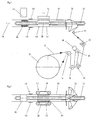
- schematische Darstellung eines Ausführungsbeispiel der erfindungsgemäßen Vorrichtung zum Herstellen von Folienschlauch in der Seitenansicht und
- Fig. 2
- das Ausführungsbeispiel gemäß Fig. 1 in der Draufsicht.
- Fig. 1
- schematic representation of an embodiment of the inventive device for producing film tube in the side view and
- Fig. 2
- the embodiment of FIG. 1 in plan view.
Die Vorrichtung gemäß Fig. 1 weist eine Vorratsrolle 10 eines zur Verarbeitung anstehenden Folienbandes 12 auf. Das Folienband 12 wird über mehrere Umlenkrollen 14, 16, 18, 20, 22 und 24 an eine Formschulter 26 herangeführt. Im Bereich einer der Umlenkrollen 18 liegt eine Zählrad 28 auf der der Umlenkrolle 18 gegenüberliegenden Oberfläche an dem Folienband 12 an. Die Umlenkrolle 18 bildet also die Andruckrolle für das Zählrad 28.The device according to FIG. 1 has a
Das Folienband wird in der Formschulter 26 zu einem Folienschlauch 30 um ein Füllrohr 32 herum umgeformt. Dabei umgibt der Folienschlauch 30 das Füllrohr 32 im Wesentlichen koaxial. Der Folienschlauch weist nach der Umformung zwei, gemäß der Ansicht in Fig. 1 oben liegende, jedoch nicht dargestellte, benachbarte Längskanten auf, die in einer der Formschulter 26 in Füllausstoßrichtung (vgl. Pfeil 36) stromabwärts angeordneten Siegelstation 34 versiegelt bzw. verschweißt werden. In gleicher Höhe mit der Siegelstation 34 befindet sich beiderseits des Füllrohres jeweils ein auf der Außenseite des Folienschlauchs 30 anliegender Antriebsriemen 38, 39 eines Vorschubantriebs 40, der Folienband nachund unter Siegelstation hindurchzieht und gleichzeitig den fertigen Folienschlauch in Füllausstoßrichtung 36 schiebt. Im Bereich der Siegelstation 34 und des Vorschubantriebs 40 ist koaxial auf dem Füllrohr 32 ein Ring 42 angeordnet, dessen Außendurchmesser in etwa dem Durchmesser des fertigen Folienschlauchs 30 entspricht. Unter Andruck gegen diesen Ring 42 wirken sowohl die Antriebsriemen 38, 39 als auch Siegelstation 34 (genauer ein Siegelbalken, Siegelband oder Heißluftstrom der Siegelstation).The film strip is formed in the forming
Stromabwärts der Siegelstation 34 befindet sich koaxial auf dem Füllrohr 32 ein Rückhaltering 44. Da der Vorschubantrieb 40 in Vorschubrichtung vor dem Rückhaltering 44 wirkt und der Folienschlauch keine ausreichende Eigenstabilität aufweist, bildet sich ein ziehharmonikaartig gefalteter Folienschlauchvorrat 46 auf einer Pufferstrecke 45 zwischen dem Rückhaltering 44 und dem Vorschubantrieb 40. Weil es bei der erfindungsgemäßen Vorrichtung jedoch nicht auf die Stärke der Faltung ankommt, kann diese beispielsweise unter Berücksichtigung der Empfindlichkeit des Folienmaterials durch eine entsprechende Wahl der Länge der Pufferstrecke 45 bei gleicher Vorratskapazität oder bei vorgegebener Länge der Pufferstrecke 45 durch eine Reduzierung der Vorratsmenge verringert werden.Downstream of the sealing
Der Folienschlauch 30 wird dann beim Abfüllvorgang in Füllausstoßrichtung 36 über den Rückhaltering von dem Puffervorrat abgezogen. In Höhe des Rückhalterings 44 oder in Füllausstoßrichtung 36 dahinter, d.h. an der Stelle, an der die Folie durch das Abziehen von dem Vorrat 46 wieder gestreckt ist, befindet sich ein zweiter Sensor 48 der Messeinrichtung. Dieser Sensor 48 kann ebenfalls wie der erste Sensor 28 als ein an der Außenseite des Folienschlauches beispielsweise im Bereich des Rückhalterings 44 als Gegendruckstück anliegendes Zählrad ausgestaltet sein.The
Nachfolgend wird das Herstellungsverfahren von mit flüssigem, viskosem oder granularem Füllgut befüllbarem Folienschlauch aus einem Folienband mittels der erfindungsgemäßen Vorrichtung beschrieben. In einem ersten Schritt wird das Folienband 12 von einem Folienbandvorrat 10 der Umformeinrichtung 26 zugeführt. Das Folienband 12 wird in der Umformeinrichtung 26 zu einem Folienschlauch 30 um ein Füllrohr 32 herum umgeformt und danach in einer Schweißoder Siegeleinrichtung 34 der nach der Umformung überlappenden oder nebeneinanderliegenden Längskanten mit oder ohne Verwendung eines zusätzlichen Siegelstreifens zu dem geschlossenen Folienschlauch 30 verschweißt oder versiegelt. Des versiegelte Folienschlauch 30 wird danach mittels eines Vorschubantriebs 40 von der Siegeleinrichtung 34 an einen Folienschlauchvorrat 46 auf dem Füllrohr 32 abgegeben, von dem er durch den Füllvorgang bedingt bei Bedarf wieder abgezogen wird, wobei die Länge des an den Folienschlauchvorrat 46 abgegebenen und die Länge des von dem Folienschlauchvorrat 46 abgezogenen Folienschlauchs 30 erfasst und einer (elektronischen) Regelung zugeführt wird, die den Siegelvorgang bzw. die Siegelgeschwindigkeit so regelt, dass eine vorbestimmte, möglichst gleichbleibende Vorratsmenge an Folienschlauch bereitgehalten wird.The production process of film tube filled with liquid, viscous or granular filling material from a foil strip by means of the device according to the invention will be described below. In a first step, the
Bei Betriebsbeginn oder Folienbandwechsel muss zunächst eine bestimmte Menge Folienschlauch vorgesiegelt werden, damit ein einwandfreier Anlauf der Gesamtanlage (Siegelvorrichtung und Clipmaschine) gewährleistet ist. Diese bestimmte Menge kann dann durch die erfindungsgemäße Messung und Regelung der Siegelgeschwindigkeit beibehalten werden.At the start of operation or film tape change, a certain amount of film tube must first be pre-sealed, so that a perfect start of the entire system (sealing device and clip machine) is guaranteed. This certain amount can then be maintained by the inventive measurement and control of the sealing speed.
Claims (5)
dadurch gekennzeichnet, dass in Füllausstoßrichtung (36) nach der Umformeinrichtung (26) eine erste Leseeinrichtung (48) zum Lesen von auf dem Folienschlauch (30) befindlichen Druckmarkierungen vorgesehen ist.Apparatus for producing a film tube (12) which can be filled with liquid, viscous or granular filling material, comprising a filling tube (32) which can be connected to a filling machine for the filling material, a forming device (26) surrounding the filling tube (32) for shaping the foil strip ( 12) to form a film tube (30), a sealing device (34) arranged in the filling ejection direction (36) behind the forming device (26) for sealing longitudinal edges of the film strip (12) adjacent to the forming in order to form a film tube (30), and with a feed drive (40) for the film tube (30),
characterized in that in Füllausstoßrichtung (36) after the forming device (26) is provided a first reading means (48) for reading on the film tube (30) located pressure marks.
dadurch gekennzeichnet, dass in Füllausstoßrichtung (36) vor der Umformeinrichtung (26) eine zweite Leseeinrichtung (28) zum Lesen von auf dem Folienband (12) vorgesehenen Druckmarkierungen angeordnet ist.Device according to claim 1,
characterized in that a second reading device (28) for reading printing marks provided on the film strip (12) is arranged in the filling ejection direction (36) in front of the forming device (26).
dadurch gekennzeichnet, dass in Füllausstoßrichtung (36) vor der Umformeinrichtung (26) eine Schreibeinrichtung zum Aufbringen von durch zumindest die erste Leseeinrichtung (28) lesbaren Druckmarkierungen vorgesehen ist.Device according to 1 or 2,
characterized in that in the Füllausstoßrichtung (36) in front of the forming device (26) is provided a writing device for applying readable by at least the first reading means (28) pressure marks.
dadurch gekennzeichnet, dass das Folienband (12) mit durch eine Leseeinrichtung (28, 48) lesbaren Druckmarkierungen versehen ist.Foil strip for producing film tube that can be filled with liquid, viscous or granular filling material,
characterized in that the film strip (12) is provided with readable by a reading device (28, 48) pressure marks.
Applications Claiming Priority (2)
| Application Number | Priority Date | Filing Date | Title |
|---|---|---|---|
| DE102004032183A DE102004032183B4 (en) | 2004-07-02 | 2004-07-02 | Device for producing film tube from a foil strip |
| EP05013358A EP1611792B1 (en) | 2004-07-02 | 2005-06-21 | Apparatus for manufacturing a tubular film from a film tape |
Related Parent Applications (2)
| Application Number | Title | Priority Date | Filing Date |
|---|---|---|---|
| EP05013358A Division EP1611792B1 (en) | 2004-07-02 | 2005-06-21 | Apparatus for manufacturing a tubular film from a film tape |
| EP05013358.6 Division | 2005-06-21 |
Publications (3)
| Publication Number | Publication Date |
|---|---|
| EP1797764A2 true EP1797764A2 (en) | 2007-06-20 |
| EP1797764A3 EP1797764A3 (en) | 2007-07-04 |
| EP1797764B1 EP1797764B1 (en) | 2012-12-05 |
Family
ID=34982368
Family Applications (2)
| Application Number | Title | Priority Date | Filing Date |
|---|---|---|---|
| EP05013358A Active EP1611792B1 (en) | 2004-07-02 | 2005-06-21 | Apparatus for manufacturing a tubular film from a film tape |
| EP07007000A Active EP1797764B1 (en) | 2004-07-02 | 2005-06-21 | Apparatus for manufacturing a tubular film from a film tape |
Family Applications Before (1)
| Application Number | Title | Priority Date | Filing Date |
|---|---|---|---|
| EP05013358A Active EP1611792B1 (en) | 2004-07-02 | 2005-06-21 | Apparatus for manufacturing a tubular film from a film tape |
Country Status (7)
| Country | Link |
|---|---|
| US (1) | US7310926B2 (en) |
| EP (2) | EP1611792B1 (en) |
| JP (1) | JP4694901B2 (en) |
| CN (1) | CN100532204C (en) |
| BR (1) | BRPI0502538A (en) |
| DE (2) | DE102004032183B4 (en) |
| ES (2) | ES2285607T3 (en) |
Families Citing this family (23)
| Publication number | Priority date | Publication date | Assignee | Title |
|---|---|---|---|---|
| DE202004007711U1 (en) * | 2004-05-13 | 2004-08-12 | Tipper Tie Technopack Gmbh | Sausage packaging device for filling pasty contents in tubular casing material |
| DE102004032183B4 (en) * | 2004-07-02 | 2007-04-12 | Poly-Clip System Gmbh & Co Kg | Device for producing film tube from a foil strip |
| JP4563166B2 (en) * | 2004-12-17 | 2010-10-13 | 日本テトラパック株式会社 | Filling machine and filling monitoring method |
| US7934361B2 (en) * | 2005-10-19 | 2011-05-03 | Orihiro Engineering Co., Ltd. | Packaging apparatus |
| US7544118B2 (en) * | 2006-10-25 | 2009-06-09 | Poly-Clip System Corp. | Hybrid filling system |
| DE102006052023A1 (en) * | 2006-11-03 | 2008-05-08 | Poly-Clip System Gmbh & Co. Kg | Filling device and method for filling viscous medium |
| DE202007004908U1 (en) * | 2007-04-03 | 2007-06-14 | Poly-Clip System Gmbh & Co. Kg | Film tube producing device, has sealing device arranged behind transformation device in filling expulsion direction for sealing longitudinal edges of strip, where writing device is in condition to attach printed label on strip or tube |
| DE102011075431A1 (en) * | 2011-05-06 | 2012-11-08 | Robert Bosch Gmbh | Method for optimizing the conveyance of a packaging material web in the region of a tube forming device of a tubular bag machine |
| DE102011076922A1 (en) * | 2011-06-03 | 2012-12-06 | Robert Bosch Gmbh | Method for detecting the transverse position of a packaging material, in particular a film packaging |
| CN102424153B (en) * | 2011-08-30 | 2013-06-12 | 长沙琦清机械设备有限公司 | Film combining machine |
| US9999233B1 (en) | 2012-04-13 | 2018-06-19 | Viskase Companies, Inc. | Low moisture barrier film |
| US20150119217A1 (en) * | 2013-10-31 | 2015-04-30 | Tipper Tie, Inc. | Systems with film speed control and related devices, methods and computer program products |
| US20150119218A1 (en) * | 2013-10-31 | 2015-04-30 | Tipper Tie, Inc. | Systems with pre-heaters for producing seamed encased products and related devices, methods and computer program products |
| US10821703B1 (en) | 2014-06-27 | 2020-11-03 | Vikase Companies, Inc. | Additive transferring film |
| US9669952B2 (en) | 2014-10-31 | 2017-06-06 | Tipper Tie, Inc. | Systems with wheel saddles that can cooperate with wheels of encoders and related devices and methods |
| CN105173161A (en) * | 2015-07-29 | 2015-12-23 | 深圳市金奥博科技有限公司 | Intelligent plastic film molding heat sealing machine |
| EP3141488B1 (en) * | 2015-09-09 | 2020-04-22 | Tetra Laval Holdings & Finance S.A. | Packaging machine for producing packages from a sheet of packaging material |
| WO2017055556A1 (en) | 2015-09-30 | 2017-04-06 | Poly-Clip System Gmbh & Co. Kg | Sealable casing material |
| ES2706273T3 (en) * | 2015-12-22 | 2019-03-28 | Poly Clip System Gmbh & Co Kg | Wrap brake assembly |
| US11110666B2 (en) | 2018-02-12 | 2021-09-07 | Tipper Tie, Inc. | Systems with external heat-seal assembly height adjustment control and related seal assemblies |
| CN110435953A (en) * | 2019-09-03 | 2019-11-12 | 汕头市乐甜糖果食品有限公司 | A kind of filling packing integral machine of jelly |
| DE102021121988A1 (en) | 2021-08-25 | 2023-03-02 | Roland Wolf | Device for producing a tubular film from a strip of film using the form shoulder welding process |
| CN114084448B (en) * | 2021-11-23 | 2023-03-24 | 安徽荣冠管业科技有限公司 | Drying and film covering device for production of drain pipe |
Citations (1)
| Publication number | Priority date | Publication date | Assignee | Title |
|---|---|---|---|---|
| EP0908103A1 (en) | 1997-10-06 | 1999-04-14 | Poly-clip System GmbH | Method and device for making and stuffing of a tubular casing |
Family Cites Families (33)
| Publication number | Priority date | Publication date | Assignee | Title |
|---|---|---|---|---|
| US4479283A (en) * | 1982-01-18 | 1984-10-30 | H-Worth, Inc. | Method of and apparatus for stuffing foodstuff into a casing |
| DE3236553A1 (en) * | 1982-10-02 | 1984-04-12 | Herbert Dipl.-Ing. 6240 Königstein Niedecker | METHOD FOR PRODUCING TUBULAR PACKAGING SLEEVES FROM AN ENDLESS FILM COATING |
| DE3244085C1 (en) * | 1982-11-29 | 1984-03-22 | Günter 6080 Groß-Gerau Kollross | Method and device for opening, axially gathering and separating thin-walled tubular casing material and for subsequently transferring the beads thus formed to a further processing point |
| EP0129988B1 (en) * | 1983-05-31 | 1987-09-30 | Tokyo Automatic Machinery Works Limited | Apparatus for producing and filling bags |
| DE3435948A1 (en) * | 1984-09-29 | 1986-04-03 | Herbert Dipl.-Ing. 6240 Königstein Niedecker | METHOD FOR PRODUCING PACKING HOSES FROM PLASTIC FILMS |
| US4570301A (en) * | 1984-10-29 | 1986-02-18 | Union Carbide Corporation | Stuffing horn clean out |
| JPS6245633A (en) * | 1985-08-26 | 1987-02-27 | Nikka Jushi Kk | Surface treatment of film |
| US4734956A (en) * | 1986-01-08 | 1988-04-05 | Viskase Corporation | Food casing article |
| DE3608983A1 (en) * | 1986-03-18 | 1987-10-01 | Niedecker Herbert | Method for sealing a filled packaging casing |
| US4766645A (en) * | 1987-04-16 | 1988-08-30 | Viskase Corporation | Size control system for stuffing machine |
| IT1240311B (en) * | 1989-12-29 | 1993-12-07 | Cavanna Spa | PROCEDURE TO CHECK THE ADVANCE OF THE WINDING FILM IN WRAPPING MACHINES AND RELATED WRAPPING MACHINE |
| JPH04239426A (en) * | 1990-12-28 | 1992-08-27 | Nippon Seiki Co Ltd | Film feeding device for packaging machine and the like |
| IT1251148B (en) * | 1991-08-05 | 1995-05-04 | Sitma Spa | SEALING EQUIPMENT WITH PAPER GLUE MATERIAL OR SIMILAR PACKAGING MACHINE IN A PACKAGING MACHINE FOR PUBLISHING GRAPHIC PRODUCTS |
| DE9400771U1 (en) * | 1994-01-18 | 1994-03-03 | Poly Clip System Gmbh | Device for closing filled packaging casings |
| DE4412697C1 (en) * | 1994-04-13 | 1995-07-06 | Poly Clip System Gmbh | Controlled filling of tubular packaging sleeves with paste-like material |
| US5485712A (en) * | 1995-01-27 | 1996-01-23 | Hayssen Manufacturing Company | Method of handling film on a vertical form, fill and seal machine |
| DE19517127A1 (en) * | 1995-05-10 | 1996-11-14 | Frey Heinrich Maschinenbau | Paste portioning appts. esp. for sausage skin filling |
| DE19519394C2 (en) * | 1995-05-26 | 1997-03-13 | Poly Clip System Gmbh & Co Kg | Process for making sausages |
| US5600308A (en) * | 1995-06-23 | 1997-02-04 | Devro-Teepak, Inc. | Method for detecting a position on a product |
| IT1299965B1 (en) * | 1998-04-08 | 2000-04-04 | Gd Spa | METHOD AND UNIT FOR THE FEEDING OF A RIBBON OF SHEET MATERIAL. |
| JP3016388B2 (en) * | 1998-05-28 | 2000-03-06 | 日本精機株式会社 | Filling and packaging machine |
| JP2000190907A (en) * | 1998-08-31 | 2000-07-11 | Nippon Seiki Co Ltd | Filling and packaging machine |
| JP2000171235A (en) * | 1998-12-09 | 2000-06-23 | Omori Mach Co Ltd | Instrument and method for measuring rolled film diameter |
| US6131373A (en) * | 1999-02-18 | 2000-10-17 | Hayssen, Inc. | Vertical form, fill and seal machine having constant film pull length |
| EP1095570A1 (en) * | 1999-10-29 | 2001-05-02 | Tipper Tie Alpina AG | Double clipper device |
| ES2209799T3 (en) * | 2000-07-03 | 2004-07-01 | TETRA LAVAL HOLDINGS & FINANCE S.A. | PACKING MACHINE TO PRODUCE CONTINUOUSLY PACKS OBTAINED FROM A VERTIBLE FOOD PRODUCT AND WHICH IS PROVIDED WITH PROGRAMMABLE PHOTOELECTRIC CELLS. |
| NL1016524C2 (en) * | 2000-11-01 | 2002-05-07 | Aquarius Bv | Forming, filling and closing machine. |
| JP2003199486A (en) * | 2002-01-07 | 2003-07-15 | Terada Trading Kk | Device for producing sausage and method for producing the same |
| US6719621B2 (en) * | 2002-05-31 | 2004-04-13 | Townsend Engineering Company | Method and means for stuffing natural casings with sausage emulsion |
| US6669545B1 (en) * | 2002-08-23 | 2003-12-30 | Townsend Engineering Company | Method and means for stuffing natural casings with a food emulsion |
| DE102004024419B4 (en) * | 2004-05-14 | 2008-10-09 | Kalle Gmbh | Food product, in particular a sausage product, arrangement and method for its production and casing of the product |
| DE102004032183B4 (en) * | 2004-07-02 | 2007-04-12 | Poly-Clip System Gmbh & Co Kg | Device for producing film tube from a foil strip |
| JP2006030000A (en) * | 2004-07-16 | 2006-02-02 | Fuji Photo Film Co Ltd | Machine for measuring length |
-
2004
- 2004-07-02 DE DE102004032183A patent/DE102004032183B4/en not_active Expired - Fee Related
-
2005
- 2005-06-21 EP EP05013358A patent/EP1611792B1/en active Active
- 2005-06-21 EP EP07007000A patent/EP1797764B1/en active Active
- 2005-06-21 DE DE502005000543T patent/DE502005000543D1/en active Active
- 2005-06-21 ES ES05013358T patent/ES2285607T3/en active Active
- 2005-06-21 ES ES07007000T patent/ES2398288T3/en active Active
- 2005-06-28 US US11/160,540 patent/US7310926B2/en active Active
- 2005-06-30 BR BRPI0502538-9A patent/BRPI0502538A/en active Search and Examination
- 2005-07-01 JP JP2005193744A patent/JP4694901B2/en not_active Expired - Fee Related
- 2005-07-04 CN CNB2005100913735A patent/CN100532204C/en active Active
Patent Citations (1)
| Publication number | Priority date | Publication date | Assignee | Title |
|---|---|---|---|---|
| EP0908103A1 (en) | 1997-10-06 | 1999-04-14 | Poly-clip System GmbH | Method and device for making and stuffing of a tubular casing |
Also Published As
| Publication number | Publication date |
|---|---|
| JP2006016079A (en) | 2006-01-19 |
| CN1736800A (en) | 2006-02-22 |
| US20060000188A1 (en) | 2006-01-05 |
| ES2398288T3 (en) | 2013-03-15 |
| DE502005000543D1 (en) | 2007-05-16 |
| US7310926B2 (en) | 2007-12-25 |
| EP1611792A3 (en) | 2006-04-12 |
| JP4694901B2 (en) | 2011-06-08 |
| EP1797764A3 (en) | 2007-07-04 |
| ES2285607T3 (en) | 2007-11-16 |
| DE102004032183A1 (en) | 2006-01-26 |
| EP1611792A2 (en) | 2006-01-04 |
| BRPI0502538A (en) | 2006-02-14 |
| EP1611792B1 (en) | 2007-04-04 |
| DE102004032183B4 (en) | 2007-04-12 |
| EP1797764B1 (en) | 2012-12-05 |
| CN100532204C (en) | 2009-08-26 |
Similar Documents
| Publication | Publication Date | Title |
|---|---|---|
| EP1611792B1 (en) | Apparatus for manufacturing a tubular film from a film tape | |
| EP3642144B1 (en) | Apparatus for supplying a coil-like padding product for packaging purposes | |
| EP0913352B1 (en) | Buckling folder and method for registration control of a buckling folder | |
| DE102005053319A1 (en) | Device for manufacturing of filling material and padding section to pack articles, has retaining device whereby retaining device is designed to hold roll of wound material web | |
| EP1977649B1 (en) | Invisible printed mark | |
| EP1714926B1 (en) | Method for controlling and/or monitoring a web processing machine | |
| DE102014216191A1 (en) | Method and device for applying a shrink-film sleeve | |
| EP1713641B1 (en) | Method and device for threading a web | |
| EP1918206A1 (en) | Filling device and method for filling viscose bulk material | |
| DE4113772A1 (en) | METHOD FOR REPLACING STRIP MATERIAL ON A PRODUCTION MACHINE | |
| EP1781462B1 (en) | Installation for producing folded labels | |
| DE10204313A1 (en) | Method and device for cutting label sleeves from a flat label tube tape | |
| EP2285719B1 (en) | Device and method for winding strip-shaped material and strip processing machine | |
| DE3152881A1 (en) | Method for coding articles using a coded label | |
| DE19516868C2 (en) | Tubular bag machine | |
| DE102020102744A1 (en) | Manufacturing machine for the manufacture of rod-shaped products from an endless strand of a strip glued to form a tube | |
| DE102015200309A1 (en) | Device and method for separating printing material | |
| EP0569336B1 (en) | Apparatus for making flat packaging bags from a flexible film | |
| DE10307678A1 (en) | Hose and device and method for producing the same | |
| DE102008022702B4 (en) | Method and apparatus for unwinding and storing sheet material | |
| DE10058437B4 (en) | Devices for connecting two webs of material | |
| EP0803460A2 (en) | Device for laying foil-web in Z-shaped folds | |
| DE102019110339A1 (en) | Printing and labeling machine and method for individualized printing of labels | |
| DE102011003666A1 (en) | Tubular bag machine for manufacturing bag used for packing food product, has motion sensor and film web drive units that are connected with control element which controls state of motion of film web portion | |
| WO2005060771A2 (en) | Oscillator for a printing group of the tobacco-processing industry |
Legal Events
| Date | Code | Title | Description |
|---|---|---|---|
| PUAI | Public reference made under article 153(3) epc to a published international application that has entered the european phase |
Free format text: ORIGINAL CODE: 0009012 |
|
| PUAL | Search report despatched |
Free format text: ORIGINAL CODE: 0009013 |
|
| AC | Divisional application: reference to earlier application |
Ref document number: 1611792 Country of ref document: EP Kind code of ref document: P |
|
| AK | Designated contracting states |
Kind code of ref document: A2 Designated state(s): CH DE ES IT LI |
|
| AK | Designated contracting states |
Kind code of ref document: A3 Designated state(s): CH DE ES IT LI |
|
| 17P | Request for examination filed |
Effective date: 20080104 |
|
| RIN1 | Information on inventor provided before grant (corrected) |
Inventor name: HANTEN, JUERGEN Inventor name: FREY, EDMUND Inventor name: NIKOLEY, WOLFGANG |
|
| AKX | Designation fees paid |
Designated state(s): CH DE ES IT LI |
|
| 17Q | First examination report despatched |
Effective date: 20080215 |
|
| REG | Reference to a national code |
Ref country code: DE Ref legal event code: R079 Ref document number: 502005013319 Country of ref document: DE Free format text: PREVIOUS MAIN CLASS: A22C0013000000 Ipc: A22C0011020000 |
|
| RIC1 | Information provided on ipc code assigned before grant |
Ipc: A22C 13/00 20060101ALI20120327BHEP Ipc: A22C 11/02 20060101AFI20120327BHEP |
|
| GRAP | Despatch of communication of intention to grant a patent |
Free format text: ORIGINAL CODE: EPIDOSNIGR1 |
|
| GRAS | Grant fee paid |
Free format text: ORIGINAL CODE: EPIDOSNIGR3 |
|
| RAP1 | Party data changed (applicant data changed or rights of an application transferred) |
Owner name: POLY-CLIP SYSTEM GMBH & CO. KG |
|
| GRAA | (expected) grant |
Free format text: ORIGINAL CODE: 0009210 |
|
| AC | Divisional application: reference to earlier application |
Ref document number: 1611792 Country of ref document: EP Kind code of ref document: P |
|
| AK | Designated contracting states |
Kind code of ref document: B1 Designated state(s): CH DE ES IT LI |
|
| REG | Reference to a national code |
Ref country code: CH Ref legal event code: EP |
|
| REG | Reference to a national code |
Ref country code: DE Ref legal event code: R096 Ref document number: 502005013319 Country of ref document: DE Effective date: 20130131 |
|
| REG | Reference to a national code |
Ref country code: ES Ref legal event code: FG2A Ref document number: 2398288 Country of ref document: ES Kind code of ref document: T3 Effective date: 20130315 |
|
| REG | Reference to a national code |
Ref country code: CH Ref legal event code: NV Representative=s name: WAGNER PATENT AG, CH |
|
| PLBE | No opposition filed within time limit |
Free format text: ORIGINAL CODE: 0009261 |
|
| STAA | Information on the status of an ep patent application or granted ep patent |
Free format text: STATUS: NO OPPOSITION FILED WITHIN TIME LIMIT |
|
| 26N | No opposition filed |
Effective date: 20130906 |
|
| REG | Reference to a national code |
Ref country code: DE Ref legal event code: R097 Ref document number: 502005013319 Country of ref document: DE Effective date: 20130906 |
|
| REG | Reference to a national code |
Ref country code: CH Ref legal event code: PCAR Free format text: NEW ADDRESS: BAECHERSTRASSE 9, 8832 WOLLERAU (CH) |
|
| PGFP | Annual fee paid to national office [announced via postgrant information from national office to epo] |
Ref country code: ES Payment date: 20160622 Year of fee payment: 12 |
|
| REG | Reference to a national code |
Ref country code: ES Ref legal event code: FD2A Effective date: 20181113 |
|
| PG25 | Lapsed in a contracting state [announced via postgrant information from national office to epo] |
Ref country code: ES Free format text: LAPSE BECAUSE OF NON-PAYMENT OF DUE FEES Effective date: 20170622 |
|
| PGFP | Annual fee paid to national office [announced via postgrant information from national office to epo] |
Ref country code: IT Payment date: 20220630 Year of fee payment: 18 |
|
| PGFP | Annual fee paid to national office [announced via postgrant information from national office to epo] |
Ref country code: CH Payment date: 20220629 Year of fee payment: 18 |
|
| P01 | Opt-out of the competence of the unified patent court (upc) registered |
Effective date: 20230519 |
|
| PGFP | Annual fee paid to national office [announced via postgrant information from national office to epo] |
Ref country code: DE Payment date: 20230707 Year of fee payment: 19 |
|
| REG | Reference to a national code |
Ref country code: CH Ref legal event code: PL |
|
| PG25 | Lapsed in a contracting state [announced via postgrant information from national office to epo] |
Ref country code: CH Free format text: LAPSE BECAUSE OF NON-PAYMENT OF DUE FEES Effective date: 20230630 |