EP1797751B1 - Verteilmaschine - Google Patents
Verteilmaschine Download PDFInfo
- Publication number
- EP1797751B1 EP1797751B1 EP06291900A EP06291900A EP1797751B1 EP 1797751 B1 EP1797751 B1 EP 1797751B1 EP 06291900 A EP06291900 A EP 06291900A EP 06291900 A EP06291900 A EP 06291900A EP 1797751 B1 EP1797751 B1 EP 1797751B1
- Authority
- EP
- European Patent Office
- Prior art keywords
- product
- spread
- spreader
- opening
- door
- Prior art date
- Legal status (The legal status is an assumption and is not a legal conclusion. Google has not performed a legal analysis and makes no representation as to the accuracy of the status listed.)
- Not-in-force
Links
- 238000000034 method Methods 0.000 claims abstract description 16
- 238000006073 displacement reaction Methods 0.000 claims abstract 3
- 238000005259 measurement Methods 0.000 claims description 12
- 238000005303 weighing Methods 0.000 claims description 8
- 238000007789 sealing Methods 0.000 claims 10
- 230000007480 spreading Effects 0.000 description 10
- 238000003892 spreading Methods 0.000 description 10
- 230000001276 controlling effect Effects 0.000 description 4
- 210000003608 fece Anatomy 0.000 description 4
- 239000010871 livestock manure Substances 0.000 description 4
- 230000004044 response Effects 0.000 description 4
- 230000008859 change Effects 0.000 description 3
- 239000002361 compost Substances 0.000 description 3
- 238000001914 filtration Methods 0.000 description 3
- 238000001595 flow curve Methods 0.000 description 3
- 230000003247 decreasing effect Effects 0.000 description 2
- 230000000694 effects Effects 0.000 description 2
- 230000001105 regulatory effect Effects 0.000 description 2
- 238000003860 storage Methods 0.000 description 2
- 230000001133 acceleration Effects 0.000 description 1
- 238000009825 accumulation Methods 0.000 description 1
- 230000002596 correlated effect Effects 0.000 description 1
- 238000005314 correlation function Methods 0.000 description 1
- 230000000875 corresponding effect Effects 0.000 description 1
- 238000010586 diagram Methods 0.000 description 1
- 238000009826 distribution Methods 0.000 description 1
- 235000021183 entrée Nutrition 0.000 description 1
- 210000000887 face Anatomy 0.000 description 1
- 210000001061 forehead Anatomy 0.000 description 1
- 230000001939 inductive effect Effects 0.000 description 1
- 230000001788 irregular Effects 0.000 description 1
- 230000007246 mechanism Effects 0.000 description 1
- 239000011368 organic material Substances 0.000 description 1
- 230000008092 positive effect Effects 0.000 description 1
- 238000011144 upstream manufacturing Methods 0.000 description 1
Images


Classifications
-
- A—HUMAN NECESSITIES
- A01—AGRICULTURE; FORESTRY; ANIMAL HUSBANDRY; HUNTING; TRAPPING; FISHING
- A01C—PLANTING; SOWING; FERTILISING
- A01C3/00—Treating manure; Manuring
- A01C3/06—Manure distributors, e.g. dung distributors
-
- A—HUMAN NECESSITIES
- A01—AGRICULTURE; FORESTRY; ANIMAL HUSBANDRY; HUNTING; TRAPPING; FISHING
- A01C—PLANTING; SOWING; FERTILISING
- A01C15/00—Fertiliser distributors
- A01C15/12—Fertiliser distributors with movable parts of the receptacle
- A01C15/124—Fertiliser distributors with movable parts of the receptacle with adjustable shutters or slits
Definitions
- the subject of the present invention is a spreader and a method for controlling the mass flow rate of a product to be spread out ejected from a spreader.
- Spreading of manure, compost or cocompost type organic material is generally carried out by means of spreaders.
- the spreaders are more and more equipped with electronic control means.
- the control means may in particular control a hydraulic device for driving a moving belt disposed at the bottom of the spreader, so as to adjust the speed of the moving belt according to the speed of the spreader, the objective being obtain the desired amount of product at each point of a plot.
- the figure 1 shows a curve 1 representing the theoretical evolution of a mass flow rate Dmt of a spreading product ejected from a spreader as a function of time t.
- Curve 1 corresponds to what an operator wishes to obtain, that is to say a spread substantially constant for a duration Tv corresponding to a theoretical emptying time.
- a curve 2 represents the actual evolution of the mass flow Dmr during the spreading of a product such as cocompost by a spreader of the prior art.
- Curve 2 has large variations with respect to curve 1, in particular at the beginning and end of emptying. The actual start of the emptying is prior to the theoretical time and the actual end of the emptying is later than the theoretical moment, which has the effect of a real mass flow Dmr lower than desired.
- variations in the instantaneous value of the mass flow rate Dmr are due in particular to product landslides to dispersing members of the spreader.
- a first method consists in using a torque indicator consumed by the scattering members, this torque being strongly correlated with the mass flow rate.
- this method has the disadvantage that the correlation function varies for each type of product.
- the measurements being made when the product is spread, mass flow variation information is only available after spreading, which limits the effectiveness of the control.
- a second method is to use a weighing shutter to weigh a "slice" of product just before it passes through the scatterers.
- This method has the disadvantage of a lack of reliability, because of the vault effect of the product on the walls of the spreader, which causes a partial weighing of the product moving in the body of the spreader.
- a third method is to use a so-called global weighing, ie to extract mass flow information from that of the total weight of the product present in the spreader box at any time.
- This method makes it possible to obtain reliable information on the mass of product spread at every moment.
- this method has the disadvantage of having a delay during regulation because of the need for a large filtering, especially because of dynamic accelerations and product density variations.
- a spreader comprising the features of the preamble of claim 1 and using the method according to the preamble of claim 12 is known from EP-A-0858729 .
- the present invention aims to provide a spreader that avoids at least some of the aforementioned drawbacks and allows an effective control of the mass flow, and a method for controlling the mass flow rate of a spread product ejected from a spreader.
- the subject of the invention is a spreader comprising the features of claim 1.
- said characteristic parameter is relative to the height of product in the vicinity of said opening zone.
- said means for determining a characteristic parameter comprise means for measuring the force of a force exerted by said product on said closure means.
- said force measuring means comprise a set of sensors comprising at least one sensor of analog type.
- said closure means comprise a door supported and held in position by means for actuating the door connected to said box, said force measuring means being able to measure a force exerted. on said actuating means.
- the closure means comprise a door slidably mounted in slides secured to said box, the force measuring means being able to measure a force exerted by said door on said slides.
- the closure means comprise a door, the lower part of the door comprising an articulated device, said door comprising a sensor support adapted to block a rotation of said articulated device, said measuring means force being able to measure a force exerted by said product to spread on said articulated device.
- said force measuring means comprise a set of sensors comprising at least one Boolean type sensor.
- the closure means comprise a door, the lower part of the door comprising an articulated device, said door comprising a sensor support adapted to block a rotation of said articulated device, a mechanical device capable of being compressed being disposed between said articulated device and said sensor support, said force measuring means being able to transmit a signal whose value indicates whether said mechanical device and compressed or not.
- the spreader comprises storage means able to memorize the distance between said shutter means and dispersing members of the spreader, so that the adjustment of the speed of the moving belt takes into account the difference between the instant of determination of the characteristic parameter of a portion of the product and the instant of the ejection of the product portion of the spreader.
- the spreader comprises weighing means capable of weighing the spreading product contained in the box, and input means for entering a volume of product to spread in the box, the spreader comprising a control unit. capable of determining the density of the product to be spread according to the mass of the product to be spread and the volume of the product to be spread.
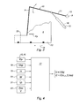
- the box 3 contains a product to spread 4, for example manure, compost or cocompost.
- the body 3 is closed on its lower face 5, its front face 6, and its two lateral faces (not shown), and is open on its rear face which constitutes an opening 7 for the ejection of the product 4.
- scattering 8 are arranged at the opening.
- the opening 7 is able to be totally or partially closed by a door 9, arranged upstream of the scattering members 8.
- the door 9 is held in position by means for actuating the door 10, which comprise a portion 11 mobile in rotation about an axis A, and a cylinder 12.
- Force sensors 15 and 16 arranged at the axis A and in the jack 12, for example, allow measurements of the force Fp exerted by the product 4 on the door 9. It will be noted that this arrangement of the sensors of 15, 16 makes it possible to perform a total measurement of the force that applies to the door 9.
- the sensors 15, 16 may be, for example, conventional analog response type stress sensors, stress measurement bars. , or pressure sensors.
- the computer is connected to input means 22, which include for example a keypad, to allow an operator to enter spreading parameters, as will be described in detail below.
- the computer 17 calculates, from the mass M of the product, measured by the weighing means 20, and the volume V of the product, entered by the user, the density ⁇ of the product.
- the force sensors 15, 16 transmit to the computer 17 force measurements Fp exerted by the product 4 on the door 9.
- the computer 17 determines a height H adapted to the door and controls a movement of the cylinder 12.
- the adapted height H is for example chosen such that the door 9 arase the product 4 by a few centimeters.
- the computer 17 calculates the opening area S of the box 3, that is to say the surface through which the product 4 can exit the spreader.
- the profile of the body, including its width, is previously stored in the computer 17.
- the surface S is thus reliably and measurably known by a simple door position sensor, inexpensive and whose signal does not require filtering.
- the computer 17 derives the speed Vt to be applied to the belt, as a function of the desired mass flow Dmt, the opening surface S and the density ⁇ .
- the actual mass flow rate Dmr which depends on the speed Vep of the spreader, the density ⁇ of the product 4, the speed Vt of the belt and the surface S can be regulated to remain close to the desired mass flow Dmt .
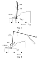
- the door 109 and a so-called guillotine door which is slidably mounted between two slideways 126, only one of which is visible on the figure 4 , arranged in the profile of the box 103.
- the force sensors 115, 116 are arranged in a bearing pad 127 of the door 109, in contact with each of the slides 126.
- the force sensors 115, 116 measure in this case a force Fp2 for supporting the door 109 on the slides 126.
- the operation according to the second embodiment is similar to the operation according to the first embodiment.
- the lower part of the door 209 is provided with an articulated device 230, for example of the shutter type, rotatable about an axis B.
- the force sensors 215, 216 are fixed on force sensor supports. 231.
- the sensor supports 231 have for example a substantially C-shaped section, the free end of the lower bar of the C being in contact with the articulated device 230, so as to lock the articulated device 230 in rotation.
- the sensors 215, 216 measure in this case the force Fp3 exerted by the product on the articulated device 230.
- the operation according to the third embodiment is similar to the operation according to the first embodiment.
- the same spreader elements of the first embodiment are designated by the same reference numeral increased by 300 and are not described again.
- the force sensors 315, 316 are of Boolean type and allow an "all or nothing" type response. These are, for example, sensors of the inductive or contact type.
- the gate 309 includes an articulated device 330 and sensor supports 331 identical to what has been described in the third embodiment.
- the sensors 315, 316 emit a signal whose value is 1 or 0 depending on whether the force Fp4 applied by the product on the door 309 compresses or not the spring or the accumulation mechanism 332.
- the type of regulation is similar to the embodiments precedents, the thresholds being replaced by the thresholds adapted to a binary response. For example, when both sensors 315 and 316 emit a signal of value 1, indicating a highly compressed device 332, the height H of the door 309 is increased and the speed Vt of the belt is decreased accordingly.
- the height H of the door 309 is decreased and the speed Vt of the belt is increased accordingly. And, when the sensors 315 and 316 do not give the same value, the height H is not modified.
- a force range can be programmed such that the door is not constantly in opening or closing movement, and a hydraulic response model can be integrated into the calculator to take account of the drain.
- a hydraulic response model can be integrated into the calculator to take account of the drain.
- the method can take into account the history of the door heights H and the distance between the door and the scattering members in order to change the speed Vt of the carpet when the measured volume of product actually arrives at the level of the scattering members . In this way, the speed regulation is carried out as accurately as possible.
- the density ⁇ of the product was considered known and constant during the emptying.
- this parameter can undergo variations within a loaded box, which can cause variations in the actual mass flow Dmr with respect to the theoretical mass flow Dmt.
- the density can change.
- it is possible to carry out a re-calibration of the density ⁇ by adding, for example, load cells to the spreader.
- the knowledge of a global mass M is accurate with such a device.
- the calculator calculates in this case the difference in mass between two times spaced, for example, 10 seconds or more. Mechanical noise is therefore not a problem and can in this case undergo non-problematic filtering.
- the figure 8 shows several real mass flow curves Dmr compared to a desired theoretical mass flow curve Dmt.
- Curve 50 shows a case of regulating the mass flow Dmr without determining the density.
- the curve 50 is smoothed with respect to a curve 51 made without regulation, but is not at the level of the theoretical curve 49 because of an offset between the density used and the actual density.
- the curve 52 made with a mass flow control Dmr combined with a re-calibration, is thus closer to the theoretical curve 49.
Landscapes
- Life Sciences & Earth Sciences (AREA)
- Soil Sciences (AREA)
- Environmental Sciences (AREA)
- Preliminary Treatment Of Fibers (AREA)
- Steroid Compounds (AREA)
- Catching Or Destruction (AREA)
Claims (12)
- Verteilmaschine mit einem Kasten (3), der dafür vorgesehen ist, ein zu verteilendes Produkt (4) zu enthalten, wobei der Kasten einen Öffnungsbereich (7) umfasst, der den Ausstoß des zu verteilenden Produktes aus dem Kasten zu ermöglichen geeignet ist, wobei die Verteilmaschine ein in dem Kasten angeordnetes Transportband (13), das mindestens einen Teil des zu verteilenden Produktes in Richtung des Öffnungsbereiches zu bewegen geeignet ist, und Einstellmittel für die Geschwindigkeit (Vt) des Transportbandes umfasst, die die Geschwindigkeit des Transportbandes einzustellen geeignet sind, dadurch gekennzeichnet, dass sie- Verschlussmittel (9, 10, 109, 126, 209, 309) für den Öffnungsbereiches, die den Öffnungsbereich mindestens teilweise zu verschließen geeignet sind,- Mittel zur Bestimmung (15, 16, 115, 116, 215, 216, 315, 316) einer Kenngröße eines in der Nähe des Öffnungsbereiches angeordneten Teils des zu verteilenden Produktes und- Einstellmittel (12) für eine Öffnungsfläche (S), die eine Bewegung der Verschlussmittel (9) zu steuern geeignet sind, um die Öffnungsfläche des Öffnungsbereiches in Abhängigkeit von der Kenngröße einzustellen,umfasst, wobei die Einstellmittel für die Geschwindigkeit (Vt) des Transportbandes die Geschwindigkeit des Transportbandes in Abhängigkeit von der Öffnungsfläche und einem gewünschten, vorbestimmten Massenstrom (Dmt) des zu verteilenden Produktes einzustellen geeignet sind.
- Verteilmaschine nach Anspruch 1, dadurch gekennzeichnet, dass die Kenngröße von der Produkthöhe in der Nähe des Öffnungsbereiches (7) abhängig ist.
- Verteilmaschine nach Anspruch 1, dadurch gekennzeichnet, dass die Kenngrößenbestimmungsmittel Kraftmessmittel zur Messung einer von dem Produkt auf die Verschlussmittel ausgeübten Kraft umfassen.
- Verteilmaschine nach Anspruch 3, dadurch gekennzeichnet, dass die Kraftmessmittel eine Anordnung von Messwertgebern (15, 16, 115, 116, 215, 216) umfassen, die mindestens einen analogen Messwertgeber umfassen.
- Verteilmaschine nach Anspruch 4, dadurch gekennzeichnet, dass die Verschlussmittel eine Tür (9) umfassen, die von mit dem Kasten verbundenen Betätigungsmitteln (10) der Tür getragen und in Position gehalten werden, wobei die Kraftmessmittel (15, 16) eine auf die Betätigungsmittel ausgeübte Kraft (Fp) zu messen geeignet sind.
- Verteilmaschine nach Anspruch 4, dadurch gekennzeichnet, dass die Verschlussmittel eine Tür (109) umfassen, die verschiebbar in an dem Kasten befestigten Schienen (126) eingebaut ist, wobei die Kraftmessmittel (115, 116) eine von der Tür auf die Schienen ausgeübte Kraft (Fp2) zu messen geeignet sind.
- Verteilmaschine nach Anspruch 4, dadurch gekennzeichnet, dass die Verschlussmittel eine Tür (209) umfassen, wobei der untere Teil der Tür eine Gelenkvorrichtung (230) umfasst, wobei die Tür eine Messwertgeberhalterung (231) umfasst, die eine Drehung der Gelenkvorrichtung zu sperren geeignet ist, wobei die Kraftmessmittel (215, 216) eine von dem zu verteilenden Produkt auf die Gelenkvorrichtung ausgeübte Kraft (Fp3) zu messen geeignet ist.
- Verteilmaschine nach Anspruch 3, dadurch gekennzeichnet, dass die Kraftmessmittel (315, 316) eine Anordnung von Messwertgebern umfassen, die mindestens einen booleschen Messwertgeber umfassen.
- Verteilmaschine nach Anspruch 8, dadurch gekennzeichnet, dass die Verschlussmittel eine Tür (309) umfassen, wobei der untere Teil der Tür eine Gelenkvorrichtung (330) umfasst, wobei die Tür eine Messwertgeberhalterung (331) umfasst, die eine Drehung der Gelenkvorrichtung zu sperren geeignet ist, wobei zwischen der Gelenkvorrichtung und der Messwertgeberhalterung eine mechanische Vorrichtung (332), die gestaucht zu werden geeignet ist, angeordnet ist, wobei die Kraftmessmittel ein Signal zu übertragen geeignet sind, dessen Wert anzeigt, ob die mechanische Vorrichtung gestaucht ist oder nicht.
- Verteilmaschine nach Anspruch 1, dadurch gekennzeichnet, dass sie Speichermittel umfasst, die den Abstand zwischen den Verschlussmitteln und den Streuelementen der Verteilmaschine zu speichern geeignet sind, so dass bei der Einstellung der Geschwindigkeit (Vt) des Transportbandes der Versatz zwischen dem Moment der Bestimmung der Kenngröße eines Teils des Produktes und dem Moment des Ausstoßes des Teils des Produktes aus der Verteilmaschine berücksichtigt wird.
- Verteilmaschine nach Anspruch 1, dadurch gekennzeichnet, dass sie Wiegemittel (20), die das in dem Kasten (3) enthaltene zu verteilende Produkt zu wiegen geeignet sind, und Eingabemittel (22) für die Eingabe eines Volumens (V) des in dem Kasten befindlichen zu verteilenden Produktes umfasst, wobei die Verteilmaschine eine Steuereinheit (17) umfasst, die die Dichte (µ) des zu verteilenden Produktes in Abhängigkeit von der Masse des zu verteilenden Produktes und dem Volumen des zu verteilenden Produktes zu bestimmen geeignet ist.
- Verfahren zur Steuerung des Massenstromes eines zu verteilenden Produktes (4), das aus einer Verteilmaschine ausgestoßen wird, wobei die Verteilmaschine einen Kasten (3) umfasst, der dafür vorgesehen ist, das zu verteilende Produkt zu enthalten, wobei der Kasten einen Öffnungsbereich (7) umfasst, der den Ausstoß des zu verteilenden Produktes aus dem Kasten zu ermöglichen geeignet ist, wobei die Verteilmaschine ein in dem Kasten angeordnetes Transportband (13), das mindestens einen Teil des zu verteilenden Produktes in Richtung des Öffnungsbereiches zu bewegen geeignet ist, und Verschlussmittel (9, 10, 109, 126, 209, 309) des Öffnungsbereiches umfasst, die den Öffnungsbereich mindestens teilweise zu verschließen geeignet sind, dadurch gekennzeichnet, dass er Phasen umfasst, die darin bestehen,- eine Kenngröße eines in der Nähe des Öffnungsbereiches angeordneten Teils des zu verteilenden Produktes zu bestimmen,- eine Bewegung der Verschlussmittel zu steuern, um die Öffnungsfläche (S) des Öffnungsbereiches in Abhängigkeit von der Kenngröße einzustellen, und- die Geschwindigkeit (Vt) des Transportbandes in Abhängigkeit von der Öffnungsfläche und einem gewünschten, vorbestimmten Massenstrom (Dmt) des zu verteilenden Produktes einzustellen.
Applications Claiming Priority (1)
| Application Number | Priority Date | Filing Date | Title |
|---|---|---|---|
| FR0512805A FR2894768B1 (fr) | 2005-12-16 | 2005-12-16 | Epandeur comportant une caisse a tapis mouvant, notamment pour produit organique de type fumier, et procede pour controler le debit massique d'un produit a epandre |
Publications (2)
| Publication Number | Publication Date |
|---|---|
| EP1797751A1 EP1797751A1 (de) | 2007-06-20 |
| EP1797751B1 true EP1797751B1 (de) | 2009-07-29 |
Family
ID=36954970
Family Applications (1)
| Application Number | Title | Priority Date | Filing Date |
|---|---|---|---|
| EP06291900A Not-in-force EP1797751B1 (de) | 2005-12-16 | 2006-12-11 | Verteilmaschine |
Country Status (4)
| Country | Link |
|---|---|
| EP (1) | EP1797751B1 (de) |
| AT (1) | ATE437561T1 (de) |
| DE (1) | DE602006008095D1 (de) |
| FR (1) | FR2894768B1 (de) |
Families Citing this family (2)
| Publication number | Priority date | Publication date | Assignee | Title |
|---|---|---|---|---|
| FR2949290B1 (fr) * | 2009-09-01 | 2011-08-26 | Perard | Procede de commande d'un epandeur et epandeur. |
| FR2963200B1 (fr) * | 2010-07-30 | 2012-08-10 | Eurl Buchet | Systeme et procede de controle d?une machine agricole d?epandage |
Family Cites Families (3)
| Publication number | Priority date | Publication date | Assignee | Title |
|---|---|---|---|---|
| FR2759532B1 (fr) * | 1997-02-18 | 1999-04-30 | Cemagref | Epandeur de matieres organiques telles que du fumier ou du lisier |
| US6206306B1 (en) * | 1997-06-09 | 2001-03-27 | Knight Manufacturing Corp. | Discharge apparatus for discharging materials |
| DE20202601U1 (de) * | 2002-02-20 | 2002-07-04 | B. Strautmann & Söhne GmbH u. Co, 49196 Bad Laer | In der Höhe einstellbarer Stauschieber an Streufahrzeugen |
-
2005
- 2005-12-16 FR FR0512805A patent/FR2894768B1/fr not_active Expired - Fee Related
-
2006
- 2006-12-11 EP EP06291900A patent/EP1797751B1/de not_active Not-in-force
- 2006-12-11 DE DE602006008095T patent/DE602006008095D1/de active Active
- 2006-12-11 AT AT06291900T patent/ATE437561T1/de not_active IP Right Cessation
Also Published As
| Publication number | Publication date |
|---|---|
| EP1797751A1 (de) | 2007-06-20 |
| FR2894768A1 (fr) | 2007-06-22 |
| FR2894768B1 (fr) | 2008-02-01 |
| ATE437561T1 (de) | 2009-08-15 |
| DE602006008095D1 (de) | 2009-09-10 |
Similar Documents
| Publication | Publication Date | Title |
|---|---|---|
| EP1196346B1 (de) | Verfahren zum befüllen eines behälters | |
| CA2439869C (en) | Large round baler with weighing arrangement | |
| FR2738454A1 (fr) | Dispositif a cylindre, pour la realisation de balles, comprenant un circuit de commande de la densite des balles et du fonctionnement du hayon | |
| FR2596886A1 (fr) | Procede de commande et de controle de debit d'alimentation, notamment pour balances | |
| FR2863821A1 (fr) | Presse a balles | |
| CA3137460A1 (fr) | Engin de manutention de charge et procede de commande d'un engin de manutention de charge | |
| EP1797751A1 (de) | Verteilmaschine | |
| FR2681499A1 (fr) | Dispositif de securite pour charrue, agissant automatiquement en cas de surcharge et de presence de pierre pour charrue. | |
| FR2661391A1 (fr) | Procede pour le reglage du dispositif de dosage d'une ensacheuse fonctionnant selon le principe de la chute libre, pour sacs a valve. | |
| BE1000561A6 (fr) | Dispositif de pesage. | |
| EP4110720B1 (de) | Lasthandhabungsfahrzeug | |
| FR2963200A1 (fr) | Systeme et procede de controle d’une machine agricole d’epandage | |
| FR2941897A1 (fr) | Vehicule (100), du type autotracte ou du type remorque, par exemple epandeur de fumier | |
| FR3040255A1 (fr) | Dispositif de dosage pour systeme de distribution de particules pour machine agricole, et systeme de distribution correspondant. | |
| FR2892288A1 (fr) | Moulin a cafe comprenant des moyens de detection du niveau de cafe broye | |
| EP0360693B1 (de) | Vorrichtung zur Messung der Festigkeit eines verformbaren Gegenstandes | |
| FR3046840B1 (fr) | Module de pesage d'un produit | |
| FR3152349A1 (fr) | Épandeur avec régulation par mesure de couple aux organes d’épandage et imposition de la section passante | |
| EP4620285A1 (de) | Dosiervorrichtung für ein partikelabgabesystem für eine landwirtschaftliche maschine, entsprechendes dosierverfahren und landwirtschaftliche maschine. | |
| EP1688331B1 (de) | Hauptbremszylinderanordnung | |
| FR2471751A1 (fr) | Dispositif pour appliquer un additif fluide, notamment un plastifiant, sur un materiau filtrant pour cigarettes et similaires | |
| EP3692778A1 (de) | Dosiervorrichtung für über einen drehhahn zu verteilende partikel, und entsprechende landwirtschaftliche maschine | |
| EP0858729B1 (de) | Streuer für organisches Gut wie Dung oder Gülle | |
| EP3022996B1 (de) | Landwirtschaftliche maschine mit einer umschaltvorrichtung mit winkelerfassung | |
| EP3136357B1 (de) | Verteiler von schüttgut-produkten, und entsprechendes verwendungsverfahren |
Legal Events
| Date | Code | Title | Description |
|---|---|---|---|
| PUAI | Public reference made under article 153(3) epc to a published international application that has entered the european phase |
Free format text: ORIGINAL CODE: 0009012 |
|
| AK | Designated contracting states |
Kind code of ref document: A1 Designated state(s): AT BE BG CH CY CZ DE DK EE ES FI FR GB GR HU IE IS IT LI LT LU LV MC NL PL PT RO SE SI SK TR |
|
| AX | Request for extension of the european patent |
Extension state: AL BA HR MK YU |
|
| 17P | Request for examination filed |
Effective date: 20071214 |
|
| 17Q | First examination report despatched |
Effective date: 20080114 |
|
| AKX | Designation fees paid |
Designated state(s): AT BE BG CH CY CZ DE DK EE ES FI FR GB GR HU IE IS IT LI LT LU LV MC NL PL PT RO SE SI SK TR |
|
| GRAP | Despatch of communication of intention to grant a patent |
Free format text: ORIGINAL CODE: EPIDOSNIGR1 |
|
| GRAS | Grant fee paid |
Free format text: ORIGINAL CODE: EPIDOSNIGR3 |
|
| GRAA | (expected) grant |
Free format text: ORIGINAL CODE: 0009210 |
|
| AK | Designated contracting states |
Kind code of ref document: B1 Designated state(s): AT BE BG CH CY CZ DE DK EE ES FI FR GB GR HU IE IS IT LI LT LU LV MC NL PL PT RO SE SI SK TR |
|
| REG | Reference to a national code |
Ref country code: GB Ref legal event code: FG4D Free format text: NOT ENGLISH |
|
| REG | Reference to a national code |
Ref country code: CH Ref legal event code: EP |
|
| REG | Reference to a national code |
Ref country code: IE Ref legal event code: FG4D |
|
| REF | Corresponds to: |
Ref document number: 602006008095 Country of ref document: DE Date of ref document: 20090910 Kind code of ref document: P |
|
| NLV1 | Nl: lapsed or annulled due to failure to fulfill the requirements of art. 29p and 29m of the patents act | ||
| PG25 | Lapsed in a contracting state [announced via postgrant information from national office to epo] |
Ref country code: LT Free format text: LAPSE BECAUSE OF FAILURE TO SUBMIT A TRANSLATION OF THE DESCRIPTION OR TO PAY THE FEE WITHIN THE PRESCRIBED TIME-LIMIT Effective date: 20090729 Ref country code: FI Free format text: LAPSE BECAUSE OF FAILURE TO SUBMIT A TRANSLATION OF THE DESCRIPTION OR TO PAY THE FEE WITHIN THE PRESCRIBED TIME-LIMIT Effective date: 20090729 Ref country code: ES Free format text: LAPSE BECAUSE OF FAILURE TO SUBMIT A TRANSLATION OF THE DESCRIPTION OR TO PAY THE FEE WITHIN THE PRESCRIBED TIME-LIMIT Effective date: 20091109 Ref country code: AT Free format text: LAPSE BECAUSE OF FAILURE TO SUBMIT A TRANSLATION OF THE DESCRIPTION OR TO PAY THE FEE WITHIN THE PRESCRIBED TIME-LIMIT Effective date: 20090729 Ref country code: IS Free format text: LAPSE BECAUSE OF FAILURE TO SUBMIT A TRANSLATION OF THE DESCRIPTION OR TO PAY THE FEE WITHIN THE PRESCRIBED TIME-LIMIT Effective date: 20091129 Ref country code: SE Free format text: LAPSE BECAUSE OF FAILURE TO SUBMIT A TRANSLATION OF THE DESCRIPTION OR TO PAY THE FEE WITHIN THE PRESCRIBED TIME-LIMIT Effective date: 20090729 |
|
| PG25 | Lapsed in a contracting state [announced via postgrant information from national office to epo] |
Ref country code: SI Free format text: LAPSE BECAUSE OF FAILURE TO SUBMIT A TRANSLATION OF THE DESCRIPTION OR TO PAY THE FEE WITHIN THE PRESCRIBED TIME-LIMIT Effective date: 20090729 Ref country code: NL Free format text: LAPSE BECAUSE OF FAILURE TO SUBMIT A TRANSLATION OF THE DESCRIPTION OR TO PAY THE FEE WITHIN THE PRESCRIBED TIME-LIMIT Effective date: 20090729 Ref country code: LV Free format text: LAPSE BECAUSE OF FAILURE TO SUBMIT A TRANSLATION OF THE DESCRIPTION OR TO PAY THE FEE WITHIN THE PRESCRIBED TIME-LIMIT Effective date: 20090729 Ref country code: PL Free format text: LAPSE BECAUSE OF FAILURE TO SUBMIT A TRANSLATION OF THE DESCRIPTION OR TO PAY THE FEE WITHIN THE PRESCRIBED TIME-LIMIT Effective date: 20090729 |
|
| REG | Reference to a national code |
Ref country code: IE Ref legal event code: FD4D |
|
| PG25 | Lapsed in a contracting state [announced via postgrant information from national office to epo] |
Ref country code: PT Free format text: LAPSE BECAUSE OF FAILURE TO SUBMIT A TRANSLATION OF THE DESCRIPTION OR TO PAY THE FEE WITHIN THE PRESCRIBED TIME-LIMIT Effective date: 20091129 Ref country code: BG Free format text: LAPSE BECAUSE OF FAILURE TO SUBMIT A TRANSLATION OF THE DESCRIPTION OR TO PAY THE FEE WITHIN THE PRESCRIBED TIME-LIMIT Effective date: 20091029 |
|
| PG25 | Lapsed in a contracting state [announced via postgrant information from national office to epo] |
Ref country code: RO Free format text: LAPSE BECAUSE OF FAILURE TO SUBMIT A TRANSLATION OF THE DESCRIPTION OR TO PAY THE FEE WITHIN THE PRESCRIBED TIME-LIMIT Effective date: 20090729 Ref country code: IE Free format text: LAPSE BECAUSE OF FAILURE TO SUBMIT A TRANSLATION OF THE DESCRIPTION OR TO PAY THE FEE WITHIN THE PRESCRIBED TIME-LIMIT Effective date: 20090729 Ref country code: EE Free format text: LAPSE BECAUSE OF FAILURE TO SUBMIT A TRANSLATION OF THE DESCRIPTION OR TO PAY THE FEE WITHIN THE PRESCRIBED TIME-LIMIT Effective date: 20090729 Ref country code: DK Free format text: LAPSE BECAUSE OF FAILURE TO SUBMIT A TRANSLATION OF THE DESCRIPTION OR TO PAY THE FEE WITHIN THE PRESCRIBED TIME-LIMIT Effective date: 20090729 Ref country code: CZ Free format text: LAPSE BECAUSE OF FAILURE TO SUBMIT A TRANSLATION OF THE DESCRIPTION OR TO PAY THE FEE WITHIN THE PRESCRIBED TIME-LIMIT Effective date: 20090729 |
|
| PG25 | Lapsed in a contracting state [announced via postgrant information from national office to epo] |
Ref country code: SK Free format text: LAPSE BECAUSE OF FAILURE TO SUBMIT A TRANSLATION OF THE DESCRIPTION OR TO PAY THE FEE WITHIN THE PRESCRIBED TIME-LIMIT Effective date: 20090729 |
|
| PLBE | No opposition filed within time limit |
Free format text: ORIGINAL CODE: 0009261 |
|
| STAA | Information on the status of an ep patent application or granted ep patent |
Free format text: STATUS: NO OPPOSITION FILED WITHIN TIME LIMIT |
|
| BERE | Be: lapsed |
Owner name: CENTRE NATIONAL DU MACHINISME AGRICOLE, DU GENIE Effective date: 20091231 |
|
| 26N | No opposition filed |
Effective date: 20100503 |
|
| PG25 | Lapsed in a contracting state [announced via postgrant information from national office to epo] |
Ref country code: MC Free format text: LAPSE BECAUSE OF NON-PAYMENT OF DUE FEES Effective date: 20100701 |
|
| PG25 | Lapsed in a contracting state [announced via postgrant information from national office to epo] |
Ref country code: GR Free format text: LAPSE BECAUSE OF FAILURE TO SUBMIT A TRANSLATION OF THE DESCRIPTION OR TO PAY THE FEE WITHIN THE PRESCRIBED TIME-LIMIT Effective date: 20091030 Ref country code: BE Free format text: LAPSE BECAUSE OF NON-PAYMENT OF DUE FEES Effective date: 20091231 |
|
| PG25 | Lapsed in a contracting state [announced via postgrant information from national office to epo] |
Ref country code: IT Free format text: LAPSE BECAUSE OF FAILURE TO SUBMIT A TRANSLATION OF THE DESCRIPTION OR TO PAY THE FEE WITHIN THE PRESCRIBED TIME-LIMIT Effective date: 20090729 |
|
| PG25 | Lapsed in a contracting state [announced via postgrant information from national office to epo] |
Ref country code: LU Free format text: LAPSE BECAUSE OF NON-PAYMENT OF DUE FEES Effective date: 20091211 |
|
| PG25 | Lapsed in a contracting state [announced via postgrant information from national office to epo] |
Ref country code: HU Free format text: LAPSE BECAUSE OF FAILURE TO SUBMIT A TRANSLATION OF THE DESCRIPTION OR TO PAY THE FEE WITHIN THE PRESCRIBED TIME-LIMIT Effective date: 20100130 |
|
| REG | Reference to a national code |
Ref country code: CH Ref legal event code: PL |
|
| GBPC | Gb: european patent ceased through non-payment of renewal fee |
Effective date: 20101211 |
|
| PG25 | Lapsed in a contracting state [announced via postgrant information from national office to epo] |
Ref country code: TR Free format text: LAPSE BECAUSE OF FAILURE TO SUBMIT A TRANSLATION OF THE DESCRIPTION OR TO PAY THE FEE WITHIN THE PRESCRIBED TIME-LIMIT Effective date: 20090729 |
|
| PG25 | Lapsed in a contracting state [announced via postgrant information from national office to epo] |
Ref country code: CY Free format text: LAPSE BECAUSE OF FAILURE TO SUBMIT A TRANSLATION OF THE DESCRIPTION OR TO PAY THE FEE WITHIN THE PRESCRIBED TIME-LIMIT Effective date: 20090729 |
|
| PG25 | Lapsed in a contracting state [announced via postgrant information from national office to epo] |
Ref country code: LI Free format text: LAPSE BECAUSE OF NON-PAYMENT OF DUE FEES Effective date: 20101231 Ref country code: CH Free format text: LAPSE BECAUSE OF NON-PAYMENT OF DUE FEES Effective date: 20101231 |
|
| PG25 | Lapsed in a contracting state [announced via postgrant information from national office to epo] |
Ref country code: GB Free format text: LAPSE BECAUSE OF NON-PAYMENT OF DUE FEES Effective date: 20101211 |
|
| REG | Reference to a national code |
Ref country code: FR Ref legal event code: CD Owner name: INSTITUT NATIONAL DE RECHERCHE EN SCIENCES ET , FR Effective date: 20120719 |
|
| REG | Reference to a national code |
Ref country code: FR Ref legal event code: PLFP Year of fee payment: 10 |
|
| REG | Reference to a national code |
Ref country code: FR Ref legal event code: PLFP Year of fee payment: 11 |
|
| REG | Reference to a national code |
Ref country code: FR Ref legal event code: PLFP Year of fee payment: 12 |
|
| PGFP | Annual fee paid to national office [announced via postgrant information from national office to epo] |
Ref country code: DE Payment date: 20171211 Year of fee payment: 12 |
|
| REG | Reference to a national code |
Ref country code: DE Ref legal event code: R119 Ref document number: 602006008095 Country of ref document: DE |
|
| PG25 | Lapsed in a contracting state [announced via postgrant information from national office to epo] |
Ref country code: DE Free format text: LAPSE BECAUSE OF NON-PAYMENT OF DUE FEES Effective date: 20190702 |
|
| PGFP | Annual fee paid to national office [announced via postgrant information from national office to epo] |
Ref country code: FR Payment date: 20201222 Year of fee payment: 15 |
|
| PG25 | Lapsed in a contracting state [announced via postgrant information from national office to epo] |
Ref country code: FR Free format text: LAPSE BECAUSE OF NON-PAYMENT OF DUE FEES Effective date: 20211231 |