EP1797635B1 - Device for the incremental control of a direct-current motor for the cooling fan of a motor vehicle - Google Patents
Device for the incremental control of a direct-current motor for the cooling fan of a motor vehicle Download PDFInfo
- Publication number
- EP1797635B1 EP1797635B1 EP04804606A EP04804606A EP1797635B1 EP 1797635 B1 EP1797635 B1 EP 1797635B1 EP 04804606 A EP04804606 A EP 04804606A EP 04804606 A EP04804606 A EP 04804606A EP 1797635 B1 EP1797635 B1 EP 1797635B1
- Authority
- EP
- European Patent Office
- Prior art keywords
- motor
- switching means
- current
- contact
- limiting component
- Prior art date
- Legal status (The legal status is an assumption and is not a legal conclusion. Google has not performed a legal analysis and makes no representation as to the accuracy of the status listed.)
- Expired - Fee Related
Links
- 238000001816 cooling Methods 0.000 title claims description 39
- 238000010586 diagram Methods 0.000 description 7
- 230000001419 dependent effect Effects 0.000 description 3
- 238000005259 measurement Methods 0.000 description 2
- 230000004048 modification Effects 0.000 description 2
- 238000012986 modification Methods 0.000 description 2
- 230000009849 deactivation Effects 0.000 description 1
- 230000005669 field effect Effects 0.000 description 1
- 230000001681 protective effect Effects 0.000 description 1
Images


Classifications
-
- H—ELECTRICITY
- H02—GENERATION; CONVERSION OR DISTRIBUTION OF ELECTRIC POWER
- H02P—CONTROL OR REGULATION OF ELECTRIC MOTORS, ELECTRIC GENERATORS OR DYNAMO-ELECTRIC CONVERTERS; CONTROLLING TRANSFORMERS, REACTORS OR CHOKE COILS
- H02P7/00—Arrangements for regulating or controlling the speed or torque of electric DC motors
- H02P7/06—Arrangements for regulating or controlling the speed or torque of electric DC motors for regulating or controlling an individual dc dynamo-electric motor by varying field or armature current
- H02P7/08—Arrangements for regulating or controlling the speed or torque of electric DC motors for regulating or controlling an individual dc dynamo-electric motor by varying field or armature current by manual control without auxiliary power
- H02P7/14—Arrangements for regulating or controlling the speed or torque of electric DC motors for regulating or controlling an individual dc dynamo-electric motor by varying field or armature current by manual control without auxiliary power of voltage applied to the armature with or without control of field Ward-Leonard
-
- F—MECHANICAL ENGINEERING; LIGHTING; HEATING; WEAPONS; BLASTING
- F01—MACHINES OR ENGINES IN GENERAL; ENGINE PLANTS IN GENERAL; STEAM ENGINES
- F01P—COOLING OF MACHINES OR ENGINES IN GENERAL; COOLING OF INTERNAL-COMBUSTION ENGINES
- F01P7/00—Controlling of coolant flow
- F01P7/02—Controlling of coolant flow the coolant being cooling-air
- F01P7/04—Controlling of coolant flow the coolant being cooling-air by varying pump speed, e.g. by changing pump-drive gear ratio
-
- H—ELECTRICITY
- H02—GENERATION; CONVERSION OR DISTRIBUTION OF ELECTRIC POWER
- H02P—CONTROL OR REGULATION OF ELECTRIC MOTORS, ELECTRIC GENERATORS OR DYNAMO-ELECTRIC CONVERTERS; CONTROLLING TRANSFORMERS, REACTORS OR CHOKE COILS
- H02P5/00—Arrangements specially adapted for regulating or controlling the speed or torque of two or more electric motors
- H02P5/46—Arrangements specially adapted for regulating or controlling the speed or torque of two or more electric motors for speed regulation of two or more dynamo-electric motors in relation to one another
- H02P5/48—Arrangements specially adapted for regulating or controlling the speed or torque of two or more electric motors for speed regulation of two or more dynamo-electric motors in relation to one another by comparing mechanical values representing the speeds
- H02P5/49—Arrangements specially adapted for regulating or controlling the speed or torque of two or more electric motors for speed regulation of two or more dynamo-electric motors in relation to one another by comparing mechanical values representing the speeds by intermittently closing or opening electrical contacts
-
- H—ELECTRICITY
- H02—GENERATION; CONVERSION OR DISTRIBUTION OF ELECTRIC POWER
- H02P—CONTROL OR REGULATION OF ELECTRIC MOTORS, ELECTRIC GENERATORS OR DYNAMO-ELECTRIC CONVERTERS; CONTROLLING TRANSFORMERS, REACTORS OR CHOKE COILS
- H02P5/00—Arrangements specially adapted for regulating or controlling the speed or torque of two or more electric motors
- H02P5/68—Arrangements specially adapted for regulating or controlling the speed or torque of two or more electric motors controlling two or more dc dynamo-electric motors
-
- H—ELECTRICITY
- H02—GENERATION; CONVERSION OR DISTRIBUTION OF ELECTRIC POWER
- H02P—CONTROL OR REGULATION OF ELECTRIC MOTORS, ELECTRIC GENERATORS OR DYNAMO-ELECTRIC CONVERTERS; CONTROLLING TRANSFORMERS, REACTORS OR CHOKE COILS
- H02P7/00—Arrangements for regulating or controlling the speed or torque of electric DC motors
- H02P7/06—Arrangements for regulating or controlling the speed or torque of electric DC motors for regulating or controlling an individual dc dynamo-electric motor by varying field or armature current
- H02P7/18—Arrangements for regulating or controlling the speed or torque of electric DC motors for regulating or controlling an individual dc dynamo-electric motor by varying field or armature current by master control with auxiliary power
- H02P7/24—Arrangements for regulating or controlling the speed or torque of electric DC motors for regulating or controlling an individual dc dynamo-electric motor by varying field or armature current by master control with auxiliary power using discharge tubes or semiconductor devices
- H02P7/28—Arrangements for regulating or controlling the speed or torque of electric DC motors for regulating or controlling an individual dc dynamo-electric motor by varying field or armature current by master control with auxiliary power using discharge tubes or semiconductor devices using semiconductor devices
- H02P7/285—Arrangements for regulating or controlling the speed or torque of electric DC motors for regulating or controlling an individual dc dynamo-electric motor by varying field or armature current by master control with auxiliary power using discharge tubes or semiconductor devices using semiconductor devices controlling armature supply only
- H02P7/288—Arrangements for regulating or controlling the speed or torque of electric DC motors for regulating or controlling an individual dc dynamo-electric motor by varying field or armature current by master control with auxiliary power using discharge tubes or semiconductor devices using semiconductor devices controlling armature supply only using variable impedance
Definitions
- the invention relates to a device for the stepwise control of at least a first DC motor for a cooling fan of a motor vehicle according to the preamble of the independent claim.
- a device for controlling the start phase of a DC motor for a cooling fan of a motor vehicle in which the rotational speed of the DC motor is variable via three relays in series switchable resistors in four stages.
- the device also has a temperature-dependent switch for driving the DC motor.
- EP 0 445 015 A1 known to achieve different speed levels of a DC motor for a cooling fan through a wiring with multiple brush pairs
- EP 518 538 A2 a continuous speed adjustment is achieved by a control by means of pulse width modulated (PWM) signals.
- PWM pulse width modulated
- EP 1 375 326 A2 known to achieve three speed levels of a motor through a circuit with two resistors and two switching means.
- the inventive device for the stepwise control of at least one DC motor for a cooling fan of a motor vehicle having a first and a second current-limiting component and having a first, a second and a third switching means has the advantage that the cooling capacity of the cooling fan with only two current-limiting components and three switching means in at least four stages other than zero is variable.
- the first and the second current-limiting component can be operated either individually or in a series circuit or in a parallel circuit.
- the second current-limiting component by means of the third switching means to the supply voltage and by means of the second switching means to the first contact of the DC motor is switchable, the first and the second current-limiting component by means of the first and third switching means in a parallel circuit to the supply voltage and by means of the second switching means to the first contact of the DC motor can be switched and the first and the second current-limiting component are switchable by means of the first and the second switching means in a series circuit to the supply voltage and to the first contact of the DC motor.
- the device according to the invention thus offers a cost-effective alternative to known devices, in which with three switching means and two current-limiting components only a maximum of two different stages of zero or - as in the above EP 1 017 158 A2 - With three switching means and three current-limiting components only a maximum of three different stages can be realized. Also compared to a PWM control - as from the EP 518 538 A2 known - results from the inventive device, a cost savings due to the accrued, expensive PWM controller.
- the first and the second current-limiting component are a first resistor having a first resistance value R 1 and a second resistance having a second resistance value R 2 .
- R 1 and R 2 are chosen to be as large as possible, the inrush current of the device according to the invention can be significantly reduced.
- Q 2 is in a range of 1 to 10.
- the device according to the invention can also be used with slight modifications for driving two DC motors, for example for a double cooling fan of a motor vehicle.
- the first current-limiting component is a resistor and the second current-limiting component is a second DC motor, wherein now the first and the second DC motor are selectively operable either individually or in a series circuit or in a parallel circuit.
- the wiring by means of the three switching means is now such that a first contact of the first DC motor is switchable via the resistor to a supply voltage by means of the first and second switching means, the first contact of the first DC motor by means of the second and third switching means to a second contact the first DC motor is switchable, a first contact of the second DC motor by means of the first Switching means via the resistor to the supply voltage and a second contact of the second DC motor is switchable by means of the third switching means to the second contact of the first DC motor and the first and the second DC motor by means of the second and third switching means are selectively switchable in a series or parallel connection ,
- the cost and the cost of the device according to the invention for the stepwise control of the double cooling fan can be further reduced if the resistance has almost a resistance value of zero ohms. This also allows operation of the first and / or the second DC motor with maximum torque.
- a further advantage of the invention results when at least one DC motor, a fourth switching means is connected in parallel, since this allows a rapid deceleration of the DC motor after deactivation of the device according to the invention in the case of its closing.
- the switching means may each be preceded by the thermal protection element in the control circuits and / or in the load circuits.
- FIG. 1 the block diagram of the device 10 according to the invention for the stepwise control of a DC motor 12 for a cooling fan of a motor vehicle is shown.
- the device 10 has a first current-limiting component 14 and a second current-limiting component 16.
- Both components 14 and 16 are designed as resistors 13 and 20 with a first resistance value R 1 and a second resistance value R 2 , respectively.
- R 1 and R 2 first resistance value
- R 1 and R 2 resistance value
- other current-limiting components 14 and 16 with corresponding resistance values. These could be, for example, the coils of further DC motors, varistors, diodes or the like.
- a first and a second ohmic resistance 18 and 20 are to be assumed.
- the first resistor 18 is connected by means of a first switching means 22, which has the two switch positions 0 (open) and 1 (closed), to a supply voltage V cc and by means of a second switching means 24 which can be switched between a position 0 and another position 1 , switchable to a first contact 26 of the DC motor 12.
- the second resistor 20 can by means of a third switching means 28, which, like the first switching means 22, the two switch positions 0 (open) and 1 (Closed), are connected via a node 30 to the supply voltage V cc and by means of the second switching means 24 to the first contact 26 of the DC motor 12.
- first and the third switching means 22 and 28 it is possible, by means of the first and the third switching means 22 and 28, to connect the first and the second resistors 18 and 20 in a parallel connection to the supply voltage V cc and by means of the second switching means 24 to the first contact 26 of the direct current motor 12.
- the first and second resistors 18 and 20 can be connected in series with the supply voltage V cc and the first contact 24 of the DC motor 12 by means of the first and second switching means 22 and 24, respectively.
- a second contact 32 of the DC motor 12 is connected to an electrical ground GND.
- Table 1 can now be set with the two resistors 18 and 20, which have the resistance values R 1 and R 2 , and the three switching means 22, 24 and 28 five non-zero cooling power levels, wherein the DC motor 12 is equal to the zero off state (off) when the first and third switching means 22 and 28 are in the 0 position.
- the switching state of the second switching means 24 plays no role in this stage and is therefore denoted by a *.
- Table 1 cooling capacity 22 24 28 resulting resistance value out 0 * 0 - low 1 0 0 R 1 + R 2 medium 1 1 1 0 R 1 medium 2 0 1 1 R 2 medium 3 1 1 1 R 1
- a low cooling capacity (low) results when the first switching means 22 is switched to position 1 and the second and third switching means are each in the position 0.
- This switch position causes a series connection of the two resistors 18 and 20, so that a resulting resistance R 1 + R 2 results, which causes a relatively high voltage drop across the series circuit.
- a first average cooling capacity (average 1) follows from the positions 1 of the first switching means 22, 1 of the second switching means 24 and 0 of the third switching means 28. In this case, the DC motor 12 only sees the resistance value R 1 of the first resistor 18 first switching means 22 to position 0 and the other two switching means 24 and 28 are each set to position 1, this results in a second average cooling capacity (average 2) with a resulting resistance value R 2 .
- a third mean cooling capacity (average 3) is adjustable when all three switching means 22, 24 and 28 are each in their position 1, so that a parallel connection of the two resistors 18 and 20 with a resulting resistance R 1
- R 2 R 1 .R 2 / (R 1 + R 2 ).
- both resistors 18 and 20 are bridged and the DC motor 12 runs at the highest rotational speed, which in turn results in a high cooling capacity.
- the switch position of the first switching means 22 is redundant in this case and therefore marked with a *.
- FIG. 2 shows a characteristic of the speed rpm of the DC motor 12 and the driven by him, but not shown fan of the cooling fan in response to a torque T.
- FIG. 3 the block diagram of a second embodiment of the device 10 according to the invention for the stepwise control of at least one first DC motor 12 for a cooling fan of a motor vehicle is shown, wherein now the first current-limiting component 14, a resistor 46 with a Resistance R and the second current limiting device 16 is a second DC motor 48 having a first and a second contact 50 and 52, respectively.
- the node 30 is no longer connected to the supply voltage V CC but to the second contact 32 of the first DC motor 12.
- the second embodiment shows that it is possible with the replacement of fewer components and a small circuit modification, the device 10 according to the first embodiment, for example, for a double cooling fan of a motor vehicle to use.
- the device 10 is now designed such that the first contact 26 of the first DC motor 12 by means of the first and second switching means 22 and 24 via the resistor 46 to the supply voltage V cc is switchable. Furthermore, the first contact 26 of the first DC motor 12 can be switched by means of the second and third switching means 24 and 28 to the second contact 32 of the first DC motor 12. In addition, the first contact 50 of the second DC motor 48 by means of the first switching means 22 via the resistor 46 to the supply voltage V cc and the second contact 52 of the second DC motor 48 by means of the third switching means 28 to the second contact 32 of the first DC motor 12 switchable. Finally, it is possible to operate the first and the second DC motors 12 and 48 by means of the second and the third switching means 24 and 28 either in a series or parallel connection.
- the resistor 46 may, for example, have a very low resistance R and be used as a shunt for current measurement. Likewise, however, R can also have a value of almost zero ohms, so that the first component 14 corresponds to a bridge.
- a first average cooling capacity (average 1) can be achieved, for example, by position 0 of the second switching means 24 and position 1 of the third switching means 28. This has the consequence that only the second DC motor 48 is in operation. If, on the other hand, the second switching means 24 are moved to position 1 and the third switching means 28 to position 0, then only the first direct-current motor 12 runs, which leads to a second average cooling capacity (average 2).
- a third average cooling capacity (average 3) results from the switching of the second and the third switching means 24 and 28 respectively to their position 0, since now both DC motors 12 and 48 are operated in a series circuit. Finally, if each of the second and third switching means 24 and 48 is placed in their position 1, then both DC motors 12 and 48 operate in parallel and cause a high cooling capacity (high).
- FIG. 4a the block diagram of a brake circuit 54 for the first DC motor 12 is shown.
- a brake circuit 54 for the first DC motor 12 is shown.
- the switching means 12 it is possible to short-circuit the first and second contacts 26 and 30 of the DC motor 12 by means of a further switching means 56, by the switching means 12 immediately after the device 10 has been moved is closed in its off state from its rest position 0 to a position 1.
- no brake circuit 56 is required because this function can also be taken over by the second and the third switching means 24 and 28.
- the first DC motor 12 is shorted when the second switching means 24 is in the 0 position and the third switching means 28 is in the 1 position.
- the brake circuit 54 is in after FIG. 4a described manner also for the second DC motor 48 can be used.
- a protection circuit 58 for at least one of the switching means - for example, the first switching means 22 - against an overcurrent, which may lead to damage of the DC motors 12 and / or 48, is.
- the switching means 22 is designed as a relay 60 with a relay coil 62nd and a switching contact 64, wherein the relay coil 62 in a control circuit 66 and the switching contact 64 are in a load circuit 68.
- a thermal protection element 70 is arranged, which interrupts the control circuit 66 during thermal overload and thus prevents damage to the DC motors 12 and / or 48.
- the thermal protection element 70 may also be arranged in the load circuit 68 in order to interrupt it directly. This is useful, for example, if field-effect transistors, MOSFETs or bipolar transistors are used instead of or in addition to the relays as switching means.
- the embodiments shown neither on the FIGS. 1 to 4 is still limited to a direct wiring of the device 10 with the supply voltage V cc or the electrical ground GND.
- a shunt for current measurement or other electrical components.
Description
Die Erfindung betrifft eine Vorrichtung zur stufenweisen Ansteuerung zumindest eines ersten Gleichstrommotors für ein Kühlgebläse eines Kraftfahrzeugs nach der Gattung des unabhängigen Anspruchs.The invention relates to a device for the stepwise control of at least a first DC motor for a cooling fan of a motor vehicle according to the preamble of the independent claim.
Aus der
Weiterhin ist es aus der
Gegenüber dem genannten Stand der Technik weist die erfindungsgemäße Vorrichtung zur stufenweisen Ansteuerung zumindest eines Gleichstrommotors für ein Kühlgebläse eines Kraftfahrzeugs mit einem ersten und einem zweiten strombegrenzenden Bauelement sowie mit einem ersten, einem zweiten und einem dritten Schaltmittel den Vorteil auf, dass die Kühlleistung des Kühlgebläses mit nur zwei strombegrenzenden Bauelementen und drei Schaltmitteln in mindestens vier von Null verschiedenen Stufen variierbar ist. In besonders vorteilhafter Weise sind diesbezüglich das erste und das zweite strombegrenzende Bauelement wahlweise jeweils einzeln oder in einer Reihenschaltung oder in eine Parallelschaltung betreibbar. Dazu erfolgt eine Beschaltung des ersten und des zweiten strombegrenzenden Bauelements durch die drei Schaltmittel derart, dass das erste strombegrenzende Bauelement mittels des ersten Schaltmittels an eine Versorgungsspannung und mittels des zweiten Schaltmittels an einen ersten Kontakt des Gleichstrommotors schaltbar ist, das zweite strombegrenzende Bauelement mittels des dritten Schaltmittels an die Versorgungsspannung und mittels des zweiten Schaltmittels an den ersten Kontakt des Gleichstrommotors schaltbar ist, das erste und das zweite strombegrenzende Bauelement mittels des ersten und des dritten Schaltmittels in einer Parallelschaltung an die Versorgungsspannung und mittels des zweiten Schaltmittels an den ersten Kontakt des Gleichstrommotors schaltbar sind und das erste und das zweite strombegrenzende Bauelement mittels des ersten und des zweiten Schaltmittels in einer Reihenschaltung an die Versorgungsspannung und an den ersten Kontakt des Gleichstrommotors schaltbar sind. Die erfindungsgemäße Vorrichtung bietet damit eine kostengünstige Alternative zu bekannten Vorrichtungen, bei denen mit drei Schaltmitteln und zwei strombegrenzenden Bauelementen lediglich maximal zwei von Null verschiedene Stufen oder - wie in der oben genannten
In einer vorteilhaften Ausgestaltung sind das erste und das zweite strombegrenzende Bauelement ein erster Widerstand mit einem ersten Widerstandswert R1 bzw. ein zweiter Widerstand mit einem zweiten Widerstandswert R2. Die beiden Widerstandswerte R1 und R2 sind dabei derart zu dimensionieren, dass ein berechneter erster Quotient 
Ein weiterer Aspekt der Erfindung ergibt sich durch die Berücksichtigung eines zweiten Quotienten 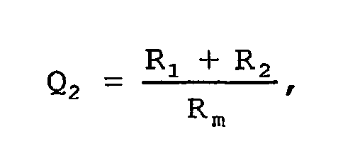
In einer alternativen Ausführung kann die erfindungsgemäße Vorrichtung mit geringen Modifikationen auch zur Ansteuerung von zwei Gleichstrommotoren, beispielsweise für ein Doppelkühlgebläse eines Kraftfahrzeugs, verwendet werden. Dazu ist das erste strombegrenzende Bauelement ein Widerstand und das zweite strombegrenzende Bauelement ein zweiter Gleichstrommotor, wobei nun der erste und der zweite Gleichstrommotor wahlweise jeweils einzeln oder in einer Reihenschaltung oder in einer Parallelschaltung betreibbar sind.In an alternative embodiment, the device according to the invention can also be used with slight modifications for driving two DC motors, for example for a double cooling fan of a motor vehicle. For this purpose, the first current-limiting component is a resistor and the second current-limiting component is a second DC motor, wherein now the first and the second DC motor are selectively operable either individually or in a series circuit or in a parallel circuit.
Die Beschaltung mittels der drei Schaltmittel erfolgt nun derart, dass ein erster Kontakt des ersten Gleichstrommotors mittels des ersten und des zweiten Schaltmittels über den Widerstand an eine Versorgungsspannung schaltbar ist, der erste Kontakt des ersten Gleichstrommotors mittels des zweiten und des dritten Schaltmittels an einen zweiten Kontakt des ersten Gleichstrommotors schaltbar ist, ein erster Kontakt des zweiten Gleichstrommotors mittels des ersten Schaltmittels über den Widerstand an die Versorgungsspannung und ein zweiter Kontakt des zweiten Gleichstrommotors mittels des dritten Schaltmittels an den zweiten Kontakt des ersten Gleichstrommotors schaltbar ist und der erste und der zweite Gleichstrommotor mittels des zweiten und des dritten Schaltmittels wahlweise in einer Reihen- oder Parallelschaltung schaltbar sind.The wiring by means of the three switching means is now such that a first contact of the first DC motor is switchable via the resistor to a supply voltage by means of the first and second switching means, the first contact of the first DC motor by means of the second and third switching means to a second contact the first DC motor is switchable, a first contact of the second DC motor by means of the first Switching means via the resistor to the supply voltage and a second contact of the second DC motor is switchable by means of the third switching means to the second contact of the first DC motor and the first and the second DC motor by means of the second and third switching means are selectively switchable in a series or parallel connection ,
Der Aufwand bzw. die Kosten für die erfindungsgemäße Vorrichtung zur stufenweisen Ansteuerung des Doppelkühlgebläses lässt sich weiter reduzieren, wenn der Widerstand nahezu einen Widerstandswert von Null Ohm besitzt. Dies ermöglicht zudem einen Betreib des ersten und/oder des zweiten Gleichstrommotors mit maximalem Drehmoment.The cost and the cost of the device according to the invention for the stepwise control of the double cooling fan can be further reduced if the resistance has almost a resistance value of zero ohms. This also allows operation of the first and / or the second DC motor with maximum torque.
Ein weiterer Vorteil der Erfindung ergibt sich, wenn mindestens einem Gleichstrommotor ein viertes Schaltmittel parallel geschaltet ist, da dieses im Falle seines Schließens ein zügiges Abbremsen des Gleichstrommotors nach Deaktivierung der erfindungsgemäßen Vorrichtung ermöglicht.A further advantage of the invention results when at least one DC motor, a fourth switching means is connected in parallel, since this allows a rapid deceleration of the DC motor after deactivation of the device according to the invention in the case of its closing.
Schließlich ist es vorteilhaft, wenn mindestens einem Schaltmittel ein thermisches Schutzelement zugeordnet ist, um eine Beschädigung der Gebläsemotoren durch einen zu hohen Strom zu vermeiden. Dazu kann den Schaltmitteln jeweils das thermische Schutzelement in den Steuerkreisen und/oder in den Lastkreisen vorgeschaltet sein.Finally, it is advantageous if at least one switching means is associated with a thermal protection element in order to avoid damage to the fan motors by too high a current. For this purpose, the switching means may each be preceded by the thermal protection element in the control circuits and / or in the load circuits.
Weitere Vorteile der Erfindung ergeben sich durch die in den abhängigen Ansprüchen angegebenen Merkmale sowie aus der Zeichnung und der nachfolgenden Beschreibung.Further advantages of the invention will become apparent from the features specified in the dependent claims and from the drawings and the description below.
Die Erfindung wird im Folgenden anhand der
-
Fig. 1 : ein Blockschaltbild eines ersten Ausführungsbeispiels der erfindungsgemäßen Vorrichtung, -
Fig. 2 : ein Diagramm der Drehzahl- und Kühlleistungskennlinien in Abhängigkeit von den unterschiedlichen Stufen der erfindungsgemäßen Vorrichtung nach dem ersten Ausführungsbeispiel, -
Fig. 3 : ein Blockschaltbild eines zweiten Ausführungsbeispiels der erfindungsgemäßen Vorrichtung sowie -
Fig. 4 : Blockschaltbilder einer Bremsschaltung (Fig. 4a ) und einer Schutzbeschaltung (Fig. 4b ) für die erfindungsgemäße Vorrichtung.
-
Fig. 1 FIG. 1 is a block diagram of a first embodiment of the device according to the invention, FIG. -
Fig. 2 FIG. 2: a diagram of the speed and cooling power characteristics as a function of the different stages of the device according to the invention according to the first embodiment, FIG. -
Fig. 3 a block diagram of a second embodiment of the device according to the invention and -
Fig. 4 : Block Diagrams of a Braking Circuit (Fig. 4a ) and a protective circuit (Fig. 4b ) for the device according to the invention.
In
Der erste Widerstand 18 ist mittels eines ersten Schaltmittels 22, das die beiden Schalterstellungen 0 (offen) und 1 (geschlossen) besitzt, an eine Versorgungsspannung Vcc und mittels eines zweiten Schaltmittels 24, das zwischen einer Position 0 und einer weiteren Position 1 umschaltbar ist, an einen ersten Kontakt 26 des Gleichstrommotors 12 schaltbar. Der zweite Widerstand 20 kann mittels eines dritten Schaltmittels 28, das wie das erste Schaltmittel 22 die beiden Schalterstellungen 0 (offen) und 1 (geschlossen) besitzt, über einen Knotenpunkt 30 an die Versorgungsspannung Vcc und mittels des zweiten Schaltmittels 24 an den ersten Kontakt 26 des Gleichstrommotors 12 geschaltet werden. Weiterhin ist es möglich, mittels des ersten und des dritten Schaltmittels 22 bzw. 28 den ersten und den zweiten Widerstand 18 und 20 in einer Parallelschaltung an die Versorgungsspannung Vcc und mittels des zweiten Schaltmittels 24 an den ersten Kontakt 26 des Gleichstrommotors 12 zu schalten. Schließlich können der erste und der zweite Widerstand 18 und 20 mittels des ersten und des zweiten Schaltmittels 22 bzw. 24 in einer Reihenschaltung an die Versorgungsspannung Vcc und an den ersten Kontakt 24 des Gleichstrommotors 12 geschaltet werden.The
Gemäß
Gemäß Tabelle 1 lassen sich nun mit den beiden Widerständen 18 und 20, die die Widerstandswerte R1 bzw. R2 aufweisen, und den drei Schaltmitteln 22, 24 und 28 fünf von Null verschiedene Kühlleistungsstufen einstellen, wobei der Gleichstrommotor 12 den mit Null gleichzusetzenden Ausschaltzustand (aus) einnimmt, wenn sich das erste und das dritte Schaltmittel 22 und 28 in der Position 0 befinden. Der Schaltzustand des zweiten Schaltmittels 24 spielt in dieser Stufe keine Rolle und ist daher mit einem * bezeichnet.
Eine geringe Kühlleistung (gering) ergibt sich, wenn das erste Schaltmittel 22 in Position 1 geschaltet wird und das zweite und dritte Schaltmittel sich jeweils in der Position 0 befinden. Diese Schalterstellung bewirkt eine Reihenschaltung der beiden Widerstände 18 und 20, so dass sich ein resultierender Widerstandswert R1 + R2 ergibt, der einen verhältnismäßig hohen Spannungsabfall über der Reihenschaltung bewirkt. Eine erste mittlere Kühlleistung (mittel 1) folgt aus den Positionen 1 des ersten Schaltmittels 22, 1 des zweiten Schaltmittels 24 und 0 des dritten Schaltmittels 28. In diesem Fall sieht der Gleichstrommotor 12 lediglich den Widerstandswert R1 des ersten Widerstands 18. Werden dagegen das erste Schaltmittel 22 auf Position 0 und die beiden übrigen Schaltmittel 24 und 28 jeweils auf Position 1 gesetzt, so ergibt sich eine zweite mittlere Kühlleistung (mittel 2) mit einem resultierenden Widerstandswert R2. Eine dritte mittlere Kühlleistung (mittel 3) ist einstellbar, wenn sich alle drei Schaltmittel 22, 24 und 28 jeweils in ihrer Position 1 befinden, so dass sich eine Parallelschaltung der beiden Widerstände 18 und 20 mit einem resultierenden Widerstandswert R1 | | R2 = R1 · R2/(R1 + R2) ergibt. Befinden sich schließlich das zweite Schaltmittel 24 auf Position 0 und das dritte Schaltmittel 28 auf Position 1, so sind beide Widerstände 18 und 20 überbrückt und der Gleichstrommotor 12 läuft mit der höchsten Drehzahl, was wiederum eine hohe Kühlleistung zur Folge hat. Die Schalterstellung des ersten Schaltmittels 22 ist in diesem Fall redundant und daher mit einem * gekennzeichnet.


In
Die Vorrichtung 10 ist nun derart ausgebildet, dass der erste Kontakt 26 des ersten Gleichstrommotors 12 mittels des ersten und des zweiten Schaltmittels 22 und 24 über den Widerstand 46 an die Versorgungsspannung Vcc schaltbar ist. Weiterhin lässt sich der erste Kontakt 26 des ersten Gleichstrommotors 12 mittels des zweiten und des dritten Schaltmittels 24 bzw. 28 an den zweiten Kontakt 32 des ersten Gleichstrommotors 12 schalten. Darüber hinaus sind der erste Kontakt 50 des zweiten Gleichstrommotors 48 mittels des ersten Schaltmittels 22 über den Widerstand 46 an die Versorgungsspannung Vcc und der zweite Kontakt 52 des zweiten Gleichstrommotors 48 mittels des dritten Schaltmittels 28 an den zweiten Kontakt 32 des ersten Gleichstrommotors 12 schaltbar. Schließlich ist es möglich, den ersten und den zweiten Gleichstrommotor 12 und 48 mittels des zweiten und des dritten Schaltmittels 24 bzw. 28 wahlweise in einer Reihen- oder Parallelschaltung zu betreiben.The
Der Widerstand 46 kann beispielsweise einen sehr kleinen Widerstandswert R aufweisen und als Shunt zur Strommessung verwendet werden. Ebenso kann R aber auch einen Wert von nahezu Null Ohm aufweisen, so dass das erste Bauelement 14 einer Brücke entspricht.The
In der nachfolgenden Tabelle 2 sind die mit der Vorrichtung 10 gemäß dem zweiten Ausführungsbeispiel erzielbaren Stufen für die Kühlleistung des Doppelgebläses aufgezeigt. Danach ergibt sich der Ausschaltzustand (aus) des Doppelgebläses, wenn das erste Schaltmittel 22 auf die Position 0 (geöffnet) geschaltet ist. Die Positionen der beiden übrigen Schaltmittel 24 und 28 sind in diesem Fall redundant und daher mit einem * gekennzeichnet. Das Doppelgebläse wird in Betrieb gesetzt durch Verbringen des ersten Schaltmittels 22 in die Position 1 (geschlossen), wobei nun vier von Null verschiedene Stufen in Abhängigkeit der Positionen des zweiten und des dritten Schaltmittels 24 bzw. 28 schaltbar sind.
Eine erste mittlere Kühlleistung (mittel 1) lässt sich zum Beispiel durch Position 0 des zweiten Schaltmittels 24 und Position 1 des dritten Schaltmittels 28 erreichen. Dies hat zur Folge, dass nur der zweite Gleichstrommotor 48 in Betrieb ist. Bringt man dagegen das zweite Schaltmittel 24 in Position 1 und das dritte Schaltmittel 28 in Position 0, so läuft nur der erste Gleichstrommotor 12, was zu einer zweiten mittleren Kühlleistung (mittel 2) führt. Eine dritte mittlere Kühlleistung (mittel 3) resultiert aus dem Schalten des zweiten und des dritten Schaltmittels 24 und 28 jeweils in ihre Position 0, da nun beide Gleichstrommotoren 12 und 48 in einer Reihenschaltung betrieben werden. Verbringt man schließlich jeweils das zweite und das dritte Schaltmittel 24 bzw. 48 in ihre Position 1, so arbeiten beide Gleichstrommotoren 12 und 48 in einer Parallelschaltung und bewirken eine hohe Kühlleistung (hoch).A first average cooling capacity (average 1) can be achieved, for example, by
In
Es sei abschließend noch darauf hingewiesen, dass die gezeigten Ausführungsbeispiele weder auf die
Claims (14)
- Apparatus (10) for driving, in stages, at least one first DC motor (12) for a cooling fan of a motor vehicle, having a first (14) and a second current-limiting component (16) and having a first (22), a second (24) and a third switching means (28), characterized in that the switching means (22, 24, 28) interconnect the first (14) and the second current-limiting component (16) in such a way that a cooling power of the cooling fan can be varied in at least four stages which are different from zero, with the first and the third switching means (22, 28) being in the form of an off/on switch and the second switching means (24) being in the form of a changeover switch with in each case a first switch position (0) and a second switch position (1).
- Apparatus according to Claim 1, characterized in that the first (14) and the second current-limiting component (16) can selectively be operated in each case individually or in a series circuit or in a parallel circuit.
- Apparatus according to Claim 1 or 2, characterized in that- the first current-limiting component (14) can be connected to a supply voltage (Vcc) by means of the first switching means (22) and can be connected to a first contact (26) of the DC motor (12) by means of the second switching means (24),- the second current-limiting component (16) can be connected to the supply voltage (Vcc) by means of the third switching means (28) and can be connected to the first contact (26) of the DC motor (12) by means of the second switching means (24),- the first (14) and the second current-limiting component (16) can be connected to the supply voltage (Vcc) by means of the first (22) and the third switching means (28) in a parallel circuit and can be connected to the first contact (26) of the DC motor (12) by means of the second switching means (24), and- the first (14) and the second current-limiting component (16) can be connected to the supply voltage (Vcc) and to the first contact (26) of the DC motor (12) by means of the first (22) and the second switching means (24) in a series circuit.
- Apparatus according to one of the preceding claims, characterized in that the first current-limiting component (14) is a first resistor (18) and the second current-limiting component (16) is a second resistor (20).
- Apparatus according to Claim 4, characterized in that the first resistor (18) has a first resistance value R1 and the second resistor (20) has a second resistance value R2, and in that a first quotient

- Apparatus according to Claim 5, characterized in that the first quotient Q1 assumes the approximate value of 62%.
- Apparatus according to Claim 4, characterized in that the at least one DC motor (12) has a motor resistance value Rm, and in that a second quotient

- Apparatus according to Claim 1, characterized in that the first current-limiting component (14) is a resistor (46) and the second current-limiting component (16) is a second DC motor (48).
- Apparatus according to Claim 8, characterized in that the first (12) and the second DC motor (48) can selectively be operated in each case individually or in a series circuit or in a parallel circuit.
- Apparatus according to Claim 8 or 9, characterized in that- a first contact (26) of the first DC motor (12) can be connected to a supply voltage (Vcc) via the resistor (46) by means of the first (22) and the second switching means (24),- the first contact (26) of the first DC motor (12) can be connected to a second contact (32) of the first DC motor (12) by means of the second (24) and the third switching means (28),- a first contact (50) of the second DC motor (48) can be connected to the supply voltage (Vcc) via the resistor (46) by means of the first switching means (22), and a second contact (52) of the second DC motor (48) can be connected to the second contact (32) of the first DC motor (12) by means of the third switching means (28),- the first (12) and the second DC motor (148) can selectively be connected in a series or parallel circuit by means of the second (24) and the third switching means (28).
- Apparatus according to one of the preceding Claims 8 to 10, characterized in that the resistor (46) has a resistance value of R ≈ 0 ohm.
- Apparatus according to one of the preceding claims, characterized in that at least one switching means (22, 24, 28) in each case has an associated thermal protection element (70).
- Apparatus according to one of the preceding claims, characterized in that the switching means (22, 24, 28) are designed as relays (60) and/or MOSFET and/or FET and/or bipolar transistors.
- Apparatus according to one of the preceding claims, characterized in that a fourth switching means (56) is connected in parallel with the at least one DC motor (12, 48).
Applications Claiming Priority (2)
| Application Number | Priority Date | Filing Date | Title |
|---|---|---|---|
| DE102004046900A DE102004046900A1 (en) | 2004-09-28 | 2004-09-28 | Device for the stepwise control of a DC motor for a cooling fan of a motor vehicle |
| PCT/EP2004/053164 WO2006034733A1 (en) | 2004-09-28 | 2004-11-30 | Device for the incremental control of a direct-current motor for the cooling fan of a motor vehicle |
Publications (2)
| Publication Number | Publication Date |
|---|---|
| EP1797635A1 EP1797635A1 (en) | 2007-06-20 |
| EP1797635B1 true EP1797635B1 (en) | 2009-06-10 |
Family
ID=34959465
Family Applications (1)
| Application Number | Title | Priority Date | Filing Date |
|---|---|---|---|
| EP04804606A Expired - Fee Related EP1797635B1 (en) | 2004-09-28 | 2004-11-30 | Device for the incremental control of a direct-current motor for the cooling fan of a motor vehicle |
Country Status (8)
| Country | Link |
|---|---|
| US (1) | US7683561B2 (en) |
| EP (1) | EP1797635B1 (en) |
| JP (1) | JP4575453B2 (en) |
| KR (1) | KR101043194B1 (en) |
| CN (1) | CN101027835B (en) |
| DE (2) | DE102004046900A1 (en) |
| ES (1) | ES2327644T3 (en) |
| WO (1) | WO2006034733A1 (en) |
Families Citing this family (4)
| Publication number | Priority date | Publication date | Assignee | Title |
|---|---|---|---|---|
| TWI410040B (en) * | 2008-09-02 | 2013-09-21 | Anpec Electronics Corp | Motor driving circuit for adjusting speed of the motor by changing output voltage |
| DE102011088976A1 (en) * | 2011-01-31 | 2012-08-02 | Continental Automotive Gmbh | Arrangement for controlling an electric vacuum pump |
| DE102016216041A1 (en) * | 2016-08-25 | 2018-03-01 | Robert Bosch Gmbh | Method and control device for heating a device driven by a brushless DC motor |
| CN111301111B (en) * | 2018-12-12 | 2023-12-29 | 上海汽车集团股份有限公司 | Vehicle heating wire preheating circuit, control method and control device |
Family Cites Families (19)
| Publication number | Priority date | Publication date | Assignee | Title |
|---|---|---|---|---|
| DE1912613B2 (en) * | 1969-03-12 | 1976-07-22 | Süddeutsche Kühlerfabrik Julius Fr. Behr, 7000 Stuttgart | DEVICE FOR THE INDEPENDENT REGULATION OF THE FAN FOR THE FORCED VENTILATION OF HEAT EXCHANGERS |
| JPS5269750U (en) * | 1975-11-19 | 1977-05-24 | ||
| JPS5550813U (en) * | 1978-09-29 | 1980-04-03 | ||
| JPS5550813A (en) | 1978-10-12 | 1980-04-14 | Iseki Agricult Mach | Threshing drum of threshing device |
| DE2904904A1 (en) * | 1979-02-09 | 1980-08-21 | Bosch Gmbh Robert | DC MOTOR |
| JPS6192192A (en) * | 1984-10-12 | 1986-05-10 | Nissan Motor Co Ltd | Motor controller for vehicle |
| DE3543207A1 (en) | 1985-12-06 | 1987-06-11 | Audi Ag | Control circuit for a radiator fan in a motor vehicle |
| DE3711392C1 (en) * | 1987-04-04 | 1989-01-12 | Behr Thomson Dehnstoffregler | Cooling device for an internal combustion engine and method for controlling such a cooling device |
| FR2658962B1 (en) | 1990-02-26 | 1995-04-14 | Valeo Thermique Moteur Sa | SPEED SWITCHING DEVICE FOR A CONSTANT FLOW MULTIPOLAR ELECTRIC MOTOR, AND MOTOR - VENTILATOR GROUP THEREOF. |
| US4988930A (en) * | 1990-04-25 | 1991-01-29 | Oberheide George C | Plural motor fan system with improved speed control |
| DE9013386U1 (en) | 1990-09-21 | 1990-11-22 | Siemens Ag, 8000 Muenchen, De | |
| GB9112618D0 (en) | 1991-06-12 | 1991-07-31 | Racal Safety Ltd | Dc motor control |
| EP0877473B1 (en) * | 1994-06-10 | 2005-01-12 | Omron Corporation | DC motor control circuit |
| US6037732A (en) * | 1996-11-14 | 2000-03-14 | Telcom Semiconductor, Inc. | Intelligent power management for a variable speed fan |
| IT1305093B1 (en) | 1998-12-30 | 2001-04-10 | Fiat Auto Spa | STARTING PHASE CONTROL DEVICE OF AN ELECTRIC MOTOR. |
| US6351601B1 (en) * | 1999-02-24 | 2002-02-26 | Micrel Incorporated | Fan speed control system having an integrated circuit fan controller and a method of using the same |
| US6368064B1 (en) * | 2000-12-01 | 2002-04-09 | 3Com Corporation | Apparatus and method of providing redundant power and redundant fan speed control to a plurality of fans |
| DE10121766A1 (en) * | 2001-05-04 | 2002-11-21 | Bosch Gmbh Robert | power unit |
| EP1375326A3 (en) * | 2002-06-04 | 2005-07-06 | Rodriguez Martinez, S.C. | Automatic progressive accelerator for children's electric vehicles |
-
2004
- 2004-09-28 DE DE102004046900A patent/DE102004046900A1/en not_active Ceased
- 2004-11-30 EP EP04804606A patent/EP1797635B1/en not_active Expired - Fee Related
- 2004-11-30 CN CN2004800440877A patent/CN101027835B/en not_active Expired - Fee Related
- 2004-11-30 KR KR1020077007060A patent/KR101043194B1/en not_active IP Right Cessation
- 2004-11-30 JP JP2007533878A patent/JP4575453B2/en not_active Expired - Fee Related
- 2004-11-30 WO PCT/EP2004/053164 patent/WO2006034733A1/en active Application Filing
- 2004-11-30 US US11/571,903 patent/US7683561B2/en not_active Expired - Fee Related
- 2004-11-30 DE DE502004009598T patent/DE502004009598D1/en active Active
- 2004-11-30 ES ES04804606T patent/ES2327644T3/en active Active
Also Published As
| Publication number | Publication date |
|---|---|
| KR20070072863A (en) | 2007-07-06 |
| US20080002953A1 (en) | 2008-01-03 |
| ES2327644T3 (en) | 2009-11-02 |
| CN101027835B (en) | 2011-01-12 |
| US7683561B2 (en) | 2010-03-23 |
| DE102004046900A1 (en) | 2006-04-20 |
| CN101027835A (en) | 2007-08-29 |
| KR101043194B1 (en) | 2011-06-22 |
| DE502004009598D1 (en) | 2009-07-23 |
| JP4575453B2 (en) | 2010-11-04 |
| JP2008515375A (en) | 2008-05-08 |
| EP1797635A1 (en) | 2007-06-20 |
| WO2006034733A1 (en) | 2006-04-06 |
Similar Documents
| Publication | Publication Date | Title |
|---|---|---|
| DE10151177B4 (en) | Device for controlling a motor-driven power steering device | |
| DE2822315C2 (en) | ||
| DE2147394C2 (en) | Control for regulating centrifugal compressors for a cooling system | |
| DE102017107076A1 (en) | Power tool and motor driver system thereof | |
| DE3044150C2 (en) | Additional device for a standard voltage regulator of a motor vehicle alternator | |
| EP1797635B1 (en) | Device for the incremental control of a direct-current motor for the cooling fan of a motor vehicle | |
| EP0350783A2 (en) | Device for operating loads connected to a direct current power supply system of a mobile unit | |
| WO2002091560A1 (en) | Drive unit | |
| EP0601352B1 (en) | Braking device for a series commutator motor | |
| DE1929551A1 (en) | High-voltage disconnector with upstream resistors | |
| EP0374288B1 (en) | Integrated circuit diminishing the inverse current of an inversely polarized transistor | |
| DE2019184C3 (en) | Heavy current switchgear | |
| DE1538714A1 (en) | Control system for electric motors | |
| DE3428585A1 (en) | Seat adjuster having a motor drive for vehicle seats | |
| DE2726696B2 (en) | Electrical protection circuitry | |
| DE2258862A1 (en) | CONTROL CIRCUIT FOR RAPID EXCITATION OF ELECTROMAGNETIC SYSTEMS, IN PARTICULAR OF A STEPPER MOTOR | |
| EP0863604A1 (en) | Method and device for controlling and/or regulating a retarder used as vehicle auxiliary brake | |
| DE1690549A1 (en) | Device for determining the operating status of an electric arc furnace | |
| EP3891891B1 (en) | Switch module for an electrical switch | |
| DE3340891C2 (en) | ||
| EP3387749B1 (en) | High-side switch for supplying power to at least one sensor | |
| EP1630947B1 (en) | Method for determining the load current | |
| EP4285478A1 (en) | Electronics unit for an electrical device | |
| DE1613200C (en) | Antnebsanlage with one or more DC motors fed with constant current | |
| EP0895357B1 (en) | PWM switching power output stage for controlling and regulating inductive loads |
Legal Events
| Date | Code | Title | Description |
|---|---|---|---|
| PUAI | Public reference made under article 153(3) epc to a published international application that has entered the european phase |
Free format text: ORIGINAL CODE: 0009012 |
|
| 17P | Request for examination filed |
Effective date: 20070502 |
|
| AK | Designated contracting states |
Kind code of ref document: A1 Designated state(s): DE ES FR GB SE |
|
| DAX | Request for extension of the european patent (deleted) | ||
| RBV | Designated contracting states (corrected) |
Designated state(s): DE ES FR GB SE |
|
| GRAP | Despatch of communication of intention to grant a patent |
Free format text: ORIGINAL CODE: EPIDOSNIGR1 |
|
| GRAS | Grant fee paid |
Free format text: ORIGINAL CODE: EPIDOSNIGR3 |
|
| GRAA | (expected) grant |
Free format text: ORIGINAL CODE: 0009210 |
|
| AK | Designated contracting states |
Kind code of ref document: B1 Designated state(s): DE ES FR GB SE |
|
| REG | Reference to a national code |
Ref country code: GB Ref legal event code: FG4D Free format text: NOT ENGLISH |
|
| REF | Corresponds to: |
Ref document number: 502004009598 Country of ref document: DE Date of ref document: 20090723 Kind code of ref document: P |
|
| REG | Reference to a national code |
Ref country code: SE Ref legal event code: TRGR |
|
| REG | Reference to a national code |
Ref country code: ES Ref legal event code: FG2A Ref document number: 2327644 Country of ref document: ES Kind code of ref document: T3 |
|
| PLBE | No opposition filed within time limit |
Free format text: ORIGINAL CODE: 0009261 |
|
| STAA | Information on the status of an ep patent application or granted ep patent |
Free format text: STATUS: NO OPPOSITION FILED WITHIN TIME LIMIT |
|
| 26N | No opposition filed |
Effective date: 20100311 |
|
| PGFP | Annual fee paid to national office [announced via postgrant information from national office to epo] |
Ref country code: GB Payment date: 20101123 Year of fee payment: 7 |
|
| PGFP | Annual fee paid to national office [announced via postgrant information from national office to epo] |
Ref country code: SE Payment date: 20111122 Year of fee payment: 8 |
|
| REG | Reference to a national code |
Ref country code: DE Ref legal event code: R084 Ref document number: 502004009598 Country of ref document: DE Effective date: 20120201 |
|
| PGFP | Annual fee paid to national office [announced via postgrant information from national office to epo] |
Ref country code: ES Payment date: 20121122 Year of fee payment: 9 |
|
| PGFP | Annual fee paid to national office [announced via postgrant information from national office to epo] |
Ref country code: FR Payment date: 20121217 Year of fee payment: 9 |
|
| GBPC | Gb: european patent ceased through non-payment of renewal fee |
Effective date: 20121130 |
|
| PG25 | Lapsed in a contracting state [announced via postgrant information from national office to epo] |
Ref country code: SE Free format text: LAPSE BECAUSE OF NON-PAYMENT OF DUE FEES Effective date: 20121201 |
|
| PG25 | Lapsed in a contracting state [announced via postgrant information from national office to epo] |
Ref country code: GB Free format text: LAPSE BECAUSE OF NON-PAYMENT OF DUE FEES Effective date: 20121130 |
|
| PGFP | Annual fee paid to national office [announced via postgrant information from national office to epo] |
Ref country code: DE Payment date: 20140124 Year of fee payment: 10 |
|
| REG | Reference to a national code |
Ref country code: FR Ref legal event code: ST Effective date: 20140731 |
|
| PG25 | Lapsed in a contracting state [announced via postgrant information from national office to epo] |
Ref country code: FR Free format text: LAPSE BECAUSE OF NON-PAYMENT OF DUE FEES Effective date: 20131202 |
|
| REG | Reference to a national code |
Ref country code: ES Ref legal event code: FD2A Effective date: 20150407 |
|
| PG25 | Lapsed in a contracting state [announced via postgrant information from national office to epo] |
Ref country code: ES Free format text: LAPSE BECAUSE OF NON-PAYMENT OF DUE FEES Effective date: 20131201 |
|
| REG | Reference to a national code |
Ref country code: DE Ref legal event code: R119 Ref document number: 502004009598 Country of ref document: DE |
|
| PG25 | Lapsed in a contracting state [announced via postgrant information from national office to epo] |
Ref country code: DE Free format text: LAPSE BECAUSE OF NON-PAYMENT OF DUE FEES Effective date: 20150602 |