EP1796818B1 - Grooved active and passive adsorbent filters - Google Patents
Grooved active and passive adsorbent filters Download PDFInfo
- Publication number
- EP1796818B1 EP1796818B1 EP05849734.8A EP05849734A EP1796818B1 EP 1796818 B1 EP1796818 B1 EP 1796818B1 EP 05849734 A EP05849734 A EP 05849734A EP 1796818 B1 EP1796818 B1 EP 1796818B1
- Authority
- EP
- European Patent Office
- Prior art keywords
- adsorbent
- media
- assembly
- filter
- layer
- Prior art date
- Legal status (The legal status is an assumption and is not a legal conclusion. Google has not performed a legal analysis and makes no representation as to the accuracy of the status listed.)
- Active
Links
- 239000003463 adsorbent Substances 0.000 title claims description 266
- 239000010410 layer Substances 0.000 claims description 180
- 239000000853 adhesive Substances 0.000 claims description 53
- 230000001070 adhesive effect Effects 0.000 claims description 52
- 239000000463 material Substances 0.000 claims description 45
- 239000002245 particle Substances 0.000 claims description 45
- 239000012528 membrane Substances 0.000 claims description 31
- 229920001343 polytetrafluoroethylene Polymers 0.000 claims description 31
- 239000004810 polytetrafluoroethylene Substances 0.000 claims description 31
- 239000000356 contaminant Substances 0.000 claims description 28
- OKTJSMMVPCPJKN-UHFFFAOYSA-N Carbon Chemical compound [C] OKTJSMMVPCPJKN-UHFFFAOYSA-N 0.000 claims description 27
- 239000012790 adhesive layer Substances 0.000 claims description 24
- 238000009792 diffusion process Methods 0.000 claims description 24
- 238000001914 filtration Methods 0.000 claims description 24
- 239000012530 fluid Substances 0.000 claims description 14
- KWYUFKZDYYNOTN-UHFFFAOYSA-M Potassium hydroxide Chemical compound [OH-].[K+] KWYUFKZDYYNOTN-UHFFFAOYSA-M 0.000 claims description 9
- 230000002209 hydrophobic effect Effects 0.000 claims description 9
- 239000000835 fiber Substances 0.000 claims description 8
- 238000004891 communication Methods 0.000 claims description 7
- VTYYLEPIZMXCLO-UHFFFAOYSA-L Calcium carbonate Chemical compound [Ca+2].[O-]C([O-])=O VTYYLEPIZMXCLO-UHFFFAOYSA-L 0.000 claims description 6
- CDBYLPFSWZWCQE-UHFFFAOYSA-L Sodium Carbonate Chemical compound [Na+].[Na+].[O-]C([O-])=O CDBYLPFSWZWCQE-UHFFFAOYSA-L 0.000 claims description 6
- OSGAYBCDTDRGGQ-UHFFFAOYSA-L calcium sulfate Chemical compound [Ca+2].[O-]S([O-])(=O)=O OSGAYBCDTDRGGQ-UHFFFAOYSA-L 0.000 claims description 6
- BWHMMNNQKKPAPP-UHFFFAOYSA-L potassium carbonate Chemical compound [K+].[K+].[O-]C([O-])=O BWHMMNNQKKPAPP-UHFFFAOYSA-L 0.000 claims description 6
- 239000004820 Pressure-sensitive adhesive Substances 0.000 claims description 5
- VYPSYNLAJGMNEJ-UHFFFAOYSA-N Silicium dioxide Chemical compound O=[Si]=O VYPSYNLAJGMNEJ-UHFFFAOYSA-N 0.000 claims description 3
- PNEYBMLMFCGWSK-UHFFFAOYSA-N aluminium oxide Inorganic materials [O-2].[O-2].[O-2].[Al+3].[Al+3] PNEYBMLMFCGWSK-UHFFFAOYSA-N 0.000 claims description 3
- 229910000019 calcium carbonate Inorganic materials 0.000 claims description 3
- 239000008187 granular material Substances 0.000 claims description 3
- 238000000034 method Methods 0.000 claims description 3
- 239000002808 molecular sieve Substances 0.000 claims description 3
- 239000004745 nonwoven fabric Substances 0.000 claims description 3
- 229920000642 polymer Polymers 0.000 claims description 3
- 229910000027 potassium carbonate Inorganic materials 0.000 claims description 3
- 239000012286 potassium permanganate Substances 0.000 claims description 3
- 239000000741 silica gel Substances 0.000 claims description 3
- 229910002027 silica gel Inorganic materials 0.000 claims description 3
- URGAHOPLAPQHLN-UHFFFAOYSA-N sodium aluminosilicate Chemical compound [Na+].[Al+3].[O-][Si]([O-])=O.[O-][Si]([O-])=O URGAHOPLAPQHLN-UHFFFAOYSA-N 0.000 claims description 3
- 229910000029 sodium carbonate Inorganic materials 0.000 claims description 3
- 239000004831 Hot glue Substances 0.000 claims description 2
- 230000037361 pathway Effects 0.000 claims 2
- 239000004593 Epoxy Substances 0.000 claims 1
- 125000003700 epoxy group Chemical group 0.000 claims 1
- 229920000647 polyepoxide Polymers 0.000 claims 1
- 238000010276 construction Methods 0.000 description 16
- 238000011109 contamination Methods 0.000 description 11
- XLYOFNOQVPJJNP-UHFFFAOYSA-N water Chemical compound O XLYOFNOQVPJJNP-UHFFFAOYSA-N 0.000 description 11
- -1 polytetrafluoroethylene Polymers 0.000 description 9
- 229910001868 water Inorganic materials 0.000 description 9
- 239000002594 sorbent Substances 0.000 description 8
- 238000012360 testing method Methods 0.000 description 8
- 230000000052 comparative effect Effects 0.000 description 7
- 238000001179 sorption measurement Methods 0.000 description 7
- 229910052799 carbon Inorganic materials 0.000 description 6
- 229920000728 polyester Polymers 0.000 description 6
- 230000003134 recirculating effect Effects 0.000 description 6
- 239000004743 Polypropylene Substances 0.000 description 5
- RAHZWNYVWXNFOC-UHFFFAOYSA-N Sulphur dioxide Chemical class O=S=O RAHZWNYVWXNFOC-UHFFFAOYSA-N 0.000 description 5
- 239000011230 binding agent Substances 0.000 description 5
- 239000000203 mixture Substances 0.000 description 5
- 229920001155 polypropylene Polymers 0.000 description 5
- 150000003839 salts Chemical class 0.000 description 5
- 239000012808 vapor phase Substances 0.000 description 5
- 239000000945 filler Substances 0.000 description 4
- 239000002356 single layer Substances 0.000 description 4
- 239000000758 substrate Substances 0.000 description 4
- 238000005406 washing Methods 0.000 description 4
- 230000004584 weight gain Effects 0.000 description 4
- 235000019786 weight gain Nutrition 0.000 description 4
- ZAMOUSCENKQFHK-UHFFFAOYSA-N Chlorine atom Chemical compound [Cl] ZAMOUSCENKQFHK-UHFFFAOYSA-N 0.000 description 3
- HEMHJVSKTPXQMS-UHFFFAOYSA-M Sodium hydroxide Chemical compound [OH-].[Na+] HEMHJVSKTPXQMS-UHFFFAOYSA-M 0.000 description 3
- 229910052782 aluminium Inorganic materials 0.000 description 3
- XAGFODPZIPBFFR-UHFFFAOYSA-N aluminium Chemical compound [Al] XAGFODPZIPBFFR-UHFFFAOYSA-N 0.000 description 3
- 239000000460 chlorine Substances 0.000 description 3
- 235000019398 chlorine dioxide Nutrition 0.000 description 3
- 239000002131 composite material Substances 0.000 description 3
- 230000007797 corrosion Effects 0.000 description 3
- 238000005260 corrosion Methods 0.000 description 3
- 239000008367 deionised water Substances 0.000 description 3
- 229910021641 deionized water Inorganic materials 0.000 description 3
- 238000013461 design Methods 0.000 description 3
- 238000011068 loading method Methods 0.000 description 3
- 230000007246 mechanism Effects 0.000 description 3
- 238000010943 off-gassing Methods 0.000 description 3
- 230000003287 optical effect Effects 0.000 description 3
- 239000004033 plastic Substances 0.000 description 3
- 229920003023 plastic Polymers 0.000 description 3
- 239000011148 porous material Substances 0.000 description 3
- NLKNQRATVPKPDG-UHFFFAOYSA-M potassium iodide Chemical compound [K+].[I-] NLKNQRATVPKPDG-UHFFFAOYSA-M 0.000 description 3
- 238000012545 processing Methods 0.000 description 3
- 239000000126 substance Substances 0.000 description 3
- 235000010269 sulphur dioxide Nutrition 0.000 description 3
- NHTMVDHEPJAVLT-UHFFFAOYSA-N Isooctane Chemical compound CC(C)CC(C)(C)C NHTMVDHEPJAVLT-UHFFFAOYSA-N 0.000 description 2
- 239000004952 Polyamide Substances 0.000 description 2
- 239000004698 Polyethylene Substances 0.000 description 2
- 239000003522 acrylic cement Substances 0.000 description 2
- 239000004676 acrylonitrile butadiene styrene Substances 0.000 description 2
- 239000002390 adhesive tape Substances 0.000 description 2
- OSVXSBDYLRYLIG-UHFFFAOYSA-N chlorine dioxide Inorganic materials O=Cl=O OSVXSBDYLRYLIG-UHFFFAOYSA-N 0.000 description 2
- 238000009434 installation Methods 0.000 description 2
- 150000002500 ions Chemical class 0.000 description 2
- 239000000314 lubricant Substances 0.000 description 2
- 238000004519 manufacturing process Methods 0.000 description 2
- 229920002647 polyamide Polymers 0.000 description 2
- 239000004417 polycarbonate Substances 0.000 description 2
- 229920000515 polycarbonate Polymers 0.000 description 2
- 229920000573 polyethylene Polymers 0.000 description 2
- 230000009467 reduction Effects 0.000 description 2
- 238000011160 research Methods 0.000 description 2
- 230000003068 static effect Effects 0.000 description 2
- FLTJDUOFAQWHDF-UHFFFAOYSA-N trimethyl pentane Natural products CCCCC(C)(C)C FLTJDUOFAQWHDF-UHFFFAOYSA-N 0.000 description 2
- 239000011800 void material Substances 0.000 description 2
- AQWSFUIGRSMCST-UHFFFAOYSA-N 3-pyridin-3-ylsulfonyl-5-(trifluoromethyl)chromen-2-one Chemical compound N1=CC(=CC=C1)S(=O)(=O)C=1C(OC2=CC=CC(=C2C=1)C(F)(F)F)=O AQWSFUIGRSMCST-UHFFFAOYSA-N 0.000 description 1
- 241000723418 Carya Species 0.000 description 1
- 238000005629 Voight synthesis reaction Methods 0.000 description 1
- 239000002253 acid Substances 0.000 description 1
- NIXOWILDQLNWCW-UHFFFAOYSA-N acrylic acid group Chemical group C(C=C)(=O)O NIXOWILDQLNWCW-UHFFFAOYSA-N 0.000 description 1
- 229920006397 acrylic thermoplastic Polymers 0.000 description 1
- XECAHXYUAAWDEL-UHFFFAOYSA-N acrylonitrile butadiene styrene Chemical compound C=CC=C.C=CC#N.C=CC1=CC=CC=C1 XECAHXYUAAWDEL-UHFFFAOYSA-N 0.000 description 1
- 229920000122 acrylonitrile butadiene styrene Polymers 0.000 description 1
- 239000011149 active material Substances 0.000 description 1
- 230000002411 adverse Effects 0.000 description 1
- 230000004888 barrier function Effects 0.000 description 1
- 239000011324 bead Substances 0.000 description 1
- 238000005452 bending Methods 0.000 description 1
- 230000009286 beneficial effect Effects 0.000 description 1
- 230000005540 biological transmission Effects 0.000 description 1
- 230000003139 buffering effect Effects 0.000 description 1
- AXCZMVOFGPJBDE-UHFFFAOYSA-L calcium dihydroxide Chemical compound [OH-].[OH-].[Ca+2] AXCZMVOFGPJBDE-UHFFFAOYSA-L 0.000 description 1
- 239000000920 calcium hydroxide Substances 0.000 description 1
- 229910001861 calcium hydroxide Inorganic materials 0.000 description 1
- 238000005266 casting Methods 0.000 description 1
- 239000001913 cellulose Substances 0.000 description 1
- 229920002678 cellulose Polymers 0.000 description 1
- 239000000919 ceramic Substances 0.000 description 1
- 230000008859 change Effects 0.000 description 1
- 229910052801 chlorine Inorganic materials 0.000 description 1
- 150000001875 compounds Chemical class 0.000 description 1
- 230000006835 compression Effects 0.000 description 1
- 238000007906 compression Methods 0.000 description 1
- 238000004883 computer application Methods 0.000 description 1
- 230000007812 deficiency Effects 0.000 description 1
- 238000001035 drying Methods 0.000 description 1
- 230000009977 dual effect Effects 0.000 description 1
- 238000010410 dusting Methods 0.000 description 1
- 230000000694 effects Effects 0.000 description 1
- 230000005611 electricity Effects 0.000 description 1
- 238000005516 engineering process Methods 0.000 description 1
- 239000003344 environmental pollutant Substances 0.000 description 1
- 238000011067 equilibration Methods 0.000 description 1
- 238000011049 filling Methods 0.000 description 1
- 239000011888 foil Substances 0.000 description 1
- 231100001261 hazardous Toxicity 0.000 description 1
- 238000010438 heat treatment Methods 0.000 description 1
- 230000003116 impacting effect Effects 0.000 description 1
- 238000003475 lamination Methods 0.000 description 1
- 239000004816 latex Substances 0.000 description 1
- 229920000126 latex Polymers 0.000 description 1
- 239000007788 liquid Substances 0.000 description 1
- 238000013507 mapping Methods 0.000 description 1
- 239000011159 matrix material Substances 0.000 description 1
- 239000011140 metalized polyester Substances 0.000 description 1
- 238000005065 mining Methods 0.000 description 1
- 150000002894 organic compounds Chemical class 0.000 description 1
- 238000012856 packing Methods 0.000 description 1
- 230000035699 permeability Effects 0.000 description 1
- 239000012071 phase Substances 0.000 description 1
- 231100000719 pollutant Toxicity 0.000 description 1
- 229920003229 poly(methyl methacrylate) Polymers 0.000 description 1
- 239000012255 powdered metal Substances 0.000 description 1
- 239000011241 protective layer Substances 0.000 description 1
- 239000000376 reactant Substances 0.000 description 1
- 239000011347 resin Substances 0.000 description 1
- 229920005989 resin Polymers 0.000 description 1
- 230000002000 scavenging effect Effects 0.000 description 1
- 238000007789 sealing Methods 0.000 description 1
- 239000004065 semiconductor Substances 0.000 description 1
- 230000035945 sensitivity Effects 0.000 description 1
- 238000007873 sieving Methods 0.000 description 1
- 238000000638 solvent extraction Methods 0.000 description 1
- 238000003756 stirring Methods 0.000 description 1
- 239000004094 surface-active agent Substances 0.000 description 1
- ISXSCDLOGDJUNJ-UHFFFAOYSA-N tert-butyl prop-2-enoate Chemical compound CC(C)(C)OC(=O)C=C ISXSCDLOGDJUNJ-UHFFFAOYSA-N 0.000 description 1
- 238000010998 test method Methods 0.000 description 1
- 229920001169 thermoplastic Polymers 0.000 description 1
- 229920001187 thermosetting polymer Polymers 0.000 description 1
- 239000004416 thermosoftening plastic Substances 0.000 description 1
- 239000010409 thin film Substances 0.000 description 1
- 238000012546 transfer Methods 0.000 description 1
- 235000012431 wafers Nutrition 0.000 description 1
Images


Classifications
-
- G—PHYSICS
- G11—INFORMATION STORAGE
- G11B—INFORMATION STORAGE BASED ON RELATIVE MOVEMENT BETWEEN RECORD CARRIER AND TRANSDUCER
- G11B33/00—Constructional parts, details or accessories not provided for in the other groups of this subclass
- G11B33/14—Reducing influence of physical parameters, e.g. temperature change, moisture, dust
- G11B33/1446—Reducing contamination, e.g. by dust, debris
- G11B33/146—Reducing contamination, e.g. by dust, debris constructional details of filters
-
- B—PERFORMING OPERATIONS; TRANSPORTING
- B01—PHYSICAL OR CHEMICAL PROCESSES OR APPARATUS IN GENERAL
- B01D—SEPARATION
- B01D46/00—Filters or filtering processes specially modified for separating dispersed particles from gases or vapours
- B01D46/0027—Filters or filtering processes specially modified for separating dispersed particles from gases or vapours with additional separating or treating functions
- B01D46/0032—Filters or filtering processes specially modified for separating dispersed particles from gases or vapours with additional separating or treating functions using electrostatic forces to remove particles, e.g. electret filters
-
- B—PERFORMING OPERATIONS; TRANSPORTING
- B01—PHYSICAL OR CHEMICAL PROCESSES OR APPARATUS IN GENERAL
- B01D—SEPARATION
- B01D46/00—Filters or filtering processes specially modified for separating dispersed particles from gases or vapours
- B01D46/0027—Filters or filtering processes specially modified for separating dispersed particles from gases or vapours with additional separating or treating functions
- B01D46/0036—Filters or filtering processes specially modified for separating dispersed particles from gases or vapours with additional separating or treating functions by adsorption or absorption
-
- B—PERFORMING OPERATIONS; TRANSPORTING
- B01—PHYSICAL OR CHEMICAL PROCESSES OR APPARATUS IN GENERAL
- B01D—SEPARATION
- B01D46/00—Filters or filtering processes specially modified for separating dispersed particles from gases or vapours
- B01D46/54—Particle separators, e.g. dust precipitators, using ultra-fine filter sheets or diaphragms
- B01D46/543—Particle separators, e.g. dust precipitators, using ultra-fine filter sheets or diaphragms using membranes
-
- B—PERFORMING OPERATIONS; TRANSPORTING
- B01—PHYSICAL OR CHEMICAL PROCESSES OR APPARATUS IN GENERAL
- B01D—SEPARATION
- B01D53/00—Separation of gases or vapours; Recovering vapours of volatile solvents from gases; Chemical or biological purification of waste gases, e.g. engine exhaust gases, smoke, fumes, flue gases, aerosols
- B01D53/02—Separation of gases or vapours; Recovering vapours of volatile solvents from gases; Chemical or biological purification of waste gases, e.g. engine exhaust gases, smoke, fumes, flue gases, aerosols by adsorption, e.g. preparative gas chromatography
- B01D53/04—Separation of gases or vapours; Recovering vapours of volatile solvents from gases; Chemical or biological purification of waste gases, e.g. engine exhaust gases, smoke, fumes, flue gases, aerosols by adsorption, e.g. preparative gas chromatography with stationary adsorbents
- B01D53/0407—Constructional details of adsorbing systems
-
- G—PHYSICS
- G11—INFORMATION STORAGE
- G11B—INFORMATION STORAGE BASED ON RELATIVE MOVEMENT BETWEEN RECORD CARRIER AND TRANSDUCER
- G11B33/00—Constructional parts, details or accessories not provided for in the other groups of this subclass
- G11B33/14—Reducing influence of physical parameters, e.g. temperature change, moisture, dust
- G11B33/1486—Control/regulation of the pressure, e.g. the pressure inside the housing of a drive
-
- B—PERFORMING OPERATIONS; TRANSPORTING
- B01—PHYSICAL OR CHEMICAL PROCESSES OR APPARATUS IN GENERAL
- B01D—SEPARATION
- B01D2251/00—Reactants
- B01D2251/30—Alkali metal compounds
-
- B—PERFORMING OPERATIONS; TRANSPORTING
- B01—PHYSICAL OR CHEMICAL PROCESSES OR APPARATUS IN GENERAL
- B01D—SEPARATION
- B01D2251/00—Reactants
- B01D2251/40—Alkaline earth metal or magnesium compounds
-
- B—PERFORMING OPERATIONS; TRANSPORTING
- B01—PHYSICAL OR CHEMICAL PROCESSES OR APPARATUS IN GENERAL
- B01D—SEPARATION
- B01D2251/00—Reactants
- B01D2251/60—Inorganic bases or salts
-
- B—PERFORMING OPERATIONS; TRANSPORTING
- B01—PHYSICAL OR CHEMICAL PROCESSES OR APPARATUS IN GENERAL
- B01D—SEPARATION
- B01D2253/00—Adsorbents used in seperation treatment of gases and vapours
- B01D2253/10—Inorganic adsorbents
- B01D2253/102—Carbon
-
- B—PERFORMING OPERATIONS; TRANSPORTING
- B01—PHYSICAL OR CHEMICAL PROCESSES OR APPARATUS IN GENERAL
- B01D—SEPARATION
- B01D2253/00—Adsorbents used in seperation treatment of gases and vapours
- B01D2253/10—Inorganic adsorbents
- B01D2253/104—Alumina
-
- B—PERFORMING OPERATIONS; TRANSPORTING
- B01—PHYSICAL OR CHEMICAL PROCESSES OR APPARATUS IN GENERAL
- B01D—SEPARATION
- B01D2253/00—Adsorbents used in seperation treatment of gases and vapours
- B01D2253/10—Inorganic adsorbents
- B01D2253/106—Silica or silicates
-
- B—PERFORMING OPERATIONS; TRANSPORTING
- B01—PHYSICAL OR CHEMICAL PROCESSES OR APPARATUS IN GENERAL
- B01D—SEPARATION
- B01D2253/00—Adsorbents used in seperation treatment of gases and vapours
- B01D2253/20—Organic adsorbents
- B01D2253/202—Polymeric adsorbents
-
- B—PERFORMING OPERATIONS; TRANSPORTING
- B01—PHYSICAL OR CHEMICAL PROCESSES OR APPARATUS IN GENERAL
- B01D—SEPARATION
- B01D2253/00—Adsorbents used in seperation treatment of gases and vapours
- B01D2253/25—Coated, impregnated or composite adsorbents
-
- B—PERFORMING OPERATIONS; TRANSPORTING
- B01—PHYSICAL OR CHEMICAL PROCESSES OR APPARATUS IN GENERAL
- B01D—SEPARATION
- B01D2257/00—Components to be removed
- B01D2257/20—Halogens or halogen compounds
- B01D2257/202—Single element halogens
- B01D2257/2025—Chlorine
-
- B—PERFORMING OPERATIONS; TRANSPORTING
- B01—PHYSICAL OR CHEMICAL PROCESSES OR APPARATUS IN GENERAL
- B01D—SEPARATION
- B01D2257/00—Components to be removed
- B01D2257/30—Sulfur compounds
- B01D2257/302—Sulfur oxides
-
- B—PERFORMING OPERATIONS; TRANSPORTING
- B01—PHYSICAL OR CHEMICAL PROCESSES OR APPARATUS IN GENERAL
- B01D—SEPARATION
- B01D2257/00—Components to be removed
- B01D2257/70—Organic compounds not provided for in groups B01D2257/00 - B01D2257/602
-
- B—PERFORMING OPERATIONS; TRANSPORTING
- B01—PHYSICAL OR CHEMICAL PROCESSES OR APPARATUS IN GENERAL
- B01D—SEPARATION
- B01D2257/00—Components to be removed
- B01D2257/80—Water
-
- B—PERFORMING OPERATIONS; TRANSPORTING
- B01—PHYSICAL OR CHEMICAL PROCESSES OR APPARATUS IN GENERAL
- B01D—SEPARATION
- B01D2259/00—Type of treatment
- B01D2259/40—Further details for adsorption processes and devices
- B01D2259/414—Further details for adsorption processes and devices using different types of adsorbents
- B01D2259/4141—Further details for adsorption processes and devices using different types of adsorbents within a single bed
- B01D2259/4143—Further details for adsorption processes and devices using different types of adsorbents within a single bed arranged as a mixture
-
- B—PERFORMING OPERATIONS; TRANSPORTING
- B01—PHYSICAL OR CHEMICAL PROCESSES OR APPARATUS IN GENERAL
- B01D—SEPARATION
- B01D2259/00—Type of treatment
- B01D2259/45—Gas separation or purification devices adapted for specific applications
- B01D2259/4541—Gas separation or purification devices adapted for specific applications for portable use, e.g. gas masks
-
- B—PERFORMING OPERATIONS; TRANSPORTING
- B01—PHYSICAL OR CHEMICAL PROCESSES OR APPARATUS IN GENERAL
- B01D—SEPARATION
- B01D2259/00—Type of treatment
- B01D2259/45—Gas separation or purification devices adapted for specific applications
- B01D2259/4591—Construction elements containing cleaning material, e.g. catalysts
-
- B—PERFORMING OPERATIONS; TRANSPORTING
- B01—PHYSICAL OR CHEMICAL PROCESSES OR APPARATUS IN GENERAL
- B01D—SEPARATION
- B01D2275/00—Filter media structures for filters specially adapted for separating dispersed particles from gases or vapours
- B01D2275/10—Multiple layers
-
- B—PERFORMING OPERATIONS; TRANSPORTING
- B01—PHYSICAL OR CHEMICAL PROCESSES OR APPARATUS IN GENERAL
- B01D—SEPARATION
- B01D2279/00—Filters adapted for separating dispersed particles from gases or vapours specially modified for specific uses
- B01D2279/45—Filters adapted for separating dispersed particles from gases or vapours specially modified for specific uses for electronic devices, e.g. computers, hard-discs, mobile phones
-
- B—PERFORMING OPERATIONS; TRANSPORTING
- B01—PHYSICAL OR CHEMICAL PROCESSES OR APPARATUS IN GENERAL
- B01D—SEPARATION
- B01D53/00—Separation of gases or vapours; Recovering vapours of volatile solvents from gases; Chemical or biological purification of waste gases, e.g. engine exhaust gases, smoke, fumes, flue gases, aerosols
- B01D53/26—Drying gases or vapours
- B01D53/261—Drying gases or vapours by adsorption
Definitions
- This invention relates to a device for filtering contaminants, such as particulates and vapor phase contaminants, from a confined environment such as electronic or optical devices susceptible to contamination (e.g. computer disk drives).
- the filter assembly filters contaminates that are generated from within the device and optionally from inlet air into the device.
- enclosures that contain sensitive equipment must maintain very clean environments in order for the equipment to operate properly. Examples include enclosures for the following: optical surfaces or electronic connections that are sensitive to particulates and gaseous contaminants which can interfere with mechanical, optical, or electrical operation; data recording devices, such as computer hard disk drives that are sensitive to particles, organic vapors, moisture and corrosive vapors; processing of thin films and semiconductor wafers; and electronic controls such as those used in automobiles and industrial applications that can be sensitive to particles, moisture buildup and corrosion as well as contamination from fluids and vapors. Contamination in such enclosures originates from both inside and outside the enclosures. For example, in computer hard drives, damage may result from external contaminates as well as from particles and vapors generated from internal sources.
- the terms "hard drives” or “hard disk drives” or “disk drives” or “drives” will be used herein for convenience and are understood to include any enclosure for equipment or material that is sensitive to contamination.
- Disk drives must be protected against a large number of contaminants that are found in the surrounding environment and can penetrate the drive. This is particularly true for drives that are removable and portable to any environment such as disk drives that are used in laptop computers or in Personal Computer Memory Card International Association (PCMCIA) slots, or other drives which may not be used in the typical data processing environment. Drives used in applications such as gaming systems, personal video recorders, automotive mapping systems and others must survive in environments that are more severe than that of standard desk top computer applications.
- PCMCIA Personal Computer Memory Card International Association
- Contamination may occur in various forms.
- disk drives are susceptible to corrosive ions, such as chlorine and sulfur dioxides, and may also be sensitive to variations in humidity. Accordingly, an array of failure mechanisms exist.
- One serious contamination-related failure mechanism in computer disk drives is static friction or "stiction." Stiction results from the increased adhesion of a drive head to a disk while the disk is stationary plus increased viscous drag parallel to the head-disk interface. Newer high density disks are more sensitive to contamination-caused stiction because they are smoother and include relatively thin layers of lubricants. Contaminants on the disk change the surface energy and increase the adhesive forces between the head and disk, causing stiction.
- stiction may be caused by vapors condensing in the gap between the head and disk.
- the low energy low torque motors that are being used in smaller disk drives for portable computers and the low noise drives used in other applications, such as personal video recorders, are increasingly sensitive to stiction related failures.
- head crashes can occur when particles get into the head-disk interface.
- the spacing or flying heights between the head and disk during operation of modern high density drives is 30 nanometers or less.
- rotational speed affects the maximum data transfer rate a drive can have, rotational speed of modern disk drives is increasing.
- Some current drives operate at 15,000 revolutions per minute and future drives will likely use even higher speeds.
- Particles can also adversely affect data integrity and mechanical reliability of a drive, sometimes referred to as thermal asperity.
- Disk Drives are also susceptible to variances in humidity. Low humidity is problematic either because it may increase static electricity or decrease lube thickness or functionality. However, in high humidity, corrosion is promoted and lubricants may swell. It takes significantly more adsorbent to protect a drive from humidity than it does from organic or acid gas contamination. Thus drives that need buffering from humidity fluctuations require significant amounts of adsorbent.
- filtration devices to keep particles from entering disk drives are well known. Some consist of a filtration media held in place by a housing of polycarbonate, acrylonitrile butadiene styrene (ABS), or some other material. Others consist of a filtration media in the form of a self-adhesive disk utilizing a layer or layers of pressure sensitive adhesive, Such filters are mounted and sealed over a vent hole in the enclosure to filter particulates from the air entering the drive. Filtration performance depends not only on the filter media having a high filtration efficiency but also on having it have a low resistance to airflow or pressure drop. If the pressure drop is too high, unfiltered air will leak into the enclosure through a gasket, screw hole, or other seam instead of entering through the filter. Such filters may work well for particulates of external origin, but do not address the problems from vapor phase contaminants.
- recirculation filters Internal particulate filters, or recirculation filters, are also well known. These filters are typically pieces of filter media, such as expanded PTFE membrane laminated to a polyester nonwoven backing material. Other recirculation filters are "pillow-shaped" filters containing electret (i.e., electrostatic) filter media. These filters may be pressure fit into slots or "C" channels and are placed in an active air stream such as near the rotating disks in a computer hard disk drive or in front of a fan in electronic control cabinets, etc. Alternatively, the recirculation filter media can be framed in a plastic frame. Recirculation filters work well for particulate removal of internally generated particles but do not address the problem of vapor phase contaminants, nor do they provide protection from external particles entering the drive.
- a third internal adsorbent assembly incorporates a layer of adsorbent such as activated carbon/PTFE composite between two layers of filter media or is alternately wrapped in a layer of filter media and can be installed between slots or "C" channels much the way a recirculation filter is installed but without significant airflow through the filter.
- a layer of adsorbent such as activated carbon/PTFE composite between two layers of filter media or is alternately wrapped in a layer of filter media and can be installed between slots or "C" channels much the way a recirculation filter is installed but without significant airflow through the filter.
- Known internal adsorbent filters work well at adsorbing vapor phase contaminants, but they do not filter particulates very well. They may collect particles by some impaction of particles onto the filter (i.e., by having the larger particles impacting or colliding with the adsorbent filter as particle-laden air speeds around the filters) or by diffusion of particles onto the filter.
- these filters do not perform nearly as well as the standard recirculation filters, which work by a combination of sieving (mechanically capturing particles too large to pass through the pore structure of the filter), impaction (capturing particles too large to follow the bending air streams around filters or the fibers of the filter), interception (capturing particles that tend to follow the air streams, but are large enough to still intercept a filter fiber or in other words those particles with a diameter equal to or less than the distance between the fiber and the air stream line), and diffusion (capturing smaller particles buffeted about by air molecules in a random pattern and coming into contact with a filter fiber to become collected).
- combination sorbent breather filters were developed. These can be made by filling a cartridge of polycarbonate, ABS, or similar material with sorbent and securing filter media on one or both ends of the cartridge and placing the cartridge over a hole in the container wall. These filters effectively cleanse incoming air of particles and vaporous contaminates, and internal air of internally generated vaporous contaminates. Because the filters are inside, the drive contaminate will diffuse into the adsorbent sections of the filters. Examples of such filters are described in U.S.
- Patents 4,863,499 issued to Osendorf an anti-diffusion chemical breather assembly for disk drives with filter media having a layer impregnated with activated charcoal granules
- 5,030,260 issued to Beck et al. a disk drive breather filter including an assembly with an extended diffusion path
- 5,124,856 issued to Brown et al. a unitary filter medium with impregnated activated carbon filters to protect against organic and corrosive pollutants
- 5,447,695 issued to Brown et al. (Chemical Breather Filter Assembly ).
- Unfortunately many of these designs are too large and take up too much space in today's miniaturized drives.
- a second combination adsorbent breather filter is also well known that encapsulates the adsorbent material such as an impregnated activated carbon polytetrafluoroethylene (PTFE) composite layer between two layers of filter media and is applied over a hole in the enclosure with a layer or layers of pressure sensitive adhesive.
- PTFE activated carbon polytetrafluoroethylene
- These filters work well to an extent and are of a size that can be used in today's small drives and are typically designed to filter air coming into the drive.
- the adsorbent is typically primarily designed to adsorb both organic and corrosive vapors from the outside environment and will filter particulates only from air coming into or leaving the drive.
- filters Internally generated vapors and moisture can be adsorbed by these filters, but often times they have been used in conjunction with another larger internal adsorbent filter so the adsorbent breather filter can be smaller in size. Therefore, such filters may not contain enough adsorbent to adequately adsorb all the internally generated contaminants and typically will not contain enough adsorbent to control humidity well within the drive as previously mentioned. Again, particles, are also generated inside the drive and are not typically captured by these filters.
- Another well known combination filter is an adsorbent recirculation filter that adds an adsorbent layer inside the before mentioned recirculation filter. These can filter particles and vapors once inside the drive but do not limit particles and vapors from coming into the drive. As such it allows the incoming contaminants an ability to contact a drive head or disk before being collected by the filter.
- an adsorbent is typically treated with a salt to chemisorb the contaminants.
- a salt to chemisorb the contaminants.
- a washable adsorbent recirculation filter is described in U.S. Patent 5,538,545 issued to Dauber et al. , wherein expanded PTFE membranes or other hydrophobic materials are used to encapsulate the adsorbent.
- these filters do not filter air as it comes into the drive before it has had a chance to deposit particles and do damage to the drive.
- the invention is an adsorbent assembly for removing contaminants within an enclosure comprising an adhesive; an adsorbent media having a bottom surface, a top surface, and at least one side surface; and a filter media covering the adsorbent media, wherein the filter media is adjacent to the top surface and the at least one side surface of said adsorbent media and said adsorbent media includes at least one groove adjacent to the filter media, and wherein the at least one groove is on the top surface of said adsorbent media.
- the at least one groove is preferably at least about 1 mil (0.025mm) deep, more preferably at least about 5 mil (0.127mm) deep, most preferably at least about 10 mils (0.254mm) deep.
- the present disclosure relates to an adsorbent breather assembly for removing contaminants within an enclosure having a fluid inlet/outlet port comprising: an adhesive; an adsorbent media having a bottom surface, a top surface, and at least one side surface, the adsorbent media in fluid communication with the port; and a filter media covering the adsorbent, wherein the filter media is adjacent to the top surface and at least one side surface of the adsorbent media and the adsorbent media includes at least one groove adjacent to the filter media.
- the at least one groove is preferably at least about 1 mil (0.025mm) deep, more preferably at least about 5 mils (0.127mm) deep, most preferably at least about 10 mils (0.254mm) deep.
- the present disclosure provides an adsorbent assembly having a bottom surface adjacent to a layer of adhesive.
- the present disclosure provides a filter media comprising a porous polymeric membrane.
- the porous polymeric membrane is preferably hydrophobic, more preferably, the porous polymeric membrane comprises PTFE membrane.
- the present disclosure provides a filter that includes an electret particle filtering layer disposed on the porous polymeric membrane.
- the present disclosure provides a filter media comprising an electret filter media.
- the present disclosure provides an adsorbent media comprising PTFE and an adsorbent material.
- the adsorbent media comprises a PTFE membrane filled with an adsorbent material.
- the present disclosure provides a molded adsorbent media.
- the present disclosure provides an adsorbent media which is a non- woven fabric impregnated with an adsorbent.
- the present disclosure provides an adsorbent media which is a granular material disposed on at least one side of a fiber scrim.
- the present disclosure provides an adsorbent media comprising a physisorbent.
- the physisorbent is selected from the group consisting of activated carbon; activated alumina; molecular sieves; silica gel and combinations thereof.
- an adsorbent media comprises a chemisorbent.
- the chemisorbent is a material impregnated with at least one material selected from the group consisting of potassium permanganate, calcium carbonate, potassium carbonate, potassium hydroxide, sodium carbonate and calcium sulfate; and combinations thereof.
- the present disclosure provides an adsorbent media having a bottom surface, a top surface and at least one side surface wherein the adsorbent media includes at least one groove on a side surfaceor the bottom surface of the adsorbent media.
- the present disclosure provides an adsorbent media or breather filter including two or more grooves on any one surface.
- the grooves may be parallel, form a radial pattern or intersect.
- the present disclosure provides an adsorbent assembly or breather filter, wherein the adsorbent media comprises two or more layers.
- the present disclosure provides an adsorbent assembly or breather filter, in which the adsorbent media includes a first layer having at least one groove and a second layer adjacent to the first layer, the first and second layers positioned such that the at least one groove of the first layer is adjacent to the second layer.
- the second layer may include at least one groove and the first and second layers may be positioned such that the at least one groove of the first layer faces the at least one groove of the second layer.
- the present disclosure provides an adsorbent assembly or breather filter having an adsorbent comprising a first and second layer, in which the first and second layers include grooves forming peaks and valleys and the first and second layers are positioned such that the valleys of the first layer overlap the peaks of the second layer.
- the present invention provides a method of removing contaminants from an enclosure comprising the steps of: providing an enclosure defining a sealed volume and having a fluid inlet port; providing an adsorbent assembly comprising: an adhesive, an adsorbent media having a bottom surface adjacent to the enclosure, a top surface opposite the bottom surface and at least one side surface, the adsorbent media in fluid communication with the fluid inlet port and the sealed volume; and covering at least the top surface and a side surface of the adsorbent media with a filter media, wherein the adsorbent media includes at least one groove adjacent to the filter media, and wherein the at least one groove is on the top surface of said adsorbent media.
- the adsorbent assembly filters and adsorbent breather filters of the present invention include a grooved adsorbent layer, an adhesive, and a filter layer covering the adsorbent.
- an adsorbent assembly filter is a filter adapted to remove contaminants from an enclosure.
- an adsorbent breather filter is an adsorbent filter adapted to be used in an enclosure having an opening or port, such that the filter removes at least some contaminants from the air coming into the filter. Grooves on the surfaces of the adsorbent improve filter performance.
- the filter layer is adjacent to the top and at least one side of the grooved adsorbent.
- the adhesive includes an adhesive layer for attaching the filter to the drive.
- the present invention consolidates filtration functions which were often performed by two, three, or more filters into a single filter that functions well, is easy to install, is clean and cleanable. Moreover, as one of skill in the art will readily appreciate, further components, such as a gasket or gasket(s) or vibration dampening materials, can be included to further reduce the number of components required for final assembly. Common to all embodiments of the invention is the highly dense adsorbent media grooved on at least one surface and often times on multiple surfaces to allow good air access and airflow while maintaining maximum adsorbent capacity and good adsorbent performance.
- the filter may comprise a layer or layers of adhesive to attach the filter to the proper location on the interior or exterior of the drive enclosure wall.
- the filter may optionally cover an inlet diffusion tube or channel in the drive housing, or the filter may fully contain a diffusion tube.
- a layer of filter media to filter the incoming air of particles is provided in substantially laminar relation to the adhesive.
- An optional layer or layers of filter media can be provided to filter recirculating air.
- a layer or layers of adsorbent media with grooves on multiple surfaces is provided between the adhesive and filter layers, or between filter media layers, to filter one or both of the incoming and recirculating air streams of vaporous contaminants. Appropriate partitioning of the filter is provided to permit flow channels for inlet air and for recirculating air without the possibility of allowing unfiltered inlet air through the filter.
- the adsorbent may comprise one or more layers of 100% adsorbent materials, such as granular activated carbon, or may be a filled product matrix such as a scaffold of porous polymeric material compounded with adsorbents that fill the void spaces.
- adsorbent impregnated nonwovens or adsorbent beads on a scrim where the non-woven or scrim may be cellulose or polymeric and may include latex or other binders as well as porous castings or tablets of adsorbents and fillers that are polymeric or ceramic.
- the adsorbent can also be a mixture of different types of adsorbents, fillers, and binders.
- Suitable adsorbents include: physisorbers (e.g. silica gel, activated carbon, activated alumina, molecular sieves, etc.); chemisorbers (e.g. potassium permanganate, potassium carbonate, potassium hydroxide, potassium iodide, calcium carbonate, calcium sulfate, sodium carbonate, sodium hydroxide, calcium hydroxide, powdered metals or other reactants for scavenging gas phase contaminants); as well as mixtures of these materials.
- physisorbers e.g. silica gel, activated carbon, activated alumina, molecular sieves, etc.
- chemisorbers e.g. potassium permanganate, potassium carbonate, potassium hydroxide, potassium iodide, calcium carbonate, calcium sulfate, sodium carbonate, sodium hydroxide, calcium hydroxide, powdered metals or other reactants for scavenging gas phase contaminants
- the adsorbent utilizes an adsorbent-filled PTFE sheet wherein adsorbent is entrapped within the reticular PTFE structure as taught by U.S. Patent No. 4,985,296 issued to Mortimer, Jr.
- particles are packed in a multi-modal (e.g. bi-modal or tri-modal) manner with particles of different sizes interspersed around one another to fill as much of the available void space between particles as is possible, so as to maximize the amount of active material contained in the core.
- This technique also allows a number of sorbents to be filled into a single layer. The core can then be Compressed or layered and compressed to maximize adsorbent loading and density.
- the adsorbent includes grooves forming depression or valleys in the surface of the adsorbent.
- the valleys contrast with the peaks, which project from the surface of the adsorbent.
- a peak or valley may be of any shape resulting from the grooving of the adsorbent.
- grooves may be square, elliptical, triangular or any other shape without departing from the invention.
- Groove size and pattern may also be varied according to the application. Groove patterns may include, without limitation; parallel, radial and crossing or intersecting patterns.
- the adsorbent may comprise multiple layers.
- the layers may include one or more layers including grooves.
- the grooved layers may be positioned so that the grooved surfaces of one layer are adjacent, or opposite the grooved surface of another layer. Alignment of grooves in adjacent layers can be random, aligned or unaligned. Groove size may vary between adsorbent layers.
- the adsorbent may comprise two layers, each layer including square grooves. The square grooves may be aligned, such that the peaks of the first adsorbent layer align with the valleys of the second adsorbent layer.
- the adhesive is typically a mounting adhesive layer mounting the filter to the enclosure wall.
- the adhesive layer may have different constructions. It can be either a single layer of transferable adhesive, a single sided adhesive coated onto a carrier or substrate such as polyester or polyethylene, or a double-sided adhesive coated onto a carrier or substrate as described within the illustrations.
- a preferred adhesive utilizes a high peel strength of greater than 30 ounces/inch (328 N/m) as measured by PSTC#1 (Pressure Sensitive Tape Council), low outgassing of less than 0.1% collected volatile condensable material (CVCM) as measured by ASTM-E595-84, solvent-free non-particulating permanent acrylic pressure sensitive adhesive.
- a double-sided adhesive tape may also be preferred for certain constructions because it is easier to handle, and the substrate adds support and rigidity to the filter construction.
- a commercially available adhesive satisfying these requirements is 3M 444 adhesive, available from Minnesota Mining & Manufacturing in Minneapolis, MN.
- Other adhesives such as hot melt adhesives, UV curable adhesives, thermosets, thermoplastics, or other curable or activatable adhesives etc. are also suitable.
- adhesives as described in U.S Patent 5,417,743 can be used.
- a second adhesive layer is superimposed over the first. This second layer could again be just adhesive, but a single-sided (i.e., adhesive on one side of a carrier or substrate) or double-sided adhesive is preferred for ease in handling and processing.
- the exposed adhesive layers Prior to attachment to the disk drive housing, the exposed adhesive layers may have one or more release liners adhered thereto to protect the adhesive and to facilitate handling of the filters.
- the release liners would typically be removed prior to assembly of the filter onto the disk drive enclosure.
- PTFE membrane filter materials can be used to cover the adsorbent material and act as filtration membranes.
- One such preferred filter media to encapsulate the adsorbent layer is a layer of expanded PTFE membrane made in accordance to U.S. Patent No. 4,902,423 issued to Bacino et al.
- This filter media may be structurally supported by a layer of woven, nonwoven, or expanded porous material, such as polyester, polypropylene, polyamide, etc.
- This filter media has several advantages. It can be made very highly permeable, with resistances to air flow of less than 0.5 mm H 2 O @ 105 feet per minute (3.2 meters per minute) and still contain adsorbent particulate within the filter.
- a preferred support layer is a Reemay 2014 polyester nonwoven, 1.0 oz/yd 2 (34 g/m 2 ) available from Reemay, Inc., Old Hickory, Tennessee.
- a second preferred filter media to cover or encapsulate the adsorbent layer, and more preferably to be used in the embodiments with a recirculation filter is a layer of an electrostatic triboelectret material available in finished filter form from W. L.. Gore and Associates, Inc. under the trademark GORETRET® recirculation filters.
- An illustrated example of this would be layer 67 in Figure 14 .
- Advantages of this media are that it is very high in efficiency (e.g., in excess of 90% @ 0.3 ⁇ m) and also very permeable (e.g., less than 1 mm H 2 O at 10.5 fpm or 3.2 m/min). While this media loses its charge while being washed with deionized water, it immediately regains its efficiency upon drying due to the triboelectric effect of the mix of dissimilar fibers.
- filter materials can also be used. They could be other electrets or other triboelectret materials that yield high efficiencies and low resistances to airflow. They could also be other filter papers or filter membranes such as polypropylene membranes or cast polymeric membranes or some combination of filter materials. Different filter materials with different properties can be used in the different embodiments of the invention wherever filter layers are used and/or optionally used depending upon the required performance needed.
- An outer protective layer can also be used to add durability to the filter and to contain any protruding fibers from either the triboelectret type filter media or the filter support media for the membrane filter media.
- this would be an extruded or expanded plastic material such as polypropylene, polyethylene, polyamide, polyester, etc.
- a preferred material is a Delnet 0707 expanded polypropylene material available from DelStar Technology, Inc., Middletown, DE.
- PTFE is hydrophobic.
- Some adsorbents used in the industry use a water-soluble salt to impregnate a physical adsorbent such as activated carbon to provide a chemical adsorbent with a large active surface area.
- the water-soluble chemi-sorbent salts are removed if the filter is washed.
- the final part is waterproof and washable; water can come into contact with the part and not penetrate the adsorbent.
- Washability is important because ionic contamination is a major concern for corrosion susceptible apparatus such as computer disk drives. Ions of concern, such as chlorine and sulfur dioxide, are readily soluble in water, so washing with deionized water has become routine for many components used within a drive. Also, rewording of drives that initially fail certification is common in the industry and often washing the drive housing is included in reworking. Thus, embodiments utilizing PTFE filter layers to encapsulate the adsorbent allow use of water soluble, salt treated adsorbents and can withstand washing without losing adsorbent effectiveness. And reworking can be done without having to remove the adsorbent filter from the housing.
- This washability is accomplished by using hydrophobic filter materials (along with impermeable layers such as adhesives, etc.) to surround the adsorbent layers.
- Hydrophobic as used in this application means the filter materials have a water (or water with surfactant if one is used) entry pressure sufficient to withstand the conditions of conventional washing steps, such as heating, stirring, ultrasonics, etc.
- PTFE membranes mentioned above are hydrophobic and can be washed, they also have a high vapor transmission rate, which allows contaminants in the air to quickly and easily diffuse through the membranes into the adsorbents.
- PTFE membranes can also be made with very good filtration efficiencies, which is especially beneficial in the breather filter and adsorbent breather filter applications.
- An exemplary membrane could be made in accordance with U. S. Patent 3,953,566 .
- Such a membrane can have a filtration efficiency of 99.97% at 0.3 ⁇ m sized particles and a permeability or face velocity of 7 feet/minute (3.56 cm/sec) at 0.5 inches (1.27cm) of water pressure.
- the membrane is commercially available in finished filter form from W. L. Gore and Associates, Inc.
- PTFE is a non-linting, non-outgassing inert binder that can be used as an adsorbent binder by mechanically entrapping adsorbent particles within the PTFE material. This entrapment effectively reduces dusting of adsorbent material during the manufacture and during the life of the filter.
- This material can also be made in a relatively thin, highly loaded material as described in U.S. Patent 4,985,296 .
- the PTFE/adsorbent composite can be made in thicknesses from less than 0.001" to 0.400" (0.025 mm to 10.16 mm or more prior to grooving. This allows a great deal of flexibility in finished filter thicknesses and adsorbent loading.
- sorbent densities approximating 80-95% of full density are possible with multi-model packing and physical compression, so that maximum adsorbent material can be packed per unit volume.
- binders such as acrylics, melted plastic resins, etc.
- PTFE does not block the adsorbent pores.
- the present invention consolidates filtration functions which were often performed by two, three, or more filters into a single filter that functions well, is easy to install, is clean and cleanable. Additionally, further components, such as a gasket or gasket(s) or vibration dampening materials, can be included to further reduce the number of components required for final assembly. Common to embodiments of the invention is a highly dense adsorbent media grooved on one or multiple surfaces to allow good airflow and or adsorbent access to the contaminants while maintaining maximum adsorbent capacity and good adsorbent performance.
- the present invention provides a compact, clean, low outgassing (i.e.,typically less than 20,000 ng/g at 85°C for four hours), low particulating (i.e., typically less than 50 one hundred micron sized particle per square centimeter when tested with a liquid particle counter), unitary adsorbent assembly or breather filter and also, optionally, can be washable, particularly if the filter comprises hydrophobic PTFE membranes.
- the invention can utilize any suitable adsorbent type and be tailored for preferential performance in filtering of air from both internal and external sources for particles as well as hazardous vapor contaminants. As a single unit, the multi-functional filter minimizes installation time, as compared to the use of several conventional parts to achieve the required filtration and adsorption.
- the filter can further be combined with an optional diffusion tube to improve the performance of the breather component.
- the filter can still further be combined with a gasket to provide a means of sealing the disk drive.
- the multi-functional filters of the present invention can be used in filters where air is driven by normal convection, by diffusion means, by an auxiliary fan, or some combination thereof.
- a diffusion tube can be included with the adsorbent breather filter as described in U.S. Patent 5,417,743 by Dauber and U.S. Patent 5,997,614 by Tuma et.al.
- Diffusion tubes provide additional protection against vaporous contaminants (including moisture) entering the drive through the breather opening by providing a diffusion barrier in the form of the diffusion tube which creates a tortuous or a longer path for air to travel before entering the drive enclosure.
- Diffusion tubes reduce the number of contaminants reaching the interior of the enclosure (and/or the adsorbent depending on the location of the filter) and increase the humidity time constants or time required to reach humidity equilibrium with the environment.
- the term "diffusion tube" may refer to either a conventional tortuous path or it may refer to a non-tortuous cavity into which incoming air passes before entering the filter.
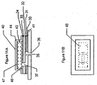
- FIG. 1 there is shown a top perspective view of one embodiment of the multi-functional filter assembly 40 of the present invention as it would appear looking down on the filter mounted to an interior wall of a drive enclosure housing 41.
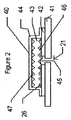
- Figure 2 shows a side cross-sectional view of another embodiment of a filter assembly 40 of the present invention as it would appear mounted on a disk drive enclosure housing 41.
- the air stream path is indicated as 21.
- the adhesive layer 42 mounts the filter 40 to the housing 41 and has a hole or opening 45 to allow the air stream through the adhesive layer.
- Layer 44 is the filter media.
- Layer 43 is the adsorbent, In this embodiment, the adsorbent 43 is a single layer adsorbent with grooves on the top surface 47 and bottom surface 46.
- bottom of the adsorbent is the side closest to or facing the opening.
- the top is opposite the bottom.
- a second optional filter media layer 26 is located such that the filter media encapsulates the adsorbent 43.
- Such a construction is desirable for adsorbents which may particulate because the filter media prevents such particulation from entering the drive during installation. Moreover, if the filter media is hydrophobic, the filter is washable.
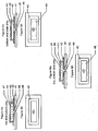
- Figure 3 shows additional features of a computer hard disk drive into which the filter assembly of Figure 1 has been incorporated. Additional components typically present within a drive are shown, such as the rotating magnetic recording disks 11, the read/write heads 12 and the armatures 13 for moving the heads.
- the rotating disks 11 are the driving force for circulating, or recirculating, air within the disk drive.
- Figures 4A and 4B show a side cross-sectional and top view respectively of one embodiment of the filter assembly 40 having the grooves on multiple surfaces, here shown as having grooves on the top and bottom surfaces.
- the filter 40 comprises a layer of adhesive 42 with hole 45 cut through it.
- an adsorbent layer 43 superimposed on the adhesive layer 42 is an adsorbent layer 43, with grooves on top 47 and bottom 46 surfaces.
- a filtration layer 44 covers the adsorbent layer and is adhered to the adhesive layer 42.
- the adhesive may comprise a pressure sensitive adhesive layer, a double-sided adhesive tape on a backer material or multiple sided adhesive on multiple backers, depending on the desired construction of the filter.
- the adhesive may also comprise a heat sensitive or UV or other curable adhesive layer.
- the hole 45 is aligned with a hole in the enclosure, such that air will enter the drive housing through the enclosure hole and the hole 45 in the adhesive layer 42. The air will then pass along the bottom grooves in the adsorbent layer and either pass through the filter layer 44 or along the sides of the adsorbent media and then further along the grooves in the top of the adsorbent media before passing through the filter media 44.
- Figures 5A and 5B show side cross-sectional and top view respectively, of another embodiment of the filter assembly 40 not covered in this invention where there are grooves on the bottom 46 and side 48 surfaces.
- the layers are similar to those shown in Figures 4A and 4B .
- Figures 6A and 6B show a side cross-sectional and top views respectively of another embodiment with grooves on the top 47, bottom 46, and side 48 surfaces. Again the layers are defined similarly to the way they were defined for Figures 4A and 4B respectively.
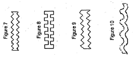
- Figures 7, 8, 9, and 10 show a few of the possible groove patterns for the adsorbent layer when grooves are used on the top and bottom surfaces. These by no means exhaust the possibilities, but are shown for illustrative purposes.
- the grooves in the adsorbent form peaks and valleys.
- Figure 7 shows a point-aligned pattern in the grooves.
- Figure 8 shows a square aligned pattern in the grooves.
- Figure 9 shows a point unaligned pattern in the grooves and Figure 10 shows a wavy unaligned pattern in the grooves. Additional patterns are easily envisioned and mixtures of patterns such as aligned top point and bottom square patterns can be used.
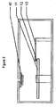
- FIG 11A and 11B show a side cross-sectional view and a top view respectively of another embodiment of the present invention where a diffusion tube is included with the adsorbent breather filter 40.
- Layers 30, 31, and 32 are a double-sided adhesive where layers 30 and 32 are adhesive coated onto the carrier layer 31.
- the adhesive and carrier layers 30, 31, and 32 have a hole or slot 35 cut through them that will be aligned at one end with a hole 36 in the disk drive enclosure wall 41.
- Layers 33 and 34 form a single sided adhesive layer, with layer 34 being the adhesive on a carrier layer 33.
- Adsorbent layer 43 is an adsorbent layer in this case with grooves on top 47 and bottom 46 and side 48 superimposed over hole 37 and extending further over part of layer 34.
- Layer 44 is a filter layer, such as of a high efficiency membrane for good breather filtration efficiency, which covers adsorbent layer 43 and is adhered to adhesive layer 34
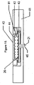
- FIG 12 is a side cross-sectional view of another embodiment of the present invention that is an outside mount version of the invention.
- filter 40 mounts on the outside of the enclosure wall 41 instead of the inside as previously shown.
- Layer 51 is an adhesive layer that may be only adhesive or a double sided adhesive layer as previously detailed that has hole 56 cut through it and is placed over the vent hole 45 of the enclosure wall 41.
- Filter layer 53 is against the adhesive layer 51 and may be laminated or adhered to the adsorbent layer 43 and filters incoming air of particulates and retains the carbon particles from entering the drive.
- Adsorbent layer 43 is shown with grooves on top 46 and on bottom 47.
- Layer 52 is an air impermeable layer that protects the carbon from the environment and retains the carbon.
- Filter 40 removes contaminates from the air within the drive via access through openings 56 and 45 and from the air passing through hole 55 in the impermeable layer 52 and further through the filter into the drive interior.
- the hole 55 may be offset from holes 45 and 56, but need not be.
- the outside mount filter is shown here as mounting on a flush enclosure wall 41, but the enclosure wall 41 could also be recessed and the filter mounted such that when installed, the filter outside surface may be flush with the outside wall surface. In such cases it may be possible to have the impermeable layer 52 optionally mounted on the outer wall surface instead of the filter itself.
- filter layers may be inserted such as between the adsorbent layer 43 and the impermeable layer 52 if desired by use of lamination of layers together or by using additional adhesive or adhesive layers.
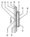
- Figures 13A and 13B are side cross-sectional and top views respectively of an additional embodiment of the present invention where the filter is mounted on the outside of the enclosure wall similar to the Figure 12 embodiment, but also has built in diffusion tube characteristics similar to the Figures 11A and 11B embodiment
- Filter 70 is applied to the outside of enclosure surface 41.
- Adhesive layer 42 again can be a layer of adhesive or a double sided adhesive layer with hole 56 cut in it and applied such that hole 56 aligns with hole 45 in the enclosure wall 41.
- Filter layer 53 is against the adhesive layer 42 to filter the incoming air of particulates and retains the carbon particles of the adsorbent layer 43, which in this illustration has top, bottom, and side grooves.
- Layer 58 is an impermeable layer over the adsorbent layer 43.
- adhesive layer 51 could have optionally have adhesive on either side for aiding assembly of the filter.
- adhesive layer 51 could have optionally been a single sided adhesive.
- Hole 64 is cut through the layer 58 to allow airflow to pass from the exterior to the carbon and eventually into the enclosure.
- Layers 59, 60, and 61 are a double-sided adhesive with layers 59 and 61 being adhesive on both sides of the carrier 60.
- Hole or slotted hole 62 is cut through layers 59,60, and 61 and aligns one end with hole 64 through the impermeable layer 58. Impermeable layer 57 then is placed on layer 61.
- layer 61 could be an adhesive layer on the impermeable layer 57 and layers 59 and 60 could have been a single sided adhesive, again showing flexibility of construction possibilities.
- Hole 63 is cut in impermeable layer 57 and aligns with hole or slot 62 aligning at the opposite end of the hole or slot as hole 64 aligned.
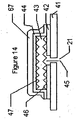
- FIG 14 is a side cross-sectional view of an alternative embodiment of the present invention with a recirculation filter included as part of the construction.
- the construction of this illustration is the same as was used in Figure 2 except that another filter layer 67 is placed over filter layer 44.
- Filter layer 67 is typically a more open layer to allow more airflow through the layer to have increased performance to clean air passing through it of particles.
- air is recirculated around inside the drive and such open filtration layers are typically used as a recirculation filter to clean the inside of the enclosure of particles.
- layers 44 and 67 could be combined into a single layer that is both open enough to allow recirculating air to flow through it to clean it of particles and efficient enough to clean the incoming air sufficiently of particles.
- One possible media of construction for layer 67 is an electret material.
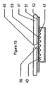
- Figure 15 is a side cross-sectional view of another embodiment of the present invention which is similar to that shown in Figure 2 , where now a filler or gasket 81 is placed over the filter that is countersunk into the enclosure wall such that the resultant filter and gasket are flush mounted into the enclosures.
- This can be of value to minimize the filter's disturbance to airflow and to minimize the space the filter takes up inside the enclosure. Both these can be important particularly for high revolution per minute disk drives and for very small disk drives.
- Figures 16A and 16B are cross-sectional and top views respectively of another embodiment of the invention similar to Figures 4A and 4B , except where the adsorbent layer 43 has a perimeter top groove 77.
- Figures 17A and 17B are cross-sectional and top views respectively of a further embodiment of the invention again similar to Figures 4A and 4B where the adsorbent layer 43 is replaced by multiple adsorbent layers, in this case layers 82 and 83.
- impermeable layer shown in Figures 12 and 13 .
- Polymer layers such as polyester, polypropylene or the like can be used as well as metallized polymer layers such as a metallized polyester.
- a preferred impermeable layer is a layer of thin aluminum. More preferably the impermeable layer is dead soft aluminum because it is impermeable, formable, and provides a good electromagnetic shield. For example, a 0.003" (76 ⁇ m) thick dead soft aluminum layer as sold by ALL FOILS Brooklyn Heights, Ohio, is appropriate for use in the invention.
- Airflow was tested by making a fixture where the filter of the invention could be adhered over a hole in the fixture.
- the size of the hole in the fixture was 0.08" (0.203cm) in diameter. Air was delivered to the back side of the filter through a port (to allow air to flow through the hole in the mounting adhesive and through the filter). Another port on the fixture was placed to measure back pressure or the pressure required to flow a given volume of air through the filter.
- the filters were all tested at an airflow rate of 30 ml/min. Various filter constructions could then be tested and compared for airflow.
- Adsorption rate was measured by placing an equal number of samples of comparative parts in identical jars suspended over an identical amount of an organic compound. For the test one sample was suspended over 50ml of TMP (trimethylpentane) in 500 ml jars and weighed every fifteen minutes for two hours. The weight gain was recorded and the weight gain per unit time was graphed and calculated.
- TMP trimethylpentane
- Samples were made to test for resistance to airflow. Each sample was made using a commercially available double sided acrylic adhesive from Adhesive's Research in Glenn Rock, PA.
- the adsorbents were all filled PTFE having 240 mg of activated carbon and made in accordance to US patent 4,985,296 .
- the adsorbent layers were further compressed to form 15 mil (381 ⁇ m) grooves as described in the detailed description section of this patent.
- the filter layers were 0,2 ⁇ m rated PTFE membranes as made and supplied in finished filters by W. L. Gore and Associates, Newark DE. The filters were placed on the airflow test fixture as described above and tested.
- Samples were made to test adsorption rate performance. Each sample was made using a commercially available double sided acrylic adhesive from Adhesives Research in Glenn Rock, PA.
- the adsorbents were all filled PTFE having 240 mg of activated carbon and made in accordance to US patent 4,895,296 .
- the adsorbent layers were further compressed to form 15 mil (0.38mm) deep grooves as described in the detailed description section of this patent
- the filter layers were 0.2 micron rated PTFE membranes as made and supplied in finished filter form by W. L. Gore and Associates in Newark, DE.
Landscapes
- Chemical & Material Sciences (AREA)
- Chemical Kinetics & Catalysis (AREA)
- Engineering & Computer Science (AREA)
- Analytical Chemistry (AREA)
- General Chemical & Material Sciences (AREA)
- Oil, Petroleum & Natural Gas (AREA)
- Filtering Materials (AREA)
- Separation Of Gases By Adsorption (AREA)
- Solid-Sorbent Or Filter-Aiding Compositions (AREA)
- Separation Using Semi-Permeable Membranes (AREA)
Description
- This invention relates to a device for filtering contaminants, such as particulates and vapor phase contaminants, from a confined environment such as electronic or optical devices susceptible to contamination (e.g. computer disk drives). Specifically, the filter assembly filters contaminates that are generated from within the device and optionally from inlet air into the device.
- Many enclosures, that contain sensitive equipment must maintain very clean environments in order for the equipment to operate properly. Examples include enclosures for the following: optical surfaces or electronic connections that are sensitive to particulates and gaseous contaminants which can interfere with mechanical, optical, or electrical operation; data recording devices, such as computer hard disk drives that are sensitive to particles, organic vapors, moisture and corrosive vapors; processing of thin films and semiconductor wafers; and electronic controls such as those used in automobiles and industrial applications that can be sensitive to particles, moisture buildup and corrosion as well as contamination from fluids and vapors. Contamination in such enclosures originates from both inside and outside the enclosures. For example, in computer hard drives, damage may result from external contaminates as well as from particles and vapors generated from internal sources. The terms "hard drives" or "hard disk drives" or "disk drives" or "drives" will be used herein for convenience and are understood to include any enclosure for equipment or material that is sensitive to contamination.
- Disk drives must be protected against a large number of contaminants that are found in the surrounding environment and can penetrate the drive. This is particularly true for drives that are removable and portable to any environment such as disk drives that are used in laptop computers or in Personal Computer Memory Card International Association (PCMCIA) slots, or other drives which may not be used in the typical data processing environment. Drives used in applications such as gaming systems, personal video recorders, automotive mapping systems and others must survive in environments that are more severe than that of standard desk top computer applications.
- Contamination may occur in various forms. For example, disk drives are susceptible to corrosive ions, such as chlorine and sulfur dioxides, and may also be sensitive to variations in humidity. Accordingly, an array of failure mechanisms exist. One serious contamination-related failure mechanism in computer disk drives is static friction or "stiction." Stiction results from the increased adhesion of a drive head to a disk while the disk is stationary plus increased viscous drag parallel to the head-disk interface. Newer high density disks are more sensitive to contamination-caused stiction because they are smoother and include relatively thin layers of lubricants. Contaminants on the disk change the surface energy and increase the adhesive forces between the head and disk, causing stiction. Also, stiction may be caused by vapors condensing in the gap between the head and disk. The low energy low torque motors that are being used in smaller disk drives for portable computers and the low noise drives used in other applications, such as personal video recorders, are increasingly sensitive to stiction related failures.
- Another serious contamination-related failure mechanism is a head crash. Head crashes can occur when particles get into the head-disk interface. The spacing or flying heights between the head and disk during operation of modern high density drives is 30 nanometers or less. As rotational speed affects the maximum data transfer rate a drive can have, rotational speed of modern disk drives is increasing. Some current drives operate at 15,000 revolutions per minute and future drives will likely use even higher speeds. With such high speeds and low flying heights, even submicron-sized particles can be a problem, causing the head to crash into the particle or the disk after flying over a particle, bringing the drive to an abrupt failure mode. Particles can also adversely affect data integrity and mechanical reliability of a drive, sometimes referred to as thermal asperity.
- Disk Drives are also susceptible to variances in humidity. Low humidity is problematic either because it may increase static electricity or decrease lube thickness or functionality. However, in high humidity, corrosion is promoted and lubricants may swell. It takes significantly more adsorbent to protect a drive from humidity than it does from organic or acid gas contamination. Thus drives that need buffering from humidity fluctuations require significant amounts of adsorbent.
- To prevent contamination-related failure, a variety of filtration devices have been used. For example, filtration devices to keep particles from entering disk drives are well known. Some consist of a filtration media held in place by a housing of polycarbonate, acrylonitrile butadiene styrene (ABS), or some other material. Others consist of a filtration media in the form of a self-adhesive disk utilizing a layer or layers of pressure sensitive adhesive, Such filters are mounted and sealed over a vent hole in the enclosure to filter particulates from the air entering the drive. Filtration performance depends not only on the filter media having a high filtration efficiency but also on having it have a low resistance to airflow or pressure drop. If the pressure drop is too high, unfiltered air will leak into the enclosure through a gasket, screw hole, or other seam instead of entering through the filter. Such filters may work well for particulates of external origin, but do not address the problems from vapor phase contaminants.
- Internal particulate filters, or recirculation filters, are also well known. These filters are typically pieces of filter media, such as expanded PTFE membrane laminated to a polyester nonwoven backing material. Other recirculation filters are "pillow-shaped" filters containing electret (i.e., electrostatic) filter media. These filters may be pressure fit into slots or "C" channels and are placed in an active air stream such as near the rotating disks in a computer hard disk drive or in front of a fan in electronic control cabinets, etc. Alternatively, the recirculation filter media can be framed in a plastic frame. Recirculation filters work well for particulate removal of internally generated particles but do not address the problem of vapor phase contaminants, nor do they provide protection from external particles entering the drive.
- Internal adsorbent filters are also well known. One example is described in
U.S. Patent 4,830,643 issued to Sassa et al. This patent teaches a sorbent filter where a powdered, granular or beaded sorbent or sorbent mixture is encapsulated in an outer expanded PTFE tube. This filter is manufactured by W.L. Gore & Associates, Inc., Elkton, Maryland, and is commercially available under the trademark GORE-SORBER® module. A second well known internal adsorbent assembly is described inU.S. Patent 5,593,482 issued to Dauber et al. A third internal adsorbent assembly incorporates a layer of adsorbent such as activated carbon/PTFE composite between two layers of filter media or is alternately wrapped in a layer of filter media and can be installed between slots or "C" channels much the way a recirculation filter is installed but without significant airflow through the filter. Such a filter is described inU.S. Patent 5,500,038 issued to Dauber et al. - Known internal adsorbent filters work well at adsorbing vapor phase contaminants, but they do not filter particulates very well. They may collect particles by some impaction of particles onto the filter (i.e., by having the larger particles impacting or colliding with the adsorbent filter as particle-laden air speeds around the filters) or by diffusion of particles onto the filter. However, these filters do not perform nearly as well as the standard recirculation filters, which work by a combination of sieving (mechanically capturing particles too large to pass through the pore structure of the filter), impaction (capturing particles too large to follow the bending air streams around filters or the fibers of the filter), interception (capturing particles that tend to follow the air streams, but are large enough to still intercept a filter fiber or in other words those particles with a diameter equal to or less than the distance between the fiber and the air stream line), and diffusion (capturing smaller particles buffeted about by air molecules in a random pattern and coming into contact with a filter fiber to become collected).
- Because there is a need to remove vapor phase contaminates as well as particles from both internal and external sources, combination sorbent breather filters were developed. These can be made by filling a cartridge of polycarbonate, ABS, or similar material with sorbent and securing filter media on one or both ends of the cartridge and placing the cartridge over a hole in the container wall. These filters effectively cleanse incoming air of particles and vaporous contaminates, and internal air of internally generated vaporous contaminates. Because the filters are inside, the drive contaminate will diffuse into the adsorbent sections of the filters. Examples of such filters are described in
U.S. Patents 4,863,499 issued to Osendorf (an anti-diffusion chemical breather assembly for disk drives with filter media having a layer impregnated with activated charcoal granules); 5,030,260 issued to Beck et al. (a disk drive breather filter including an assembly with an extended diffusion path; 5,124,856 issued to Brown et al. (a unitary filter medium with impregnated activated carbon filters to protect against organic and corrosive pollutants); and 5,447,695 issued to Brown et al. (Chemical Breather Filter Assembly). Unfortunately, many of these designs are too large and take up too much space in today's miniaturized drives. - A second combination adsorbent breather filter is also well known that encapsulates the adsorbent material such as an impregnated activated carbon polytetrafluoroethylene (PTFE) composite layer between two layers of filter media and is applied over a hole in the enclosure with a layer or layers of pressure sensitive adhesive. These filters work well to an extent and are of a size that can be used in today's small drives and are typically designed to filter air coming into the drive. Thus, the adsorbent is typically primarily designed to adsorb both organic and corrosive vapors from the outside environment and will filter particulates only from air coming into or leaving the drive. Internally generated vapors and moisture can be adsorbed by these filters, but often times they have been used in conjunction with another larger internal adsorbent filter so the adsorbent breather filter can be smaller in size. Therefore, such filters may not contain enough adsorbent to adequately adsorb all the internally generated contaminants and typically will not contain enough adsorbent to control humidity well within the drive as previously mentioned. Again, particles, are also generated inside the drive and are not typically captured by these filters.
- Another well known combination filter is an adsorbent recirculation filter that adds an adsorbent layer inside the before mentioned recirculation filter. These can filter particles and vapors once inside the drive but do not limit particles and vapors from coming into the drive. As such it allows the incoming contaminants an ability to contact a drive head or disk before being collected by the filter.
- Additionally, to adsorb corrosive compounds such as chlorine and sulfur dioxide, an adsorbent is typically treated with a salt to chemisorb the contaminants. However, when known filters are washed in deionized water, large amounts of these salts may be released, which makes them unacceptable in sensitive disk drive environments.
- A washable adsorbent recirculation filter is described in
U.S. Patent 5,538,545 issued to Dauber et al. , wherein expanded PTFE membranes or other hydrophobic materials are used to encapsulate the adsorbent. However, these filters do not filter air as it comes into the drive before it has had a chance to deposit particles and do damage to the drive. - Combinations of several filters having different functions in a single drive have been taught. For example,
U. S. Patent No. 5,406,431, to Beecroft , describes a filter system for a disk drive that includes an adsorbent breather and recirculation filter in specifically identified locations within the drive. Also, U. S. Patent No.4,633,349, by Beck et al. , teaches a disk drive filter assembly comprising a dual media drum type filter element in a recirculating filter assembly that surrounds a breather filter. Further,U. S. Patent No 4,857,087 to Bolton et al. , teaches incorporating a breather filter in a recirculation filter housing, but has significantly more parts and incorporates a third filter element complete with housings, apertures, and gaskets to accomplish this inclusion. The combinations described in these patents either locate the filter components in separate regions of the disk drive or incorporate space-consuming fixtures to orient the component parts within the drives. - Space saving combinations having further multifunctionality have also been taught. These include
U. S. Patent No 6,266,208 to Voights integrating a recirculation filter, breather filter, and adsorbent filter into a single unitary filter;U.S. Patent No 6,238,467 to Azarian et al incorporating a breather filter, adsorbent filter, and recirculation filter into a rigid assembly filter;U.S. Patent 6,296,691 to Gidumal incorporating a breather filter adsorbent filter and recirculation filter into a molded filter; and U. S Patent No6,395,073 to Dauber incorporating the recirculation filter and breather filter with optional adsorbent filter into a low profile adhesive construction. All but the last filter design by Dauber are filters of considerable size and are not appropriate for smaller drives like the 2.5" laptop drives and smaller 1.8" drives, 1.0" drives and 0.85" drives that are currently in the market and/or in design. - As disk drives have become smaller and less expensive, there is a need for simplification and the reduction in the number of parts in a drive to reduce cost and improve performance. However, as the drives increase in recording data density and capacity, they become more sensitive to particulate and vaporous contamination including increased sensitivity to moisture.
- Existing filtration means often do not meet these demanding filtration requirements. The low profile adsorbent breather filters and low profile multifunction filters best suited in size to fit these smaller drives have had to compromise in adsorbent content because they needed airflow through the filter. The compromise has been to either use very dense adsorbent media and have limited airflow, or use less dense adsorbent media to maintain airflow but then have limited adsorbent capacity. Two recent inventions have tried to overcome this deficiency.
U.S. Patent No 6,683,746 to Kuroka et.al. allows for air bypass of the adsorbent media to increase airflow, but can have performance reductions in adsorption if too much air by-passes the adsorbent media.U.S. Patent No 6,712,887 to Ueki et.al. uses grooves in the adsorbent media to increase airflow, but this has limited functionality as there are further limitations to airflow through the filtration layer unaddressed. - In one aspect, the invention is an adsorbent assembly for removing contaminants within an enclosure comprising an adhesive; an adsorbent media having a bottom surface, a top surface, and at least one side surface; and a filter media covering the adsorbent media, wherein the filter media is adjacent to the top surface and the at least one side surface of said adsorbent media and said adsorbent media includes at least one groove adjacent to the filter media, and wherein the at least one groove is on the top surface of said adsorbent media. In this aspect the at least one groove is preferably at least about 1 mil (0.025mm) deep, more preferably at least about 5 mil (0.127mm) deep, most preferably at least about 10 mils (0.254mm) deep.
- In another aspect, the present disclosure relates to an adsorbent breather assembly for removing contaminants within an enclosure having a fluid inlet/outlet port comprising: an adhesive; an adsorbent media having a bottom surface, a top surface, and at least one side surface, the adsorbent media in fluid communication with the port; and a filter media covering the adsorbent, wherein the filter media is adjacent to the top surface and at least one side surface of the adsorbent media and the adsorbent media includes at least one groove adjacent to the filter media. In this aspect, the at least one groove is preferably at least about 1 mil (0.025mm) deep, more preferably at least about 5 mils (0.127mm) deep, most preferably at least about 10 mils (0.254mm) deep.
- In still another aspect, the present disclosure provides an adsorbent assembly having a bottom surface adjacent to a layer of adhesive.
- In yet another aspect, the present disclosure provides a filter media comprising a porous polymeric membrane. In this aspect the porous polymeric membrane is preferably hydrophobic, more preferably, the porous polymeric membrane comprises PTFE membrane.
- In another aspect, the present disclosure provides a filter that includes an electret particle filtering layer disposed on the porous polymeric membrane.
- In another aspect the present disclosure provides a filter media comprising an electret filter media.
- In still another aspect, the present disclosure provides an adsorbent media comprising PTFE and an adsorbent material. In this aspect, the adsorbent media comprises a PTFE membrane filled with an adsorbent material.
- In yet another aspect, the present disclosure provides a molded adsorbent media.
- In a further aspect, the present disclosure provides an adsorbent media which is a non- woven fabric impregnated with an adsorbent.
- In another aspect, the present disclosure provides an adsorbent media which is a granular material disposed on at least one side of a fiber scrim.
- In still another aspect, the present disclosure provides an adsorbent media comprising a physisorbent. In this aspect, the physisorbent is selected from the group consisting of activated carbon; activated alumina; molecular sieves; silica gel and combinations thereof.
- In yet another aspect, the present disclosure provides an adsorbent media comprises a chemisorbent. In this aspect, the chemisorbent is a material impregnated with at least one material selected from the group consisting of potassium permanganate, calcium carbonate, potassium carbonate, potassium hydroxide, sodium carbonate and calcium sulfate; and combinations thereof.
- In a further aspect, the present disclosure provides an adsorbent media having a bottom surface, a top surface and at least one side surface wherein the adsorbent media includes at least one groove on a side surfaceor the bottom surface of the adsorbent media.
- In another aspect, the present disclosure provides an adsorbent media or breather filter including two or more grooves on any one surface. In this aspect, the grooves may be parallel, form a radial pattern or intersect.
- In still another aspect, the present disclosure provides an adsorbent assembly or breather filter, wherein the adsorbent media comprises two or more layers.
- In yet another aspect, the present disclosure provides an adsorbent assembly or breather filter, in which the adsorbent media includes a first layer having at least one groove and a second layer adjacent to the first layer, the first and second layers positioned such that the at least one groove of the first layer is adjacent to the second layer. In this aspect, the second layer may include at least one groove and the first and second layers may be positioned such that the at least one groove of the first layer faces the at least one groove of the second layer.
- In a further aspect, the present disclosure provides an adsorbent assembly or breather filter having an adsorbent comprising a first and second layer, in which the first and second layers include grooves forming peaks and valleys and the first and second layers are positioned such that the valleys of the first layer overlap the peaks of the second layer.
- In yet another aspect, the present invention provides a method of removing contaminants from an enclosure comprising the steps of: providing an enclosure defining a sealed volume and having a fluid inlet port; providing an adsorbent assembly comprising: an adhesive, an adsorbent media having a bottom surface adjacent to the enclosure, a top surface opposite the bottom surface and at least one side surface, the adsorbent media in fluid communication with the fluid inlet port and the sealed volume; and covering at least the top surface and a side surface of the adsorbent media with a filter media, wherein the adsorbent media includes at least one groove adjacent to the filter media, and wherein the at least one groove is on the top surface of said adsorbent media.
- The operation of the present invention should become apparent from the following description when considered in conjunction with the following drawings, in which:
-
Figure 1 is a top view of an embodiment of the filter unit of the present invention as it would be located on a drive housing; -
Figure 2 is a side cross-sectional view of an embodiment of the filter unit of the present invention as it would appear on the enclosure housing; -
Figure 3 is a side cross-sectional view of a computer hard disk drive showing an embodiment of the filter unit of the present invention installed therein; -
Figures 4A, 4B are side cross-sectional and top views, respectively, of an embodiment of the filter unit of the present invention having grooves on the top and bottom surfaces of the adsorbent layer; -
Figures 5A and 5B are side cross-sectional and top views, respectively, of another embodiment of the filter unit not according to the present invention having grooves on the side and bottom sides of the adsorbent layer; -
Figures 6A and 6B are side cross-sectional and top views, respectively of another embodiment of the filter unit of the present invention having grooves on the top, bottom, and sides of the adsorbent layer; -
Figure 7 is a side cross-sectional view of a top and bottom point aligned groove pattern embodiment of the adsorbent layer of the present invention; -
Figure 8 is a side cross-sectional view of a top and bottom square aligned groove pattern embodiment of the adsorbent layer of the present invention. -
Figure 9 is a side cross-sectional view of a top and bottom point unaligned groove pattern embodiment of the adsorbent layer of the present invention -
Figure 10 is a side cross-sectional view of a top and bottom wavy unaligned groove pattern embodiment of the adsorbents layer of the present invention; -
Figures 11A and 11B are side cross-sectional and top views respectively of another embodiment of the present invention including a diffusion tube within the construction of the filter element. -
Figure 12 is a side cross-sectional view of another embodiment of the present invention showing the filter element in an outside mount configuration. -
Figures 13 and 13B are side cross-sectional and top views respectively of another embodiment of the present invention showing the filter in an outside mount configuration with a diffusion tube within the construction of the filter element; -
Figure 14 is a side cross-sectional view of another embodiment including a recirculation filter included within the filter construction; -
Figure 15 is a side cross sectional view of another embodiment with a filler or gasket around the filter that is countersunk into the drive baseplate such that the assembled filter and gasket are level with the drive baseplate. -
Figure 16 is a side cross-sectional and top view of another embodiment not according to the present invention where a top perimeter groove is used along with bottom grooves. -
Figure 17 is a side cross-sectional view of another embodiment in which the adsorbent comprises multiple layers of adsorbent material with grooves of the two layers facing each other. -
Figure 18 is a cross sectional view of another embodiment not according to the present invention in which the adsorbent assembly has a grooved bottom surface without airflow through the filter. -
Figure 19 is a cross sectional view of an outside mounted adsorbent assembly with a grooved bottom surface, which is not according to the present invention. - The adsorbent assembly filters and adsorbent breather filters of the present invention include a grooved adsorbent layer, an adhesive, and a filter layer covering the adsorbent. As used herein, an adsorbent assembly filter is a filter adapted to remove contaminants from an enclosure. As used herein, an adsorbent breather filter is an adsorbent filter adapted to be used in an enclosure having an opening or port, such that the filter removes at least some contaminants from the air coming into the filter. Grooves on the surfaces of the adsorbent improve filter performance. The filter layer is adjacent to the top and at least one side of the grooved adsorbent. Preferably, the adhesive includes an adhesive layer for attaching the filter to the drive.
- The present invention consolidates filtration functions which were often performed by two, three, or more filters into a single filter that functions well, is easy to install, is clean and cleanable. Moreover, as one of skill in the art will readily appreciate, further components, such as a gasket or gasket(s) or vibration dampening materials, can be included to further reduce the number of components required for final assembly. Common to all embodiments of the invention is the highly dense adsorbent media grooved on at least one surface and often times on multiple surfaces to allow good air access and airflow while maintaining maximum adsorbent capacity and good adsorbent performance.
- The filter may comprise a layer or layers of adhesive to attach the filter to the proper location on the interior or exterior of the drive enclosure wall. The filter may optionally cover an inlet diffusion tube or channel in the drive housing, or the filter may fully contain a diffusion tube. A layer of filter media to filter the incoming air of particles is provided in substantially laminar relation to the adhesive. An optional layer or layers of filter media can be provided to filter recirculating air. A layer or layers of adsorbent media with grooves on multiple surfaces is provided between the adhesive and filter layers, or between filter media layers, to filter one or both of the incoming and recirculating air streams of vaporous contaminants. Appropriate partitioning of the filter is provided to permit flow channels for inlet air and for recirculating air without the possibility of allowing unfiltered inlet air through the filter.
- The adsorbent may comprise one or more layers of 100% adsorbent materials, such as granular activated carbon, or may be a filled product matrix such as a scaffold of porous polymeric material compounded with adsorbents that fill the void spaces. Other possibilities include adsorbent impregnated nonwovens or adsorbent beads on a scrim where the non-woven or scrim may be cellulose or polymeric and may include latex or other binders as well as porous castings or tablets of adsorbents and fillers that are polymeric or ceramic. The adsorbent can also be a mixture of different types of adsorbents, fillers, and binders.
- Suitable adsorbents include: physisorbers (e.g. silica gel, activated carbon, activated alumina, molecular sieves, etc.); chemisorbers (e.g. potassium permanganate, potassium carbonate, potassium hydroxide, potassium iodide, calcium carbonate, calcium sulfate, sodium carbonate, sodium hydroxide, calcium hydroxide, powdered metals or other reactants for scavenging gas phase contaminants); as well as mixtures of these materials. For some applications, it may be desirable to employ multiple layers of adsorbent materials, with each layer containing different adsorbents to selectively remove different contaminants as they pass through the filter or as they may be exposed from inside the enclosure.
- Preferably the adsorbent utilizes an adsorbent-filled PTFE sheet wherein adsorbent is entrapped within the reticular PTFE structure as taught by
U.S. Patent No. 4,985,296 issued to Mortimer, Jr. Most preferably, particles are packed in a multi-modal (e.g. bi-modal or tri-modal) manner with particles of different sizes interspersed around one another to fill as much of the available void space between particles as is possible, so as to maximize the amount of active material contained in the core. This technique also allows a number of sorbents to be filled into a single layer. The core can then be Compressed or layered and compressed to maximize adsorbent loading and density. Previously air flow was required through the adsorbent and expanding of the material was required to allow for airflow, but with this invention the material can be compressed and grooved on multiple surfaces to allow for good airflow, good adsorbent performance and maximum adsorbent loading and density. - Another preferred embodiment of the adsorbent layer that can be used in the present invention is discussed in detail in Japanese Patent Publication Number
JPH04323007 (A - In one aspect, the adsorbent includes grooves forming depression or valleys in the surface of the adsorbent. The valleys contrast with the peaks, which project from the surface of the adsorbent. As used herein, a peak or valley may be of any shape resulting from the grooving of the adsorbent. For example, grooves may be square, elliptical, triangular or any other shape without departing from the invention. Groove size and pattern may also be varied according to the application. Groove patterns may include, without limitation; parallel, radial and crossing or intersecting patterns.
- In one aspect, the adsorbent may comprise multiple layers. The layers may include one or more layers including grooves. The grooved layers may be positioned so that the grooved surfaces of one layer are adjacent, or opposite the grooved surface of another layer. Alignment of grooves in adjacent layers can be random, aligned or unaligned. Groove size may vary between adsorbent layers. For example, the adsorbent may comprise two layers, each layer including square grooves. The square grooves may be aligned, such that the peaks of the first adsorbent layer align with the valleys of the second adsorbent layer.
- In the embodiments described and illustrated herein, the adhesive is typically a mounting adhesive layer mounting the filter to the enclosure wall. However, the adhesive layer may have different constructions. It can be either a single layer of transferable adhesive, a single sided adhesive coated onto a carrier or substrate such as polyester or polyethylene, or a double-sided adhesive coated onto a carrier or substrate as described within the illustrations. A preferred adhesive utilizes a high peel strength of greater than 30 ounces/inch (328 N/m) as measured by PSTC#1 (Pressure Sensitive Tape Council), low outgassing of less than 0.1% collected volatile condensable material (CVCM) as measured by ASTM-E595-84, solvent-free non-particulating permanent acrylic pressure sensitive adhesive. A double-sided adhesive tape may also be preferred for certain constructions because it is easier to handle, and the substrate adds support and rigidity to the filter construction. A commercially available adhesive satisfying these requirements is 3M 444 adhesive, available from Minnesota Mining & Manufacturing in Minneapolis, MN. Other adhesives, such as hot melt adhesives, UV curable adhesives, thermosets, thermoplastics, or other curable or activatable adhesives etc. are also suitable. Furthermore, if a diffusion tube is desired, adhesives as described in
U.S Patent 5,417,743 can be used. In many of the applications described herein that incorporate a diffusion tube, a second adhesive layer is superimposed over the first. This second layer could again be just adhesive, but a single-sided (i.e., adhesive on one side of a carrier or substrate) or double-sided adhesive is preferred for ease in handling and processing. - Prior to attachment to the disk drive housing, the exposed adhesive layers may have one or more release liners adhered thereto to protect the adhesive and to facilitate handling of the filters. The release liners would typically be removed prior to assembly of the filter onto the disk drive enclosure.
- PTFE membrane filter materials can be used to cover the adsorbent material and act as filtration membranes. One such preferred filter media to encapsulate the adsorbent layer is a layer of expanded PTFE membrane made in accordance to
U.S. Patent No. 4,902,423 issued to Bacino et al. This filter media may be structurally supported by a layer of woven, nonwoven, or expanded porous material, such as polyester, polypropylene, polyamide, etc. This filter media has several advantages. It can be made very highly permeable, with resistances to air flow of less than 0.5 mm H2O @ 105 feet per minute (3.2 meters per minute) and still contain adsorbent particulate within the filter. - The particle filtration efficiency of this highly expanded membrane as measured on a TSI 8160 efficiency test rig available from TSI Inc., in Minnesota, is also very good (e.g. in excess of 55% at 0.3 µm) which provides good particle filtration along with the adsorbent containment. A preferred support layer is a Reemay 2014 polyester nonwoven, 1.0 oz/yd2 (34 g/m2) available from Reemay, Inc., Old Hickory, Tennessee.
- A second preferred filter media to cover or encapsulate the adsorbent layer, and more preferably to be used in the embodiments with a recirculation filter is a layer of an electrostatic triboelectret material available in finished filter form from W. L.. Gore and Associates, Inc. under the trademark GORETRET® recirculation filters. An illustrated example of this would be
layer 67 inFigure 14 . Advantages of this media are that it is very high in efficiency (e.g., in excess of 90% @ 0.3 µm) and also very permeable (e.g., less than 1 mm H2O at 10.5 fpm or 3.2 m/min). While this media loses its charge while being washed with deionized water, it immediately regains its efficiency upon drying due to the triboelectric effect of the mix of dissimilar fibers. - Other filter materials can also be used. They could be other electrets or other triboelectret materials that yield high efficiencies and low resistances to airflow. They could also be other filter papers or filter membranes such as polypropylene membranes or cast polymeric membranes or some combination of filter materials. Different filter materials with different properties can be used in the different embodiments of the invention wherever filter layers are used and/or optionally used depending upon the required performance needed.
- An outer protective layer can also be used to add durability to the filter and to contain any protruding fibers from either the triboelectret type filter media or the filter support media for the membrane filter media. Typically, this would be an extruded or expanded plastic material such as polypropylene, polyethylene, polyamide, polyester, etc. A preferred material is a Delnet 0707 expanded polypropylene material available from DelStar Technology, Inc., Middletown, DE.
- Using PTFE membranes as a filter material over the adsorbent layers imparts a number of additional advantages to this improved filter construction. First, PTFE is hydrophobic. Some adsorbents used in the industry use a water-soluble salt to impregnate a physical adsorbent such as activated carbon to provide a chemical adsorbent with a large active surface area. However, the water-soluble chemi-sorbent salts are removed if the filter is washed. By covering the carbon layer with the PTFE membrane, the final part is waterproof and washable; water can come into contact with the part and not penetrate the adsorbent.
- Washability is important because ionic contamination is a major concern for corrosion susceptible apparatus such as computer disk drives. Ions of concern, such as chlorine and sulfur dioxide, are readily soluble in water, so washing with deionized water has become routine for many components used within a drive. Also, rewording of drives that initially fail certification is common in the industry and often washing the drive housing is included in reworking. Thus, embodiments utilizing PTFE filter layers to encapsulate the adsorbent allow use of water soluble, salt treated adsorbents and can withstand washing without losing adsorbent effectiveness. And reworking can be done without having to remove the adsorbent filter from the housing. This washability is accomplished by using hydrophobic filter materials (along with impermeable layers such as adhesives, etc.) to surround the adsorbent layers. "Hydrophobic" as used in this application means the filter materials have a water (or water with surfactant if one is used) entry pressure sufficient to withstand the conditions of conventional washing steps, such as heating, stirring, ultrasonics, etc.
- While the PTFE membranes mentioned above are hydrophobic and can be washed, they also have a high vapor transmission rate, which allows contaminants in the air to quickly and easily diffuse through the membranes into the adsorbents. PTFE membranes can also be made with very good filtration efficiencies, which is especially beneficial in the breather filter and adsorbent breather filter applications. An exemplary membrane could be made in accordance with
U. S. Patent 3,953,566 . Such a membrane can have a filtration efficiency of 99.97% at 0.3 µm sized particles and a permeability or face velocity of 7 feet/minute (3.56 cm/sec) at 0.5 inches (1.27cm) of water pressure. The membrane is commercially available in finished filter form from W. L. Gore and Associates, Inc. - Additionally, PTFE is a non-linting, non-outgassing inert binder that can be used as an adsorbent binder by mechanically entrapping adsorbent particles within the PTFE material. This entrapment effectively reduces dusting of adsorbent material during the manufacture and during the life of the filter. This material can also be made in a relatively thin, highly loaded material as described in
U.S. Patent 4,985,296 . The PTFE/adsorbent composite can be made in thicknesses from less than 0.001" to 0.400" (0.025 mm to 10.16 mm or more prior to grooving. This allows a great deal of flexibility in finished filter thicknesses and adsorbent loading. Additionally, sorbent densities approximating 80-95% of full density are possible with multi-model packing and physical compression, so that maximum adsorbent material can be packed per unit volume. Unlike binders such as acrylics, melted plastic resins, etc., PTFE does not block the adsorbent pores. - The present invention consolidates filtration functions which were often performed by two, three, or more filters into a single filter that functions well, is easy to install, is clean and cleanable. Additionally, further components, such as a gasket or gasket(s) or vibration dampening materials, can be included to further reduce the number of components required for final assembly. Common to embodiments of the invention is a highly dense adsorbent media grooved on one or multiple surfaces to allow good airflow and or adsorbent access to the contaminants while maintaining maximum adsorbent capacity and good adsorbent performance.
- The present invention provides a compact, clean, low outgassing (i.e.,typically less than 20,000 ng/g at 85°C for four hours), low particulating (i.e., typically less than 50 one hundred micron sized particle per square centimeter when tested with a liquid particle counter), unitary adsorbent assembly or breather filter and also, optionally, can be washable, particularly if the filter comprises hydrophobic PTFE membranes. The invention can utilize any suitable adsorbent type and be tailored for preferential performance in filtering of air from both internal and external sources for particles as well as hazardous vapor contaminants. As a single unit, the multi-functional filter minimizes installation time, as compared to the use of several conventional parts to achieve the required filtration and adsorption. The filter can further be combined with an optional diffusion tube to improve the performance of the breather component. The filter can still further be combined with a gasket to provide a means of sealing the disk drive. The multi-functional filters of the present invention can be used in filters where air is driven by normal convection, by diffusion means, by an auxiliary fan, or some combination thereof.
- A diffusion tube can be included with the adsorbent breather filter as described in
U.S. Patent 5,417,743 by Dauber andU.S. Patent 5,997,614 by Tuma et.al. Diffusion tubes provide additional protection against vaporous contaminants (including moisture) entering the drive through the breather opening by providing a diffusion barrier in the form of the diffusion tube which creates a tortuous or a longer path for air to travel before entering the drive enclosure. Diffusion tubes reduce the number of contaminants reaching the interior of the enclosure (and/or the adsorbent depending on the location of the filter) and increase the humidity time constants or time required to reach humidity equilibrium with the environment. As used herein, for convenience, the term "diffusion tube" may refer to either a conventional tortuous path or it may refer to a non-tortuous cavity into which incoming air passes before entering the filter. - Further embodiments of the invention allow for the filter to be mounted to the outside surface or from the outside as opposed to the usual inside or internal mounting of the filters. This can be for either the adsorbent assembly or the adsorbent breather filter functions.
- Referring to
Figure 1 , there is shown a top perspective view of one embodiment of themulti-functional filter assembly 40 of the present invention as it would appear looking down on the filter mounted to an interior wall of adrive enclosure housing 41.Figure 2 shows a side cross-sectional view of another embodiment of afilter assembly 40 of the present invention as it would appear mounted on a diskdrive enclosure housing 41. The air stream path is indicated as 21. Theadhesive layer 42 mounts thefilter 40 to thehousing 41 and has a hole or opening 45 to allow the air stream through the adhesive layer.Layer 44 is the filter media.Layer 43 is the adsorbent, In this embodiment, the adsorbent 43 is a single layer adsorbent with grooves on thetop surface 47 andbottom surface 46. As used herein, bottom of the adsorbent is the side closest to or facing the opening. The top is opposite the bottom. A second optionalfilter media layer 26 is located such that the filter media encapsulates the adsorbent 43. Such a construction is desirable for adsorbents which may particulate because the filter media prevents such particulation from entering the drive during installation. Moreover, if the filter media is hydrophobic, the filter is washable. -
Figure 3 shows additional features of a computer hard disk drive into which the filter assembly ofFigure 1 has been incorporated. Additional components typically present within a drive are shown, such as the rotatingmagnetic recording disks 11, the read/write heads 12 and thearmatures 13 for moving the heads. Therotating disks 11 are the driving force for circulating, or recirculating, air within the disk drive. -
Figures 4A and 4B show a side cross-sectional and top view respectively of one embodiment of thefilter assembly 40 having the grooves on multiple surfaces, here shown as having grooves on the top and bottom surfaces. As shown inFigure 4A , thefilter 40 comprises a layer of adhesive 42 withhole 45 cut through it. Superimposed on theadhesive layer 42 is anadsorbent layer 43, with grooves on top 47 and bottom 46 surfaces. Afiltration layer 44 covers the adsorbent layer and is adhered to theadhesive layer 42. - It should be apparent to one of skill in the art that the adhesive may comprise a pressure sensitive adhesive layer, a double-sided adhesive tape on a backer material or multiple sided adhesive on multiple backers, depending on the desired construction of the filter. The adhesive may also comprise a heat sensitive or UV or other curable adhesive layer. The
hole 45 is aligned with a hole in the enclosure, such that air will enter the drive housing through the enclosure hole and thehole 45 in theadhesive layer 42. The air will then pass along the bottom grooves in the adsorbent layer and either pass through thefilter layer 44 or along the sides of the adsorbent media and then further along the grooves in the top of the adsorbent media before passing through thefilter media 44. -
Figures 5A and 5B show side cross-sectional and top view respectively, of another embodiment of thefilter assembly 40 not covered in this invention where there are grooves on the bottom 46 andside 48 surfaces. The layers are similar to those shown inFigures 4A and 4B . -
Figures 6A and 6B show a side cross-sectional and top views respectively of another embodiment with grooves on the top 47, bottom 46, andside 48 surfaces. Again the layers are defined similarly to the way they were defined forFigures 4A and 4B respectively. -
Figures 7, 8, 9, and 10 show a few of the possible groove patterns for the adsorbent layer when grooves are used on the top and bottom surfaces. These by no means exhaust the possibilities, but are shown for illustrative purposes. In each figure the grooves in the adsorbent form peaks and valleys.Figure 7 shows a point-aligned pattern in the grooves.Figure 8 shows a square aligned pattern in the grooves.Figure 9 shows a point unaligned pattern in the grooves andFigure 10 shows a wavy unaligned pattern in the grooves. Additional patterns are easily envisioned and mixtures of patterns such as aligned top point and bottom square patterns can be used. -
Figure 11A and 11B show a side cross-sectional view and a top view respectively of another embodiment of the present invention where a diffusion tube is included with theadsorbent breather filter 40.Layers layers carrier layer 31. The adhesive and carrier layers 30, 31, and 32 have a hole or slot 35 cut through them that will be aligned at one end with ahole 36 in the diskdrive enclosure wall 41.Layers layer 34 being the adhesive on acarrier layer 33. These are superimposed overlayer 32 withhole 37 cut through them and superimposed over the end portion ofhole 35 which is opposite the end that is aligned overhole 36Adsorbent layer 43 is an adsorbent layer in this case with grooves on top 47 and bottom 46 andside 48 superimposed overhole 37 and extending further over part oflayer 34.Layer 44 is a filter layer, such as of a high efficiency membrane for good breather filtration efficiency, which coversadsorbent layer 43 and is adhered toadhesive layer 34 -
Figure 12 is a side cross-sectional view of another embodiment of the present invention that is an outside mount version of the invention. Here filter 40 mounts on the outside of theenclosure wall 41 instead of the inside as previously shown.Layer 51 is an adhesive layer that may be only adhesive or a double sided adhesive layer as previously detailed that hashole 56 cut through it and is placed over thevent hole 45 of theenclosure wall 41.Filter layer 53 is against theadhesive layer 51 and may be laminated or adhered to theadsorbent layer 43 and filters incoming air of particulates and retains the carbon particles from entering the drive.Adsorbent layer 43 is shown with grooves on top 46 and on bottom 47.Layer 52 is an air impermeable layer that protects the carbon from the environment and retains the carbon.Filter 40 removes contaminates from the air within the drive via access throughopenings hole 55 in theimpermeable layer 52 and further through the filter into the drive interior. Thehole 55 may be offset fromholes flush enclosure wall 41, but theenclosure wall 41 could also be recessed and the filter mounted such that when installed, the filter outside surface may be flush with the outside wall surface. In such cases it may be possible to have theimpermeable layer 52 optionally mounted on the outer wall surface instead of the filter itself. Furthermore optional filter layers may be inserted such as between theadsorbent layer 43 and theimpermeable layer 52 if desired by use of lamination of layers together or by using additional adhesive or adhesive layers. -
Figures 13A and 13B are side cross-sectional and top views respectively of an additional embodiment of the present invention where the filter is mounted on the outside of the enclosure wall similar to theFigure 12 embodiment, but also has built in diffusion tube characteristics similar to theFigures 11A and 11B embodiment Filter 70 is applied to the outside ofenclosure surface 41.Adhesive layer 42 again can be a layer of adhesive or a double sided adhesive layer withhole 56 cut in it and applied such thathole 56 aligns withhole 45 in theenclosure wall 41.Filter layer 53 is against theadhesive layer 42 to filter the incoming air of particulates and retains the carbon particles of theadsorbent layer 43, which in this illustration has top, bottom, and side grooves.Layer 58 is an impermeable layer over theadsorbent layer 43. It could optionally have adhesive on either side for aiding assembly of the filter. For instance if it has adhesive on the side facingadhesive layer 51, thenadhesive layer 51 could have optionally been a single sided adhesive.Hole 64 is cut through thelayer 58 to allow airflow to pass from the exterior to the carbon and eventually into the enclosure.Layers layers carrier 60. Hole or slottedhole 62 is cut throughlayers hole 64 through theimpermeable layer 58.Impermeable layer 57 then is placed onlayer 61.Optionally layer 61 could be an adhesive layer on theimpermeable layer 57 and layers 59 and 60 could have been a single sided adhesive, again showing flexibility of construction possibilities.Hole 63 is cut inimpermeable layer 57 and aligns with hole orslot 62 aligning at the opposite end of the hole or slot ashole 64 aligned. -
Figure 14 is a side cross-sectional view of an alternative embodiment of the present invention with a recirculation filter included as part of the construction. The construction of this illustration is the same as was used inFigure 2 except that anotherfilter layer 67 is placed overfilter layer 44.Filter layer 67 is typically a more open layer to allow more airflow through the layer to have increased performance to clean air passing through it of particles. As the disks inside a drive spin, air is recirculated around inside the drive and such open filtration layers are typically used as a recirculation filter to clean the inside of the enclosure of particles. Optionally layers 44 and 67 could be combined into a single layer that is both open enough to allow recirculating air to flow through it to clean it of particles and efficient enough to clean the incoming air sufficiently of particles. One possible media of construction forlayer 67 is an electret material. -
Figure 15 is a side cross-sectional view of another embodiment of the present invention which is similar to that shown inFigure 2 , where now a filler orgasket 81 is placed over the filter that is countersunk into the enclosure wall such that the resultant filter and gasket are flush mounted into the enclosures. This can be of value to minimize the filter's disturbance to airflow and to minimize the space the filter takes up inside the enclosure. Both these can be important particularly for high revolution per minute disk drives and for very small disk drives. -
Figures 16A and 16B are cross-sectional and top views respectively of another embodiment of the invention similar toFigures 4A and 4B , except where theadsorbent layer 43 has aperimeter top groove 77. -
Figures 17A and 17B are cross-sectional and top views respectively of a further embodiment of the invention again similar toFigures 4A and 4B where theadsorbent layer 43 is replaced by multiple adsorbent layers, in this case layers 82 and 83. - It should be clear to one skilled in the art that these illustrations are by no means exhaustive in how such a filter can be assembled and how combinations of the various filter enhancements can be combined in the filter construction.
- Different materials can also be used as the impermeable layer shown in
Figures 12 and13 . Polymer layers such as polyester, polypropylene or the like can be used as well as metallized polymer layers such as a metallized polyester. A preferred impermeable layer is a layer of thin aluminum. More preferably the impermeable layer is dead soft aluminum because it is impermeable, formable, and provides a good electromagnetic shield. For example, a 0.003" (76 µm) thick dead soft aluminum layer as sold by ALL FOILS Brooklyn Heights, Ohio, is appropriate for use in the invention. - Airflow was tested by making a fixture where the filter of the invention could be adhered over a hole in the fixture. The size of the hole in the fixture was 0.08" (0.203cm) in diameter. Air was delivered to the back side of the filter through a port (to allow air to flow through the hole in the mounting adhesive and through the filter). Another port on the fixture was placed to measure back pressure or the pressure required to flow a given volume of air through the filter. The filters were all tested at an airflow rate of 30 ml/min. Various filter constructions could then be tested and compared for airflow.
- Adsorption rate was measured by placing an equal number of samples of comparative parts in identical jars suspended over an identical amount of an organic compound. For the test one sample was suspended over 50ml of TMP (trimethylpentane) in 500 ml jars and weighed every fifteen minutes for two hours. The weight gain was recorded and the weight gain per unit time was graphed and calculated.
- Without intending to limit the scope of the present invention, the following examples illustrate how the present invention may be made and used.
- Samples were made to test for resistance to airflow. Each sample was made using a commercially available double sided acrylic adhesive from Adhesive's Research in Glenn Rock, PA. The adsorbents were all filled PTFE having 240 mg of activated carbon and made in accordance to
US patent 4,985,296 . The adsorbent layers were further compressed to form 15 mil (381 µm) grooves as described in the detailed description section of this patent. The filter layers were 0,2 µm rated PTFE membranes as made and supplied in finished filters by W. L. Gore and Associates, Newark DE. The filters were placed on the airflow test fixture as described above and tested. The following configurations were tested: Inventive Example 1 was similar toFigure 4A and had grooves on both the top surface and the bottom surface of the adsorbent. Comparative Example 1 had grooves on only the bottom surface of the adsorbent. Inventive Examples 3 was similar toFigures 6A and 6B and had grooves on the top, bottom and side surfaces. The filters were all tested as per the above outlined airflow test protocol. The results are contained in Table 1.Table 1 Example Location of Grooves Resistance to Flow (mm H2O) Comparative Ex. 1 Bottom only 34.0 Inventive Example 1 Bottom and Top 7.1 Inventive Example 3 Bottom, Top and sides 2.8 - The results show that adding grooves to a second side or to multiple additional sides can significantly improve or lower the resistance to airflow through the filter which means more air will easily pass through the filter for pressure equilibration. Thus the air entering the enclosures will be filtered of both particulates and vaporous contaminants instead of bypassing the filter and entering via a lower pressure leak path.
- Samples were made to test adsorption rate performance. Each sample was made using a commercially available double sided acrylic adhesive from Adhesives Research in Glenn Rock, PA. The adsorbents were all filled PTFE having 240 mg of activated carbon and made in accordance to
US patent 4,895,296 . The adsorbent layers were further compressed to form 15 mil (0.38mm) deep grooves as described in the detailed description section of this patent The filter layers were 0.2 micron rated PTFE membranes as made and supplied in finished filter form by W. L. Gore and Associates in Newark, DE. The following configurations were tested: Comparative Example 1 (not according to the invention) was similar toFigure 18 except the adsorbent layer was flat without grooves; Inventive Example 1 (not according to the invention) was similar toFigure 18 and had bottom grooves. The filters were tested for adsorption rate as described above. The results are contained in Table 2 and graphically reported in Graph 1. The results of Comparative Example 1 and Inventive Examples 1 and 2 are not according to the present invention.Table 2 Time Comparative Ex1 Comparative Ex2 Inventive Ex1 Inventive Ex2 Time Weight Gain Wt Gain/Unit Time Weight Gain Wt Gain/Unit 0 tnin 0 mg 0 mg/hr 0 mg 0 mg/hr 15 min 14 mg 57mg/hr 20 mg 78 mg/ hr 30 min 29 mg 58 mg/ hr 40 mg 80 mg/ hr 45 min 37 mg 49 mg/ hr 55 mg 73 mg/ hr 60 min 44 mg 44 mg/hr 71 mg 71 mg/hr 75 min 55 mg 44 mg/hr 87 mg 70 mg/hr 90 min 65 mg 43 mg/hr 104 mg 69 mg/hr 105 min 65 mg 104 mg N/A 120min 65 mg N/A 104 mg N/A 
- The results show that adding grooves to the bottom of an adsorbent assembly can improve the adsorbed weight per unit time or the adsorption rate of the adsorbent assembly.
Claims (38)
- An adsorbent assembly (40) for removing contaminants within an enclosure (41) comprising:a) an adhesive (42);b) an adsorbent media (43) having a bottom surface (46), a top surface (47), and at least one side surface; andc) a filter media (44) covering the adsorbent media (43), wherein the filter media (44) is adjacent to the top surface (47) and the at least one side surface of said adsorbent media (43) and said adsorbent media (43) includes at least one groove adjacent to the filter media (44), and wherein the at least one groove is on the top surface (47) of said adsorbent media (43).
- The adsorbent assembly (40) of claim 1 in combination with an enclosure (41), wherein the adsorbent assembly (40) is an adsorbent breather assembly for removing contaminants within the enclosure (41), wherein the adsorbent media is configured to be in fluid communication with a fluid inlet/outlet port of the enclosure (41).
- The adsorbent assembly (40) of claim 1 or 2, in which the bottom surface (46) is adjacent to a layer of the adhesive (42).
- The adsorbent assembly (40) of claim 1 or 2, wherein the filter media (44) comprises a porous polymeric membrane.
- The adsorbent assembly (40) of claim 4, in which the filter media (44) is hydrophobic.
- The adsorbent assembly (40) of claim 4, wherein the filter media (44) comprises PTFE.
- The adsorbent assembly (40) of claim 4, further comprising an electret particle filtering layer disposed on the porous polymeric membrane.
- The adsorbent assembly (40) of claim 1 or 2, wherein the filter media (44) comprises an electret filter media.
- The adsorbent assembly (40) of claim 1 or 2, in which the adsorbent media (43) comprises PTFE and an adsorbent material.
- The adsorbent assembly (40) of claim 9, in which the adsorbent media (43) comprises a PTFE membrane filled with an adsorbent material.
- The adsorbent assembly (40) of claim 1 or 2, in which the adsorbent media (43) is molded.
- The adsorbent assembly (40) of claim 1 or 2, in which the adsorbent media (43) is a non- woven fabric impregnated with an adsorbent.
- The adsorbent assembly (40) of claim 1 or 2, in which the adsorbent media (43) is a granular material disposed on at least one side of a fiber scrim.
- The adsorbent assembly (40) of claim 1 or 2, in which the adsorbent media (43) comprises a physisorbent.
- The adsorbent assembly (40) of claim 14, in which the physisorbent is selected from the group consisting of activated carbon; activated alumina; molecular sieves; silica gel and combinations thereof.
- The adsorbent assembly (40) of claim 1 or 2, in which the adsorbent media (43) comprises a chemisorbent.
- The adsorbent assembly (40) of claim 16, in which the chemisorbent is a material impregnated with at least one material selected from the group consisting of potassium permanganate, calcium carbonate, potassium carbonate, potassium hydroxide, sodium carbonate, and calcium sulfate; and combinations thereof.
- The adsorbent assembly (40) of claim 2, wherein the adsorbent media (43) includes at least one groove on aside surface of the adsorbent media (43).
- The adsorbent assembly (40) of claim 1 or 2, in which the adsorbent media (43) further comprises at least one groove on the bottom surface (46).
- The adsorbent assembly (40) of claim 1 or 2, in which the adsorbent media (43) includes two or more grooves on any one surface.
- The adsorbent assembly (40) of claim 20, wherein the grooves arc parallel.
- The adsorbent assembly (40) of claim 20, in which the grooves form a radial pattern.
- The adsorbent assembly (40) of claim 20, in which the grooves intersect.
- The adsorbent assembly (40) of claim 1 or 2, wherein the adsorbent media (43) comprises two or more layers.
- The adsorbent assembly (40) of claim 24, in which the adsorbent media (43) includes a first layer having the at least one groove and a second layer adjacent to the first layer, the first and second layers positioned such that the at least one groove of the first layer is adjacent to the second layer.
- The adsorbent assembly (40) of claim 25, in which the second layer includes at least one groove and the first and second layers are positioned such that the at least one groove of the first layer faces the at least one groove of the second layer.
- The adsorbent assembly (40) of claim 26, in which the first and second layers include grooves and the first and second layers are positioned such that the grooves of the first layer are adjacent to the second layer and the grooves of the second layer are on a surface opposite the first layer.
- The adsorbent assembly (40) of claim 1 or 2, in which the at least one groove is at least 1 mil (0.025mm) deep.
- The adsorbent assembly (40) of claim 1 or 2, in which the at least one groove is at least 5 mils (0.127mm) deep.
- The adsorbent assembly (40) of claim 1 or 2, in which the at least one groove is at least 10 mils (0.254mm) deep.
- The adsorbent assembly (40) of claim 1 or 2, further comprising a groove around the perimeter of the top surface (47) of the adsorbent media.
- The adsorbent assembly (40) of claim 1, further comprising an impermeable layer in a substantially laminar relationship with said filter media (44), said adsorbent assembly (40) being mountable to the outside of said enclosure (41).
- The adsorbent assembly (40) of claim 2, further comprising a diffusion channel defined within the assembly (40), the diffusion channel defining a pathway to provide fluid communication between the port and the adsorbent media (43).
- The adsorbent assembly (40) of claim 2, further comprising a diffusion channel in fluid communication with the port and the adsorbent media (43).
- The adsorbent assembly (40) of claim 2, in which the adhesive layer (42) is selected from the group consisting of at least: pressure sensitive adhesives, UV cured adhesives, hot-melt adhesives, ultrasonically activated polymers, cold temperature adhesives and epoxies.
- The adsorbent assembly (40) of claim 2, which further comprises an impermeable layer (52) and which is mountable to the outside of the enclosure (41) instead of to the inside of the enclosure (41).
- The adsorbent assembly (40) of claim 36, further comprising a diffusion channel defining a pathway to provide fluid communication between the port and the adsorbent media (43).
- A method of removing contaminants from an enclosure (41) comprising the steps of:a) providing an enclosure (41) defining a sealed volume and having a fluid inlet port;b) providing an adsorbent assembly (40) comprising: an adhesive (42); an adsorbent media (43) having a bottom surface (46) adjacent to the enclosure (41), a top surface (47) opposite the bottom surface (46) and at least one side surface, the adsorbent media (43) in fluid communication with the fluid inlet port and the sealed volume; andc) covering at least the top surface (47) and a side surface of the adsorbent media (43) with a filter media (44),
wherein the adsorbent media (43) includes at least one groove adjacent to the filter media (44), and wherein the at least one groove is on the top surface (47) of said adsorbent media (43).
Applications Claiming Priority (2)
| Application Number | Priority Date | Filing Date | Title |
|---|---|---|---|
| US10/918,764 US7291208B2 (en) | 2004-08-13 | 2004-08-13 | Grooved active and passive adsorbent filters |
| PCT/US2005/028786 WO2006046996A2 (en) | 2004-08-13 | 2005-08-12 | Grooved active and passive adsorbent filters |
Publications (3)
| Publication Number | Publication Date |
|---|---|
| EP1796818A2 EP1796818A2 (en) | 2007-06-20 |
| EP1796818A4 EP1796818A4 (en) | 2010-01-13 |
| EP1796818B1 true EP1796818B1 (en) | 2016-11-02 |
Family
ID=35798763
Family Applications (1)
| Application Number | Title | Priority Date | Filing Date |
|---|---|---|---|
| EP05849734.8A Active EP1796818B1 (en) | 2004-08-13 | 2005-08-12 | Grooved active and passive adsorbent filters |
Country Status (5)
| Country | Link |
|---|---|
| US (1) | US7291208B2 (en) |
| EP (1) | EP1796818B1 (en) |
| JP (1) | JP5745738B2 (en) |
| CA (1) | CA2576529C (en) |
| WO (1) | WO2006046996A2 (en) |
Families Citing this family (49)
| Publication number | Priority date | Publication date | Assignee | Title |
|---|---|---|---|---|
| US7280311B1 (en) | 2004-01-31 | 2007-10-09 | Western Digital Technologies, Inc. | Disk drive including a filter component with coarse and fine sections |
| US20080212286A1 (en) * | 2004-02-03 | 2008-09-04 | Kazuo Komatsu | Closed Type Device with Heat Radiating Structure, and Casing and Composite Sheet for Use in the Device |
| US7367997B1 (en) * | 2004-07-12 | 2008-05-06 | Donaldson Company, Inc. | Electronic enclosure filter for very small spaces |
| JP2006127674A (en) * | 2004-10-29 | 2006-05-18 | Toshiba Corp | Disk apparatus |
| US7388731B1 (en) * | 2005-11-09 | 2008-06-17 | Western Digital Technologies, Inc. | Hard disk drive recirculation air filter |
| US8979811B2 (en) * | 2008-04-01 | 2015-03-17 | Donaldson Company, Inc. | Enclosure ventilation filter and assembly method |
| JP2010000464A (en) * | 2008-06-20 | 2010-01-07 | Japan Gore Tex Inc | Vent filter and method for manufacturing thereof |
| US7488364B1 (en) | 2008-07-30 | 2009-02-10 | International Business Machines Corporation | Layered disposable air filter with dust capture topology |
| JP2010207663A (en) * | 2009-03-06 | 2010-09-24 | Japan Gore Tex Inc | Ventilation filter and electric device using the same |
| US8438721B1 (en) | 2010-06-09 | 2013-05-14 | Western Digital Technologies, Inc. | Method to assemble disk drive |
| WO2012041296A2 (en) * | 2010-06-16 | 2012-04-05 | Iskia Gmbh & Co. Kg | Device for wound treatment and wound covering plaster |
| EP3578205A1 (en) | 2010-08-06 | 2019-12-11 | ModernaTX, Inc. | A pharmaceutical formulation comprising engineered nucleic acids and medical use thereof |
| US20120237975A1 (en) | 2010-10-01 | 2012-09-20 | Jason Schrum | Engineered nucleic acids and methods of use thereof |
| US8776832B2 (en) * | 2010-12-09 | 2014-07-15 | Donaldson Company, Inc. | Valve for electronic enclosure |
| EP2691101A2 (en) | 2011-03-31 | 2014-02-05 | Moderna Therapeutics, Inc. | Delivery and formulation of engineered nucleic acids |
| US9464124B2 (en) | 2011-09-12 | 2016-10-11 | Moderna Therapeutics, Inc. | Engineered nucleic acids and methods of use thereof |
| CA2850624A1 (en) | 2011-10-03 | 2013-04-11 | Moderna Therapeutics, Inc. | Modified nucleosides, nucleotides, and nucleic acids, and uses thereof |
| US8773812B1 (en) | 2011-12-13 | 2014-07-08 | Western Digital Technologies, Inc. | Systems and methods for providing adsorptive surface coatings on internal components of a storage drive |
| EP2791061B1 (en) | 2011-12-16 | 2022-06-15 | Helen of Troy Limited | Gravity filter |
| KR20140102759A (en) | 2011-12-16 | 2014-08-22 | 모더나 세라퓨틱스, 인코포레이티드 | Modified nucleoside, nucleotide, and nucleic acid compositions |
| CA2868398A1 (en) | 2012-04-02 | 2013-10-10 | Moderna Therapeutics, Inc. | Modified polynucleotides for the production of cosmetic proteins and peptides |
| US9878056B2 (en) | 2012-04-02 | 2018-01-30 | Modernatx, Inc. | Modified polynucleotides for the production of cosmetic proteins and peptides |
| US9283287B2 (en) | 2012-04-02 | 2016-03-15 | Moderna Therapeutics, Inc. | Modified polynucleotides for the production of nuclear proteins |
| US20130343973A1 (en) * | 2012-06-25 | 2013-12-26 | Multisorb Technologies, Inc. | Absorbent for optics and electrical components |
| US8885291B2 (en) | 2012-08-10 | 2014-11-11 | Donaldson Company, Inc. | Recirculation filter for an electronic enclosure |
| US10010822B2 (en) | 2012-08-10 | 2018-07-03 | Donaldson Company, Inc. | Recirculation filter for an electronic enclosure |
| KR101422955B1 (en) * | 2012-12-20 | 2014-07-23 | 삼성전기주식회사 | Base assembly and driving device of recording disk having the same |
| US8885290B1 (en) * | 2013-03-05 | 2014-11-11 | Western Digital Technologies, Inc. | Disk drive with removably externally fixed canister under a hermetic seal |
| US8980864B2 (en) | 2013-03-15 | 2015-03-17 | Moderna Therapeutics, Inc. | Compositions and methods of altering cholesterol levels |
| US8908319B1 (en) | 2013-04-18 | 2014-12-09 | Western Digital Technologies, Inc. | Disk drive with slow acting desiccant |
| JP2016538829A (en) | 2013-10-03 | 2016-12-15 | モデルナ セラピューティクス インコーポレイテッドModerna Therapeutics,Inc. | Polynucleotide encoding low density lipoprotein receptor |
| WO2015123406A1 (en) | 2014-02-13 | 2015-08-20 | Donaldson Company, Inc. | Recirculation filter for an enclosure |
| US9123387B1 (en) | 2014-08-21 | 2015-09-01 | WD Media, LLC | Magnetic recording drives with active photocatalytic filtration |
| CN104307302B (en) * | 2014-10-17 | 2016-06-08 | 深圳市波尔德环境科技有限公司 | active carbon filter screen |
| CN105032205A (en) * | 2015-07-06 | 2015-11-11 | 哈尔滨工业大学 | Production method of low-cost non-burned inorganic microfiltration membrane |
| US11155393B2 (en) * | 2015-09-17 | 2021-10-26 | Performance Systematix Llc | Filter cap assembly including protective baffle and method of use |
| US10351320B2 (en) * | 2015-09-17 | 2019-07-16 | Performance Systematix, Inc. | Filter cap assembly including protective baffle and method of use |
| CN115475480A (en) | 2017-01-31 | 2022-12-16 | 卡尔冈碳素公司 | Adsorbent device |
| WO2019033209A1 (en) * | 2017-08-14 | 2019-02-21 | Leif Dahlberg | Gas filtering geomembrane |
| US10276216B2 (en) * | 2017-09-14 | 2019-04-30 | Seagate Technology Llc | Data storage device filter |
| WO2020028703A2 (en) | 2018-08-01 | 2020-02-06 | Calgon Carbon Corporation | Apparatus for hydrocarbon vapor recovery |
| WO2020028845A1 (en) | 2018-08-02 | 2020-02-06 | Calgon Carbon Corporation | Sorbent devices |
| EP3829747A4 (en) | 2018-08-02 | 2022-03-30 | Calgon Carbon Corporation | Sorbent devices |
| US11344835B2 (en) | 2018-08-21 | 2022-05-31 | Donaldson Company, Inc. | Filter assembly for an enclosure |
| CN114390942A (en) * | 2019-07-22 | 2022-04-22 | 卡尔冈碳素公司 | Textured sorbent sheets, assemblies containing them and molds for making the same |
| US20210354075A1 (en) * | 2020-05-15 | 2021-11-18 | Calgon Carbon Corporation | Sorbent devices |
| EP3928854A1 (en) | 2020-06-25 | 2021-12-29 | Tecan Trading Ag | Gas drying device with diffusion barrier |
| CN112704900B (en) * | 2020-12-17 | 2023-05-02 | 唐山三友集团兴达化纤有限公司 | Acid bath treatment method in modal fiber production process |
| US11577222B2 (en) * | 2021-01-04 | 2023-02-14 | Saudi Arabian Oil Company | Carbon dioxide capture |
Family Cites Families (31)
| Publication number | Priority date | Publication date | Assignee | Title |
|---|---|---|---|---|
| SE392582B (en) | 1970-05-21 | 1977-04-04 | Gore & Ass | PROCEDURE FOR THE PREPARATION OF A POROST MATERIAL, BY EXPANDING AND STRETCHING A TETRAFLUORETENE POLYMER PREPARED IN AN PASTE-FORMING EXTENSION PROCEDURE |
| US4633349A (en) | 1984-07-23 | 1986-12-30 | International Business Machines Corporation | Disk drive air filter assembly |
| GB2202076A (en) | 1987-03-06 | 1988-09-14 | Ibm | Disc file having at least two filters |
| US4830643A (en) | 1988-07-13 | 1989-05-16 | W. L. Gore & Associates, Inc. | Expanded polytetrafluoroethylene tubular container |
| US4863499A (en) | 1988-07-29 | 1989-09-05 | Donaldson Company, Inc. | Anti-duffusion chemical breather assembly for disk drives |
| US4895296A (en) | 1988-10-11 | 1990-01-23 | Gte Products Corporation | Sleeve carton with flaring lips |
| US4902423A (en) | 1989-02-02 | 1990-02-20 | W. L. Gore & Associates, Inc. | Highly air permeable expanded polytetrafluoroethylene membranes and process for making them |
| US4985296A (en) | 1989-03-16 | 1991-01-15 | W. L. Gore & Associates, Inc. | Polytetrafluoroethylene film |
| US5030260A (en) | 1989-12-04 | 1991-07-09 | International Business Machines Corporation | Disk drive breather filter |
| US5593482A (en) | 1990-03-20 | 1997-01-14 | W. L. Gore & Associates, Inc. | Adsorbent assembly for removing gaseous contaminants |
| US5124856A (en) | 1990-08-03 | 1992-06-23 | International Business Machines Corporation | Magnetic recording device with unitary filter medium to trap organic and inorganic chemical pollutants |
| JP3171454B2 (en) | 1991-04-22 | 2001-05-28 | ジャパンゴアテックス株式会社 | Adsorbent filter |
| US5406431A (en) | 1993-10-27 | 1995-04-11 | Maxtor Corporation | Filter system for type II HDD |
| US5367417A (en) | 1993-12-16 | 1994-11-22 | International Business Machines Corporation | Disk drive with flow-by chemical breather filter |
| US5417743A (en) | 1994-01-21 | 1995-05-23 | W. L. Gore & Associates, Inc. | Self-adhesive vent filter and adsorbent assembly with a diffusion tube |
| US5500038A (en) | 1994-08-30 | 1996-03-19 | W. L. Gore & Associates, Inc. | Non-particulating compact adsorbent filter |
| US5538545A (en) | 1994-11-04 | 1996-07-23 | W. L. Gore & Associates | Nonparticulating adsorbent recirculating filter |
| KR19990008414A (en) * | 1995-05-12 | 1999-01-25 | 노르만 시이.린넬 | Filter unit |
| JPH10334642A (en) * | 1997-05-30 | 1998-12-18 | Fujitsu Ltd | Disk device |
| US5997614A (en) | 1998-07-13 | 1999-12-07 | Donaldson Company, Inc. | Filter with diffusion channel and methods of making and using the filter |
| US6168651B1 (en) * | 1998-10-08 | 2001-01-02 | Donaldson Company, Inc. | Filter assembly with shaped adsorbent article; and devices and methods of use |
| US6146446A (en) | 1998-10-08 | 2000-11-14 | Donaldson Company, Inc. | Filter assembly with shaped adsorbent article; and devices and methods of use |
| JP2000231775A (en) | 1999-02-10 | 2000-08-22 | Internatl Business Mach Corp <Ibm> | Breather filter for hdd |
| US6266208B1 (en) | 1999-06-11 | 2001-07-24 | Maxtor Corporation | Integrated filter for use in a disk drive |
| US6214095B1 (en) * | 1999-07-06 | 2001-04-10 | Donaldson Company, Inc. | Adsorbent pouch for removal of gaseous contaminants |
| WO2001014041A2 (en) * | 1999-08-23 | 2001-03-01 | Gore Enterprise Holdings, Inc. | Filter for removing contaminants from an enclosure |
| US6296691B1 (en) | 1999-09-21 | 2001-10-02 | Gore Enterprise Holdings, Inc. | Multi-functional molded filter for removing contaminants from an enclosure |
| US6238467B1 (en) | 1999-09-24 | 2001-05-29 | Gore Enterprise Holdings, Inc. | Rigid multi-functional filter assembly |
| US6475270B1 (en) * | 2000-05-22 | 2002-11-05 | 3M Innovative Properties Company | Nested diffusional filter |
| JP4733321B2 (en) * | 2001-09-06 | 2011-07-27 | 日本ゴア株式会社 | Gas adsorption filter |
| JP3966705B2 (en) * | 2001-09-26 | 2007-08-29 | ジャパンゴアテックス株式会社 | Gas adsorption filter mounting structure and housing with gas adsorption filter |
-
2004
- 2004-08-13 US US10/918,764 patent/US7291208B2/en active Active - Reinstated
-
2005
- 2005-08-12 CA CA2576529A patent/CA2576529C/en active Active
- 2005-08-12 EP EP05849734.8A patent/EP1796818B1/en active Active
- 2005-08-12 WO PCT/US2005/028786 patent/WO2006046996A2/en active Application Filing
- 2005-08-12 JP JP2007525839A patent/JP5745738B2/en not_active Expired - Fee Related
Non-Patent Citations (1)
| Title |
|---|
| None * |
Also Published As
| Publication number | Publication date |
|---|---|
| CA2576529C (en) | 2010-05-04 |
| US7291208B2 (en) | 2007-11-06 |
| EP1796818A4 (en) | 2010-01-13 |
| WO2006046996A2 (en) | 2006-05-04 |
| JP5745738B2 (en) | 2015-07-08 |
| EP1796818A2 (en) | 2007-06-20 |
| WO2006046996A3 (en) | 2006-11-16 |
| US20060032372A1 (en) | 2006-02-16 |
| CA2576529A1 (en) | 2006-05-04 |
| JP2008509808A (en) | 2008-04-03 |
Similar Documents
| Publication | Publication Date | Title |
|---|---|---|
| EP1796818B1 (en) | Grooved active and passive adsorbent filters | |
| CA2577148C (en) | Adsorbent breather filter | |
| EP1218090B1 (en) | Filter for removing contaminants from an enclosure | |
| CA2584403C (en) | Modular adsorbent filters | |
| US5538545A (en) | Nonparticulating adsorbent recirculating filter | |
| EP1222661B1 (en) | Rigid multi-functional filter assembly | |
| US6296691B1 (en) | Multi-functional molded filter for removing contaminants from an enclosure | |
| US7727297B2 (en) | Reduced fiber disk/shroud filter for removing contaminants from an enclosure | |
| WO1999004884A1 (en) | High flow absorbent breather filter | |
| WO2007005084A2 (en) | Improved filter construction for removing contaminants from an enclosure | |
| WO2010036351A1 (en) | Improved filter construction for removing contaminants from an enclosure |
Legal Events
| Date | Code | Title | Description |
|---|---|---|---|
| PUAI | Public reference made under article 153(3) epc to a published international application that has entered the european phase |
Free format text: ORIGINAL CODE: 0009012 |
|
| 17P | Request for examination filed |
Effective date: 20070220 |
|
| AK | Designated contracting states |
Kind code of ref document: A2 Designated state(s): AT BE BG CH CY CZ DE DK EE ES FI FR GB GR HU IE IS IT LI LT LU LV MC NL PL PT RO SE SI SK TR |
|
| RIN1 | Information on inventor provided before grant (corrected) |
Inventor name: FINAN, THOMAS, E. Inventor name: BALL, EARL, R. Inventor name: DAUBER, EDWIN, GEORGE Inventor name: GORTON, DARLENE, K. |
|
| DAX | Request for extension of the european patent (deleted) | ||
| A4 | Supplementary search report drawn up and despatched |
Effective date: 20091214 |
|
| RIC1 | Information provided on ipc code assigned before grant |
Ipc: B01D 53/04 20060101AFI20070212BHEP Ipc: G11B 33/14 20060101ALI20091208BHEP Ipc: B01D 46/00 20060101ALI20091208BHEP |
|
| 17Q | First examination report despatched |
Effective date: 20100401 |
|
| RAP1 | Party data changed (applicant data changed or rights of an application transferred) |
Owner name: W.L. GORE & ASSOCIATES, INC. |
|
| GRAP | Despatch of communication of intention to grant a patent |
Free format text: ORIGINAL CODE: EPIDOSNIGR1 |
|
| INTG | Intention to grant announced |
Effective date: 20160411 |
|
| GRAS | Grant fee paid |
Free format text: ORIGINAL CODE: EPIDOSNIGR3 |
|
| GRAJ | Information related to disapproval of communication of intention to grant by the applicant or resumption of examination proceedings by the epo deleted |
Free format text: ORIGINAL CODE: EPIDOSDIGR1 |
|
| GRAL | Information related to payment of fee for publishing/printing deleted |
Free format text: ORIGINAL CODE: EPIDOSDIGR3 |
|
| GRAR | Information related to intention to grant a patent recorded |
Free format text: ORIGINAL CODE: EPIDOSNIGR71 |
|
| INTC | Intention to grant announced (deleted) | ||
| GRAA | (expected) grant |
Free format text: ORIGINAL CODE: 0009210 |
|
| INTG | Intention to grant announced |
Effective date: 20160921 |
|
| AK | Designated contracting states |
Kind code of ref document: B1 Designated state(s): AT BE BG CH CY CZ DE DK EE ES FI FR GB GR HU IE IS IT LI LT LU LV MC NL PL PT RO SE SI SK TR |
|
| REG | Reference to a national code |
Ref country code: GB Ref legal event code: FG4D |
|
| REG | Reference to a national code |
Ref country code: DE Ref legal event code: R081 Ref document number: 602005050612 Country of ref document: DE Owner name: Z. KURODA (THAILAND) CO., LTD., TH Free format text: FORMER OWNER: GORE ENTERPRISE HOLDINGS, INC., NEWARK, DEL., US |
|
| REG | Reference to a national code |
Ref country code: AT Ref legal event code: REF Ref document number: 841245 Country of ref document: AT Kind code of ref document: T Effective date: 20161115 Ref country code: CH Ref legal event code: EP |
|
| REG | Reference to a national code |
Ref country code: IE Ref legal event code: FG4D |
|
| REG | Reference to a national code |
Ref country code: DE Ref legal event code: R096 Ref document number: 602005050612 Country of ref document: DE |
|
| PG25 | Lapsed in a contracting state [announced via postgrant information from national office to epo] |
Ref country code: LV Free format text: LAPSE BECAUSE OF FAILURE TO SUBMIT A TRANSLATION OF THE DESCRIPTION OR TO PAY THE FEE WITHIN THE PRESCRIBED TIME-LIMIT Effective date: 20161102 |
|
| REG | Reference to a national code |
Ref country code: NL Ref legal event code: MP Effective date: 20161102 |
|
| REG | Reference to a national code |
Ref country code: LT Ref legal event code: MG4D |
|
| REG | Reference to a national code |
Ref country code: AT Ref legal event code: MK05 Ref document number: 841245 Country of ref document: AT Kind code of ref document: T Effective date: 20161102 |
|
| PG25 | Lapsed in a contracting state [announced via postgrant information from national office to epo] |
Ref country code: NL Free format text: LAPSE BECAUSE OF FAILURE TO SUBMIT A TRANSLATION OF THE DESCRIPTION OR TO PAY THE FEE WITHIN THE PRESCRIBED TIME-LIMIT Effective date: 20161102 Ref country code: GR Free format text: LAPSE BECAUSE OF FAILURE TO SUBMIT A TRANSLATION OF THE DESCRIPTION OR TO PAY THE FEE WITHIN THE PRESCRIBED TIME-LIMIT Effective date: 20170203 Ref country code: SE Free format text: LAPSE BECAUSE OF FAILURE TO SUBMIT A TRANSLATION OF THE DESCRIPTION OR TO PAY THE FEE WITHIN THE PRESCRIBED TIME-LIMIT Effective date: 20161102 Ref country code: LT Free format text: LAPSE BECAUSE OF FAILURE TO SUBMIT A TRANSLATION OF THE DESCRIPTION OR TO PAY THE FEE WITHIN THE PRESCRIBED TIME-LIMIT Effective date: 20161102 |
|
| PG25 | Lapsed in a contracting state [announced via postgrant information from national office to epo] |
Ref country code: ES Free format text: LAPSE BECAUSE OF FAILURE TO SUBMIT A TRANSLATION OF THE DESCRIPTION OR TO PAY THE FEE WITHIN THE PRESCRIBED TIME-LIMIT Effective date: 20161102 Ref country code: AT Free format text: LAPSE BECAUSE OF FAILURE TO SUBMIT A TRANSLATION OF THE DESCRIPTION OR TO PAY THE FEE WITHIN THE PRESCRIBED TIME-LIMIT Effective date: 20161102 Ref country code: IS Free format text: LAPSE BECAUSE OF FAILURE TO SUBMIT A TRANSLATION OF THE DESCRIPTION OR TO PAY THE FEE WITHIN THE PRESCRIBED TIME-LIMIT Effective date: 20170302 Ref country code: PT Free format text: LAPSE BECAUSE OF FAILURE TO SUBMIT A TRANSLATION OF THE DESCRIPTION OR TO PAY THE FEE WITHIN THE PRESCRIBED TIME-LIMIT Effective date: 20170302 Ref country code: FI Free format text: LAPSE BECAUSE OF FAILURE TO SUBMIT A TRANSLATION OF THE DESCRIPTION OR TO PAY THE FEE WITHIN THE PRESCRIBED TIME-LIMIT Effective date: 20161102 Ref country code: PL Free format text: LAPSE BECAUSE OF FAILURE TO SUBMIT A TRANSLATION OF THE DESCRIPTION OR TO PAY THE FEE WITHIN THE PRESCRIBED TIME-LIMIT Effective date: 20161102 |
|
| PG25 | Lapsed in a contracting state [announced via postgrant information from national office to epo] |
Ref country code: DK Free format text: LAPSE BECAUSE OF FAILURE TO SUBMIT A TRANSLATION OF THE DESCRIPTION OR TO PAY THE FEE WITHIN THE PRESCRIBED TIME-LIMIT Effective date: 20161102 Ref country code: CZ Free format text: LAPSE BECAUSE OF FAILURE TO SUBMIT A TRANSLATION OF THE DESCRIPTION OR TO PAY THE FEE WITHIN THE PRESCRIBED TIME-LIMIT Effective date: 20161102 Ref country code: EE Free format text: LAPSE BECAUSE OF FAILURE TO SUBMIT A TRANSLATION OF THE DESCRIPTION OR TO PAY THE FEE WITHIN THE PRESCRIBED TIME-LIMIT Effective date: 20161102 Ref country code: SK Free format text: LAPSE BECAUSE OF FAILURE TO SUBMIT A TRANSLATION OF THE DESCRIPTION OR TO PAY THE FEE WITHIN THE PRESCRIBED TIME-LIMIT Effective date: 20161102 Ref country code: RO Free format text: LAPSE BECAUSE OF FAILURE TO SUBMIT A TRANSLATION OF THE DESCRIPTION OR TO PAY THE FEE WITHIN THE PRESCRIBED TIME-LIMIT Effective date: 20161102 |
|
| REG | Reference to a national code |
Ref country code: DE Ref legal event code: R097 Ref document number: 602005050612 Country of ref document: DE |
|
| PG25 | Lapsed in a contracting state [announced via postgrant information from national office to epo] |
Ref country code: BE Free format text: LAPSE BECAUSE OF FAILURE TO SUBMIT A TRANSLATION OF THE DESCRIPTION OR TO PAY THE FEE WITHIN THE PRESCRIBED TIME-LIMIT Effective date: 20161102 Ref country code: BG Free format text: LAPSE BECAUSE OF FAILURE TO SUBMIT A TRANSLATION OF THE DESCRIPTION OR TO PAY THE FEE WITHIN THE PRESCRIBED TIME-LIMIT Effective date: 20170202 Ref country code: IT Free format text: LAPSE BECAUSE OF FAILURE TO SUBMIT A TRANSLATION OF THE DESCRIPTION OR TO PAY THE FEE WITHIN THE PRESCRIBED TIME-LIMIT Effective date: 20161102 |
|
| PLBE | No opposition filed within time limit |
Free format text: ORIGINAL CODE: 0009261 |
|
| STAA | Information on the status of an ep patent application or granted ep patent |
Free format text: STATUS: NO OPPOSITION FILED WITHIN TIME LIMIT |
|
| 26N | No opposition filed |
Effective date: 20170803 |
|
| PG25 | Lapsed in a contracting state [announced via postgrant information from national office to epo] |
Ref country code: SI Free format text: LAPSE BECAUSE OF FAILURE TO SUBMIT A TRANSLATION OF THE DESCRIPTION OR TO PAY THE FEE WITHIN THE PRESCRIBED TIME-LIMIT Effective date: 20161102 |
|
| REG | Reference to a national code |
Ref country code: CH Ref legal event code: PL |
|
| PG25 | Lapsed in a contracting state [announced via postgrant information from national office to epo] |
Ref country code: MC Free format text: LAPSE BECAUSE OF FAILURE TO SUBMIT A TRANSLATION OF THE DESCRIPTION OR TO PAY THE FEE WITHIN THE PRESCRIBED TIME-LIMIT Effective date: 20161102 |
|
| GBPC | Gb: european patent ceased through non-payment of renewal fee |
Effective date: 20170812 |
|
| PG25 | Lapsed in a contracting state [announced via postgrant information from national office to epo] |
Ref country code: CH Free format text: LAPSE BECAUSE OF NON-PAYMENT OF DUE FEES Effective date: 20170831 Ref country code: LI Free format text: LAPSE BECAUSE OF NON-PAYMENT OF DUE FEES Effective date: 20170831 |
|
| REG | Reference to a national code |
Ref country code: FR Ref legal event code: ST Effective date: 20180430 |
|
| REG | Reference to a national code |
Ref country code: IE Ref legal event code: MM4A |
|
| PG25 | Lapsed in a contracting state [announced via postgrant information from national office to epo] |
Ref country code: LU Free format text: LAPSE BECAUSE OF NON-PAYMENT OF DUE FEES Effective date: 20170812 |
|
| PG25 | Lapsed in a contracting state [announced via postgrant information from national office to epo] |
Ref country code: GB Free format text: LAPSE BECAUSE OF NON-PAYMENT OF DUE FEES Effective date: 20170812 Ref country code: IE Free format text: LAPSE BECAUSE OF NON-PAYMENT OF DUE FEES Effective date: 20170812 |
|
| PG25 | Lapsed in a contracting state [announced via postgrant information from national office to epo] |
Ref country code: FR Free format text: LAPSE BECAUSE OF NON-PAYMENT OF DUE FEES Effective date: 20170831 |
|
| REG | Reference to a national code |
Ref country code: DE Ref legal event code: R082 Ref document number: 602005050612 Country of ref document: DE Representative=s name: LICHTNECKER & LICHTNECKER PATENT- UND RECHTSAN, DE Ref country code: DE Ref legal event code: R082 Ref document number: 602005050612 Country of ref document: DE Representative=s name: SCHMITT-NILSON SCHRAUD WAIBEL WOHLFROM PATENTA, DE Ref country code: DE Ref legal event code: R081 Ref document number: 602005050612 Country of ref document: DE Owner name: Z. KURODA (THAILAND) CO., LTD., TH Free format text: FORMER OWNER: W.L. GORE & ASSOCIATES, INC., NEWARK, DEL., US |
|
| PG25 | Lapsed in a contracting state [announced via postgrant information from national office to epo] |
Ref country code: HU Free format text: LAPSE BECAUSE OF FAILURE TO SUBMIT A TRANSLATION OF THE DESCRIPTION OR TO PAY THE FEE WITHIN THE PRESCRIBED TIME-LIMIT; INVALID AB INITIO Effective date: 20050812 |
|
| PG25 | Lapsed in a contracting state [announced via postgrant information from national office to epo] |
Ref country code: CY Free format text: LAPSE BECAUSE OF NON-PAYMENT OF DUE FEES Effective date: 20161102 |
|
| REG | Reference to a national code |
Ref country code: DE Ref legal event code: R119 Ref document number: 602005050612 Country of ref document: DE |
|
| PG25 | Lapsed in a contracting state [announced via postgrant information from national office to epo] |
Ref country code: TR Free format text: LAPSE BECAUSE OF FAILURE TO SUBMIT A TRANSLATION OF THE DESCRIPTION OR TO PAY THE FEE WITHIN THE PRESCRIBED TIME-LIMIT Effective date: 20161102 |
|
| PG25 | Lapsed in a contracting state [announced via postgrant information from national office to epo] |
Ref country code: DE Free format text: LAPSE BECAUSE OF NON-PAYMENT OF DUE FEES Effective date: 20200303 |
|
| REG | Reference to a national code |
Ref country code: DE Ref legal event code: R082 Ref document number: 602005050612 Country of ref document: DE Representative=s name: LICHTNECKER & LICHTNECKER PATENT- UND RECHTSAN, DE |
|
| REG | Reference to a national code |
Ref country code: DE Ref legal event code: R073 Ref document number: 602005050612 Country of ref document: DE |
|
| REG | Reference to a national code |
Ref country code: DE Ref legal event code: R074 Ref document number: 602005050612 Country of ref document: DE |
|
| PG25 | Lapsed in a contracting state [announced via postgrant information from national office to epo] |
Ref country code: DE Free format text: LAPSE BECAUSE OF NON-PAYMENT OF DUE FEES Effective date: 20200303 |
|
| PGRI | Patent reinstated in contracting state [announced from national office to epo] |
Ref country code: DE Effective date: 20210321 |
|
| PGFP | Annual fee paid to national office [announced via postgrant information from national office to epo] |
Ref country code: DE Payment date: 20230816 Year of fee payment: 19 |