EP1796005B1 - A method of configuring a device - Google Patents
A method of configuring a device Download PDFInfo
- Publication number
- EP1796005B1 EP1796005B1 EP07002181A EP07002181A EP1796005B1 EP 1796005 B1 EP1796005 B1 EP 1796005B1 EP 07002181 A EP07002181 A EP 07002181A EP 07002181 A EP07002181 A EP 07002181A EP 1796005 B1 EP1796005 B1 EP 1796005B1
- Authority
- EP
- European Patent Office
- Prior art keywords
- alternatives
- dag
- rules
- representing
- components
- Prior art date
- Legal status (The legal status is an assumption and is not a legal conclusion. Google has not performed a legal analysis and makes no representation as to the accuracy of the status listed.)
- Expired - Lifetime
Links
Images


Classifications
-
- G—PHYSICS
- G06—COMPUTING; CALCULATING OR COUNTING
- G06Q—INFORMATION AND COMMUNICATION TECHNOLOGY [ICT] SPECIALLY ADAPTED FOR ADMINISTRATIVE, COMMERCIAL, FINANCIAL, MANAGERIAL OR SUPERVISORY PURPOSES; SYSTEMS OR METHODS SPECIALLY ADAPTED FOR ADMINISTRATIVE, COMMERCIAL, FINANCIAL, MANAGERIAL OR SUPERVISORY PURPOSES, NOT OTHERWISE PROVIDED FOR
- G06Q10/00—Administration; Management
- G06Q10/08—Logistics, e.g. warehousing, loading or distribution; Inventory or stock management
-
- G—PHYSICS
- G06—COMPUTING; CALCULATING OR COUNTING
- G06Q—INFORMATION AND COMMUNICATION TECHNOLOGY [ICT] SPECIALLY ADAPTED FOR ADMINISTRATIVE, COMMERCIAL, FINANCIAL, MANAGERIAL OR SUPERVISORY PURPOSES; SYSTEMS OR METHODS SPECIALLY ADAPTED FOR ADMINISTRATIVE, COMMERCIAL, FINANCIAL, MANAGERIAL OR SUPERVISORY PURPOSES, NOT OTHERWISE PROVIDED FOR
- G06Q10/00—Administration; Management
- G06Q10/04—Forecasting or optimisation specially adapted for administrative or management purposes, e.g. linear programming or "cutting stock problem"
-
- G—PHYSICS
- G06—COMPUTING; CALCULATING OR COUNTING
- G06F—ELECTRIC DIGITAL DATA PROCESSING
- G06F17/00—Digital computing or data processing equipment or methods, specially adapted for specific functions
-
- G—PHYSICS
- G06—COMPUTING; CALCULATING OR COUNTING
- G06F—ELECTRIC DIGITAL DATA PROCESSING
- G06F30/00—Computer-aided design [CAD]
- G06F30/10—Geometric CAD
- G06F30/15—Vehicle, aircraft or watercraft design
-
- G—PHYSICS
- G06—COMPUTING; CALCULATING OR COUNTING
- G06Q—INFORMATION AND COMMUNICATION TECHNOLOGY [ICT] SPECIALLY ADAPTED FOR ADMINISTRATIVE, COMMERCIAL, FINANCIAL, MANAGERIAL OR SUPERVISORY PURPOSES; SYSTEMS OR METHODS SPECIALLY ADAPTED FOR ADMINISTRATIVE, COMMERCIAL, FINANCIAL, MANAGERIAL OR SUPERVISORY PURPOSES, NOT OTHERWISE PROVIDED FOR
- G06Q10/00—Administration; Management
-
- G—PHYSICS
- G06—COMPUTING; CALCULATING OR COUNTING
- G06Q—INFORMATION AND COMMUNICATION TECHNOLOGY [ICT] SPECIALLY ADAPTED FOR ADMINISTRATIVE, COMMERCIAL, FINANCIAL, MANAGERIAL OR SUPERVISORY PURPOSES; SYSTEMS OR METHODS SPECIALLY ADAPTED FOR ADMINISTRATIVE, COMMERCIAL, FINANCIAL, MANAGERIAL OR SUPERVISORY PURPOSES, NOT OTHERWISE PROVIDED FOR
- G06Q30/00—Commerce
- G06Q30/02—Marketing; Price estimation or determination; Fundraising
-
- Y—GENERAL TAGGING OF NEW TECHNOLOGICAL DEVELOPMENTS; GENERAL TAGGING OF CROSS-SECTIONAL TECHNOLOGIES SPANNING OVER SEVERAL SECTIONS OF THE IPC; TECHNICAL SUBJECTS COVERED BY FORMER USPC CROSS-REFERENCE ART COLLECTIONS [XRACs] AND DIGESTS
- Y10—TECHNICAL SUBJECTS COVERED BY FORMER USPC
- Y10S—TECHNICAL SUBJECTS COVERED BY FORMER USPC CROSS-REFERENCE ART COLLECTIONS [XRACs] AND DIGESTS
- Y10S707/00—Data processing: database and file management or data structures
- Y10S707/99931—Database or file accessing
- Y10S707/99933—Query processing, i.e. searching
- Y10S707/99935—Query augmenting and refining, e.g. inexact access
-
- Y—GENERAL TAGGING OF NEW TECHNOLOGICAL DEVELOPMENTS; GENERAL TAGGING OF CROSS-SECTIONAL TECHNOLOGIES SPANNING OVER SEVERAL SECTIONS OF THE IPC; TECHNICAL SUBJECTS COVERED BY FORMER USPC CROSS-REFERENCE ART COLLECTIONS [XRACs] AND DIGESTS
- Y10—TECHNICAL SUBJECTS COVERED BY FORMER USPC
- Y10S—TECHNICAL SUBJECTS COVERED BY FORMER USPC CROSS-REFERENCE ART COLLECTIONS [XRACs] AND DIGESTS
- Y10S707/00—Data processing: database and file management or data structures
- Y10S707/99931—Database or file accessing
- Y10S707/99937—Sorting
Definitions
- the present invention generally relates to the task of configuring a configurable device composed of several parts.
- the parts have inter-dependencies and as a consequence there are certain requirements regarding selection of the parts in order to build a working product.
- the process of determining whether a collection of parts will work together is a complex task and a computer program is often used to help solving this task.
- Such a computer program must work with the inter-dependencies in an efficient yet precise manner.
- This invention is related to how an implementation can be made of such a computer program.
- a complex product is composed of several components.
- a product model of a complex product is often made by looking at the product as being composed of several generic components. For each of these components there is a group of specific alternatives.
- a bike is build of the following components: a frame, a front wheel, a rear wheel and a gear set.
- component In the context of configuration the word "component” is not to be understood only as the generic description of a physical component. It could also be attributes such as colour and shape, parameters such as number of gears and horsepower. A component could also be understood as “need attributes", which express a need from the user of the configurator rather than a property of the product, such as the type of a bicycle (off-road, city bike, heavy duty bike etc.), the taste of a user (fashionable, classic, childish), or the price or weight or similar properties of interest for a user of a product.
- a specific alternative must be selected for each of the components to build the complex product.
- a number of selections is called a partial configuration of the product.
- the complete selection of an alternative for each component is called a complete configuration (or just a configuration ) of the product.
- a computer program can be of great help during the configuration process and generally works by checking a user's selections against the rules. This checking is generally hard to perform: either the checking may take unreasonable long time or the results of the checks may be imprecise. There are at least two different ways of treating the rules.
- This method typically uses bit-vectors to represent all possible consistent configurations. All possible configurations are tested against the rules and the configurations that turns out to be consistent are enumerated in a list, typically using a hash-table of bit-vectors.
- One key limit with this approach is that the number of configurations grow rapidly when the number of available components rises (typically, the number of configurations grows exponentially with the number of components). This means that the amount of memory which is required is extremely large and the method is not applicable to large product models.
- Another problem is that even if the number of configurations is small enough to be kept in memory, the algorithms need to traverse and treat each possible configuration independently yielding running times that are linear in the number of configurations.
- Rule/Constraint Propagation When a configuration selection is made, the rule database is searched in order to check for consistency.
- the search time is unpredictable and therefore often limits are imposed on the allowed time consumption in order to ensure a timely response to the user. In order to meet the time limit, the search must often be ended prematurely without the full and correct result being known.
- the search is based on the accumulation of information by repeatedly applying the rules from the rule base to the selections that have been made. This is often very costly. Furthermore, the search time, and thus the quality of the search, is highly dependent on exactly how the rules have been formulated.
- US 6,115,547 discloses a product configuration comprising a specific way of caching earlier configurations improving performance of a configuration program.
- US 5,675,784 discloses a product configuration comprising a data structure (a "three tiered hierarchical data structure") to be used for modelling products.
- EP 0770239B1 discloses a product configuration comprising an expert system. This configuration method is related to rule/constraint propagation.
- US 5,206,949 discloses a product configuration comprising a database search and retrieval system.
- US 5,844,554 discloses a product configuration comprising a graphical user interface method for designing g the product model.
- US 5,987,473 discloses a product configuration comprising a method for performing interactive configuration via a network.
- US 5,995,979 discloses a product configuration comprising a method for allowing a user to select an entry in a database over a network.
- US 5,996,114 discloses a product configuration comprising a method for handling the many possible configurations. This configuration method is related to Explicit Enumeration.
- US 5,745,765 discloses a product configuration comprising a method for allowing a user to select a consistent configuration.
- the invention relates to a method of configuring a configurable device comprising a number of components according to claim 1, the method comprising:
- a component is not to be understood only as the generic description of a physical component. It could also be attributes such as colour and shape, parameters such as number of gears and horsepower.
- a component could also be understood as “need attributes", which express a need from the user of the configurator rather than a property of the product, such as the type of a bicycle (off-road, city bike, heavy duty bike etc.), the taste of a user (fashionable, classic, childish), or the price or weight or similar properties of interest for a user of a product.
- a rule may relate to the compatibility of an alternatives from e.g. two different components of the product. However, it may be preferred that the rule relates to compatibility of an alternative from a larger number of components. In an extreme, but in no way unthinkable, is a rule which relates to a product comprising an alternative from each of the components.
- the information relating to an alternative or a group of alternatives may be information relating to similarities or differences thereof. Normally, this information will be information relevant vis-a-vis the other components and/or the alternatives of the other components.
- the DAG When having represented the rules in the DAG, it is no longer necessary to check the (normally very large number of) rules. Instead, the DAG may be traversed, analysed or even amended in accordance with information relating to selected/chosen alternatives. This procedure may be made much faster than the individual checking of a number of rules.
- an alternative is "chosen” if it has been "selected” and found to be part of the combined product which is sought configured - that is, normally, when the selected alternative has been found to be compatible with at least one chosen alternative.
- the iterative configuring may be ended when an alternative is chosen for each component and preferably when the chosen alternatives of the components are compatible.
- DAG determines, for at least one of the components, a subset of alternatives for the component, so that each of the alternatives in the subset is compatible with the other chosen alternatives from the other components, and providing this information to a user.
- the user may desire information relating to the compatibility with a number of alternatives for a given component - compatibility with the alternatives already chosen - in order to, normally, select a compatible alternative from that group.
- This subset may relate to preferences of the user, such as dimensions, colours, manufacturer, place of manufacture, etc.
- the information to the user is provided as computer generated speech. This is done by providing a system with a speech synthesizer and the providing of information to a user further comprises
- steps of selecting a component and an alternative further comprises, for each of the components:
- steps of selecting an alternative and checking the DAG further comprise the steps of:
- This limiting information may be provided by a user, and information relating to which of the alternatives of the components are compatible with the limiting information may be provided to the user.
- Such limiting information may be information relating to compatibilities between alternatives from different groups desired by the user.
- the iterative configuring may also be ended upon request from a user, normally at a point therein where there has not been chosen/selected an alternative for each component, or where the alternatives selected/chosen are not fully compatible. Then, information may be provided relating to all possible compatible products comprising at least one chosen alternative for each of the products for which an alternative has been chosen - and this information may be provided to the user.
- the user may end the configuration and then be informed of the total number of compatible products available comprising the alternatives chosen.
- the iterative configuring may comprise the step of obtaining the number of all possible compatible products comprising at least one chosen alternative for each of the products for which an alternative is chosen and providing this information to the user.
- the user may be constantly informed of the number of products available comprising the alternatives chosen. It should be noted that the user will be able to actually select or choose more than one alternative for a given component. In this situation, the compatibility check will be that of each such alternative and the total number of potential final products will relate to the sum of potential final products comprising one of those alternatives.
- the step of representing the rules in a DAG comprises representing the rules in a graph comprising:
- the rules are represented as mathematical formula and are introduced into one or more nodes.
- Each rule comprises one or more outcomes and the pointers of the nodes each relates to such an outcome.
- different outcomes of the rules will provide the traversing of different paths through the graph/DAG.
- the step of representing the rules in the DAG may comprise providing one or more of the nodes with mathematical expressions each comprising a mathematical operator, each operator describing how the rules represented by the nodes pointed to by the pointers of the pertaining node are to be combined in order to represent the combined set of rules.
- the step of representing the rules in the DAG comprises representing the rules in a graph comprising a number of the nodes, the mathematical expression of which is a Boolean expression and/or a variable.
- the step of representing the rules in the DAG may comprise representing the rules in a graph comprising nodes, the mathematical expressions of which are ordered according to a given ordering such that, for each node, the expression of an actual node is of a lower order than the expressions of any nodes pointed to by the pointers of the actual node.
- Providing an ordering facilitates a number of operations on the DAG, such as searching in a DAG and combining two DAGs.
- the representing of the rules in the DAG may further comprise the steps of:
- a preferred manner of providing the DAG is one wherein the step of representing the rules the DAG comprises:
- This method is rather simple in that the constructing of a partial DAG from a rule is normally a simple task - and the combination of DAGs is a well-known technique, which is, actually, facilitated if the above ordering of the expressions is used.
- the step of providing the information relating to the alternatives for each component comprises:
- the step of representing each rule as a logical formula/expression may comprise providing the Boolean variables relating to the alternatives to which the rule relates and interrelating the variables in accordance with the rule.
- the step of representing the rules in the DAG comprises providing at least one type of terminal node and wherein, for each path comprising a such terminal node, the combination of all expressions and all pertaining outcomes relating to the pointers of the path relate to either compatible components or non-compatible components.
- the variables of the mathematical expressions of the nodes of a path relate to a number of alternatives of components. It is also clear that the path is also defined by the pointers linking the nodes together and that those pointers each relate to an outcome of a mathematical expression - and thereby to a given relation between variables.
- the information of a path - including the information of the terminal node - preferably provides information as to a product, the alternatives thereof and the compatibility therebetween.
- the step of representing the rules in the DAG comprises providing a first and a second type of terminal nodes and wherein:
- the first type of terminal node may be adapted to represent "true”, “one” or “1”
- the second type of terminal node may be adapted to represent "false", "zero” or "0".
- the step of selecting an alternative may comprise identifying Boolean variables relating to any other alternative(s) of the component and nodes comprising expressions relating to such other altemative(s) and, in the DAG, identifying paths comprising such nodes and altering any terminal node(s) thereof of the first type to terminal node(s) of the second type.
- such paths then may relate directly to "incompatible products" in that these products are no longer interesting - the selected alternative normally not being compatible with the other alternatives for the same component. If the user selects a subgroup of alternatives for that component, the same procedure is, naturally followed as to those alternatives of the component which are not in the subgroup.
- the computing of the number of possibilities of different choices may be performed by the following steps applied to the DAG and for each top-most node:
- the number of possibilities represented by a node having, for example, a first number of possibilities represented by one pointer and a second number of possibilities by another pointer can be computed as the sum of the first number of possibilites and the second number of possibilites.
- implicit nodes are placed (implicitly) between the actual node and the node(s) pointed to by the first and/or second node(s) these implicite nodes must be taken into account when finding the number of possibilites represented by the actual node.
- the step of checking the DAG may further comprise,
- the user may choose to actually enter or choose/select the selected alternative and then un-choose the or those alternative(s) which is/are not compatible therewith.
- a preferred manner is one where at least one of the rules is defined by
- a simple manner of performing this is one wherein the database comprises a two-dimensional table having, in each of a plurality of rows thereof, information relating to a product comprising an alternative from each component, the alternatives being compatible, wherein the step of providing a rule comprises providing a rule relating to the information of each row and wherein the step of representing the rules in the DAG comprises providing a disjunction of the rules.
- the step of checking the DAG whether a selected alternative is compatible with the chosen alternatives comprises searching the DAG for a path from a topmost node to a terminal node, the search comprising:
- One simple manner of providing information from a path in the DAG is one providing, from the expressions of the nodes of the path, information relating to which altemative(s) of a given component has/have been chosen, and the information of compatibility of the product comprising those alternatives is given by the representation of the terminal node of the path.
- the information relating to the individual alternatives is derived from the expressions of the nodes and the pointers interconnecting the nodes - and the compatibility information is seen in the terminal node of the path.
- the expressions related to nodes of the DAG are Boolean variables
- the terminal nodes represent either "true”or "false”
- a path comprises one or more nodes each comprising a mathematical expression and a pointer to another node or the terminal node in the path, the information of the path relating to the identities of the variables in the mathematical expression(s) of the node(s) of the path and values or dependencies thereof, the identities and values/dependencies relating to chosen alternatives of components, the chosen components being compatible if the terminal node of the path represents "true” and the chosen components being incompatible if the terminal node of the path represents "false".
- An example of a component which may be hided is the width of the hub of a bicycle wheel. This width is very important in that it describes the compatibility of a frame and a wheel, but a user configuring a bicycle does not need to pay interest to this point.
- the system may simply hide this component and make sure that the user is not able to perform selections which are contrary to an implicitely selected hub width (such as defined by an already chosen frame or wheel).
- the step of representing the rules in the DAG may comprise:
- the DAG is simply altered in a manner so that an alternative of a hidden component which implicitely selects alternatives for other component will implicitely select these alternatives for the other components in a way so that subsequent compatibility checks will relate also to the "hidden" component even though the user will not be able to verify this.
- the method may further comprise:
- the main part of the computational load - that is the deriving of the rules and of the DAG as well as the iterative checking of the DAG - is performed remotely from the user and only the results are transmitted to the user. This saves bandwidth on e.g. the Internet where such configuration may be performed on virtually any type of product.
- the method may further comprise:
- the DAG is transmitted to the user which then performs the configuration on the DAG on the client - that is on a computer controlled or maybe even owned by the user.
- An especially prefered embodiment is one comprising the step of, during the iterative configuration,:
- a beneficial way for a user to interact with the configuration is when the method further comprises providing a system with a speech recognizer, and wherein the step of iteratively configuring the product further comprises
- the method further comprises identifying the configurable device and an interface device, and
- the method further comprises identifying a list of predetermined components in the configurable device and identifying a list of predetermined alternatives for these components in the configurable device, and wherein the step of iteratively configuring the product further comprises
- the predetermined alternatives makes it easier for the user, since fewer choices of alternatives have to be made.
- the method further comprises identifying a list of observer components and a list of non-observer components, and
- the step of iteratively configuring the configurable device further comprises
- the classification can be used in the user interface by providing useful information to the user about the effect of possible choices of alternatives. Some are impossible, some are directly selectable, others have already been selected by the user or the system, and finally some are forceable, meaning that they can be chosen if the user is prepared to undo some previous choices.
- the configurable device is also referred to as a "product".
- the present invention comprises method for configuring a configurable device, also referred to as a product.
- a product model is used to model relevant aspects of the product.
- the product is composed of a number of components, and for each of these components there is a group of alternatives.
- Each component typically has attributes describing relevant aspects of the component such as colour, behaviour, weight, interfaces, etc.
- the colour attribute may have the values red, blue or green.
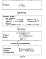
- the method for configuring the product comprises:
- Figure 1 sketches these steps.
- the figure shows a specific product (a bike), a specific form for the product model (a textual description), a specific virtual table (a Boolean Decision Diagram), and a specific interactive configuration process. It is clear to the person skilled in the art that the invention is not limited to these specific choices.
- the product model is used to describe what components the product is composed of and the inter-dependencies between these components.
- the product model will often define a set of product variables, the domain of each of these variables and a set of rules.
- Each product variable represents a component or an attribute.
- the domain of the product variable corresponds to the possible alternatives for the component.
- the domain of the product variable corresponds to the possible values for the attribute.
- the possible domains of the product variables include the discrete as well as the continuous domains. The inter-dependencies between components and attributes are expressed as rules and typically formulated as formulas over the product variables.
- An example of a product model is a product model of a computer, composed of a motherboard (three different alternatives), a CPU (two alternatives), and a harddisk (two alternatives). Since a CPU is connected to a motherboard using a slot, the slot type is an important attribute of both the CPU and the motherboard and since a harddisk is connected to a motherboard using a specific controller type, the controller type is also an important attribute.
- a computer product model is a textual example of a computer product model:
- the first section declares types that will be used to define the types of product variables.
- the next section declares product variables. These variables each have an identifier and a type.
- the type system for this example comprises atomic constructs as well as record construction ( ⁇ ... ⁇ ) and enumerated types (...
- the cpu is a product variable comprising a record consisting of a name and a slot, and this slot is of type cpu-slot-t.
- cpu- slot-t is declared as an enumerated type comprising the following two alternatives: SLOT-1 and SLOT-A.
- the private and public modifiers are used to control what components or attributes that are presented to an end-user during configuration (further details are given below).
- the third section declares the rules. These rules are general Boolean formulas over the product variables, and all rules must be satisfied for a consistent configuration. Generally, the rules can express any relationship between product variables, but the concrete rules presented in this example can be thought of as divided into two different categories:
- a configuration comprises the selection of a concrete value for all public parts of product variables.
- this comprises the selection of a motherboard name, a CPU name, and a harddisk name.
- a consistent configuration of the computer is a configuration satisfying the rules of the computer product model.
- An example of a consistent configuration is the selection of motherboard. name to Abit-BX6-ATX, cpu. name to Intel-Celeron-A-366MHz and harddisk. name to IBM-Deskstar-25GP-10,1GB.
- the product model is represented textually.
- the invention is not restricted to such a representation. Instead, the complete representation of the product model can be divided between multiple representations.
- An aspect of the invention combines product descriptions with product tables to obtain the complete product model.
- the product description is generally used to capture the structure of the product by defining the components and their attributes, and the product tables are generally used to capture the concrete alternatives for the components as well as the concrete values for the attributes.
- the example computer product model can be divided into a product description and three product tables.
- the product description consists of the same sections as the original computer product model, but the attribute rules have been removed:
- the first table defines attributes for the motherboard component: motherboard.name motherboard.slot motherboard.controller Abit-BX6-ATX SLOT-1 IDE open-AX6BP-ATX SLOT-1 SCSI Aopen-AK-72-KX133-ATX SLOT-A IDE
- the second table defines attributes for the harddisk component: harddisk.name harddisk.controller IBM-DeskStar-25GP-10,1GB IDE Seagate-Barracuda-9-9,1GB SCSI
- the third and last table defines attributes for the cpu component: cpu.name cpu.slot Intel-Celeron-A-366MHz SLOT-1 Athlon-AMD-500 SLOT-A
- a textual product model can be obtained from a product description and a set of product tables by the following method:
- the table is translated to a rule using the key observation that a table can be viewed as an expression on disjunctive normal form.
- a table with n rows and m columns is translated as follows:
- a convenient extension is to add table filters mapping values in the product table to values in the product description.
- An example of such a filter maps specific prices in the product table (such as $100, $223, $817) to price levels in the product description (such as cheap, reasonable and expensive). Such a mapping will typically map all prices in a given interval to the same price level.
- the translation to a rule does not need to be performed explicitly.
- An aspect of the invention is that the translation instead can be done on the fly during the construction of the virtual table.
- the preferred embodiment of the product model is composed of a product description and a set of product tables.
- the product description is given as an XML 1.0 document.
- the product tables are combinations of ODBC data sources and SQL queries.
- the XML document is defined using the document type declaration (DTD) shown in Annex A 10. Basically, a product description contains:
- the rules comprise structured expression: atomic expressions such as Booleans (true, false), values from bounded sub-ranges (0, 1, ..., n) as well as compound expressions built from arrays, record expressions and enumeration (sum) expressions. Furthermore, arithmetic and Boolean operators are provided. In the preferred embodiment the allowed arithmetic operations include addition, subtraction and multiplication and the multiplication operation is only allowed when at least one of the operands is a constant. At first the allowed types of arithmetic operators seem odd, but as we shall see later this choice works very well together with the preferred embodiment for the virtual table.
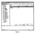
- ConfigItStudio is such a graphical user interface, see screen-shot in Figure 2 .
- the screen-shot shows the ConfigItStudio product model editor, while editing a pc product model.
- the tree view in the left area of the screen-shot is a tree view of the product description and is closely related to the XML document type declaration. (On the screen-shot, the term "template” is used for a type declaration and the term “constraint” is used for a rule.)
- the area to the right shows details for the selected vertex in the tree and can be used for manipulating the vertex.
- the menu on the top of the screen-shot can be used to build (the "Compile” menu) a virtual table for the product model (see below) and run a virtual table server (the "Run” menu) for interactive configuration over the Internet (see below).
- An important aspect of the invention is the process of transforming a product model to a compact and efficient representation.
- This process we refer to as virtual tabulation and the resulting representation we call a virtual table.
- the purpose of the transformation is to first find a way of encoding and finding all solutions to the configuration problem and then tabulate them virtually in a virtual table such that information relating to the configuration problem can be obtained by efficient queries to the virtual table.
- the encoding involves finding an encoding of the components of the product model and a corresponding encoding of the rules.
- a DAG will represent all the rules, such that enquiries about valid solutions to the rules can be performed efficiently.
- the virtual table consists of this DAG and information relating to the relationship between product model and DAG.
- the most vital part of the virtual table is the DAG representing each an every consistent configuration. Since there, for a real-life product model, are incredibly many such configurations the DAG must somehow capture these configurations in an implicit manner. Still, the DAG must represent exactly these configurations (ie., without "loosing precision").
- the requirements to the DAG can be divided into two categories:
- Boolean Decision Diagram is a DAG comprising nodes each containing a single Boolean variable. It is well known from the area of formal verification of hardware circuits that BDDs can be used to encode arbitrary Boolean functions of type (where n is the number of Boolean variables):
- Boolean product models These functions are isomorphic to configuration-sets for "Boolean product models.” (By a "Boolean product model” we think of a product model where the values of the product variables are limited to true and false). Therefore, if it is possible to encode general product models as such Boolean product models, and, furthermore, if the needed configuration algorithms can be be expressed in terms of basic BDD operations, then it is possible to 1) represent the virtual table of general product models using BDDs and 2) use this virtual table for performing actual configuration of general products.
- BDDs are the preferred embodiment of the DAG.
- the invention is not limited to such DAGs.
- Many other DAGs have representation and algorithms that can be viewed as sets and operations on sets, respectively.
- the DAG must be carefully chosen based on the language for expressing the rules in the product model.
- Difference Decision Diagrams See M ⁇ ller et al: Difference Decision Diagrams. In proceedings Annual Conference of the European Association for Computer Science Logic (CSL), September 20-25 1999 . Madrid, Spain.
- CSL Computer Science Logic
- the immediate advantage is that we thereby have a method of encoding product models where the rules comprise (a restricted subset) of quantified expression over variables with continuous domains.
- the disadvantage is that the algorithms are less efficient (satisfiability of the rules that can be encoded turn out to be pspace-hard).
- the flattened product model is the result of this static expansion and is created so that it is suitable for encoding using BDDs.
- the static expansion is performed by flattening the type hierarchy.
- the result is a flattened product model and a symbol table relating the product model and the flattened product model.
- the flattened product model is obtained by 1) the removal of record expressions, 2) simplification of the domains and 3) encoding in Boolean form.
- the removal of record types is done by, for each product variable comprising record types, replacing the product variable with a list of flattened variables. Furthermore, all expressions over this product variable are replaced by expressions over the flattened variables. After this replacement all records have been removed from the product model. For the computer product model, this step results in the following product model. (Recall, that motherboard was a product variable of record type composed of name, slot and controller):
- the second step of the flattening of the product model comprises simplification of the domains of the flattened variables. All flattened values are turned into numbers, and the domain of each flattened variable is turned into an interval. For example, for the cpu_slot a value 0 is used instead of SLOT-1 (which was the first alternative for the cpu slot) and a value 1 is used instead of SLOT-A (the second alternative). For the computer product model, the resulting product model is:
- the last step of the flattening of the product model comprises the encoding of the product model in Boolean form.
- Each flattened variable is replaced by a list of Boolean variables and each rule is replaced by a new rule over these Boolean variables.
- a flattened variable with a domain of type 0 .. n is replaced by [log 2 ( n +1)] Boolean variables.
- a unique assignment to these Boolean variables is chosen for each of the n + 1 values.
- two Boolean variables are needed: X 0 and X1.
- Each rule is now replaced by a new rule over the Boolean variables obtaining the flattened product model.
- the flattened product model for the computer product model is:
- This symbol table comprises two tables.
- the first table contains information about type, the domain of each of the flattened variables as well as the Boolean variables used to encode values for this variable.
- this table is: Flattened variable Type Integer domain Boolean variables motherboard_name public 0..2 X0, X1 harddisk_name public 0..1 X2 cpu_name public 0..1 X3 motherboard_slot private 0..1 X4 cpu_slot private 0..1 X5 motherboard-controller private 0..1 X6 harddisk_controher private 0..1 X7
- the second table relates the flattened values, their integer values and the unique Boolean assignments.
- this table is: Flattened variable Flattened value Integer value Boolean values motherboard_name Abit-BX6-ATX 0 0,0 motherboard_name Aopen-AX6BP-ATX 1 0,1 motherboard_name Aopen-AK-72-KX133-ATX 2 1,0 harddisk_name IBM-DeskStar-25GP-10,1GB 0 0 harddisk_name Seagate-Barracuda-9-9,1GB 1 1 cpu_name Intel-Celeron-A-366MHz 0 0 cpu_name Athlon-AMD-500 1 1 motherboard_slot SLOT-1 0 0 motherboard_slot SLOT-A 1 1 cpu_slot SLOT-1 1 0 0 cpu_slot SLOT-A I 1 motherboard_controller IDE 0 0 motherboard_controller SCSI 1 1 harddisk_controller IDE 0
- the construction of the DAG is now performed.
- the preferred embodiment is a (Reduced Ordered) Binary Decision Diagram.
- Boolean Decision Diagrams for the representation of Boolean formulas is well known.
- Boolean Decision Diagrams see [ Cristoph Why Thorsten Theobald: Algorithms and Data Structures in VLS1 Design, Springer 1998 ].
- BDDs has a well known graphical representation.
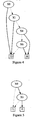
- Figure 5 is an example of this representation.
- the figure is a BDD over two variables X 0 and X 1 .
- the algorithm FULLONESAT( u ) computes a new BDD v fulfilling v ⁇ u such that the BDD u has exactly one satisfying assignment (naturally, u must be feasible, i.e., contain at least one solution).
- the algorithm ANYSAT( u ) returns a satisfying assignment of values to the variables in u (again, u must be feasible).
- the algorithm SATCOUNT( u ) returns the number of assignments satisfying u .
- the construction of the BDD representation takes its basis in the flattened product model.
- a suitable ordering of the Boolean variables are chosen. The choice of this ordering is important for the size of the constructed BDDs. In the preferred embodiment, the ordering is chosen by keeping Boolean variables representing the same flattened variable next to each other.
- a suitable ordering for the computer product model is X 0 ⁇ X 1 ⁇ X 2 ⁇ X 3 ⁇ X 4 ⁇ X 5 ⁇ X 6 ⁇ X 7 .
- each of the rules is encoded as a BDD.
- the encoding is performed using the well known M K and APPLY algorithms.
- the set R refers to the set of rules, each rule encoded as a BDD.
- a domain constraint representing the possible Boolean variable assignments is made for each flattened variable.
- the preferred method for building these BDDs is also by the use of the MK and APPLY algorithms.
- the set D refers to the set of domain constraints, each domain constraint encoded as a BDD.
- the BDDs built at this stage will be used as building blocks for the creation of one big BDD representing all rules R and all domain constraints D .
- ⁇ r ⁇ R r denotes the result of conjoining together all elements r from R .
- a BDD representing all possible consistent configurations is obtained by conjoining all the BDDs for all rules and all domain constraints.
- C all dcf ⁇ R all ⁇ D all .
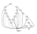
- any path leading from the top vertex to the terminal 1 represents one or more assignments of Boolean variables that makes up a consistent configuration of the computer. More assignments are represented if some variables are absent on a path: these can take on any of the values 0 or 1 and still result in a consistent assignment. Using the symbol table it is possible to relate this information to the original flattened variables.
- a graph ( V , E ) is constructed comprising vertices V , each labelled with one flattened variable, and edges E , each labelled with one rule.
- the graph is undirected, but more than one edge can connect two vertices (a multi-graph).
- the graph contains:
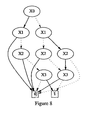
- a strongly connected component graph is created (see for example: [ Cormen, Leiserson, Rivest: Introduction to Algorithms, p. 488-490 ]).
- S denote the set of strongly connected components.
- Each of the strongly connected components comprises a sub-graph.
- G i ( V i , E i ) comprise the i'th of these sub-graphs (for 1 ⁇ i ⁇
- the last step is preferably performed by the algorithm ORDERRULES shown in Algorithm 4.
- This algorithm takes as input 1) the list of ordered flattened variables O and 2) the edges E .
- ⁇ where invariantly: ⁇ i , j ⁇ 1 ... V : i ⁇ j ⁇ ⁇ i ⁇ freevars F j ⁇ .
- Equation 1 and Equation 2 we can determine the set of consistent configurations C pub by 1) starting with a BDD for the domain constraints D all , 2) repeatedly, for increasing i (1 ⁇ i ⁇
- This task is performed by the algorithm CONJOINEXISTS which is preferably implemented as shown in Algorithm 5.
- the computer product model does not contain any arithmetic operations. However, as described earlier, the preferred embodiment of the product model does allow certain carefully selected arithmetic expressions: addition of two expressions, subtraction of two operations, and multiplication of an expression with a constant. These arithmetic operations are allowed because 1) they turn out to be useful during product modelling and 2) at the same time efficient BDD operations for encoding such expressions exist.
- a product table (typically represented in a database) can be used to represent a rule in an adequate manner. It is not necessary to first explicitly translate the product table to a textual rule and thereafter translate the rule into a BDD. Instead a BDD can be built directly from the product table.
- the preferred embodiment for this process is the algorithm VIRTUALIZETABLE shown in Algorithm 6.
- the algorithm tabulates each cell, builds a BDD for this cell and accumulates the results of the tabulation in temporary BDD nodes.
- the auxiliary function VIRTUALIZECELL builds a BDD for a specific cell.
- the implementation of this algorithm will use the symbol table for finding out how to map flattened variables to Boolean variables.
- Table filters are easily added to this method by adding information relating to the table filters to the symbol table and changing the auxiliary function VIRTUALIZECELL to use this information.
- the computer product model contains values of enumerated type (for example [ IDE
- a more general type that can also be encoded using BDDs is the sum type (known from many classic type systems). This compound type allows a tag (as in the enumeration case) and a value (which can have any type).
- An example of a sum type modelling that an extra harddisk can either be absent or present (with a specific type) is:
- Possible values for extraharddisk are ABSENT, PRESENT (IDE) and PRESENT (SCSI) .If we want to encode one of these values we must 1) capture whether we have selected the ABSENT or PRESENT tag and 2) in the latter case which sub-value (IDE or SCSI) we have selected. The preferred embodiment is to encode these two parts separately. In this specific case: One Boolean value ( P ) indicating that the extra harddisk is PRESENT and one Boolean variable ( T ) indicating that the type is SCSI.
- the virtual table is now used for performing a configuration. Without limiting the invention a user is normally involved in this process. The user interacts with a computer program, a configuration assistant, interfacing to the virtual table. Generally, the configuration session performed by the user and the computer program can be viewed as an interactive iterative configuration where the configuration assistant guides the user through the configuration process:
- the "protocol" for such a configuration session can be constructed in many ways. Without limiting the invention the session will typically be an iterative process comprising the following steps (seen from the perspective of the configuration assistant):
- the iterative process goes on until the user decides to terminate the session.
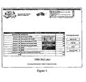
- Figure 3 is a screenshot of a user interface for a pc product model.
- the user interface allows the user to see already performed selections (for example, the user has selected the alternative IBM DeskStar 25GP 10 ,1GB for the component Harddisk 1), see what alternatives that are available (here, by a "pop-up" window, currently showing CPU alternatives), and which of these alternatives that are compatible with all earlier selections (here, by using a black background colour).
- the user can select an alternative for a component, de-select earlier made configurations, etc.
- Two additional features make the life easier for the user:
- a common case is to present such a user interface in a web browser, obviously allowing the use of the Internet for communication.
- the virtual table can either be placed on a virtual table server or on the client running the web browser.
- the configuration assistant will comprise a server and a client thread (running in parallel, communicating through the Internet).
- the configuration assistant will typically run solely inside the web browser. Both approaches are feasible and the method of deployment must be based on which properties are required for the given configuration session. However, the first approach is the preferred embodiment.
- the variable S is an ordered list of selections, each selection comprising a pair ( v , d ) where v is a flattened variable and d is a flattened value.
- the selections generally represent a non-empty set of the consistent configurations available in the virtual table.
- S is the empty list, representing the complete set of consistent configurations in the virtual table.
- the command can be the selection of one of the selections that were compatible with S , the de-selection of a selection already in S, the forcing of a selection, or, if a selection is made for all public flattened variables, exiting the configuration.
- the preferred embodiment for the interactive configuration system is a configuration assistant comprising a server and a client thread running on a virtual table server and in a web browser, respectively.
- a configuration assistant comprising a server and a client thread running on a virtual table server and in a web browser, respectively.
- the basic BDD algorithms utilises a programming technique known as dynamic programming. As a consequence results of computations on the BDDs are being cashed (depending on available memory, etc). This implies that a re-computation with the same arguments generally will run in constant time. A couple of the algorithms utilises this: Instead of maintaining tables with temporary BDDs the underlying operations are called (with the same arguments) and the result are (generally) available in constant time. This approach further more allows for the implementation of a "state-less" server.
- the first four key algorithms concern the combinations of the virtual table and selections.
- the first algorithm CONFIG1 shown in Algorithm 7 is used for combining the virtual table ( C actual ) with one selection.
- the selection comprises a flattened variable v and a value d .
- First a BDD u is built, representing the selection. This BDD is build by 1) determining the Boolean variables ⁇ v 1 , ... , v n ⁇ representing v and the Boolean values ⁇ d 1 , ...
- the algorithm CONFIGCHECK shown in Algorithm 9 takes care of this.
- the ordering of the selections in S new is used for prioritising selections.
- CONFIG1 is applied to the individual selections.
- the selections are added to a list of consistent selections.
- the selections is "rejected" and the previous set of configurations are kept.
- the rejected selections are put together in a list.
- the algorithm are finished it returns a BDD representing a non-empty set of configurations. Under the (reasonable) assumption that the initial virtual table is non-empty this algorithm will invariantly return a BDD representing a non-empty set of configurations.
- the list of consistent and rejected selections is furthermore returned.
- the next algorithm CONFIGIT shown in Algorithm 10 is used for 1) restricting the set of configurations based on a set of compatible selections and 2) automatically selecting compatible values for the remaining product variables.
- the algorithm starts of as CONFIGCONSISTENT yielding a BDD representing a non-empty set of solutions C actual .
- the known BDD algorithm FULLONESAT is used.
- This algorithm builds a BDD comprising a single path in from C actual . This BDD will represent exactly one configuration.
- the known BDD algorithm ANYSAT is then used to obtain the Boolean selections represented by this path. By “backwards" use of the symbol table the product selections is determined.
- the algorithm CONFIGCOUNT shown in Algorithm 11 counts the number of consistent configurations in a virtual table.
- the algorithm SATCOUNT is used to determine this number. However, three important details for being able to just return this number are:
- CONFIGCOUNT on the BDD representing the virtual table of the computer product model returns the number of consistent configurations of the computer, three. This number can also be found by counting the number of paths leading to 1.
- the algorithm DETERMINEDOMAIN shown in Algorithm 12 determines, for a given flattened variable v i and a virtual table C actual , which possible values can be selected.
- the algorithm works by existentially quantifying out all the Boolean variables X except for the Boolean variables ⁇ i B representing v i .
- the result of these existential quantifications is a BDD that - viewed from a configuration perspective - represents a virtual table.
- This virtual table has the nice property that it only contains one column (the column with the possible values for v i ). Since a product variable by virtue of the shape of the virtual table cannot have any interdependencies with other variables (only one column) the domain can be determined simply by listing the elements in the virtual table. This is done by: 1) Finding the set of assignments of the Boolean variables ⁇ i b in the virtual table. 2) translating each of these to flattened values.
- An illustrating example is to determine the domain of the motherboard_name flattened variable for the initial virtual table of the computer product model.
- the Boolean variables representing motherboard _ name is X0 and X1. All other Boolean variables are existentially quantified out yielding the BDD shown in Figure 10 (structural equivalent to Figure 5 ).
- This BDD has three assignments of Boolean variables X0 and X1: (0,0), (0,1) and (1,0).
- the algorithms described above can be used to implement many different configuration systems. We will now show how they are used in a configuration assistant comprising a server and a client thread communication over a network such as the Internet.
- the virtual table is located on a virtual table server that performs the needed computations during configuration.
- a client is used for presenting a user with information regarding the configuration process and for querying about selections, etc.
- the preferred implementation comprises the two threads CONFIGCLIENT (on the client side) and the algorithm CONFIGSERVER (on the server side).
- the two algorithms are shown in Algorithm 13 and Algorithm 14, respectively.
- the CONFIGCLIENT runs during one configuration session.
- the algorithm returns with the obtained configuration. (The "return” is in real life typically replaced by sending the result to an order placement module, etc.)
- the CONFIGSERVER algorithm is non-terminating. Upon start it enters a loop awaiting a client to serve. When it receives a configuration command from a client it computes a result and immediately returns this result to the client. Thereafter it loops back to start, awaits for a new command from a new client (or possibly the same), and so on.
- Communication is specified using standard primitives such as SEND and RECEIVE.
- the protocol is that: Initially the client sends a configuration command to the server. The server receives this configuration command and computes the result. This result is passed back to the client. The client receives the result, provides information to the user and queries the user for a user command (a selection, exiting, etc.). Upon receiving this user command a new configuration command is send to the server, and so on.
- the client is provided a single argument: the set of public flattened variables.
- the algorithm runs as follows.
- the purpose of the server algorithm is to provide the computational needs for the client algorithm and can be viewed as glue code between the client and the key configuration algorithms described earlier.
- the server algorithm is provided the following arguments:
- variable S actual is an (ordered) list of selections the user has made. Each of these selections comprises a pair ( v , d ) where v is a public flattened variable and d is a value from the domain of v .
- the BDD C actual represents all consistent configurations with respect to the actual selections S actual .
- Annex A XML Document Type Declaration for the Product Description
Abstract
Description
- The present invention generally relates to the task of configuring a configurable device composed of several parts. The parts have inter-dependencies and as a consequence there are certain requirements regarding selection of the parts in order to build a working product. Generally the process of determining whether a collection of parts will work together is a complex task and a computer program is often used to help solving this task. Such a computer program must work with the inter-dependencies in an efficient yet precise manner. This invention is related to how an implementation can be made of such a computer program.
- A complex product is composed of several components. A product model of a complex product is often made by looking at the product as being composed of several generic components. For each of these components there is a group of specific alternatives.
- An example of a product model of a bike is: A bike is build of the following components: a frame, a front wheel, a rear wheel and a gear set. The following alternatives for the frame component exists: carbon male, standard female, standard male, off-road. For the front wheel component: slick, off-road. For the rear wheel component: slick, off-road. And, finally, for the gear component: internal three speed, external 10 speed.
- In the context of configuration the word "component" is not to be understood only as the generic description of a physical component. It could also be attributes such as colour and shape, parameters such as number of gears and horsepower. A component could also be understood as "need attributes", which express a need from the user of the configurator rather than a property of the product, such as the type of a bicycle (off-road, city bike, heavy duty bike etc.), the taste of a user (fashionable, classic, childish), or the price or weight or similar properties of interest for a user of a product.
- A specific alternative must be selected for each of the components to build the complex product. A number of selections is called a partial configuration of the product. The complete selection of an alternative for each component is called a complete configuration (or just a configuration) of the product.
- The number of possible configurations of the product grows rapidly with the number of components the product is composed of. For example, to configure the example bike, one must select among four frames, two front wheels, two rear wheels and two gears. Thus there exists 4 x 2 x 2 x 2 = 32 different configurations. In realistic examples, this number quickly grows beyond millions.
- Due to incompatibilities, etc., all combinations of the alternatives will not work. If we consider the bike example, it might be the case that the front and the rear wheel must be of the same type. Another requirement could be that the carbon male frame is the only frame allowing the external 10 speed gear. The descriptions of these incompatibilities between the alternatives are called the product requirements. The product requirements are often expressed as rules defining compatibilities between components. A configuration is said to be consistent if all requirements are satisfied. For the bike example, there are 10 different consistent configurations (8 configurations with an internal three speed gear and 2 configurations with an external 10 speed gear) out of the 32 possibilities.
- In general, the requirements can be complicated and hard to overview for a human, and it is a complex task to determine a consistent configuration. A computer program can be of great help during the configuration process and generally works by checking a user's selections against the rules. This checking is generally hard to perform: either the checking may take unreasonable long time or the results of the checks may be imprecise. There are at least two different ways of treating the rules.
- Explicit Enumeration This method typically uses bit-vectors to represent all possible consistent configurations. All possible configurations are tested against the rules and the configurations that turns out to be consistent are enumerated in a list, typically using a hash-table of bit-vectors. One key limit with this approach is that the number of configurations grow rapidly when the number of available components rises (typically, the number of configurations grows exponentially with the number of components). This means that the amount of memory which is required is extremely large and the method is not applicable to large product models. Another problem is that even if the number of configurations is small enough to be kept in memory, the algorithms need to traverse and treat each possible configuration independently yielding running times that are linear in the number of configurations.
- Rule/Constraint Propagation When a configuration selection is made, the rule database is searched in order to check for consistency. The search time is unpredictable and therefore often limits are imposed on the allowed time consumption in order to ensure a timely response to the user. In order to meet the time limit, the search must often be ended prematurely without the full and correct result being known. The search is based on the accumulation of information by repeatedly applying the rules from the rule base to the selections that have been made. This is often very costly. Furthermore, the search time, and thus the quality of the search, is highly dependent on exactly how the rules have been formulated.
- State-of-the-art tools apply the two techniques described above. They have been developed as sales assistant tools and are now being adapted to the Internet. On the Internet there is no human sales assistant available to compensate for inaccuracies and lack of information. The user is going to execute the whole sales process himself, which imposes hard requirements on the quality of the sales system. The system must have a fast response time and ensure that the results are still accurate. For example, it must never be the case that the user is lead to select an alternative that is inconsistent (i.e., some of the rules become violated) with the user's earlier selections.
- State-of-the-art tools have difficulties obtaining precise results and at the same time ensuring desirable response times (while dealing with complex products and allowing the system to handle many concurrent users.)
- A number of patents are related to product configuration.
-
US 6,115,547 discloses a product configuration comprising a specific way of caching earlier configurations improving performance of a configuration program. -
US 5,675,784 discloses a product configuration comprising a data structure (a "three tiered hierarchical data structure") to be used for modelling products. -
EP 0770239B1 discloses a product configuration comprising an expert system. This configuration method is related to rule/constraint propagation. -
US 5,206,949 discloses a product configuration comprising a database search and retrieval system. -
US 5,844,554 discloses a product configuration comprising a graphical user interface method for designing g the product model. -
US 5,987,473 discloses a product configuration comprising a method for performing interactive configuration via a network. -
US 5,995,979 discloses a product configuration comprising a method for allowing a user to select an entry in a database over a network. -
US 5,996,114 discloses a product configuration comprising a method for handling the many possible configurations. This configuration method is related to Explicit Enumeration. -
US 5,745,765 discloses a product configuration comprising a method for allowing a user to select a consistent configuration. - The invention described in this patent applies a known technique symbolic model checking known from formal verification of hardware circuits to solve the computational problems inherent in developing a program for computer assisted configuration. Symbolic Model Checking is described in [K.L. McMillan Symbolic Model Checking: An Approach to the State Explosion Problem].
- The invention relates to a method of configuring a configurable device comprising a number of components according to
claim 1, the method comprising: - providing, for each component, information relating to a group of alternatives for the component,
- defining rules relating to compatibilities between alternatives from different components,
- representing the rules in a Directed Acyclic Graph (DAG), and
- iteratively configuring the configurable device by repeatedly:
- choosing a component,
- selecting an alternative from this component's group of alternatives,
- checking the DAG whether the alternative selected is compatible with other chosen alternatives from other components.
- In the present context, a component is not to be understood only as the generic description of a physical component. It could also be attributes such as colour and shape, parameters such as number of gears and horsepower. A component could also be understood as "need attributes", which express a need from the user of the configurator rather than a property of the product, such as the type of a bicycle (off-road, city bike, heavy duty bike etc.), the taste of a user (fashionable, classic, childish), or the price or weight or similar properties of interest for a user of a product.
- A rule may relate to the compatibility of an alternatives from e.g. two different components of the product. However, it may be preferred that the rule relates to compatibility of an alternative from a larger number of components. In an extreme, but in no way unthinkable, is a rule which relates to a product comprising an alternative from each of the components.
- Naturally, the information relating to an alternative or a group of alternatives may be information relating to similarities or differences thereof. Normally, this information will be information relevant vis-a-vis the other components and/or the alternatives of the other components.
- When having represented the rules in the DAG, it is no longer necessary to check the (normally very large number of) rules. Instead, the DAG may be traversed, analysed or even amended in accordance with information relating to selected/chosen alternatives. This procedure may be made much faster than the individual checking of a number of rules.
- In the present context, an alternative is "chosen" if it has been "selected" and found to be part of the combined product which is sought configured - that is, normally, when the selected alternative has been found to be compatible with at least one chosen alternative.
- The iterative configuring may be ended when an alternative is chosen for each component and preferably when the chosen alternatives of the components are compatible.
- It may be desired to, before the selecting of an alternative, use the DAG to determine, for at least one of the components, a subset of alternatives for the component, so that each of the alternatives in the subset is compatible with the other chosen alternatives from the other components, and providing this information to a user.
- In this situation, the user may desire information relating to the compatibility with a number of alternatives for a given component - compatibility with the alternatives already chosen - in order to, normally, select a compatible alternative from that group. This subset may relate to preferences of the user, such as dimensions, colours, manufacturer, place of manufacture, etc.
- In may ease the interaction with the system if the information to the user is provided as computer generated speech. This is done by providing a system with a speech synthesizer and the providing of information to a user further comprises
- providing the information by speech generated by the speech synthesizer.
- The steps of selecting a component and an alternative further comprises, for each of the components:
- using the DAG to check which of the alternatives of the component that are compatible with at least one of the chosen alternatives of each of the other components (i.e. those for which alternatives have been chosen),
- providing a user with this information,
- allowing the user to select one of the alternatives that were compatible with at least one of each of the other component's chosen alternatives.
- Thus, in this manner, information is provided relating to the compatibility of all alternatives for the component - with the alternatives already chosen, in order for the user to quickly be able to progress in the configuring of the configurable device.
- In addition, it may be desired that the steps of selecting an alternative and checking the DAG further comprise the steps of:
- selecting or defining a subgroup of alternatives to the chosen component,
- checking the DAG for which of the alternatives in the subgroup that are compatible with chosen alternatives from other components, and
- providing information relating to which of the alternatives in the subgroup are compatible with chosen alternatives of other components.
- One situation where this may be convenient is the situation where the user has not yet decided on a specific alternative, but he provides a subgroup of alternatives that are checked for compatibility with chosen alternatives of other components. This information can be used to further guide the user during configuration.
- Another approach that can be beneficial is to:
- at least once, defining information relating to limiting the alternatives of at least one of the components, and
- checking the DAG for which of the alternatives of the components is compatible with the limiting information.
- This limiting information may be provided by a user, and information relating to which of the alternatives of the components are compatible with the limiting information may be provided to the user.
- Such limiting information may be information relating to compatibilities between alternatives from different groups desired by the user.
- The iterative configuring may also be ended upon request from a user, normally at a point therein where there has not been chosen/selected an alternative for each component, or where the alternatives selected/chosen are not fully compatible. Then, information may be provided relating to all possible compatible products comprising at least one chosen alternative for each of the products for which an alternative has been chosen - and this information may be provided to the user.
- Thus, the user may end the configuration and then be informed of the total number of compatible products available comprising the alternatives chosen.
- Also, the iterative configuring may comprise the step of obtaining the number of all possible compatible products comprising at least one chosen alternative for each of the products for which an alternative is chosen and providing this information to the user. In this manner, the user may be constantly informed of the number of products available comprising the alternatives chosen. It should be noted that the user will be able to actually select or choose more than one alternative for a given component. In this situation, the compatibility check will be that of each such alternative and the total number of potential final products will relate to the sum of potential final products comprising one of those alternatives.
- The step of representing the rules in a DAG comprises representing the rules in a graph comprising:
- at least one terminal node,
- a plurality of nodes comprising:
- a mathematical expression having a plurality of possible disjoint outcomes and
- a number of pointers corresponding to the number of possible outcomes of the expression, wherein:
- a pointer of at least one of the nodes points to another of the nodes, and
- a pointer of at least one of the nodes points to one of the at least one terminal node,
- at least one of the nodes being a top-most node from which one or more paths are defined from a top-most node to one of the at least one terminal node via one or more of the nodes and the pointers thereof, each node being part of at least one path.
- This is a standard manner of representing rules in a DAG. Thus, the rules are represented as mathematical formula and are introduced into one or more nodes. Each rule comprises one or more outcomes and the pointers of the nodes each relates to such an outcome. Thus, different outcomes of the rules will provide the traversing of different paths through the graph/DAG.
- Thus, the step of representing the rules in the DAG may comprise providing one or more of the nodes with mathematical expressions each comprising a mathematical operator, each operator describing how the rules represented by the nodes pointed to by the pointers of the pertaining node are to be combined in order to represent the combined set of rules.
- The step of representing the rules in the DAG comprises representing the rules in a graph comprising a number of the nodes, the mathematical expression of which is a Boolean expression and/or a variable.
- Also, the step of representing the rules in the DAG may comprise representing the rules in a graph comprising nodes, the mathematical expressions of which are ordered according to a given ordering such that, for each node, the expression of an actual node is of a lower order than the expressions of any nodes pointed to by the pointers of the actual node.
- Providing an ordering facilitates a number of operations on the DAG, such as searching in a DAG and combining two DAGs.
- In order to maintain a suitable DAG, the representing of the rules in the DAG may further comprise the steps of:
- identifying a first and a second node having the same expression and the pointers of which point to the same nodes, and
- having pointers pointing to the first node point to the second node.
- In that situation, two nodes actually representing the same contents are reduced to only one.
- A preferred manner of providing the DAG is one wherein the step of representing the rules the DAG comprises:
- representing each rule as a logical expression,
- from each logical formula constructing a partial DAG representing the set of possible solutions to the formula,
- constructing the DAG representing all the rules from the partial DAGs representing each of the logical formulas.
- This method is rather simple in that the constructing of a partial DAG from a rule is normally a simple task - and the combination of DAGs is a well-known technique, which is, actually, facilitated if the above ordering of the expressions is used.
- Preferably, the step of providing the information relating to the alternatives for each component comprises:
- selecting Boolean variables for representing the individual alternatives of the component,
- providing an encoding for each of the alternatives of the component as a combination of Boolean values for the Boolean variables.
- Then the step of representing each rule as a logical formula/expression may comprise providing the Boolean variables relating to the alternatives to which the rule relates and interrelating the variables in accordance with the rule.
- The step of representing the rules in the DAG comprises providing at least one type of terminal node and wherein, for each path comprising a such terminal node, the combination of all expressions and all pertaining outcomes relating to the pointers of the path relate to either compatible components or non-compatible components.
- It is clear from the above that the variables of the mathematical expressions of the nodes of a path relate to a number of alternatives of components. It is also clear that the path is also defined by the pointers linking the nodes together and that those pointers each relate to an outcome of a mathematical expression - and thereby to a given relation between variables. Thus, the information of a path - including the information of the terminal node - preferably provides information as to a product, the alternatives thereof and the compatibility therebetween.
- Preferably, the step of representing the rules in the DAG comprises providing a first and a second type of terminal nodes and wherein:
- for each path comprising a terminal node of the first type, the combination of all expressions and all pertaining outcomes relating to the pointers of the path relate to a compatible product, and
- for each path comprising a terminal node of the second type, the combination of all expressions and all pertaining outcomes relating to the pointers of the path relate to a non-compatible product.
- In this situation, the first type of terminal node may be adapted to represent "true", "one" or "1", and the second type of terminal node may be adapted to represent "false", "zero" or "0".
- In general, the step of selecting an alternative may comprise identifying Boolean variables relating to any other alternative(s) of the component and nodes comprising expressions relating to such other altemative(s) and, in the DAG, identifying paths comprising such nodes and altering any terminal node(s) thereof of the first type to terminal node(s) of the second type. Thus, such paths then may relate directly to "incompatible products" in that these products are no longer interesting - the selected alternative normally not being compatible with the other alternatives for the same component. If the user selects a subgroup of alternatives for that component, the same procedure is, naturally followed as to those alternatives of the component which are not in the subgroup.
- In this situation, the computing of the number of possibilities of different choices may be performed by the following steps applied to the DAG and for each top-most node:
- starting from the topmost node and iteratively finding the number of possibilities represented by the actual node, by performing the steps of:
- if the node is a terminal node, providing a "1" if the terminal node is of the first type and a "0" if it is of the second type,
- else: finding the number of possibilities represented by each node pointed to by a pointer of the actual node, and therefrom computing the number of possibilities represented by the node.
- Normally, the number of possibilities represented by a node having, for example, a first number of possibilities represented by one pointer and a second number of possibilities by another pointer can be computed as the sum of the first number of possibilites and the second number of possibilites. However, if, due to a size reduction of the DAG (such as "local reduction"), implicit nodes are placed (implicitly) between the actual node and the node(s) pointed to by the first and/or second node(s) these implicite nodes must be taken into account when finding the number of possibilites represented by the actual node.
- If, during configuration, a selected alternative is not compatible with other, chosen alternatives, the step of checking the DAG may further comprise,
- providing information relating to other chosen alternatives which are not compatible with the selected alternative, and
- providing this information to a user.
- In this situation, the user may choose to actually enter or choose/select the selected alternative and then un-choose the or those alternative(s) which is/are not compatible therewith.
- A number of manners exist for actually providing the rules relating to the compatibilities. A preferred manner is one where at least one of the rules is defined by
- obtaining, by querying a database, information relating to alternatives relating of one or more components and/or information relating to compatibility between two or more alternatives to different components, and
- building one or more rules from the information obtained from the database.
- A simple manner of performing this is one wherein the database comprises a two-dimensional table having, in each of a plurality of rows thereof, information relating to a product comprising an alternative from each component, the alternatives being compatible, wherein the step of providing a rule comprises providing a rule relating to the information of each row and wherein the step of representing the rules in the DAG comprises providing a disjunction of the rules.
- Preferably, the step of checking the DAG whether a selected alternative is compatible with the chosen alternatives comprises searching the DAG for a path from a topmost node to a terminal node, the search comprising:
- starting with the top-most node as an actual node,
- iteratively, until the actual node is a terminal node:
- evaluating the mathematical expression in the actual node and determining the outcome thereof in view of the alternatives chosen from other components,
- selecting the pointer of the node representing the outcome,
- selecting, as the actual node, the node pointed to by the selected pointer.
- providing information relating to the chosen alternatives, and
- the information relating to the path represents that the choices are compatible.
- One simple manner of providing information from a path in the DAG is one providing, from the expressions of the nodes of the path, information relating to which altemative(s) of a given component has/have been chosen, and the information of compatibility of the product comprising those alternatives is given by the representation of the terminal node of the path.
- Thus, the information relating to the individual alternatives is derived from the expressions of the nodes and the pointers interconnecting the nodes - and the compatibility information is seen in the terminal node of the path.
- Thus preferably, the expressions related to nodes of the DAG are Boolean variables, the terminal nodes represent either "true"or "false", a path comprises one or more nodes each comprising a mathematical expression and a pointer to another node or the terminal node in the path, the information of the path relating to the identities of the variables in the mathematical expression(s) of the node(s) of the path and values or dependencies thereof, the identities and values/dependencies relating to chosen alternatives of components, the chosen components being compatible if the terminal node of the path represents "true" and the chosen components being incompatible if the terminal node of the path represents "false".
- A special situation exists where a component may be of a type which, naturally, has to be taken into account during the configuration but which may not be informative or relevant to e.g. a user performing the configuration. Thus, it may be desired to "hide" such components during the configuration.
- An example of a component which may be hided is the width of the hub of a bicycle wheel. This width is very important in that it describes the compatibility of a frame and a wheel, but a user configuring a bicycle does not need to pay interest to this point. The system may simply hide this component and make sure that the user is not able to perform selections which are contrary to an implicitely selected hub width (such as defined by an already chosen frame or wheel).
- In that situation, the step of representing the rules in the DAG may comprise:
- representing the rules in an actual DAG,
- selecting at least one of the components to be hidden,
- changing the actual DAG by:
- identifying nodes in the actual DAG comprising expressions relating to the selected component(s),
- removing these nodes from the actual DAG,
- adding nodes, not comprising expressions relating to the selected component(s), to the actual DAG so that the compatibilities implied by these component(s) are reflected by the actual DAG,
- providing the actual DAG as the DAG representing the rules.
- Thus, the DAG is simply altered in a manner so that an alternative of a hidden component which implicitely selects alternatives for other component will implicitely select these alternatives for the other components in a way so that subsequent compatibility checks will relate also to the "hidden" component even though the user will not be able to verify this.
- It is preferred to modify the DAG by as early as possible removing the "hidden" components. This may be done by:
- for each of the rules, constructing a partial DAG representing the rule,
- identifying at least one of the components to be hidden,
- selecting an ordering of the identified components,
- initially constructing an actual DAG representing no rules and then repeatedly,
- selecting a non-selected component of lowest order,
- repeatedly, until all partial DAGs comprising expressions relating to the selected component have been chosen:
- * choosing a partial DAG comprising expressions relating to the selected component,
- * combining the actual DAG with the chosen partial DAG into a new actual DAG,
- changing the actual DAG by:
- * identifying nodes in the actual DAG comprising expressions relating to the identified component,
- * removing these nodes from the actual DAG,
- * adding nodes, not comprising expressions relating to the identified component, to the actual DAG so that the compatibilities implied by the identified component are reflected by the actual DAG,
- providing the DAG by combining the actual DAG with all non-chosen partial DAGs.
- In general, the method may further comprise:
- identifying a user,
- performing the step of selecting an alternative of a component by the user through communication between a device controlled by the user and another device where the iterative configuration is performed,
- transmitting information relating to the checking of the DAG to the user.
- Thus, the main part of the computational load - that is the deriving of the rules and of the DAG as well as the iterative checking of the DAG - is performed remotely from the user and only the results are transmitted to the user. This saves bandwidth on e.g. the Internet where such configuration may be performed on virtually any type of product.
- Also, the method may further comprise:
- identifying a user,
- prior to the iterative configuring:
- transmitting the DAG to a device controlled by the user,
- performing the iterative configuring on the user's device.
- In this manner, the DAG is transmitted to the user which then performs the configuration on the DAG on the client - that is on a computer controlled or maybe even owned by the user.
- An especially prefered embodiment is one comprising the step of, during the iterative configuration,:
- obtaining information relating to one or more alternatives for components for which no alternatives have been chosen, each of the one or more alternatives being compatible with the chosen alternatives, and
- providing the user with this information.
- Thus, as only reasonable alternatives are displayed, whereby the configuring may be performed much faster and without the user making mistakes by attempting to combine incompatible alternatives.
- A beneficial way for a user to interact with the configuration is when the method further comprises providing a system with a speech recognizer, and wherein the step of iteratively configuring the product further comprises
- choosing a component from a text recognized by the speech recognizer, and
- selecting an alternative from this component's group of alternatives from a text recognized by the speech recognizer.
- In this manner, alternatives are selected by speech, which in applications such as configuration over a telephone is highly preferred.
- The method further comprises identifying the configurable device and an interface device, and
- storing the DAG representing the rules on the configurable device,
- uploading the DAG from the configurable device to the interface device, and
- in the step of iteratively configuring the product, performing the checking of the DAG whether the alternative selected is compatible with other chosen alternatives from other components on the interface device.
- In this manner, all information relating to the configuration of the configurable device, can be stored within the device and accessed from any interface device without the interface device having specific knowledge about the configurable device.
- In situations where some of the alternatives can be determined by the configurable device itself, it is beneficial if the method further comprises identifying a list of predetermined components in the configurable device and identifying a list of predetermined alternatives for these components in the configurable device, and wherein the step of iteratively configuring the product further comprises
- performing the checking of the DAG whether the alternative selected is compatible with other chosen alternatives from other components and compatible with the predetermined alternatives on the interface device.
- The predetermined alternatives makes it easier for the user, since fewer choices of alternatives have to be made.
- In the configuration, it is beneficial to observe that some of the components are observer components for which the user will not choose an alternative but only be interested in what the compatible values are. This can be exploited if the method further comprises identifying a list of observer components and a list of non-observer components, and
- representing the rules for the non-observer components in a DAG,
- determining, for each observer component, a subset of the rules, such that from these rules it is possible to determine the alternatives for the observer component that are compatible with alternatives for the non-observer components,
- representing for each observer component the subset of rules as an observer DAG, and
- in the step of iteratively configuring the configurable device
- checking the DAG whether the alternative selected is compatible with other chosen alternatives from other components,
- determining a set of system determined alternatives by determining for each component whether there is only a single alternative compatible with all the chosen alternatives,
- for at least one of the observer components, checking the observer DAG for the observer component to determine whether there is only a single alternative compatible with other chosen alternatives and the set of system determined alternatives, and
- providing this information to a user.
- Representing the rules in different DAGs is advantageous, because it decreases the total size of the DAGs providing the benefits of requiring less storage and increasing performance. Further useful information can be given to the user if the step of iteratively configuring the configurable device further comprises
- for each pair of component and alternative providing a classification of the state of the pair,
- adopting the classification to one of a list of outcomes comprising blocked, selectable, user selected, system selected, or forceable,
- providing a classification of blocked when the alternative cannot be chosen for the component even without considering choices of alternatives for other components,
- providing a classification of selectable when the alternative for the component is compatible with the chosen alternatives from the other components,
- providing a classification of user selected when the alternative has already been chosen for the component,
- providing a classification of system selected when the alternative is the only choice for the component that is compatible with the chosen alternatives from the other components,
- providing a classification of forceable when the alternative can be chosen for the component but is incompatible with some of the other choices of alternatives of the other components, and
- providing information on the classification to a user.
- The classification can be used in the user interface by providing useful information to the user about the effect of possible choices of alternatives. Some are impossible, some are directly selectable, others have already been selected by the user or the system, and finally some are forceable, meaning that they can be chosen if the user is prepared to undo some previous choices.
- In the following, a preferred embodiment of the invention will be described in relation to annexes and the figures. The configurable device is also referred to as a "product".
-
Figure 1 shows an overview of the Configuration Process -
Figure 2 shows the creation of the Product Model using ConfigIt Studio, -
Figure 3 shows Interactive Configuration of a PC, -
Figure 4 shows a PC Example, examplifying a BDD representing the third rule, -
Figure 5 shows another PC Example, examplifying a BDD representing the domain constraints, -
Figure 6 shows another PC Example, examplifying a BDD representing the rules, -
Figure 7 shows another PC Example, examplifying a BDD representing the rules and the domain constraints with both public and private variables included, -
Figure 8 shows another PC Example, examplifying the virtual table with a BDD representing the rules and the domain constraints, and with only the public variables included, -
Figure 9 shows another PC Example, examplifying a BDD representing consistent configurations under the selection of the Seagate-Barracuda-9-9,1GB harddisk, and -
Figure 10 shows show another PC Example, examplifying the virtual table where all variables except X0 and X1 is existentially quantified out. - In Annex A the preferred embodiment for the "product description" (an XML document type declaration) is given.
- In Annex B, preferred embodiments are given for a number of algorithms:
- Algorithm 1: Basic BDD operations.
- Algorithm 2: MULTIAPPLY. Apply an operator to a set of vertices.
- Algorithm 3: MULTIEXISTS. Existentially quantification of a a set of variables.
- Algorithm 4: ORDERRULES. Order the rules according to the private variables.
- Algorithm 5: CONJOINEXISTS. Conjoin BDDs and existentially quantify variables.
- Algorithm 6: VIRTUAUZETABLE. Build a BDD representing a table.
- Algorithm 7: CONFIG1. Restricting a virtual table with respect to a selection.
- Algorithm 8: CONFIGCONSISTENT. Restricting a virtual table with respect to a list of selections.
- Algorithm 9: CONFIGCHECK. Restricting a virtual table with respect to a list of selections, ensuring non-emptiness.
- Algorithm 10: CONFIGIT. Restricting a virtual table with respect to a list of compatible selections, selecting compatible values for the remaining product variables
- Algorithm 11: CONFIGCOUNT. Counting the number of consistent configurations in a virtual table.
- Algorithm 12: DETERMINEDOMAIN. Determine the possible values for a flattened variable in a virtual table.
- Algorithm 13: CONFIGCLIENT. Interactive Configuration, Client.
- Algorithm 14: CONFIGSERVER. Interactive Configuration, Server.
- The invention will be described in terms of a preferred implementation as applied to interactive computer-assisted configuration of complex products composed of several parts, this being the origin of the problem addressed by the invention. However, it will be understood by those skilled in the art that the invention is not limited to this specific application.
- The present invention comprises method for configuring a configurable device, also referred to as a product. Without limiting the invention a product model is used to model relevant aspects of the product. In the product model the product is composed of a number of components, and for each of these components there is a group of alternatives. Each component typically has attributes describing relevant aspects of the component such as colour, behaviour, weight, interfaces, etc. For each of these attributes there is a group of concrete values. For example, the colour attribute may have the values red, blue or green. Furthermore, there are rules relating to compatibilities between alternatives for different components.
- The method for configuring the product comprises:
- Specifying relevant aspects of the product as the product model. The product model describes components, attributes for these components, as well as alternatives for each component and values for each attribute. Furthermore the product model comprises a group of rules relating to compatibilities between components and attributes.
- Encoding this product model as a virtual table representing the consistent configurations of the product model.
- Configuring the product yielding a consist configuration using the virtual table. Typically this is done in an interactive session between a user and a configuration program.
-
Figure 1 sketches these steps. The figure shows a specific product (a bike), a specific form for the product model (a textual description), a specific virtual table (a Boolean Decision Diagram), and a specific interactive configuration process. It is clear to the person skilled in the art that the invention is not limited to these specific choices. - First a product model of the concrete product, here a bike, is made. This concrete product model captures that two different frames exist and two different gears exist. Furthermore, the product model captures, by a rule, that if the external gear is chosen, the frame must be a carbon frame.
- The product model is encoded as a virtual table. The virtual table is a directed acyclic graph that represents all consistent configurations. This concrete directed acyclic graph is a Boolean Decision Diagram (BDD) (known to the man skilled in the field of symbolic model checking) with two variables external (representing that the selected gear is external) and carbon (representing that the carbon frame is selected). Informally, the connection between the BDD and the product model is: If and only if an assignment of Boolean values to external and carbon leads to the
terminal 1 the corresponding configuration is consistent - A computer assisted configuration of the bike is now performed. The computer program shows possible alternatives for each component. The user of the computer program selects a component and selects one of the possible alternatives for this component. For example, the user can choose the gear component, and that the gear should be external. Based on the user's selection the computer program uses the virtual table for finding out which subsequent selections that will lead to consistent configurations. For example the computer program will use the virtual table to determine that a selection of an external gear implies that the frame must be a carbon frame. This interactive process continues until an alternative has been selected for each component. The result of this configuration process is a consistent product configuration.
- In the following three sections the product model, the encoding process and the final configuration process are further described. In each section, the preferred embodiment is given.
- Generally, the product model is used to describe what components the product is composed of and the inter-dependencies between these components.
- The nature of the invention puts no specific limitation on the product model. Without limiting the invention, however, the product model will often define a set of product variables, the domain of each of these variables and a set of rules. Each product variable represents a component or an attribute. For a product variable representing a component the domain of the product variable corresponds to the possible alternatives for the component. For a product variable representing an attribute, the domain of the product variable corresponds to the possible values for the attribute. The possible domains of the product variables include the discrete as well as the continuous domains. The inter-dependencies between components and attributes are expressed as rules and typically formulated as formulas over the product variables.
- An example of a product model is a product model of a computer, composed of a motherboard (three different alternatives), a CPU (two alternatives), and a harddisk (two alternatives). Since a CPU is connected to a motherboard using a slot, the slot type is an important attribute of both the CPU and the motherboard and since a harddisk is connected to a motherboard using a specific controller type, the controller type is also an important attribute. The following is a textual example of a computer product model:
 types
 cpu-slot-t = [ SLOT-1 | SLOT-A ],
 controller-t = [ IDE | SCSI ]
 variables
 public motherboard: {
    public name:
        [ Abit-BX6-ATX | Aopen-AX6BP-ATX | Aopen-AK-72-KX133-ATX ],
    private slot: cpu-slot-t,
    private controller: controller-t
 }

 public harddisk: {
   public name:
      [ IBM-DeskStar-25GP-10,1GB | Seagate-Barracuda-9-9,1GB ],
   private controller: controller-t
 }

 public cpu: {
   public name: [ Intel-Celexon-A-366MHz | Athlon-AMD-500 ],
   private slot: cpu-slot-t
 }

 rules
 motherboard.slot=cpu.slot,
 motherboard.controller=harddisk.controller,

 motherboard.name=Abit-BX6-ATX =>
 motherboard.slot=SLOT-1 /\ motherboard.controller=IDE,

 motherboard.name=Aopen-AX6BP-ATX =>
  motherboard.slot=SLOT-1 /\ motherboard.controller=SCSI,

 motherboard.name=Aopen-AK-72-KX133-ATX =>
  motherboard.slot=SLOT-A /\ motherboard.controller=IDE,

 harddisk.name=IBM-DeskStar-25GP-10,1GB => harddisk.controller=IDE,
 harddisk.name=Seagate-Barracuda-9-9,1GB => harddisk.controller=SCSI,
 cpu.name=Intel-Celeron-A-366MHz => cpu.slot=SLOT-1,
 cpu.name=AMD-Athlon-500 => cpu.slot=SLOT-A
- Attribute rules specifying the value of a certain attribute for a specific alternative. For example we specify the slot type of the Aopen-AX6BP-ATX motherboard to be SLOT-1.
- Compatibility rules specifying general inter-dependencies between alternatives/attributes from different components. For example we specify that the controller type of the harddisk must be equivalent to the controller type of the motherboard.
 types
 cpu-slot-t = [ SLOT-1 | SLOT-A ],
 controller-t = [ IDE | SCSI ]

 variables
 public motherboard: {
   public name: [ Abit-BX6-ATX | Aopen-AX6BP-ATX
                      [ Aopen-AK-72-KX133-ATX ],
   private slot: cpu-slot-t,
   private controller: controller-t
 }

 public harddisk: {
  public name: [ IBM-DeskStar-25GP-10,1GB
                     | Seagate-Barracuda-9-9,1GB ],
  private controller: controller-t
 }

 public cpu: {
  public name: [ Intel - Celeron-A- 3 66MHz | Athlon-AMD-500 ],
  private slot: cpu-slot-t
 }

 rules
 motherboard.slot=cpu.slot,
 motherboard.controller=harddisk.controller
| motherboard.name | motherboard.slot | motherboard.controller |
| Abit-BX6-ATX | SLOT-1 | IDE |
| open-AX6BP-ATX | SLOT-1 | SCSI |
| Aopen-AK-72-KX133-ATX | SLOT-A | IDE |
| harddisk.name | harddisk.controller |
| IBM-DeskStar-25GP-10,1GB | IDE |
| Seagate-Barracuda-9-9,1GB | SCSI |
| cpu.name | cpu.slot |
| Intel-Celeron-A-366MHz | SLOT-1 |
| Athlon-AMD-500 | SLOT-A |
- For each table, translating the table to a rule.
- Adding the rules obtained in the previous step to the product description.
- A cell in row i and column j with content


- For a row i among the n rows, all atomic rules obtained from cells on this row are combined by conjoining the atomic rules together to form a
sub-rule 
- All n sub-rules are combined by disjoining the sub-rules together to one big rule:
-
- This one big rule is the table translated to a rule.
 rules
    (cpu.name=Intel-Celeron-A-366MHz /\ cpu.slot=SLOT-1) \/
    (cpu.name=Athlon-ANm-500 /\ cpu.slot=SLOT-A)
- Constant declarations A constant can be specified explicitly (constant), or as an SQL query that when evaluated should return exactly one cell dbconstant.
- Type declarations A type declaration (type) basically declares a type identifier as a shorthand for a specific type (see below).
- Product Variables A product variable (productvariable) can be declared public or private and is of a given a type (see below).
- Rules A rule is a Boolean expression over the product variables that should be satisfied for the configuration to be consistent. The expression can either be specified explicitly (rule) or by the use of an SQL query that when evaluated should return a table that can be translated to a rule (dbrule).
- Database details Finally, a couple of extra parts of information can be supplied: Alias definitions (alias) defines an ODBC data source, SQL query definitions (sqlqueries) and finally, filters (filter) that can be used to map between values in the databases and values in the product description.
- Functional requirements The DAG must be able to represent a set of configurations, each of those configuration defining a value for each of the product variables. Basic algorithms on the DAG must mimic operations and functions on such configuration-sets:
- Building the set union and building the set intersection of a group of configuration-sets, building the set difference of two configuration-sets, and, changing, restricting or extending the possible values of a variable in a configuration-set, etc.
- Checking for set emptiness, set inclusion and set equivalence. Determining possible values of a variable and determining the number of configurations in a configuration set.
- Efficiency requirements The nature/structure of the rules in the product model implies that many of the algorithms introduced above will have a typical worst case running time that is (at least) exponential in the number of product variables. The size of the DAG will also typically worst case be (at least) exponential in the number of product variables. Nevertheless, it must be the case that for real-life product models the algorithms should run efficiently and the DAG representations should be compact.
- Static expansion The product model is expanded by flattening the type hierarchy. The result is a flattened product model and a symbol table connecting the product model with the flattened product model.
- BDD encoding A BDD is built for each rule and one big BDD is built representing all consistent configurations.
 types
 cpu-slot-t = [ SLOT-1 ] SLOT-A ],
 controller-t = [ IDE | SCSI ]

 variables
 public motherboard_name:
   [ Abit-BX6-ATX | Aopen-AX6BP-ATX | Aopen-AK-72-KX133-ATX ],
 private motherboard_slot: cpu-slot-t,
 private motherboard_controller: controller-t,
 public harddisk_name:
  [ IBM-DeskStar-25GP-10,1GB | Seagate-Barracuda-9-9,1GB ],
 private harddisk_controller: controller-t
 public cpu_name: [ Intel-Celeron-A-366MHz | Athlon-AMD-500 ],
 private cpu_slot: cpu-slot-t,

 rules
 motherboard_slot=cpu_slot,
 motherboard_controller=harddisk_controller,

 motherboard_name=Abit-BX6-ATX =>
 motherboard_slot=SLOT-1 /\ motherboard_controller=IDE,

 motherboard_name=Aopen-AX6BP-ATX =>
 motherboard_slot=SLOT-1 /\ motherboard_controller=SCSI,

 motherboard=Aopen-AK-72-KX133-ATX =>
 motherboard_slot=SLOT-A /\ motherboard_controller=IDE,

 harddisk_name=IBM-DeskStar-25GP-10,1GB => harddisk_controller=IDE,
 harddisk_name=Seagate-Barracuda-9-9,1GB => harddisk_controller=SCSI,
 cpu_name=Intel-Celeron-A-366MHz => cpu_slot=SLOT-1,
 cpu_name=AMD-Athlon-500 => cpu_slot=SLOT-A
 variables
 public motherboard_name: 0..2,
 public harddisk_name: 0..1,
 public cpu_name: 0..1,

 private motherboard_slot: 0..1,
 private cpu_slot: 0..1,
 private motherboard_controller: 0..1,
 private harddisk_controller: 0..1

 rules
 motherboard_slot=cpu_slot,
 motherboard_controller=harddisk_controller,
 motherboard=0 => motherboard_slot=0 /\ motherboard_controller=0,
 motherboard=1 => motherboard_slot=0 /\ motherboard_controller=1,
 motherboard=2 => motherboard_slot=1 /\ motherboard_controller=0,
 harddisk=0 => harddisk_controller=0,
 harddisk=1 => harddisk_controller=1,
 cpu=0 => cpu_slot=0,
 cpu=1 => cpu_slot=1
 variables
 public X0, X1, X2, X3
 private X4, X5, X6, X7

 rules
 X4=X5,
 X6=X7,
 (X0=0 /\ X1=0) => X4=0 /\ X6=0,
 (X0=0 /\ X1=1) => X4=0 /\ X6=1,
 (X0=1 /\ X1=0) => X4=1 /\ X6=0,
 X2=0 => X7=0,
 X2=1 => X7=1,
 X3=0 => X5=0,
 X3=1 => X5=1
| Flattened variable | Type | Integer domain | Boolean variables |
| motherboard_name | public | 0..2 | X0, X1 |
| harddisk_name | public | 0..1 | |
| cpu_name | public | ||
| 0..1 | X3 | ||
| motherboard_slot | private | 0..1 | X4 |
| cpu_slot | private | 0..1 | X5 |
| motherboard-controller | private | 0..1 | X6 |
| harddisk_controher | private | 0..1 | X7 |
| Flattened variable | Flattened value | Integer value | Boolean values | |
| motherboard_name | Abit-BX6- | 0 | 0,0 | |
| motherboard_name | Aopen-AX6BP- | 1 | 0,1 | |
| motherboard_name | Aopen-AK-72-KX133- | 2 | 1,0 | |
| harddisk_name | IBM-DeskStar-25GP-10, | 0 | 0 | |
| harddisk_name | Seagate-Barracuda-9-9, | 1 | 1 | |
| cpu_name | Intel-Celeron-A-366MHz | 0 | 0 | |
| cpu_name | Athlon-AMD-500 | 1 | 1 | |
| motherboard_slot | SLOT-1 | 0 | 0 | |
| motherboard_slot | SLOT- | 1 | 1 | |
| cpu_slot | SLOT-1 1 | 0 | 0 | |
| cpu_slot | SLOT-A | I | 1 | |
| | IDE | 0 | 0 | |
| | SCSI | 1 | 1 | |
| | IDE | 0 | 0 | |
| | SCSI | 1 | 1 |
- 0 represents the terminal BDD 0 (true),
- 1 represents the terminal BDD 1 (false),
- (a⊗b) represents the BDD obtained by applying a and b with the any binary Boolean operator denoted by ⊗ operator.
- ∃x.a represents the BDD obtained by existentially quantifying out the variable x from the BDD a.
- (x → a, b) is the BDD representing the formula if x then a else b, which can be expressed in terms of simpler operators as (x ∧ a) V (¬x ∧ b).


where we use
- A vertex labelled v for each private flattened variable v. (This vertex will be referred to as the vertex v.)
- For each pair of vertices v, w and rule r an edge between v and w if the flattened variables v and w are both free in r. (This edge will be referred to as the edge (v, r, w).)

- For each sub-graph Gi choose an ordering of the flattened variables Vi inherent in the sub-graph. Let Oi denote the ordered list of these flattened variables.
- Define an ordered list of all the flattened variables

- Sorting the rules based on the ordering O.
| bexpr | ::= | bexpr ∧ bexpr | (Conjunction) |
| | | ¬ bexpr | (Negation) | |
| | | aexpr bop aexpr | (Arithmetic operator) | |
| bop | ::= | < | ≤ | = | ≥ | > | ≠ | (Boolean operators) |
| aexpr | ::= | aexpr aop aexpr | (Arithmetic operator) |
| | | constant | variable | (Atomic arithmetic expression) | |
| aop | ::= | + | - | *, | (Arithmetic operators) |
- variables:
- extraharddisk: [ ABSENT | PRESENT of [IDE | SCSI]]
- the configuration assistant uses the virtual table to find information that is provided to the user, and
- the user provides information relating to his/her wishes.
- 1. Inspecting the virtual table. The amount of information inherent in the virtual table is generally enormous. Therefore, the configuration assistant must be able to extract only limited amounts of information from the virtual table. Still, the provided information must be sufficient and relevant in the given context (where the context typically is earlier made selections.)
- 2. Providing the user with this information. This must be provided in a way so that the user is able to tell which options he/she has at the given time, and how selections will influence on the consistency of the configured product.
- 3. Allowing the user to make/undo selection(s). The configuration assistant has, at this stage, provided the user with information so that it is easy for the user to perform consistent selections, but it might be the case that the user anyway makes a selection incompatible with earlier selections. The configuration assistant must deal with all such cases in a reasonable manner. What is reasonable depends on the application. However, often the configuration assistant will have to sacrifice some earlier selections to, again, reach a consistent set of selections (informing the user of these sacrifices).
- 4. Using the virtual table for computing the consequences of the selections made by the user.
- A button (ConfigIt !) is provided for letting the configuration assistant finish off the configuration (by performing consistent selections of all unselected components) when the user has performed all selections he/she wishes.
- Other buttons allow the user to choose preconfigured selections, for example the pc shop's standard workstation. The user is afterwards still free to modify the workstation, and will still receive help from the configuration assistant.

- In the select case the new selection is compatible with S. The new selection is therefore simply added to the end of S. S will now represent a smaller (or equivalent) set of configurations.
- In the de-selection of an earlier selection, the selection is simply removed from the list S. S will now represent a larger (or equivalent) set of configurations.
- The force case of a selection is a bit more complex. Forcing means: "Even though this selection is not compatible with other selection force this selection, sacrificing other selections in S:" A new S' is found by:
- 1. Adding the new selection to the front of S. (Recall, S is an ordered list.)
- 2. Initialising S' to a new empty list 〈〉.
- 3. Starting from the front of S, for each selection s in S:
- If s is compatible with selections in S' add s to the end of S'.
- If s is incompatible with selections in S' throw s away.
- 4. The new selections are S'.
- In the exit case we are finished and the consistent and complete configuration S is returned and for example passed on to an order placement system.
- Algorithm(s) for combining a virtual table with one or more selections and for checking whether the combination is consistent.
- An algorithm, that for a virtual table and a prioritised list of possibly inconsistent configurations, can determine which of the selections can be allowed and which of the selections will be "sacrificed" for making the selections consistent.
- An algorithm that for a virtual table and some consistent selections determines consistent selections four all unselected components.
- An algorithm for counting the number of consistent configurations for a given set of selections.
- An algorithm that, for a variable, determines possible selections that are compatible with earlier selections.
Intel-Celeron-A-366MHz cpu.
- 1. In the preferred embodiment of the encoding of the virtual table domain constraints was conjoined on the virtual table. Without domain constraint, "illegal" paths would exists, yielding a wrong number of configurations.
- 2. In the preferred embodiment of the encoding of the virtual table all sum types were normalised. Without normalisations there would be more than one Boolean selections of variables for the value ABSENT (from the example on page 35) yielding a wrong number of configurations.
- 3. In the preferred embodiment of the encoding of the virtual table the BDD package was re-initialised after building the virtual table, thereby removing the private Boolean variables. In the case where the BDD package is not re-initialised it is necessary to divide the number obtained from SATCOUNT with 2n, where n is the number of private Boolean variables (obtained by inspecting the symbol table).
- 1. First a configuration command is sent to the server, saying "provide me with information relating to the empty list of selections".
- 2. Thereafter information is received from the server comprising:
- S actual
- A list of selections already made by the user.
- S rejected
- A list of selections rejected due to incompatibilities obtained through a Force operation (details follow).
- N
- The number of consistent configurations respecting the selections al- ready made.
- 〈D 1,... , Dn 〉
- For each public flattened variable v i the set of values that can be selected without reaching an inconsistent configuration.
- 3. This information is presented to the user.
- 4. A command from the user is received I. The possible user commands are:
- Select (v, d). Add the selection of the public flattened variable v with value d (that is, the pair (v, d). The user interface must ensure that if v is the variable vi , then d ∈ Di (hence, the selection leads to a consistent configuration).
- Force (v, d). Add the selection of the public flattened variable v with value d. If the selection is inconsistent with an earlier selections s' the user wishes that s' is rejected.
- Deselect (v). Remove the selection of the public flattened variable v.
- Reset. Remove all selections.
- PreConfigure (S). Remove all selections and instead pick a standard list of selections S (for example, a standard workstation.)
- ConfigIt. For all public flattened variables where a value has not been selected let the configuration program pick any consistent selection.
- Stop. Exit the interactive configuration. Let the server return the actual selections to the calling program, for example a order placement system. The user interface must ensure that the current selections comprises a complete selection (that is N must be 1).
- 5. Now, if the user command is Stop the algorithm terminates and returns the obtained selections.
- 6. Otherwise, a configuration command is constructed and sent to the server. Possible configurations command are:
- Config(S). Command the server to compute information relating to the (possibly inconsistent) selections S. The selections S are constructed as follows:
- For a Select user command the new selection is simply added to the end of the selection list.
- For a Force user command the new selection is instead added to the front of the selection list: Should an inconsistency exists the force'd selection will be accepted and other selections (placed later in the list of selections) will be rejected.
- For a Deselect user command the relevant flattened variable is simply removed from the selection list.
- For Reset the new selection is empty.
- For PreConfigure the new selection is a based on the standard list.
- ConfigIt. Compute information relating to the consistent selections S. For all public flattened variables where a value has not been selected, pick any consistent selection.
- Config(S). Command the server to compute information relating to the (possibly inconsistent) selections S. The selections S are constructed as follows:
- 7. Thereafter information is again received from the server and so on, see
step 2.
- C basic
- The BDD C pub representing the virtual table.
- 〈v 1,..., v n〉
- Th list of public flattened variables.
- Y
- The symbol table
- The server receives a configuration command and an ordered list of selections Snew .
- If the command is Conf ig, S new might be inconsistent. Therefore, the algorithm CONFIGCHECK is used to build a set of consistent configurations and building the lists of accepted and rejected selections.
- Alternatively, if the command is ConfigIt, S new is consistent, but remaining selections must be made. This is done using the CONFIGIT command.
- Thereafter, the actual number of consistent configurations is determined.
- And, for each variable, the actual possible values are determined.
- The computed information is sent back to the server, and the algorithm loops awaiting a new command.
- A user wishing to perform a configuration first connects to a web server.
- The web server returns the implementation of CONFIGCLIENT to be executed in the user's browser (preferably implemented in Java Script).
- When CONFIGCLIENT is initiated in the client web browser it connects to a virtual table server (not necessarily the web server) holding the virtual table and running the CONFIGSERVER algorithm.
- The client and server threads communicates as described earlier.
<!-- DTD for ConfigIt projects - Copyright (C) 2000 ConfigIt -->
 <!ELEMENT project (head, entities)>
 <!ELEMENT head (name, description)>
 <!ELEMENT entities ((constant | dbconstant)*, type*, productvariable*,
                                                    (rule | dbrule)*, database?)>
 <!ELEMENT constant (name, description, expression)>
 <IELEMENT dbconstant (name, description, sqlalias, filteralias, expression)>
 <!ELEMENT type (name, description, typeconstructor)>
 <IELEMENT typeconstructor ((boolean |subrange | array | product |
                                      sumtype | sumdb | idtype | label),
                                     optional?)>
    <!ELEMENT boolean EMPTY>
    <!ELEMENT subrange (expression)>
    <!ELEMENT array (expression, typeconstructor)>
    <!ELEMENT product (prodvar*, (rule |dbrule)*)>
   ! <!ELEMENT prodvar ((private | public), name, description,
                               typeconstructor)>
         <!ELEMENT private EMPTY >
         <!ELEMENT public EMPTY>
    <!ELEMENT sumtype (sumvar*)>
       <!ELEMENT sumvar (name, description, typeconstructor)>
    <!ELEMENT sumdb (sqlalias, filteralias)>
    <!ELEMENT idtype (#PCDATA)>
    <!ELEMENT label EMPTY>
    <!ELEMENT optional EMPTY>
 <!ELEMENT productvariable (name, description, private |public),
                                  typeconstructor) >
 <!ELEMENT rule (name, description, expression)>
 <!ELEMENT database (alias | sqlquery | filter)*>
 <!ELEMENT alias (name, description, dsn, username, password)>
    <!ELEMENT dsn (#PCDATA)>
    <!ELEMENT username (#PCDATA)>
    <!ELEMENT password (#PCDATA)>
 <!ELEMENT sqlquery (name, description, query, dbalias)>
    <!ELEMENT query (#PCDATA)>
    <!ELEMENT dbalias (#PCDATA)>
 <!ELEMENT dbrule (name, description, sqlalias, mapping*)>
    <!ELEMENT sqlalias (#PCDATA)>
    <!ELEMENT mapping (variable, lambdaexpr, lambdavar, column, filteralias)>
       <!ELEMENT variable (expression)>
       <!ELEMENT lambdaexpr (expression)>
       <!ELEMENT lambdavar (#PCDATA)>
       <!ELEMENT column (#PCDATA)>
       <!ELEMENT filteralias (#PCDATA)>
  <!ELEMENT filter (name, description, filterfunction, settings)>
    <!ELEMENT filterfunction (#PCDATA)>
    <!ELEMENT settings (numbers | true false | string |numbers |
                               booleans | strings)*>
       <!ELEMENT string (#PCDATA)>
       <!ELEMENT numbers (number)*>
       <!ELEMENT booleans (true false)*>
       <!ELEMENT strings (string)*>
 <!ELEMENT name (#PCDATA)>
 <!ELEMENT description (#PCDATA)>
 <!ELEMENT expression (idconstructor | number | true |false | and or |
 xor | imp | biimp | plus | minus | mult | It | Iteq | gr | greq eq |
 neq | shftl | shftr | not | forall | exist | sum | prod case | sumvalue |
 if)>
 <!ELEMENT idconstructor ((idname, indexlist?) | (idconstructor,
                                                                idconstructor))>
  <!ELEMENT idname (#PCDATA)>
  <!ELEMENT indexlist (expression+)>
 <!ELEMENT number (#PCDATA) >
 <!ELEMENT true EMPTY>
 <!ELEMENT false EMPTY>
 <!ELEMENT and (expression, expression)>
 <!ELEMENT or (expression, expression)>
 <!ELEMENT xor (expression, expression)>
 <!ELEMENT imp (expression, expression)>
 <!ELEMENT biimp (expression, expression)>
 <!ELEMENT plus (expression, expression)>
 <!ELEMENT minus (expression, expression)>
 <!ELEMENT mult (expression, expression)>
 <!ELEMENT It (expression, expression)>
 <!ELEMENT Iteq (expression, expression)>
 <!ELEMENT gr (expression, expression)>
 <!ELEMENT greq (expression, expression)>
 <!ELEMENT eq (expression, expression)>
 <!ELEMENT neq (expression, expression)>
 <!ELEMENT shftl (expressions | (expression, expression))>
 <!ELEMENT shftr (expressions | (expression, expression))>
 <!ELEMENT not (expression)>  <!ELEMENT forall (idname, range, expression)>
  <!ELEMENT range (expression, expression)>
 <!ELEMENT exist (idname, range, expression)>
 <!ELEMENT sum (idname, range, expression)>
 <!ELEMENT prod (idname, range, expression)>
 <!ELEMENT sumvalue (name, expression)>
 <!ELEMENT if (test, then, else)>
  <!ELEMENT test (expression)>
  <!ELEMENT then (expression)>
  <!ELEMENT else (expression)>
 <!ELEMENT case (idconstructor, pattern+, expression)>
  <!ELEMENT pattern (expression, expression)>


Claims (7)
- A method of configuring a configurable device comprising a number of components, the method comprising:• Providing, for each component, information relating to a group of alternatives for the component.• defining rules relating to compatibilities between alternatives from different components,• representing the rules in a Directed Acyclic Graph (DAG), and• iteratively configuring the configurable device by repeatedly:in which, either- choosing a component,- choosing a component,- selecting an alternative from this component's group of alternatives,- checking the DAG whether the alternative selected is compatible with other chosen alternatives from other components,• the iterative configuring is ended when an alternative is chosen for each component and when the chosen alternatives of the components are compatible, or• the iterative configuring is ended upon request from a user, and information is provided relating to all possible compatible components comprising at least one chosen alternative for each of the components for which an alternative is chosen, and this information is provided to the user,and wherein the step of representing the rules in the DAG comprises representing the rules in a graph comprising:• at least One terminal node,• a plurality of nodes comprising:- a mathematical expression having a plurality of possible disjoint outcomes and- a number of pointers corresponding to the number of possible outcomes of the expression, wherein:• a pointer of at least one of the nodes points to another of the nodes,• a pointer of at least one of the nodes points to one of the at least one terminal node, and• at least one of the nodes being a top-most node from which one or more paths are defined from a top-most node to one of the at least one terminal node via one or more of the nodes and the pointers thereof, each node being part of at least one path,and wherein the step of representing the rules in the DAG comprises representing the rules in a DAG comprising a number of nodes, the mathematical expression of which is a Boolean expression,
and wherein the step of representing the rules in the DAG comprises representing the rules in a DAG comprising a number of nodes each comprising a mathematical expression which is a variable,
and wherein the step of representing the rules in the DAG comprises providing at least one type of terminal node and wherein, for each path comprising a such terminal node, the combination of all expressions and all pertaining outcomes relating to the pointers of the path relate to either compatible components or non-compatible components.
the method further comprises• storing the DAG representing the rules on the configurable device,• uploading the DAG from the configurable device to an interface device, and• in the step of iteratively configuring the configurable device performing the checking of the DAG whether the alternative selected is compatible with other chosen alternatives from other components on the interface device. - A method of configuring a configurable device according to claim 1, wherein the step of iteratively configuring the configurable device further comprises:for each pair of component and alternative providing a classification of the state of the pair,adopting the classification to one of a list of outcomes comprising blocked, selectable, user selected, system selected, or forceable,providing a classification of blocked when the alternative cannot be chosen for the component even without considering choices of alternatives for other components,providing a classification of selectable when the alternative for the component is compatible with the chosen alternatives from the other components,providing a classification of user selected when the alternative has already been chosen for the component,providing a classification of system selected when the alternative is the only choice for the component that is compatible with the chosen alternatives from the other components and the alternative has not been chosen by the user,providing a classification of forceable when the alternative can be chosen for the component but is incompatible with some of the other choices of alternatives of the other components, andproviding information on the classification to a user.
- A method of configuring a configurable device according to any of claims 1-2, wherein the step of selecting the alternative, and before the selection of the alternative, comprises: , using the DAG to determine, for at least one of the components, a subset of alternatives for the component, so that each of the alternatives in the subset is compatible with the chosen alternatives from the other components, and providing this information to a user.
- A method according to any of the preceding claims, wherein the steps of choosing a component and the alternative further comprise, for each of the components:using the DAG to check which of the alternatives of the component that are compatible with at least one of the chosen alternatives of each of the other components,providing a user with this information,allowing the user to select one of the alternatives that were compatible with at least one of each of the other component's chosen alternatives.
- A method of configuring a configurable device according to claim 4, wherein the step of representing the rules in the DAG comprises representing the rules in a DAG comprising nodes, the mathematical expressions of which are ordered according to a given ordering such that, for each node, the expression of the actual node is of a lower order than the expressions of any nodes pointed to by the pointers of the actual node.
- A method of configuring a configurable device according to any of claims 4-5, wherein the step of representing the rules the DAG comprises:representing each rule as a logical expression,from each logical formula constructing a partial DAG representing the set of possible solutions to the formula,constructing the DAG representing all the rules from the partial DAGs representing each of the logical formulas.
- A method of configuring a configurable device according to claim 1, wherein the step of checking the DAG whether an alternative is compatible comprises searching the DAG for a path from a topmost node to a terminal node, the search comprising:starting with the top-most node as an actual node,iteratively, until the actual node is a terminal node:- evaluating the mathematical expression in the actual node and determining the outcome thereof in view of the alternatives chosen from other components,- selecting the pointer of the node representing the outcome,- selecting, as the actual node, the node pointed to by the selected pointer, providing information relating to the chosen alternatives, andthe information relating to the path represents that the choices are compatible.
Applications Claiming Priority (2)
| Application Number | Priority Date | Filing Date | Title |
|---|---|---|---|
| US25186200P | 2000-12-08 | 2000-12-08 | |
| EP01999902A EP1342200A2 (en) | 2000-12-08 | 2001-11-30 | A method of configuring a product |
Related Parent Applications (2)
| Application Number | Title | Priority Date | Filing Date |
|---|---|---|---|
| EP01999902A Division EP1342200A2 (en) | 2000-12-08 | 2001-11-30 | A method of configuring a product |
| EP01999902.8 Division | 2001-11-30 |
Publications (3)
| Publication Number | Publication Date |
|---|---|
| EP1796005A2 EP1796005A2 (en) | 2007-06-13 |
| EP1796005A3 EP1796005A3 (en) | 2007-07-04 |
| EP1796005B1 true EP1796005B1 (en) | 2012-04-18 |
Family
ID=22953710
Family Applications (2)
| Application Number | Title | Priority Date | Filing Date |
|---|---|---|---|
| EP01999902A Ceased EP1342200A2 (en) | 2000-12-08 | 2001-11-30 | A method of configuring a product |
| EP07002181A Expired - Lifetime EP1796005B1 (en) | 2000-12-08 | 2001-11-30 | A method of configuring a device |
Family Applications Before (1)
| Application Number | Title | Priority Date | Filing Date |
|---|---|---|---|
| EP01999902A Ceased EP1342200A2 (en) | 2000-12-08 | 2001-11-30 | A method of configuring a product |
Country Status (10)
| Country | Link |
|---|---|
| US (1) | US7584079B2 (en) |
| EP (2) | EP1342200A2 (en) |
| JP (1) | JP2004523026A (en) |
| KR (1) | KR20030074647A (en) |
| CN (1) | CN1479904A (en) |
| AT (1) | ATE554462T1 (en) |
| AU (1) | AU2002220525A1 (en) |
| CA (1) | CA2431209A1 (en) |
| DK (1) | DK1796005T3 (en) |
| WO (1) | WO2002046980A2 (en) |
Families Citing this family (107)
| Publication number | Priority date | Publication date | Assignee | Title |
|---|---|---|---|---|
| US7062456B1 (en) | 1999-02-09 | 2006-06-13 | The Chase Manhattan Bank | System and method for back office processing of banking transactions using electronic files |
| US9141708B2 (en) * | 2001-02-23 | 2015-09-22 | Metaframe Technologies Gmbh | Methods for generating selection structures, for making selections according to selection structures and for creating selection descriptions |
| US20080021795A1 (en) * | 2004-03-01 | 2008-01-24 | Hardi Hungar | Device for generating selection structures, for making selections according to selection structures, and for creating selection descriptions |
| US7761397B2 (en) * | 2001-03-21 | 2010-07-20 | Huelsman David L | Rule processing method and apparatus providing automatic user input selections |
| US7188091B2 (en) * | 2001-03-21 | 2007-03-06 | Resolutionebs, Inc. | Rule processing system |
| US8306795B2 (en) * | 2001-09-25 | 2012-11-06 | Numatics, Incorporated | Product configuration method and system |
| US7171400B2 (en) * | 2001-10-04 | 2007-01-30 | Sun Microsystems, Inc. | Inheritance and relationship to directory information in an e-commerce application |
| US6795832B2 (en) * | 2001-10-09 | 2004-09-21 | Hewlett-Packard Development Company, L.P. | Rule based compatibility module |
| US6988111B2 (en) * | 2001-11-29 | 2006-01-17 | I2 Technologies Us, Inc. | Mapping between part numbers that are based on different part numbering schemes |
| US7188333B1 (en) * | 2001-12-28 | 2007-03-06 | Sprint Communications Company L.P. | Product incompatibility system |
| US20030163461A1 (en) * | 2002-02-08 | 2003-08-28 | Decode Genetics, Ehf. | Method and system for defining sets by querying relational data using a set definition language |
| US7062478B1 (en) * | 2002-03-20 | 2006-06-13 | Resolutionebs, Inc. | Method and apparatus using automated rule processing to configure a product or service |
| US7953779B1 (en) | 2002-10-08 | 2011-05-31 | Trilogy Development Group, Inc. | Configuration representation and modeling using configuration spaces |
| US8032439B2 (en) | 2003-01-07 | 2011-10-04 | Jpmorgan Chase Bank, N.A. | System and method for process scheduling |
| US7152073B2 (en) | 2003-01-30 | 2006-12-19 | Decode Genetics Ehf. | Method and system for defining sets by querying relational data using a set definition language |
| EP1584047A1 (en) * | 2003-01-30 | 2005-10-12 | International Business Machines Corporation | System and method for text analysis |
| US20040194032A1 (en) * | 2003-03-31 | 2004-09-30 | Peiya Liu | Systems and methods for attribute-based product document profiling |
| US7596473B2 (en) * | 2003-05-20 | 2009-09-29 | Interlego Ag | Method of constructing a virtual construction model |
| US7480597B2 (en) * | 2003-05-20 | 2009-01-20 | Lego A/S | Method, system and storage medium for generating virtual brick models |
| US6983187B2 (en) * | 2003-08-14 | 2006-01-03 | Sap Aktiengesellschaft | Method and system for automatically generating selection conditions in a product configuration system |
| US7225038B2 (en) * | 2003-09-26 | 2007-05-29 | Sap Ag | Method and system for checking consistency and completeness of selection conditions in a product configuration system |
| US7552102B2 (en) * | 2003-09-29 | 2009-06-23 | Huelsman David L | Rule processing method, apparatus, and computer-readable medium to provide improved selection advice |
| US7587380B2 (en) * | 2003-09-29 | 2009-09-08 | Huelsman David L | Rule processing method, apparatus, and computer-readable medium to generate valid combinations for selection |
| US7565337B2 (en) * | 2003-09-29 | 2009-07-21 | Huelsman David L | Batch validation method, apparatus, and computer-readable medium for rule processing |
| US6983190B2 (en) * | 2003-10-22 | 2006-01-03 | International Business Machines Corporation | Method for optimizing material substitutions within a supply chain |
| US7159196B2 (en) * | 2004-02-04 | 2007-01-02 | Hewlett-Packard Development Company, L.P. | System and method for providing interface compatibility between two hierarchical collections of IC design objects |
| US7725299B2 (en) * | 2004-03-01 | 2010-05-25 | Purdue Research Foundation | Multi-tier and multi-domain distributed rapid product configuration and design system |
| US9734222B1 (en) | 2004-04-06 | 2017-08-15 | Jpmorgan Chase Bank, N.A. | Methods and systems for using script files to obtain, format and transport data |
| US7739080B1 (en) | 2004-04-19 | 2010-06-15 | Versata Development Group, Inc. | Consolidation of product data models |
| US8578389B1 (en) * | 2004-05-04 | 2013-11-05 | Oracle America, Inc. | Method and system for merging directed acyclic graphs representing data flow codes |
| US7567922B1 (en) | 2004-08-12 | 2009-07-28 | Versata Development Group, Inc. | Method and system for generating a normalized configuration model |
| US20060058989A1 (en) * | 2004-09-13 | 2006-03-16 | International Business Machines Corporation | Symbolic model checking of generally asynchronous hardware |
| US7734559B2 (en) * | 2004-09-28 | 2010-06-08 | Huelsman David L | Rule processing method and apparatus providing exclude cover removal to simplify selection and/or conflict advice |
| US8590011B1 (en) * | 2005-02-24 | 2013-11-19 | Versata Development Group, Inc. | Variable domain resource data security for data processing systems |
| DE102005012970A1 (en) * | 2005-03-21 | 2006-10-05 | Sitech Sitztechnik Gmbh | Apparatus and method for managing data associated with a complex object |
| US9824183B1 (en) | 2005-05-12 | 2017-11-21 | Versata Development Group, Inc. | Augmentation and processing of digital information sets using proxy data |
| US7978206B2 (en) * | 2005-11-28 | 2011-07-12 | Autodesk, Inc. | Look-up table action |
| US7860691B2 (en) * | 2005-11-28 | 2010-12-28 | Autodesk, Inc. | Dynamic blocks |
| US7999827B2 (en) * | 2005-11-28 | 2011-08-16 | Autodesk, Inc. | Method and system for generating dynamic blocks |
| US8185418B2 (en) * | 2006-01-18 | 2012-05-22 | Google Inc. | Multi-passenger multi-route travel planning |
| US20070168854A1 (en) * | 2006-01-18 | 2007-07-19 | De Marcken Carl G | User interface for presentation of solutions in multi-passenger multi-route travel planning |
| US8005696B2 (en) * | 2006-01-18 | 2011-08-23 | Ita Software, Inc. | Incremental searching in multi-passenger multi-route travel planning |
| US8005695B2 (en) | 2006-01-18 | 2011-08-23 | Ita Software, Inc. | Bias of queries for multi-passenger multi-route travel planning |
| US8306835B2 (en) * | 2006-01-18 | 2012-11-06 | Google Inc. | User interface for inputting multi-passenger multi-route travel planning query |
| US8185419B2 (en) * | 2006-01-18 | 2012-05-22 | Google Inc. | Incremental searching with partial solutions for multi-passenger multi-route travel planning |
| US7921022B2 (en) * | 2006-01-18 | 2011-04-05 | Ita Software, Inc. | Multi-passenger multi-route travel planning |
| US8589195B2 (en) * | 2006-01-18 | 2013-11-19 | Google Inc. | Multi-passenger multi-route travel planning |
| US20070174781A1 (en) * | 2006-01-25 | 2007-07-26 | Catalog Data Solutions | Parameter visualization |
| US7987149B2 (en) | 2006-03-10 | 2011-07-26 | Trilogy Intellectual Property Holdings, Inc. | Configuration mapping using a multi-dimensional rule space and rule consolidation |
| US8762214B1 (en) * | 2006-11-14 | 2014-06-24 | Nvidia Corporation | Configuration based hierarchical product selection and product e-commerce agent management |
| US7636697B1 (en) * | 2007-01-29 | 2009-12-22 | Ailive Inc. | Method and system for rapid evaluation of logical expressions |
| US8595171B2 (en) * | 2007-03-23 | 2013-11-26 | Siemens Product Lifecycle Management Software Inc. | System and method for rule set validation |
| DE102007035374A1 (en) * | 2007-07-25 | 2009-01-29 | Sitech Sitztechnik Gmbh | Data managing device, has database detecting information for individual components with respect to respective construction stages and additional information about presence of components in products, where data are assigned to complex object |
| US8195599B2 (en) * | 2008-02-21 | 2012-06-05 | Adventium Enterprises | Inferring system-level properties |
| JP5067235B2 (en) * | 2008-03-28 | 2012-11-07 | 富士通株式会社 | Design support system and design support program |
| US8135664B2 (en) * | 2008-05-30 | 2012-03-13 | International Business Machines Corporation | Change management using collective data |
| KR100892290B1 (en) * | 2008-06-16 | 2009-04-08 | 주식회사 다나와 | Components recommendation system for online order and the methode thereof |
| US8335987B2 (en) * | 2008-08-07 | 2012-12-18 | Oracle International Corporation | Interactive product configurator |
| US8694893B2 (en) * | 2008-08-08 | 2014-04-08 | Oracle International Corporation | Interactive product configurator with persistent component association |
| US8464156B2 (en) * | 2008-08-08 | 2013-06-11 | Oracle International Corporation | Interactive product configurator with default decisions |
| US9524506B2 (en) | 2011-10-21 | 2016-12-20 | Bigmachines, Inc. | Methods and apparatus for maintaining business rules in a configuration system |
| US8453119B2 (en) * | 2009-10-14 | 2013-05-28 | GM Global Technology Operations LLC | Online formal verification of executable models |
| US8412668B2 (en) * | 2009-10-14 | 2013-04-02 | GM Global Technology Operations LLC | Offline formal verification of executable models |
| US8935129B1 (en) * | 2010-06-04 | 2015-01-13 | Bentley Systems, Incorporated | System and method for simplifying a graph'S topology and persevering the graph'S semantics |
| US8290822B2 (en) | 2010-08-20 | 2012-10-16 | Valuemomentum, Inc. | Product configuration server for efficiently displaying selectable attribute values for configurable products |
| US8566714B1 (en) * | 2010-09-20 | 2013-10-22 | Insignia Group, L.C. | Catalog accessories meta-configurator, and its use thereof |
| US9038177B1 (en) | 2010-11-30 | 2015-05-19 | Jpmorgan Chase Bank, N.A. | Method and system for implementing multi-level data fusion |
| WO2012095978A1 (en) * | 2011-01-13 | 2012-07-19 | 三菱電機株式会社 | Network selection assistance method |
| FR2975202B1 (en) * | 2011-05-10 | 2013-05-10 | Cameleon Software | DEVICE FOR PRODUCING A DEFINITION OF A VERSION OF A PRODUCT |
| US9292588B1 (en) | 2011-07-20 | 2016-03-22 | Jpmorgan Chase Bank, N.A. | Safe storing data for disaster recovery |
| CN103828339B (en) * | 2011-08-31 | 2017-08-25 | 彩滋公司 | Splicing for digital image search |
| US20130061146A1 (en) * | 2011-09-07 | 2013-03-07 | Cisco Technology, Inc. | System and method for developing architectural designs |
| US9805412B1 (en) * | 2012-05-08 | 2017-10-31 | Level 3 Communications, Llc | Systems and methods for strategic customer order capture |
| US9201670B2 (en) * | 2012-07-06 | 2015-12-01 | Nvidia Corporation | System, method, and computer program product for determining whether parameter configurations meet predetermined criteria |
| US9250931B2 (en) * | 2012-07-06 | 2016-02-02 | Nvidia Corporation | System, method, and computer program product for calculating settings for a device, utilizing one or more constraints |
| US10540373B1 (en) | 2013-03-04 | 2020-01-21 | Jpmorgan Chase Bank, N.A. | Clause library manager |
| US10235649B1 (en) * | 2014-03-14 | 2019-03-19 | Walmart Apollo, Llc | Customer analytics data model |
| US20140304104A1 (en) * | 2013-04-08 | 2014-10-09 | Amazon Technologies, Inc. | Identifying part interchanges at electronic marketplaces |
| US20140372083A1 (en) * | 2013-06-13 | 2014-12-18 | International Business Machines Corporation | Derived restrictions in a combinatorial model |
| US20150066437A1 (en) * | 2013-08-30 | 2015-03-05 | Siemens Aktiengesellschaft | Graphic product generator |
| EP2869257A1 (en) | 2013-10-31 | 2015-05-06 | Configit A/S | Product configuration |
| US10049396B2 (en) | 2013-10-31 | 2018-08-14 | Configit A/S | Product configuration |
| US20150213154A1 (en) * | 2014-01-28 | 2015-07-30 | Stephan Toebben | Transitioning cad model data into variant configurations |
| US10733555B1 (en) | 2014-03-14 | 2020-08-04 | Walmart Apollo, Llc | Workflow coordinator |
| US10565538B1 (en) | 2014-03-14 | 2020-02-18 | Walmart Apollo, Llc | Customer attribute exemption |
| US10235687B1 (en) | 2014-03-14 | 2019-03-19 | Walmart Apollo, Llc | Shortest distance to store |
| US10346769B1 (en) | 2014-03-14 | 2019-07-09 | Walmart Apollo, Llc | System and method for dynamic attribute table |
| US9442968B2 (en) | 2014-03-31 | 2016-09-13 | Sap Se | Evaluation of variant configuration using in-memory technology |
| US10303808B2 (en) | 2014-05-16 | 2019-05-28 | Configit A/S | Product configuration |
| EP2945104A1 (en) | 2014-05-16 | 2015-11-18 | Configit A/S | Product configuration |
| US10713699B1 (en) * | 2014-11-14 | 2020-07-14 | Andersen Corporation | Generation of guide materials |
| US11386512B2 (en) * | 2015-02-06 | 2022-07-12 | Sunrun, Inc. | Systems and methods for generating permit sets |
| US9836695B2 (en) * | 2015-03-24 | 2017-12-05 | International Business Machines Corporation | Automated decision support provenance and simulation |
| US10318701B2 (en) | 2016-01-19 | 2019-06-11 | Ford Motor Company | Resolving configuration conflicts using a multi-valued decision diagram |
| KR101710445B1 (en) * | 2016-03-02 | 2017-02-27 | (주)로직소프트 | Apparatus for assembling and verifying update sentences |
| CN107577629B (en) | 2017-09-25 | 2019-12-31 | 北京因特睿软件有限公司 | Data interface processing method, device, server and medium |
| US20220253915A1 (en) * | 2018-04-27 | 2022-08-11 | Aras Corporation | Query engine for executing configurator services in a self-describing data system |
| WO2020051373A1 (en) | 2018-09-06 | 2020-03-12 | Optumsoft, Inc. | Automatic generation of an efficient rule set implementation |
| FR3092182A1 (en) | 2019-01-25 | 2020-07-31 | Psa Automobiles Sa | OPTIMIZATION METHOD OF ENERGY SIZING OF AN ALTERNATOR OF A VEHICLE |
| FR3092192A1 (en) | 2019-01-25 | 2020-07-31 | Psa Automobiles Sa | METHOD OF MANUFACTURING A VEHICLE INCLUDING A PHASE OF SELECTION OF AN ELECTRIC ACCUMULATOR BATTERY |
| FR3092183A1 (en) | 2019-01-25 | 2020-07-31 | Psa Automobiles Sa | Method of assigning an electrical energy source device to a motor vehicle |
| FR3092193B1 (en) | 2019-01-25 | 2021-07-30 | Psa Automobiles Sa | VEHICLE MANUFACTURING METHOD INCLUDING AN ALTERNATOR SELECTION PHASE |
| FR3092184A1 (en) | 2019-01-25 | 2020-07-31 | Psa Automobiles Sa | Method and device for processing data from consumer organs of a motor vehicle |
| FR3092181A1 (en) | 2019-01-25 | 2020-07-31 | Psa Automobiles Sa | METHOD FOR OPTIMIZING AN ENERGY SIZING OF AN ELECTRIC ACCUMULATOR BATTERY OF A VEHICLE |
| US20210342761A1 (en) * | 2020-04-30 | 2021-11-04 | Hexagon Technology Center Gmbh | System for mapping model, cost, and schedule of large-scale capital project |
| US20220036419A1 (en) * | 2020-07-31 | 2022-02-03 | Dell Products L.P. | Automatically tailored user experience for product configuration |
| CN112702201A (en) * | 2020-12-23 | 2021-04-23 | 中移(杭州)信息技术有限公司 | Parameter configuration method and system, communication device and computer readable storage medium |
Family Cites Families (44)
| Publication number | Priority date | Publication date | Assignee | Title |
|---|---|---|---|---|
| US5206949A (en) | 1986-09-19 | 1993-04-27 | Nancy P. Cochran | Database search and record retrieval system which continuously displays category names during scrolling and selection of individually displayed search terms |
| GB8902414D0 (en) | 1989-02-03 | 1989-03-22 | Bang & Olufsen As | Signal processing apparatus and method |
| IL93220A0 (en) | 1989-02-03 | 1990-11-05 | Bang & Olufsen As | Signal processing apparatus and method |
| DE3911465C2 (en) | 1989-04-06 | 1996-03-28 | Licentia Gmbh | Process for the automatic configuration of technical systems from components |
| WO1992020026A1 (en) | 1991-05-03 | 1992-11-12 | Storage Technology Corporation | Knowledge based resource management |
| US5297150A (en) * | 1992-06-17 | 1994-03-22 | International Business Machines Corporation | Rule-based method for testing of programming segments |
| EP0658260A1 (en) | 1992-09-01 | 1995-06-21 | NUTTALL, David J. H. | Information model based on a physical system |
| US5446883A (en) * | 1992-10-23 | 1995-08-29 | Answer Systems, Inc. | Method and system for distributed information management and document retrieval |
| US6115547A (en) | 1993-03-29 | 2000-09-05 | Trilogy Development Group, Inc. | Flash configuration cache |
| US5515524A (en) * | 1993-03-29 | 1996-05-07 | Trilogy Development Group | Method and apparatus for configuring systems |
| US5522073A (en) | 1993-11-22 | 1996-05-28 | Hewlett-Packard Company | Method and apparatus for automating and controlling execution of software tools and tool sets via when/then relationships |
| US5523942A (en) * | 1994-03-31 | 1996-06-04 | New England Mutual Life Insurance Company | Design grid for inputting insurance and investment product information in a computer system |
| US5500802A (en) | 1994-05-31 | 1996-03-19 | Morris; James M. | System and method for creating configurators using templates |
| JPH10503040A (en) | 1994-07-13 | 1998-03-17 | ユニシス・コーポレイション | General-purpose simultaneous configurator for building complex systems that work together |
| US6115764A (en) * | 1994-09-27 | 2000-09-05 | International Business Machines Corporation | Acyclic cable bus having redundant path access |
| US5715444A (en) | 1994-10-14 | 1998-02-03 | Danish; Mohamed Sherif | Method and system for executing a guided parametric search |
| US5675784A (en) | 1995-05-31 | 1997-10-07 | International Business Machnes Corporation | Data structure for a relational database system for collecting component and specification level data related to products |
| US5745765A (en) | 1995-10-23 | 1998-04-28 | Calico Technology, Inc. | Method and apparatus for automatic and interactive configuration of custom products |
| US6343313B1 (en) * | 1996-03-26 | 2002-01-29 | Pixion, Inc. | Computer conferencing system with real-time multipoint, multi-speed, multi-stream scalability |
| US5768581A (en) | 1996-05-07 | 1998-06-16 | Cochran; Nancy Pauline | Apparatus and method for selecting records from a computer database by repeatedly displaying search terms from multiple list identifiers before either a list identifier or a search term is selected |
| US5825651A (en) * | 1996-09-03 | 1998-10-20 | Trilogy Development Group, Inc. | Method and apparatus for maintaining and configuring systems |
| US5844554A (en) * | 1996-09-17 | 1998-12-01 | Bt Squared Technologies, Inc. | Methods and systems for user interfaces and constraint handling configurations software |
| US5873081A (en) * | 1997-06-27 | 1999-02-16 | Microsoft Corporation | Document filtering via directed acyclic graphs |
| US6247128B1 (en) * | 1997-07-22 | 2001-06-12 | Compaq Computer Corporation | Computer manufacturing with smart configuration methods |
| US6230200B1 (en) * | 1997-09-08 | 2001-05-08 | Emc Corporation | Dynamic modeling for resource allocation in a file server |
| US5987473A (en) | 1997-09-09 | 1999-11-16 | Beologic A/S | Interactive configuration via network |
| US6192355B1 (en) * | 1997-09-09 | 2001-02-20 | Baan Development B.V. | Method of configuring a set of objects in a computer |
| US6223170B1 (en) | 1997-09-09 | 2001-04-24 | Baan Development B.V. | Method and apparatus for inference of partial knowledge in interactive configuration |
| US6272390B1 (en) | 1997-09-09 | 2001-08-07 | Beologic A/S | Method for interactive configuration and computer readable medium encoded with a program for performing said method |
| US5996090A (en) * | 1997-10-29 | 1999-11-30 | International Business Machines Corporation | Method and apparatus for quantitative diagnosis of performance problems using external representations |
| CA2323650C (en) * | 1998-03-16 | 2009-02-17 | Array Technology Aps | A database useful for configuring and/or optimizing a system and a method for generating the database |
| US6567814B1 (en) * | 1998-08-26 | 2003-05-20 | Thinkanalytics Ltd | Method and apparatus for knowledge discovery in databases |
| WO2000013113A1 (en) | 1998-08-27 | 2000-03-09 | Configit Software Aps | A data structure and its use |
| US6167383A (en) * | 1998-09-22 | 2000-12-26 | Dell Usa, Lp | Method and apparatus for providing customer configured machines at an internet site |
| US6430531B1 (en) * | 1999-02-04 | 2002-08-06 | Soliloquy, Inc. | Bilateral speech system |
| US20020065818A1 (en) * | 2000-08-23 | 2002-05-30 | Starr Ronald E. | Computerized method and applications generator system for developing a customizable electronic records management system |
| US6813693B2 (en) * | 2000-12-11 | 2004-11-02 | Microsoft Corporation | System and method for the discovery and use of repetitively accessed data |
| US20020107763A1 (en) * | 2000-12-13 | 2002-08-08 | Itt Manufacturing Enterprises, Inc. | Web based system and method for configuring and determining availability of configurable products |
| US6965887B2 (en) * | 2001-03-21 | 2005-11-15 | Resolutionebs, Inc. | Rule processing methods for automating a decision and assessing satisfiability of rule-based decision diagrams |
| US7171400B2 (en) * | 2001-10-04 | 2007-01-30 | Sun Microsystems, Inc. | Inheritance and relationship to directory information in an e-commerce application |
| US7062478B1 (en) * | 2002-03-20 | 2006-06-13 | Resolutionebs, Inc. | Method and apparatus using automated rule processing to configure a product or service |
| US20030236707A1 (en) * | 2002-06-19 | 2003-12-25 | Cheney Douglas A. | Configuring a product with user settings during a network purchase |
| US7200582B1 (en) * | 2003-03-31 | 2007-04-03 | Trilogy Development Group, Inc. | Configuration model consistency checking using flexible rule space subsets |
| US7440955B2 (en) * | 2005-01-14 | 2008-10-21 | Im2, Inc | Method and system to compare data objects |
-
2001
- 2001-11-30 KR KR10-2003-7007563A patent/KR20030074647A/en not_active Application Discontinuation
- 2001-11-30 EP EP01999902A patent/EP1342200A2/en not_active Ceased
- 2001-11-30 JP JP2002548633A patent/JP2004523026A/en active Pending
- 2001-11-30 CN CNA01820158XA patent/CN1479904A/en active Pending
- 2001-11-30 US US09/996,745 patent/US7584079B2/en active Active
- 2001-11-30 CA CA002431209A patent/CA2431209A1/en not_active Abandoned
- 2001-11-30 DK DK07002181.1T patent/DK1796005T3/en active
- 2001-11-30 AT AT07002181T patent/ATE554462T1/en active
- 2001-11-30 AU AU2002220525A patent/AU2002220525A1/en not_active Abandoned
- 2001-11-30 EP EP07002181A patent/EP1796005B1/en not_active Expired - Lifetime
- 2001-11-30 WO PCT/DK2001/000801 patent/WO2002046980A2/en not_active Application Discontinuation
Also Published As
| Publication number | Publication date |
|---|---|
| ATE554462T1 (en) | 2012-05-15 |
| KR20030074647A (en) | 2003-09-19 |
| WO2002046980A3 (en) | 2002-09-26 |
| CN1479904A (en) | 2004-03-03 |
| EP1796005A2 (en) | 2007-06-13 |
| US7584079B2 (en) | 2009-09-01 |
| EP1342200A2 (en) | 2003-09-10 |
| CA2431209A1 (en) | 2002-06-13 |
| WO2002046980A2 (en) | 2002-06-13 |
| DK1796005T3 (en) | 2012-05-29 |
| AU2002220525A1 (en) | 2002-06-18 |
| JP2004523026A (en) | 2004-07-29 |
| US20020165701A1 (en) | 2002-11-07 |
| EP1796005A3 (en) | 2007-07-04 |
Similar Documents
| Publication | Publication Date | Title |
|---|---|---|
| EP1796005B1 (en) | A method of configuring a device | |
| US8046315B2 (en) | Relational Bayesian modeling for electronic commerce | |
| US5212771A (en) | System for establishing concurrent high level and low level processes in a diagram window through process explosion and implosion subsystems | |
| US7991731B2 (en) | Data access service queries | |
| Adar | GUESS: a language and interface for graph exploration | |
| US7822795B2 (en) | Apparatus and methods for displaying and determining dependency relationships among subsystems in a computer software system | |
| US5195178A (en) | Adaptive window system for dynamically modeling information systems | |
| US7668860B2 (en) | Apparatus and method for constructing and using a semantic abstraction for querying hierarchical data | |
| US7136788B2 (en) | Optimized parametric modeling system and method | |
| US5193182A (en) | Computer system for defining logical operations on design data including retrieve entity-set, send, receive, signal, when, reference to entity-set, reference to entity method, connect and disconnect | |
| US5146591A (en) | Dynamic information management system utilizing entity-relationship information model in which the attribute is independent of an entity | |
| US20060271505A1 (en) | Relation navigational context diagram | |
| US20130218810A1 (en) | Establishing a data mangement fee structure based on fine grained data entities | |
| US20060041539A1 (en) | Method and apparatus for organizing, visualizing and using measured or modeled system statistics | |
| US7970735B2 (en) | Cross varying dimension support for analysis services engine | |
| US9400836B2 (en) | External evaluation processes | |
| EP0531319A1 (en) | Dynamic information management computer system | |
| US20220050874A1 (en) | Visual data model object dependency tracing | |
| US20230141506A1 (en) | Pre-constructed query recommendations for data analytics | |
| Banek et al. | Logical design of data warehouses from xml | |
| Rajkumar | Enhancing Coverage and Robustness of Database Generators | |
| Saltin | Interactive visualization of financial data: development of a visual data mining tool | |
| KR970010029B1 (en) | Relational data base | |
| Roth et al. | Mimsy: A system for stock market analysis | |
| Sheppard | Financial Econometrics MFE MATLAB Notes: Revision 2 (R2012a) |
Legal Events
| Date | Code | Title | Description |
|---|---|---|---|
| PUAI | Public reference made under article 153(3) epc to a published international application that has entered the european phase |
Free format text: ORIGINAL CODE: 0009012 |
|
| PUAL | Search report despatched |
Free format text: ORIGINAL CODE: 0009013 |
|
| AC | Divisional application: reference to earlier application |
Ref document number: 1342200 Country of ref document: EP Kind code of ref document: P |
|
| AK | Designated contracting states |
Kind code of ref document: A2 Designated state(s): AT BE CH CY DE DK ES FI FR GB GR IE IT LI LU MC NL PT SE TR |
|
| AK | Designated contracting states |
Kind code of ref document: A3 Designated state(s): AT BE CH CY DE DK ES FI FR GB GR IE IT LI LU MC NL PT SE TR |
|
| RIC1 | Information provided on ipc code assigned before grant |
Ipc: G06Q 10/00 20060101AFI20070530BHEP |
|
| RIN1 | Information on inventor provided before grant (corrected) |
Inventor name: MOLLER, JESPER BLAK Inventor name: RASMUSSEN, ANDERS STEEN Inventor name: ANDERSEN, HENRIK REIF Inventor name: HULGAARD, HENRIK Inventor name: LICHTENBERG, JAKOB |
|
| 17P | Request for examination filed |
Effective date: 20080104 |
|
| 17Q | First examination report despatched |
Effective date: 20080206 |
|
| AKX | Designation fees paid |
Designated state(s): AT BE CH CY DE DK ES FI FR GB GR IE IT LI LU MC NL PT SE TR |
|
| GRAP | Despatch of communication of intention to grant a patent |
Free format text: ORIGINAL CODE: EPIDOSNIGR1 |
|
| RTI1 | Title (correction) |
Free format text: A METHOD OF CONFIGURING A DEVICE |
|
| GRAS | Grant fee paid |
Free format text: ORIGINAL CODE: EPIDOSNIGR3 |
|
| GRAA | (expected) grant |
Free format text: ORIGINAL CODE: 0009210 |
|
| AC | Divisional application: reference to earlier application |
Ref document number: 1342200 Country of ref document: EP Kind code of ref document: P |
|
| AK | Designated contracting states |
Kind code of ref document: B1 Designated state(s): AT BE CH CY DE DK ES FI FR GB GR IE IT LI LU MC NL PT SE TR |
|
| REG | Reference to a national code |
Ref country code: GB Ref legal event code: FG4D |
|
| REG | Reference to a national code |
Ref country code: CH Ref legal event code: EP |
|
| REG | Reference to a national code |
Ref country code: IE Ref legal event code: FG4D |
|
| REG | Reference to a national code |
Ref country code: AT Ref legal event code: REF Ref document number: 554462 Country of ref document: AT Kind code of ref document: T Effective date: 20120515 |
|
| REG | Reference to a national code |
Ref country code: DK Ref legal event code: T3 |
|
| REG | Reference to a national code |
Ref country code: DE Ref legal event code: R096 Ref document number: 60146438 Country of ref document: DE Effective date: 20120614 |
|
| REG | Reference to a national code |
Ref country code: CH Ref legal event code: NV Representative=s name: NOVAGRAAF INTERNATIONAL SA |
|
| REG | Reference to a national code |
Ref country code: NL Ref legal event code: VDEP Effective date: 20120418 |
|
| REG | Reference to a national code |
Ref country code: AT Ref legal event code: MK05 Ref document number: 554462 Country of ref document: AT Kind code of ref document: T Effective date: 20120418 |
|
| PG25 | Lapsed in a contracting state [announced via postgrant information from national office to epo] |
Ref country code: FI Free format text: LAPSE BECAUSE OF FAILURE TO SUBMIT A TRANSLATION OF THE DESCRIPTION OR TO PAY THE FEE WITHIN THE PRESCRIBED TIME-LIMIT Effective date: 20120418 Ref country code: CY Free format text: LAPSE BECAUSE OF FAILURE TO SUBMIT A TRANSLATION OF THE DESCRIPTION OR TO PAY THE FEE WITHIN THE PRESCRIBED TIME-LIMIT Effective date: 20120418 Ref country code: SE Free format text: LAPSE BECAUSE OF FAILURE TO SUBMIT A TRANSLATION OF THE DESCRIPTION OR TO PAY THE FEE WITHIN THE PRESCRIBED TIME-LIMIT Effective date: 20120418 |
|
| PG25 | Lapsed in a contracting state [announced via postgrant information from national office to epo] |
Ref country code: GR Free format text: LAPSE BECAUSE OF FAILURE TO SUBMIT A TRANSLATION OF THE DESCRIPTION OR TO PAY THE FEE WITHIN THE PRESCRIBED TIME-LIMIT Effective date: 20120719 Ref country code: PT Free format text: LAPSE BECAUSE OF FAILURE TO SUBMIT A TRANSLATION OF THE DESCRIPTION OR TO PAY THE FEE WITHIN THE PRESCRIBED TIME-LIMIT Effective date: 20120820 |
|
| PG25 | Lapsed in a contracting state [announced via postgrant information from national office to epo] |
Ref country code: BE Free format text: LAPSE BECAUSE OF FAILURE TO SUBMIT A TRANSLATION OF THE DESCRIPTION OR TO PAY THE FEE WITHIN THE PRESCRIBED TIME-LIMIT Effective date: 20120418 |
|
| PG25 | Lapsed in a contracting state [announced via postgrant information from national office to epo] |
Ref country code: AT Free format text: LAPSE BECAUSE OF FAILURE TO SUBMIT A TRANSLATION OF THE DESCRIPTION OR TO PAY THE FEE WITHIN THE PRESCRIBED TIME-LIMIT Effective date: 20120418 Ref country code: NL Free format text: LAPSE BECAUSE OF FAILURE TO SUBMIT A TRANSLATION OF THE DESCRIPTION OR TO PAY THE FEE WITHIN THE PRESCRIBED TIME-LIMIT Effective date: 20120418 |
|
| PLBE | No opposition filed within time limit |
Free format text: ORIGINAL CODE: 0009261 |
|
| STAA | Information on the status of an ep patent application or granted ep patent |
Free format text: STATUS: NO OPPOSITION FILED WITHIN TIME LIMIT |
|
| PG25 | Lapsed in a contracting state [announced via postgrant information from national office to epo] |
Ref country code: IT Free format text: LAPSE BECAUSE OF FAILURE TO SUBMIT A TRANSLATION OF THE DESCRIPTION OR TO PAY THE FEE WITHIN THE PRESCRIBED TIME-LIMIT Effective date: 20120418 |
|
| 26N | No opposition filed |
Effective date: 20130121 |
|
| REG | Reference to a national code |
Ref country code: DE Ref legal event code: R097 Ref document number: 60146438 Country of ref document: DE Effective date: 20130121 |
|
| REG | Reference to a national code |
Ref country code: IE Ref legal event code: MM4A |
|
| PG25 | Lapsed in a contracting state [announced via postgrant information from national office to epo] |
Ref country code: IE Free format text: LAPSE BECAUSE OF NON-PAYMENT OF DUE FEES Effective date: 20121130 Ref country code: ES Free format text: LAPSE BECAUSE OF FAILURE TO SUBMIT A TRANSLATION OF THE DESCRIPTION OR TO PAY THE FEE WITHIN THE PRESCRIBED TIME-LIMIT Effective date: 20120729 |
|
| PG25 | Lapsed in a contracting state [announced via postgrant information from national office to epo] |
Ref country code: MC Free format text: LAPSE BECAUSE OF NON-PAYMENT OF DUE FEES Effective date: 20121130 Ref country code: TR Free format text: LAPSE BECAUSE OF FAILURE TO SUBMIT A TRANSLATION OF THE DESCRIPTION OR TO PAY THE FEE WITHIN THE PRESCRIBED TIME-LIMIT Effective date: 20120418 |
|
| PG25 | Lapsed in a contracting state [announced via postgrant information from national office to epo] |
Ref country code: LU Free format text: LAPSE BECAUSE OF NON-PAYMENT OF DUE FEES Effective date: 20121130 |
|
| REG | Reference to a national code |
Ref country code: FR Ref legal event code: PLFP Year of fee payment: 15 |
|
| REG | Reference to a national code |
Ref country code: FR Ref legal event code: PLFP Year of fee payment: 16 |
|
| REG | Reference to a national code |
Ref country code: FR Ref legal event code: PLFP Year of fee payment: 17 |
|
| PGFP | Annual fee paid to national office [announced via postgrant information from national office to epo] |
Ref country code: FR Payment date: 20181126 Year of fee payment: 18 |
|
| REG | Reference to a national code |
Ref country code: DE Ref legal event code: R082 Ref document number: 60146438 Country of ref document: DE Representative=s name: SAMSON & PARTNER PATENTANWAELTE MBB, DE |
|
| PG25 | Lapsed in a contracting state [announced via postgrant information from national office to epo] |
Ref country code: FR Free format text: LAPSE BECAUSE OF NON-PAYMENT OF DUE FEES Effective date: 20191130 |
|
| PGFP | Annual fee paid to national office [announced via postgrant information from national office to epo] |
Ref country code: DE Payment date: 20201125 Year of fee payment: 20 Ref country code: CH Payment date: 20201124 Year of fee payment: 20 Ref country code: GB Payment date: 20201123 Year of fee payment: 20 Ref country code: DK Payment date: 20201119 Year of fee payment: 20 |
|
| REG | Reference to a national code |
Ref country code: DE Ref legal event code: R071 Ref document number: 60146438 Country of ref document: DE |
|
| REG | Reference to a national code |
Ref country code: DK Ref legal event code: EUP Expiry date: 20211130 |
|
| REG | Reference to a national code |
Ref country code: GB Ref legal event code: PE20 Expiry date: 20211129 |
|
| PG25 | Lapsed in a contracting state [announced via postgrant information from national office to epo] |
Ref country code: GB Free format text: LAPSE BECAUSE OF EXPIRATION OF PROTECTION Effective date: 20211129 |