EP1795704A2 - Hollow fan blade for gas turbine engine, gas turbine engine and method for making such a hollow fan blade - Google Patents
Hollow fan blade for gas turbine engine, gas turbine engine and method for making such a hollow fan blade Download PDFInfo
- Publication number
- EP1795704A2 EP1795704A2 EP06256211A EP06256211A EP1795704A2 EP 1795704 A2 EP1795704 A2 EP 1795704A2 EP 06256211 A EP06256211 A EP 06256211A EP 06256211 A EP06256211 A EP 06256211A EP 1795704 A2 EP1795704 A2 EP 1795704A2
- Authority
- EP
- European Patent Office
- Prior art keywords
- fan blade
- side wall
- ribs
- hollow fan
- adjacent
- Prior art date
- Legal status (The legal status is an assumption and is not a legal conclusion. Google has not performed a legal analysis and makes no representation as to the accuracy of the status listed.)
- Granted
Links
- 238000000034 method Methods 0.000 title claims description 6
- 239000000758 substrate Substances 0.000 claims description 4
- 239000007789 gas Substances 0.000 description 14
- 238000002485 combustion reaction Methods 0.000 description 6
- 239000000446 fuel Substances 0.000 description 4
- 230000000295 complement effect Effects 0.000 description 2
- 239000000203 mixture Substances 0.000 description 2
- RTAQQCXQSZGOHL-UHFFFAOYSA-N Titanium Chemical compound [Ti] RTAQQCXQSZGOHL-UHFFFAOYSA-N 0.000 description 1
- 238000005452 bending Methods 0.000 description 1
- 230000008859 change Effects 0.000 description 1
- 230000006835 compression Effects 0.000 description 1
- 238000007906 compression Methods 0.000 description 1
- 230000001419 dependent effect Effects 0.000 description 1
- 230000000694 effects Effects 0.000 description 1
- 239000000284 extract Substances 0.000 description 1
- RLQJEEJISHYWON-UHFFFAOYSA-N flonicamid Chemical compound FC(F)(F)C1=CC=NC=C1C(=O)NCC#N RLQJEEJISHYWON-UHFFFAOYSA-N 0.000 description 1
- 230000033001 locomotion Effects 0.000 description 1
- 238000003754 machining Methods 0.000 description 1
- 229910052751 metal Inorganic materials 0.000 description 1
- 239000002184 metal Substances 0.000 description 1
- 238000003801 milling Methods 0.000 description 1
- 230000009467 reduction Effects 0.000 description 1
- 230000004044 response Effects 0.000 description 1
- 230000035939 shock Effects 0.000 description 1
- 238000004513 sizing Methods 0.000 description 1
- 230000003068 static effect Effects 0.000 description 1
- 239000010936 titanium Substances 0.000 description 1
- 229910052719 titanium Inorganic materials 0.000 description 1
- 230000007704 transition Effects 0.000 description 1
Images


Classifications
-
- F—MECHANICAL ENGINEERING; LIGHTING; HEATING; WEAPONS; BLASTING
- F01—MACHINES OR ENGINES IN GENERAL; ENGINE PLANTS IN GENERAL; STEAM ENGINES
- F01D—NON-POSITIVE DISPLACEMENT MACHINES OR ENGINES, e.g. STEAM TURBINES
- F01D5/00—Blades; Blade-carrying members; Heating, heat-insulating, cooling or antivibration means on the blades or the members
- F01D5/12—Blades
- F01D5/14—Form or construction
- F01D5/147—Construction, i.e. structural features, e.g. of weight-saving hollow blades
-
- B—PERFORMING OPERATIONS; TRANSPORTING
- B23—MACHINE TOOLS; METAL-WORKING NOT OTHERWISE PROVIDED FOR
- B23P—METAL-WORKING NOT OTHERWISE PROVIDED FOR; COMBINED OPERATIONS; UNIVERSAL MACHINE TOOLS
- B23P15/00—Making specific metal objects by operations not covered by a single other subclass or a group in this subclass
- B23P15/04—Making specific metal objects by operations not covered by a single other subclass or a group in this subclass turbine or like blades from several pieces
-
- F—MECHANICAL ENGINEERING; LIGHTING; HEATING; WEAPONS; BLASTING
- F01—MACHINES OR ENGINES IN GENERAL; ENGINE PLANTS IN GENERAL; STEAM ENGINES
- F01D—NON-POSITIVE DISPLACEMENT MACHINES OR ENGINES, e.g. STEAM TURBINES
- F01D5/00—Blades; Blade-carrying members; Heating, heat-insulating, cooling or antivibration means on the blades or the members
- F01D5/12—Blades
- F01D5/14—Form or construction
- F01D5/141—Shape, i.e. outer, aerodynamic form
-
- F—MECHANICAL ENGINEERING; LIGHTING; HEATING; WEAPONS; BLASTING
- F01—MACHINES OR ENGINES IN GENERAL; ENGINE PLANTS IN GENERAL; STEAM ENGINES
- F01D—NON-POSITIVE DISPLACEMENT MACHINES OR ENGINES, e.g. STEAM TURBINES
- F01D5/00—Blades; Blade-carrying members; Heating, heat-insulating, cooling or antivibration means on the blades or the members
- F01D5/12—Blades
- F01D5/14—Form or construction
- F01D5/18—Hollow blades, i.e. blades with cooling or heating channels or cavities; Heating, heat-insulating or cooling means on blades
-
- F—MECHANICAL ENGINEERING; LIGHTING; HEATING; WEAPONS; BLASTING
- F04—POSITIVE - DISPLACEMENT MACHINES FOR LIQUIDS; PUMPS FOR LIQUIDS OR ELASTIC FLUIDS
- F04D—NON-POSITIVE-DISPLACEMENT PUMPS
- F04D29/00—Details, component parts, or accessories
- F04D29/26—Rotors specially for elastic fluids
- F04D29/32—Rotors specially for elastic fluids for axial flow pumps
- F04D29/321—Rotors specially for elastic fluids for axial flow pumps for axial flow compressors
- F04D29/324—Blades
-
- F—MECHANICAL ENGINEERING; LIGHTING; HEATING; WEAPONS; BLASTING
- F04—POSITIVE - DISPLACEMENT MACHINES FOR LIQUIDS; PUMPS FOR LIQUIDS OR ELASTIC FLUIDS
- F04D—NON-POSITIVE-DISPLACEMENT PUMPS
- F04D29/00—Details, component parts, or accessories
- F04D29/26—Rotors specially for elastic fluids
- F04D29/32—Rotors specially for elastic fluids for axial flow pumps
- F04D29/38—Blades
- F04D29/384—Blades characterised by form
-
- F—MECHANICAL ENGINEERING; LIGHTING; HEATING; WEAPONS; BLASTING
- F04—POSITIVE - DISPLACEMENT MACHINES FOR LIQUIDS; PUMPS FOR LIQUIDS OR ELASTIC FLUIDS
- F04D—NON-POSITIVE-DISPLACEMENT PUMPS
- F04D29/00—Details, component parts, or accessories
- F04D29/26—Rotors specially for elastic fluids
- F04D29/32—Rotors specially for elastic fluids for axial flow pumps
- F04D29/38—Blades
- F04D29/388—Blades characterised by construction
-
- F—MECHANICAL ENGINEERING; LIGHTING; HEATING; WEAPONS; BLASTING
- F05—INDEXING SCHEMES RELATING TO ENGINES OR PUMPS IN VARIOUS SUBCLASSES OF CLASSES F01-F04
- F05D—INDEXING SCHEME FOR ASPECTS RELATING TO NON-POSITIVE-DISPLACEMENT MACHINES OR ENGINES, GAS-TURBINES OR JET-PROPULSION PLANTS
- F05D2220/00—Application
- F05D2220/30—Application in turbines
- F05D2220/32—Application in turbines in gas turbines
- F05D2220/326—Application in turbines in gas turbines to drive shrouded, low solidity propeller
-
- F—MECHANICAL ENGINEERING; LIGHTING; HEATING; WEAPONS; BLASTING
- F05—INDEXING SCHEMES RELATING TO ENGINES OR PUMPS IN VARIOUS SUBCLASSES OF CLASSES F01-F04
- F05D—INDEXING SCHEME FOR ASPECTS RELATING TO NON-POSITIVE-DISPLACEMENT MACHINES OR ENGINES, GAS-TURBINES OR JET-PROPULSION PLANTS
- F05D2220/00—Application
- F05D2220/30—Application in turbines
- F05D2220/36—Application in turbines specially adapted for the fan of turbofan engines
-
- F—MECHANICAL ENGINEERING; LIGHTING; HEATING; WEAPONS; BLASTING
- F05—INDEXING SCHEMES RELATING TO ENGINES OR PUMPS IN VARIOUS SUBCLASSES OF CLASSES F01-F04
- F05D—INDEXING SCHEME FOR ASPECTS RELATING TO NON-POSITIVE-DISPLACEMENT MACHINES OR ENGINES, GAS-TURBINES OR JET-PROPULSION PLANTS
- F05D2230/00—Manufacture
- F05D2230/10—Manufacture by removing material
-
- Y—GENERAL TAGGING OF NEW TECHNOLOGICAL DEVELOPMENTS; GENERAL TAGGING OF CROSS-SECTIONAL TECHNOLOGIES SPANNING OVER SEVERAL SECTIONS OF THE IPC; TECHNICAL SUBJECTS COVERED BY FORMER USPC CROSS-REFERENCE ART COLLECTIONS [XRACs] AND DIGESTS
- Y02—TECHNOLOGIES OR APPLICATIONS FOR MITIGATION OR ADAPTATION AGAINST CLIMATE CHANGE
- Y02T—CLIMATE CHANGE MITIGATION TECHNOLOGIES RELATED TO TRANSPORTATION
- Y02T50/00—Aeronautics or air transport
- Y02T50/60—Efficient propulsion technologies, e.g. for aircraft
Definitions
- the present invention relates generally to gas turbine engines and more particularly to an improved hollow fan blade for a gas turbine engine.
- a gas turbine engine such as a turbofan engine for an aircraft, includes a fan section, a compression section, a combustion section and a turbine section.
- An axis of the engine is centrally disposed within the engine and extends longitudinally through the sections.
- the primary flow path for working medium gases extends axially through the sections of the engine.
- a secondary flow path for working medium gases extends parallel to and radially outward of the primary flow path.
- the fan section includes a rotor assembly and a stator assembly.
- the rotor assembly of the fan includes a rotor disc and plurality of radially extending fan blades: The fan blades extend through the flow path and interact with the working medium gases and transfer energy between the fan blades and working medium gases.
- the stator assembly includes a fan case, which circumscribes the rotor assembly in close proximity to the tips of the fan blades.
- the fan draws the working medium gases, more particularly air, into the engine.
- the fan raises the pressure of the air drawn along the secondary flow path, thus producing useful thrust.
- the air drawn along the primary flow path into the compressor section is compressed.
- the compressed air is channeled to the combustion section where fuel is added to the compressed air and the air/fuel mixture is burned.
- the products of combustion are discharged to the turbine section.
- the turbine section extracts work from these products to power the fan and compressed air. Any energy from the products of combustion not needed to drive the fan and compressor contributes to useful thrust.
- each fan blade in some gas turbine engines are hollow.
- Each fan blade is made by combining two separate detail halves.
- Each half includes a plurality of cavities and ribs machined out to reduce the weight while forming a structurally sound internal configuration.
- One half forms the pressure side wall and the other half forms the suction side wall.
- the hollow fan blade is then subjected to forming operations at extremely high temperatures at which time it is given an airfoil shape and geometry.
- the side walls are contoured and curved to form the airfoil.
- Fan blades must be capable of withstanding the impact of birds, ice or other foreign objects. These apply extreme initial loads at the leading edge, tending to cause bending of the airfoil at the leading edge, which applies a large compressive load to the suction side cavity walls. For this load, spanwise ribs and cavities offer the least resistance to buckling, and it's for this reason that advanced blade configurations feature outer span ribs that run chordwise. There are also secondary loads milliseconds after the impact as a shock wave radiates out from the impact site. These secondary loads flex the metal as they are passed onward. Subsequently, the blade tip will flex back and forth until the energy from the event can be absorbed.
- Blade tips are also subject to circumferential loading when blades rub the case during heavy crosswinds or maneuver loading, or in a severe case, during a blade out event. Tip rubs apply similar compressive loads to the suction side cavity walls.
- Compressive loads on the walls between ribs can cause the walls to buckle, depending on the wall thickness and span and other geometry. These considerations increase the minimum wall thickness that must be used. This increases the blade weight, and with hub and containment considerations, the total engine weight.
- the present invention provides a hollow fan blade with improved resistance to buckling without adding wall thickness.
- the hollow fan blade includes a pressure side wall and a suction side wall separated and supported by ribs.
- each wall segment between each adjacent pair of ribs is straight, not curved. At least some of the adjacent walls segments extend at non-parallel angles relative to one another to form the airfoil shape to the hollow fan blade.
- the resulting fan blade side walls have faceted surfaces, rather than a continuous smooth, curved surface.
- the straight wall segments between adjacent ribs can withstand higher compressive forces without buckling. As a result, the wall thickness can be reduced.
- a gas turbine engine 10 such as a turbofan gas turbine engine, circumferentially disposed about an engine centerline, or axial centerline axis 12 is shown.
- the engine 10 includes a fan 14, a compressor 16, a combustion section 18 and a turbine 20.
- air compressed in the compressor 16 is mixed with fuel, which is burned in the combustion section 18 and expanded in turbine 20.
- the air compressed in the compressor and the fuel mixture expanded in the turbine 20 can both be referred to as a hot gas stream flow 28.
- the turbine 20 includes rotors 22 that rotate in response to the expansion, driving the compressor 16 and fan 14.
- the turbine 20 comprises alternating rows of rotary airfoils or blades 24 and static airfoils or vanes 26.
- the fan 14 is surrounded by a fan case 27 and includes a rotor assembly.
- the rotor assembly includes a rotor disk 29 and a plurality of fan blades 30.
- Each fan blade 30 extends radially outwardly from the rotor disk 29 across the working medium flow paths into proximity with the fan case 27.
- the fan blades 30 are hollow fan blades and include a first hollow fan blade detail half 30a and a second hollow fan blade detail half 30b, one forming a pressure side wall and the other forming a suction side wall.
- a first embodiment of one fan blade detail half 30a is shown in Figure 2.
- the other fan blade detail half 30b would be complementary.
- the fan blade detail half 30a comprises a substrate 31, preferably Titanium, having a root edge 32 opposite a tip 34 and a leading edge 36 opposite a trailing edge 38.
- a plurality of elongated continuous cavities 40 are machined into the interior surface of the substrate 31.
- the cavities 40 are spaced from one another to form a plurality of continuous, non-intersecting ribs 42.
- the ribs 42 are superplastically formed.
- the cavities 40 are all formed in the substrate 31 between the root edge 32 and the tip 34, and between the leading edge 36 and trailing edge 38.
- the ribs 42 are oriented and biased in order to provide stiffness where needed, both during forming and during use in the turbine engine 10 of Figure 1. Further, the ribs 42 curve and change direction to eliminate any long, straight cavities 40, which would have low inertia. Preferably, the cavities 40 do not continue in any direction for lengths greater than half the blade chord. Many different arrangements of the cavities 40 and ribs 42 can be used with the present invention, depending upon the particular application.
- FIG. 3 is a sectional view of the detail half 30a being machined by a cutter 54.
- the floor of each cavity 40 forms a side wall segment 48 between opposite wall interior surfaces 50, some of which define the ribs 42.
- Each cavity 40 further includes a radius 52 transition between the wall interior surface 50 and the side wall segment 48.
- the side wall segment 48 and both wall interior surfaces 50 are preferably cut simultaneously in a single pass by the cutter 54. Because the cavities 40 are continuous and the ribs 42 do not intersect, each cavity 40 can be formed in a single pass with a single cutter. Alternatively, the cavities 40 may each be formed in a single rough cut and a series of finish cuts, but this is still a significant reduction in the number of cuts and cutters required.
- the cutter 54 can be operated by a 3-axis machine 55 (shown schematically in Fig 3), Alternatively, to further reduce machining time it is possible to use a flat external airfoil surface with a curved bond face surface, which permits the cavities to be machined by a 3-axis machine with flat ended milling cutter. In addition, because there are no transversely-extending ribs intersecting the ribs 42 the number of cutters of different diameters required is greatly reduced. A detail half could conceivably be done with a single form cutter, including both rough and finish passes. The other fan blade detail half 30b would be made in a similar manner.
- Figure 4 is a sectional view of a portion of the fan blade 30.
- the ribs 42 of fan blade detail half 30a are aligned and joined with the ribs 42 of the fan blade detail half 30b.
- the fan blade 30 is given an airfoil shape in a forming operation.
- the two detail halves are twisted and cambered to the desired shape under high heat.
- the side wall segments 48 are straight, even after the forming operation.
- the side wall segments 48 between each adjacent pair of ribs 42 are maintained straight (or straightened) during the forming operation.
- adjacent side wall segments 48 are formed at a non-parallel angle relative to one another. This gives the outer surfaces of the detail halves 30a,b a faceted appearance.
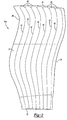
- Figure 5 is an enlarged view of two ribs 42 and of three adjacent side wall segments 48 on each detail half 30a, 30b.
- the wall segments 48 are straight between the ribs 42, as shown in contrast with prior art continuous curvature outer surfaces A and B, shown in phantom (curvature and angles are exaggerated in Figure 5 for illustration).
- Adjacent wall segments 48 extend at non-parallel angles relative to one another in order to follow the curves of the airfoil shape.
- opposite wall segments 48 i.e. on opposite detail halves 30a, b and connected between the same pair of joined ribs 42 also may not be parallel to one another as the thickness of the hollow fan blade 30 changes across its width.
- the sizing will depend upon the required load transitioning and carrying capabilities.
- the ratio of the width w of the cavity at the rib wall fillet run out to the thickness t of the side wall segment 48 should be less than ten, but can be larger if the rib can be aligned more parallel to the load.
- the straight wall segments 48 provide better resistance to buckling under compressive loads than the previously-used curved wall segments. Therefore, the thickness of the wall segments 48 can be reduced while maintaining durability. Reducing the thickness of the wall segments 48 can have a significant effect on the total weight of the engine 10 (Figure 1), by reducing the weight of not just the hollow fan blades 30, but also the required strength of the hub and the fan case 27 which must contain the fan blades 30.
Abstract
Description
- The present invention relates generally to gas turbine engines and more particularly to an improved hollow fan blade for a gas turbine engine.
- A gas turbine engine, such as a turbofan engine for an aircraft, includes a fan section, a compression section, a combustion section and a turbine section. An axis of the engine is centrally disposed within the engine and extends longitudinally through the sections. The primary flow path for working medium gases extends axially through the sections of the engine. A secondary flow path for working medium gases extends parallel to and radially outward of the primary flow path.
- The fan section includes a rotor assembly and a stator assembly. The rotor assembly of the fan includes a rotor disc and plurality of radially extending fan blades: The fan blades extend through the flow path and interact with the working medium gases and transfer energy between the fan blades and working medium gases. The stator assembly includes a fan case, which circumscribes the rotor assembly in close proximity to the tips of the fan blades.
- During operation, the fan draws the working medium gases, more particularly air, into the engine. The fan raises the pressure of the air drawn along the secondary flow path, thus producing useful thrust. The air drawn along the primary flow path into the compressor section is compressed. The compressed air is channeled to the combustion section where fuel is added to the compressed air and the air/fuel mixture is burned. The products of combustion are discharged to the turbine section. The turbine section extracts work from these products to power the fan and compressed air. Any energy from the products of combustion not needed to drive the fan and compressor contributes to useful thrust.
- In order to reduce weight, the fan blades in some gas turbine engines are hollow. Each fan blade is made by combining two separate detail halves. Each half includes a plurality of cavities and ribs machined out to reduce the weight while forming a structurally sound internal configuration. One half forms the pressure side wall and the other half forms the suction side wall. When the detail halves are joined, the pressure side wall and the suction side wall are separated and supported by the ribs to form the hollow fan blade. The hollow fan blade is then subjected to forming operations at extremely high temperatures at which time it is given an airfoil shape and geometry. The side walls are contoured and curved to form the airfoil.
- Fan blades must be capable of withstanding the impact of birds, ice or other foreign objects. These apply extreme initial loads at the leading edge, tending to cause bending of the airfoil at the leading edge, which applies a large compressive load to the suction side cavity walls. For this load, spanwise ribs and cavities offer the least resistance to buckling, and it's for this reason that advanced blade configurations feature outer span ribs that run chordwise. There are also secondary loads milliseconds after the impact as a shock wave radiates out from the impact site. These secondary loads flex the metal as they are passed onward. Subsequently, the blade tip will flex back and forth until the energy from the event can be absorbed. These motions alternate compressive and tensile loads to both pressure and suction cavity walls. Blade tips are also subject to circumferential loading when blades rub the case during heavy crosswinds or maneuver loading, or in a severe case, during a blade out event. Tip rubs apply similar compressive loads to the suction side cavity walls.
- Compressive loads on the walls between ribs can cause the walls to buckle, depending on the wall thickness and span and other geometry. These considerations increase the minimum wall thickness that must be used. This increases the blade weight, and with hub and containment considerations, the total engine weight.
- The present invention provides a hollow fan blade with improved resistance to buckling without adding wall thickness. The hollow fan blade includes a pressure side wall and a suction side wall separated and supported by ribs. In the preferred embodiment of the present invention, each wall segment between each adjacent pair of ribs is straight, not curved. At least some of the adjacent walls segments extend at non-parallel angles relative to one another to form the airfoil shape to the hollow fan blade.
- The resulting fan blade side walls have faceted surfaces, rather than a continuous smooth, curved surface. The straight wall segments between adjacent ribs can withstand higher compressive forces without buckling. As a result, the wall thickness can be reduced.
- Other advantages of the present invention can be understood by reference to the following detailed description when considered in connection with the accompanying drawings wherein:
- Figure 1 is a sectional view of an axial flow, turbo fan gas turbine engine with the hollow fan blades of the present invention.
- Figure 2 is a plan view of one detail half of one of the hollow fan blades of Figure 1.
- Figure 3 is a sectional view through three of the cavities of the detail half of Figure 2 and through a cutter for forming the cavities.
- Figure 4 is a sectional view through an assembled, formed fan blade corresponding to the fan blade detail half of Figure 2 and its complementary detail half.
- A
gas turbine engine 10, such as a turbofan gas turbine engine, circumferentially disposed about an engine centerline, oraxial centerline axis 12 is shown. Theengine 10 includes afan 14, acompressor 16, acombustion section 18 and aturbine 20. As is well known in the art, air compressed in thecompressor 16 is mixed with fuel, which is burned in thecombustion section 18 and expanded inturbine 20. The air compressed in the compressor and the fuel mixture expanded in theturbine 20 can both be referred to as a hotgas stream flow 28. Theturbine 20 includesrotors 22 that rotate in response to the expansion, driving thecompressor 16 andfan 14. Theturbine 20 comprises alternating rows of rotary airfoils orblades 24 and static airfoils orvanes 26. - The
fan 14 is surrounded by afan case 27 and includes a rotor assembly. The rotor assembly includes arotor disk 29 and a plurality offan blades 30. Eachfan blade 30 extends radially outwardly from therotor disk 29 across the working medium flow paths into proximity with thefan case 27. Thefan blades 30 are hollow fan blades and include a first hollow fan blade detail half 30a and a second hollow fanblade detail half 30b, one forming a pressure side wall and the other forming a suction side wall. - A first embodiment of one fan blade detail half 30a is shown in Figure 2. The other fan
blade detail half 30b would be complementary. The fanblade detail half 30a comprises asubstrate 31, preferably Titanium, having aroot edge 32 opposite atip 34 and a leadingedge 36 opposite atrailing edge 38. - In order to reduce weight while still maintaining the necessary stiffness and strength, a plurality of elongated
continuous cavities 40 are machined into the interior surface of thesubstrate 31. Thecavities 40 are spaced from one another to form a plurality of continuous, non-intersectingribs 42. Alternatively (or additionally), theribs 42 are superplastically formed. Thecavities 40 are all formed in thesubstrate 31 between theroot edge 32 and thetip 34, and between theleading edge 36 and trailingedge 38. - The
ribs 42 are oriented and biased in order to provide stiffness where needed, both during forming and during use in theturbine engine 10 of Figure 1. Further, theribs 42 curve and change direction to eliminate any long,straight cavities 40, which would have low inertia. Preferably, thecavities 40 do not continue in any direction for lengths greater than half the blade chord. Many different arrangements of thecavities 40 andribs 42 can be used with the present invention, depending upon the particular application. Several such arrangements are disclosed in co-pending, co-owned applicationsUS 2005-0163618A1 ,2005-0163620A1 ,2005-0160599A1 ,2005-0163619A1 ,2005-0163617A1 and HOLLOW FAN BLADE FOR GAS TURBINE ENGINE, filed August 15, 2005, SerialNo. 11/203,694 - Figure 3 is a sectional view of the
detail half 30a being machined by acutter 54. The floor of eachcavity 40 forms aside wall segment 48 between opposite wall interior surfaces 50, some of which define theribs 42. Eachcavity 40 further includes aradius 52 transition between the wallinterior surface 50 and theside wall segment 48. As shown, theside wall segment 48 and both wall interior surfaces 50 are preferably cut simultaneously in a single pass by thecutter 54. Because thecavities 40 are continuous and theribs 42 do not intersect, eachcavity 40 can be formed in a single pass with a single cutter. Alternatively, thecavities 40 may each be formed in a single rough cut and a series of finish cuts, but this is still a significant reduction in the number of cuts and cutters required. Additionally, because the floor has very little curvature prior to forming, thecutter 54 can be operated by a 3-axis machine 55 (shown schematically in Fig 3), Alternatively, to further reduce machining time it is possible to use a flat external airfoil surface with a curved bond face surface, which permits the cavities to be machined by a 3-axis machine with flat ended milling cutter. In addition, because there are no transversely-extending ribs intersecting theribs 42 the number of cutters of different diameters required is greatly reduced. A detail half could conceivably be done with a single form cutter, including both rough and finish passes. The other fanblade detail half 30b would be made in a similar manner. - Figure 4 is a sectional view of a portion of the
fan blade 30. Theribs 42 of fanblade detail half 30a are aligned and joined with theribs 42 of the fanblade detail half 30b. After thehalves 30a,b are bonded, thefan blade 30 is given an airfoil shape in a forming operation. During the forming operation, the two detail halves are twisted and cambered to the desired shape under high heat. As shown, theside wall segments 48 are straight, even after the forming operation. Theside wall segments 48 between each adjacent pair ofribs 42 are maintained straight (or straightened) during the forming operation. In order to form thefan blade 30 into an airfoil, adjacentside wall segments 48 are formed at a non-parallel angle relative to one another. This gives the outer surfaces of thedetail halves 30a,b a faceted appearance. - Figure 5 is an enlarged view of two
ribs 42 and of three adjacentside wall segments 48 on eachdetail half wall segments 48 are straight between theribs 42, as shown in contrast with prior art continuous curvature outer surfaces A and B, shown in phantom (curvature and angles are exaggerated in Figure 5 for illustration).Adjacent wall segments 48 extend at non-parallel angles relative to one another in order to follow the curves of the airfoil shape. Also, as can be noted from Figures 4 and 5, opposite wall segments 48 (i.e. onopposite detail halves 30a, b and connected between the same pair of joined ribs 42) also may not be parallel to one another as the thickness of thehollow fan blade 30 changes across its width. The sizing will depend upon the required load transitioning and carrying capabilities. Preferably, the ratio of the width w of the cavity at the rib wall fillet run out to the thickness t of theside wall segment 48 should be less than ten, but can be larger if the rib can be aligned more parallel to the load. - The
straight wall segments 48 provide better resistance to buckling under compressive loads than the previously-used curved wall segments. Therefore, the thickness of thewall segments 48 can be reduced while maintaining durability. Reducing the thickness of thewall segments 48 can have a significant effect on the total weight of the engine 10 (Figure 1), by reducing the weight of not just thehollow fan blades 30, but also the required strength of the hub and thefan case 27 which must contain thefan blades 30. - In accordance with the provisions of the patent statutes and jurisprudence, exemplary configurations described above are considered to represent a preferred embodiment of the invention. However, it should be noted that the invention can be practiced otherwise than as specifically illustrated and described without departing from its scope as defined by the following claims. Alphanumeric identifiers for steps in the method claims are for ease of reference by dependent claims, and do not indicate a required sequence, unless otherwise indicated.
Claims (16)
- A hollow fan blade (30) comprising:a pressure side wall (30a) having an exterior surface;a suction side wall (30b) having an exterior surface; anda plurality of ribs (42) extending between the pressure side wall (30a) and the suction side wall (30b), at least one of the pressure side wall (30a) and the suction side wall (30b) defining a straight wall segment (48) between at least one adjacent pair of the plurality of ribs (42).
- The hollow fan blade of claim 1 wherein straight wall segments (48) are provided between a plurality of adjacent pairs of the plurality of ribs (42).
- The hollow fan blade of claim 2, wherein straight wall segments (48) are provided between each adjacent pair of the plurality of ribs (42).
- The hollow fan blade of claim 2 or 3 wherein adjacent wall segments are not parallel to one another.
- A hollow fan blade (30) comprising:a pressure side wall (30a) having an exterior surface;a suction side wall (30b) having an exterior surface; anda plurality of ribs (42) extending between the pressure side wall (30a) and the suction side wall (30b), at least one of the pressure side wall (30a) and the suction side wall (30b) having a plurality of facets (48) between at least some adjacent pairs of the plurality of ribs (42).
- The hollow fan blade of claim 5 wherein an outer surface of the at least one of the pressure side wall (30a) and the suction side wall (30b) includes a facet surface (48) between each adjacent pair of the plurality of ribs (42).
- The hollow fan blade of claim 5 or 6 wherein the plurality of facets includes a plurality of straight wall segments (48).
- The hollow fan blade of any of claims 5 to 7 wherein adjacent facets (48) are not parallel to one another.
- The hollow fan blade of any preceding claim wherein the plurality of ribs (42) are at least partially defined by a plurality of substantially parallel, elongated, continuous cavities (40) formed in at least one of the pressure side wall (30a) and the suction side wall (30b).
- The hollow fan blade of any preceding claim wherein the plurality of ribs (42) are generally parallel to one another.
- The hollow fan blade of claim 10 wherein the plurality of ribs (42) curve in a first direction and then curve in an opposite second direction.
- A gas turbine engine including a plurality of the hollow fan blades of any preceding claim.
- A method for making a hollow fan blade detail half (30a, 30b) including the steps of:a) forming a set of substantially parallel continuous first rib portions (42) on a substrate in a first region, wherein the first rib portions (42) do not intersect one another or any other rib portions (42);b) forming a set of substantially parallel continuous first cavities (40) adjacent each of the first rib portions (42); andc) forming a straight wall segment (48) at a bottom of each of the first cavities (40).
- The method of claim 13 wherein said step c) further includes the step of curving the plurality of first rib portions (42) in a first direction and then curving the plurality of first rib portions (42) in an opposite second direction.
- The method of claim 14 wherein said step c) further includes the step of forming adjacent wall segments (48) at a non-parallel angle relative to one another.
- The method of claim 15 further including the step of forming a faceted outer surface on the detail half, the outer surface opposite the plurality of first rib portions (42).
Applications Claiming Priority (1)
| Application Number | Priority Date | Filing Date | Title |
|---|---|---|---|
| US11/295,335 US7993105B2 (en) | 2005-12-06 | 2005-12-06 | Hollow fan blade for gas turbine engine |
Publications (3)
| Publication Number | Publication Date |
|---|---|
| EP1795704A2 true EP1795704A2 (en) | 2007-06-13 |
| EP1795704A3 EP1795704A3 (en) | 2010-06-30 |
| EP1795704B1 EP1795704B1 (en) | 2012-01-18 |
Family
ID=37768758
Family Applications (1)
| Application Number | Title | Priority Date | Filing Date |
|---|---|---|---|
| EP06256211A Active EP1795704B1 (en) | 2005-12-06 | 2006-12-06 | Hollow fan blade for gas turbine engine, corresponding gas turbine engine and method for making a hollow fan blade detail half |
Country Status (3)
| Country | Link |
|---|---|
| US (1) | US7993105B2 (en) |
| EP (1) | EP1795704B1 (en) |
| JP (1) | JP2007154874A (en) |
Cited By (1)
| Publication number | Priority date | Publication date | Assignee | Title |
|---|---|---|---|---|
| FR3010747A1 (en) * | 2013-09-16 | 2015-03-20 | Valeo Systemes Thermiques | AUTOMOBILE FAN WITH OPTIMIZED BLADES FOR ACOUSTICS AND AERODYNAMICS |
Families Citing this family (25)
| Publication number | Priority date | Publication date | Assignee | Title |
|---|---|---|---|---|
| US8257035B2 (en) * | 2007-12-05 | 2012-09-04 | Siemens Energy, Inc. | Turbine vane for a gas turbine engine |
| US9752441B2 (en) | 2012-01-31 | 2017-09-05 | United Technologies Corporation | Gas turbine rotary blade with tip insert |
| US9810077B2 (en) | 2012-01-31 | 2017-11-07 | United Technologies Corporation | Fan blade attachment of gas turbine engine |
| US9121287B2 (en) | 2012-09-12 | 2015-09-01 | United Technologies Corporation | Hollow fan blade with honeycomb filler |
| US9453418B2 (en) | 2012-12-17 | 2016-09-27 | United Technologies Corporation | Hollow airfoil with composite cover and foam filler |
| US9359906B2 (en) | 2012-12-18 | 2016-06-07 | United Technologies Corporation | Rotor blade root spacer with a fracture feature |
| US9422819B2 (en) | 2012-12-18 | 2016-08-23 | United Technologies Corporation | Rotor blade root spacer for arranging between a rotor disk and a root of a rotor blade |
| US10458333B2 (en) * | 2014-02-19 | 2019-10-29 | United Technologies Corporation | Reduced stress boss geometry for a gas turbine engine |
| US9914170B2 (en) | 2014-06-13 | 2018-03-13 | Hamilton Sundstrand Corporation | Method for making an integrally bladed rotor with hollow blades |
| US10156157B2 (en) * | 2015-02-13 | 2018-12-18 | United Technologies Corporation | S-shaped trip strips in internally cooled components |
| CN106555776B (en) * | 2015-09-25 | 2019-04-12 | 中国航发商用航空发动机有限责任公司 | Turbofan and its fan blade |
| US10450867B2 (en) * | 2016-02-12 | 2019-10-22 | General Electric Company | Riblets for a flowpath surface of a turbomachine |
| CN107965468A (en) * | 2017-07-10 | 2018-04-27 | 常州信息职业技术学院 | A kind of flabellum blade construction |
| US11015461B2 (en) | 2017-12-21 | 2021-05-25 | General Electric Company | Composite hollow blade and a method of forming the composite hollow blade |
| US10677068B2 (en) | 2018-01-18 | 2020-06-09 | Raytheon Technologies Corporation | Fan blade with filled pocket |
| US11014190B2 (en) | 2019-01-08 | 2021-05-25 | Raytheon Technologies Corporation | Hollow airfoil with catenary profiles |
| US10808542B2 (en) | 2019-01-11 | 2020-10-20 | Raytheon Technologies Corporation | Method of forming gas turbine engine components |
| US10995632B2 (en) | 2019-03-11 | 2021-05-04 | Raytheon Technologies Corporation | Damped airfoil for a gas turbine engine |
| US11033993B2 (en) | 2019-03-20 | 2021-06-15 | Raytheon Technologies Corporation | Method of forming gas turbine engine components |
| US11236619B2 (en) | 2019-05-07 | 2022-02-01 | Raytheon Technologies Corporation | Multi-cover gas turbine engine component |
| US11370016B2 (en) | 2019-05-23 | 2022-06-28 | Raytheon Technologies Corporation | Assembly and method of forming gas turbine engine components |
| US11174737B2 (en) | 2019-06-12 | 2021-11-16 | Raytheon Technologies Corporation | Airfoil with cover for gas turbine engine |
| US11248477B2 (en) | 2019-08-02 | 2022-02-15 | Raytheon Technologies Corporation | Hybridized airfoil for a gas turbine engine |
| US11148221B2 (en) | 2019-08-29 | 2021-10-19 | Raytheon Technologies Corporation | Method of forming gas turbine engine components |
| CN112032109A (en) * | 2020-09-15 | 2020-12-04 | 中国航发沈阳发动机研究所 | Blade |
Citations (1)
| Publication number | Priority date | Publication date | Assignee | Title |
|---|---|---|---|---|
| US5269058A (en) * | 1992-12-16 | 1993-12-14 | General Electric Company | Design and processing method for manufacturing hollow airfoils |
Family Cites Families (33)
| Publication number | Priority date | Publication date | Assignee | Title |
|---|---|---|---|---|
| GB619107A (en) | 1946-11-21 | 1949-03-03 | Brush Electrical Eng | Improvements in and relating to turbine blading |
| US2644665A (en) * | 1947-12-13 | 1953-07-07 | Chrysler Corp | Article with passages |
| US3017159A (en) * | 1956-11-23 | 1962-01-16 | Curtiss Wright Corp | Hollow blade construction |
| US3533712A (en) * | 1966-02-26 | 1970-10-13 | Gen Electric | Cooled vane structure for high temperature turbines |
| DE1751938B1 (en) * | 1968-08-21 | 1970-12-03 | Messerschmitt Boelkow Blohm | Process for the production of the cooling ducts for rocket combustion chambers with convergent-divergent thrust nozzle |
| US3628226A (en) * | 1970-03-16 | 1971-12-21 | Aerojet General Co | Method of making hollow compressor blades |
| FR2516165B1 (en) * | 1981-11-10 | 1986-07-04 | Snecma | GAS TURBINE BLADE WITH FLUID CIRCULATION COOLING CHAMBER AND METHOD FOR PRODUCING THE SAME |
| JPS58148201A (en) | 1982-02-26 | 1983-09-03 | Toshiba Corp | Cooled part of gas turbine |
| US4501053A (en) * | 1982-06-14 | 1985-02-26 | United Technologies Corporation | Method of making rotor blade for a rotary machine |
| US4574451A (en) * | 1982-12-22 | 1986-03-11 | General Electric Company | Method for producing an article with a fluid passage |
| US4514144A (en) * | 1983-06-20 | 1985-04-30 | General Electric Company | Angled turbulence promoter |
| DE3339751A1 (en) * | 1983-11-03 | 1985-05-15 | BBC Aktiengesellschaft Brown, Boveri & Cie., Baden, Aargau | JOINT PROCESS |
| US5063662A (en) * | 1990-03-22 | 1991-11-12 | United Technologies Corporation | Method of forming a hollow blade |
| US5099573A (en) | 1990-06-27 | 1992-03-31 | Compressor Components Textron Inc. | Method of making hollow articles |
| US5253824A (en) * | 1991-04-16 | 1993-10-19 | General Electric Company | Hollow core airfoil |
| US5246340A (en) * | 1991-11-19 | 1993-09-21 | Allied-Signal Inc. | Internally cooled airfoil |
| US5516593A (en) * | 1994-04-29 | 1996-05-14 | United Technologies Corporation | Article with material absorption cavities to reduce buckling during diffusion bonding |
| US5536143A (en) * | 1995-03-31 | 1996-07-16 | General Electric Co. | Closed circuit steam cooled bucket |
| US5820338A (en) * | 1997-04-24 | 1998-10-13 | United Technologies Corporation | Fan blade interplatform seal |
| US5836744A (en) * | 1997-04-24 | 1998-11-17 | United Technologies Corporation | Frangible fan blade |
| US6048174A (en) | 1997-09-10 | 2000-04-11 | United Technologies Corporation | Impact resistant hollow airfoils |
| DE19743694C2 (en) * | 1997-10-02 | 2001-11-15 | Aloys Wobben | Rotor blade and wind turbine with one rotor blade |
| WO1999021680A2 (en) * | 1997-10-27 | 1999-05-06 | Siemens Westinghouse Power Corporation | Turbine blades made from multiple single crystal cast superalloy segments |
| US6637186B1 (en) * | 1997-11-11 | 2003-10-28 | United Technologies Corporation | Fan case liner |
| US5997251A (en) * | 1997-11-17 | 1999-12-07 | General Electric Company | Ribbed turbine blade tip |
| US6099252A (en) * | 1998-11-16 | 2000-08-08 | General Electric Company | Axial serpentine cooled airfoil |
| US6340047B1 (en) * | 1999-03-22 | 2002-01-22 | General Electric Company | Core tied cast airfoil |
| US6607355B2 (en) * | 2001-10-09 | 2003-08-19 | United Technologies Corporation | Turbine airfoil with enhanced heat transfer |
| US6994524B2 (en) * | 2004-01-26 | 2006-02-07 | United Technologies Corporation | Hollow fan blade for gas turbine engine |
| US7334333B2 (en) * | 2004-01-26 | 2008-02-26 | United Technologies Corporation | Method for making a hollow fan blade with machined internal cavities |
| US7052238B2 (en) * | 2004-01-26 | 2006-05-30 | United Technologies Corporation | Hollow fan blade for gas turbine engine |
| US7070391B2 (en) * | 2004-01-26 | 2006-07-04 | United Technologies Corporation | Hollow fan blade for gas turbine engine |
| US6994525B2 (en) * | 2004-01-26 | 2006-02-07 | United Technologies Corporation | Hollow fan blade for gas turbine engine |
-
2005
- 2005-12-06 US US11/295,335 patent/US7993105B2/en active Active
-
2006
- 2006-11-09 JP JP2006303534A patent/JP2007154874A/en active Pending
- 2006-12-06 EP EP06256211A patent/EP1795704B1/en active Active
Patent Citations (1)
| Publication number | Priority date | Publication date | Assignee | Title |
|---|---|---|---|---|
| US5269058A (en) * | 1992-12-16 | 1993-12-14 | General Electric Company | Design and processing method for manufacturing hollow airfoils |
Cited By (1)
| Publication number | Priority date | Publication date | Assignee | Title |
|---|---|---|---|---|
| FR3010747A1 (en) * | 2013-09-16 | 2015-03-20 | Valeo Systemes Thermiques | AUTOMOBILE FAN WITH OPTIMIZED BLADES FOR ACOUSTICS AND AERODYNAMICS |
Also Published As
| Publication number | Publication date |
|---|---|
| EP1795704A3 (en) | 2010-06-30 |
| EP1795704B1 (en) | 2012-01-18 |
| US20070128042A1 (en) | 2007-06-07 |
| US7993105B2 (en) | 2011-08-09 |
| JP2007154874A (en) | 2007-06-21 |
Similar Documents
| Publication | Publication Date | Title |
|---|---|---|
| EP1795704B1 (en) | Hollow fan blade for gas turbine engine, corresponding gas turbine engine and method for making a hollow fan blade detail half | |
| EP1754857B1 (en) | Hollow fan blade detail half, hollow fan blade for a gas turbine engine, gas turbine engine and corresponding manufacturing method | |
| EP1557528B1 (en) | Hollow fan blade detail half, hollow fan blade for a gas turbine engine and corresponding manufacturing method | |
| EP1557530B1 (en) | Method of making a hollow fan blade for a gas turbine engine | |
| EP1557532B1 (en) | Hollow fan blade detail half, hollow fan blade for a gas turbine engine and corresponding manufacturing method | |
| EP1557529B1 (en) | Hollow fan blade for gas turbine engine and corresponding manufacturing method | |
| EP1557531B1 (en) | Hollow fan blade half, hollow fan blade for a gas turbine engine and corresponding manufacturing method | |
| EP1890008B1 (en) | Rotor blade | |
| EP1939399B1 (en) | Axial flow turbine assembly | |
| EP2925970B1 (en) | Trailing edge and tip cooling | |
| EP1939405B1 (en) | Axial flow turbine assembly | |
| US20090097979A1 (en) | Rotor blade | |
| EP3441566A1 (en) | Airfoil with maximum thickness distribution for robustness |
Legal Events
| Date | Code | Title | Description |
|---|---|---|---|
| PUAI | Public reference made under article 153(3) epc to a published international application that has entered the european phase |
Free format text: ORIGINAL CODE: 0009012 |
|
| AK | Designated contracting states |
Kind code of ref document: A2 Designated state(s): AT BE BG CH CY CZ DE DK EE ES FI FR GB GR HU IE IS IT LI LT LU LV MC NL PL PT RO SE SI SK TR |
|
| AX | Request for extension of the european patent |
Extension state: AL BA HR MK YU |
|
| PUAL | Search report despatched |
Free format text: ORIGINAL CODE: 0009013 |
|
| AK | Designated contracting states |
Kind code of ref document: A3 Designated state(s): AT BE BG CH CY CZ DE DK EE ES FI FR GB GR HU IE IS IT LI LT LU LV MC NL PL PT RO SE SI SK TR |
|
| AX | Request for extension of the european patent |
Extension state: AL BA HR MK RS |
|
| 17P | Request for examination filed |
Effective date: 20101223 |
|
| AKX | Designation fees paid |
Designated state(s): DE GB |
|
| RIC1 | Information provided on ipc code assigned before grant |
Ipc: F04D 29/38 20060101ALI20110608BHEP Ipc: F04D 29/32 20060101ALI20110608BHEP Ipc: B23P 15/04 20060101ALI20110608BHEP Ipc: F01D 5/18 20060101ALI20110608BHEP Ipc: F01D 5/14 20060101AFI20110608BHEP |
|
| RTI1 | Title (correction) |
Free format text: HOLLOW FAN BLADE FOR GAS TURBINE ENGINE, CORRESPONDING GAS TURBINE ENGINE AND METHOD FOR MAKING A HOLLOW FAN BLADE DETAIL HALF |
|
| GRAP | Despatch of communication of intention to grant a patent |
Free format text: ORIGINAL CODE: EPIDOSNIGR1 |
|
| GRAS | Grant fee paid |
Free format text: ORIGINAL CODE: EPIDOSNIGR3 |
|
| GRAA | (expected) grant |
Free format text: ORIGINAL CODE: 0009210 |
|
| AK | Designated contracting states |
Kind code of ref document: B1 Designated state(s): DE GB |
|
| REG | Reference to a national code |
Ref country code: GB Ref legal event code: FG4D |
|
| REG | Reference to a national code |
Ref country code: DE Ref legal event code: R081 Ref document number: 602006027142 Country of ref document: DE Owner name: UNITED TECHNOLOGIES CORP. (N.D.GES.D. STAATES , US Free format text: FORMER OWNER: UNITED TECHNOLOGIES CORPORATION, HARTFORD, CONN., US |
|
| REG | Reference to a national code |
Ref country code: DE Ref legal event code: R096 Ref document number: 602006027142 Country of ref document: DE Effective date: 20120315 |
|
| PLBE | No opposition filed within time limit |
Free format text: ORIGINAL CODE: 0009261 |
|
| STAA | Information on the status of an ep patent application or granted ep patent |
Free format text: STATUS: NO OPPOSITION FILED WITHIN TIME LIMIT |
|
| 26N | No opposition filed |
Effective date: 20121019 |
|
| REG | Reference to a national code |
Ref country code: DE Ref legal event code: R097 Ref document number: 602006027142 Country of ref document: DE Effective date: 20121019 |
|
| REG | Reference to a national code |
Ref country code: DE Ref legal event code: R082 Ref document number: 602006027142 Country of ref document: DE Representative=s name: SCHMITT-NILSON SCHRAUD WAIBEL WOHLFROM PATENTA, DE |
|
| REG | Reference to a national code |
Ref country code: DE Ref legal event code: R082 Ref document number: 602006027142 Country of ref document: DE Representative=s name: SCHMITT-NILSON SCHRAUD WAIBEL WOHLFROM PATENTA, DE Ref country code: DE Ref legal event code: R081 Ref document number: 602006027142 Country of ref document: DE Owner name: UNITED TECHNOLOGIES CORP. (N.D.GES.D. STAATES , US Free format text: FORMER OWNER: UNITED TECHNOLOGIES CORPORATION, HARTFORD, CONN., US |
|
| PGFP | Annual fee paid to national office [announced via postgrant information from national office to epo] |
Ref country code: DE Payment date: 20191119 Year of fee payment: 14 |
|
| REG | Reference to a national code |
Ref country code: DE Ref legal event code: R119 Ref document number: 602006027142 Country of ref document: DE |
|
| PG25 | Lapsed in a contracting state [announced via postgrant information from national office to epo] |
Ref country code: DE Free format text: LAPSE BECAUSE OF NON-PAYMENT OF DUE FEES Effective date: 20210701 |
|
| PGFP | Annual fee paid to national office [announced via postgrant information from national office to epo] |
Ref country code: GB Payment date: 20231121 Year of fee payment: 18 |